DT-R17L4DU - Suivi JVC - Free user manual and instructions
Find the device manual for free DT-R17L4DU JVC in PDF.

User questions about DT-R17L4DU JVC
0 question about this device. Answer the ones you know or ask your own.
Ask a new question about this device
Download the instructions for your Suivi in PDF format for free! Find your manual DT-R17L4DU - JVC and take your electronic device back in hand. On this page are published all the documents necessary for the use of your device. DT-R17L4DU by JVC.
USER MANUAL DT-R17L4DU JVC
text_image
CAUTION RISK OF ELECTRICAL SHOCK DO NOT OPEN CAUTION: To reduce the risk of electric shock. Do not remove cover (or back). No user serviceable parts inside. Refer servicing to qualified service personnel. The lightning flash with arrowhead symbol, within an equilateral triangle is intended to alert the user to the presence of uninsulated "dangerous voltage" within the product's enclosure that may be of sufficient magnitude to constitute a risk of electric shock to persons. The exclamation point within an equilateral triangle is intended to alert the user to the presence of important operating and maintenance (servicing) instructions in the literature accompanying the appliance.DT-R24L4D
DT-R17L4D
MULTI FORMAT LCD MONITOR INSTRUCTIONS
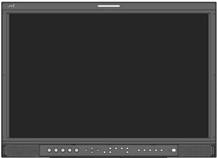
natural_image
Front view of a JVC computer monitor with control buttons and a blank screen (no text or symbols visible)The illustration of the monitor is of DT-R24L4D.
Safety Precautions 3
IMPORTANT SAFEGUARDS .... 3
Caution for use of the product for many hours.... 5
Caution for use of the product in the high temperature 5
Maintenance 5
Installation 6
Connections 8
Rear panel 8
Daily Operations 10
Front panel....10
Menu Configuration 12
The operation procedure.... 12
Menu Transition Diagram.... 12
MAIN MENU 13
SET-UP MENU 15
External Control 18
About the external control 18
Using the MAKE/TRIGGER system 18
Using the serial communication 20
Troubleshooting 22
Self-check program 23
Specifications 24
General 24
LCD panel 24
Input/output terminals 24
Dimensions 25
Available signals 26
WARNING: TO REDUCE RISK OF FIRE OR ELECTRIC SHOCK, DO NOT EXPOSE THIS APPARATUS TO RAIN OR MOISTURE. NO OBJECTS FILLED WITH LIQUIDS, SUCH AS VASES, SHALL BE PLACED ON THE APPARATUS.
IMPORTANT SAFEGUARDS
Electrical energy can perform many useful functions. This unit has been engineered and manufactured to assure your personal safety. But IMPROPER USE CAN RESULT IN POTENTIAL ELECTRIC
SHOCK OR FIRE. In order not to defeat the safeguards incorporated into this product, observe the following basic rules for its installation, use, and service. Please read these "IMPORTANT SAFEGUARDS" carefully before use.
- All the safety and operating instructions should be read before the product is operated.
- The safety and operating instructions should be retained for future reference.
- All warnings on the product and in the operating instructions should be adhered to.
- All operating instructions should be followed.
POWER CONNECTION
The power supply voltage rating of this product is AC 120 V (For U.S.A. and Canada) and AC 220 – 240 V (For European countries, Asian countries, and United Kingdom).
The power cord attached conforms to the following power supply voltage and countries. Use only the power cord designated to ensure safety and EMC regulations of each country.
- Not all types of power cords are supplied to this product.
For U.S.A. and
Canada: AC 120 V
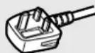
For European and Asian countries: AC 220 – 240 V
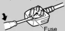
For United Kingdom: AC 220 - 240 V

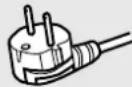
This plug will fit only into a grounded power outlet. If you are unable to insert the plug into the outlet, contact your electrician to install the proper outlet. Do not defeat the safety purpose of the grounded plug.
- This product should be operated only with the type of power source indicated on the label. If you are not sure of the type of power supply of your home, consult your product dealer or local electric power company.
Warning:
- Do not use the same power cord for AC 120 V as for AC 220 – 240 V. Doing so may cause malfunction, electric shock or fire.
Note for United Kingdom power cord only
The plug of United Kingdom power cord has a built-in fuse. When replacing the fuse, be sure to use only a correctly rated approved type, re-fit the fuse cover. (Consult your dealer or qualified personnel.)
How to replace the fuse
Open the fuse compartment with the blade screwdriver, and replace the fuse.
Warning: This is a class A product. In a domestic environment this product may cause radio interference in which case the user may be required to take adequate measures.
- Before connecting other products such as VCR's and personal computers, you should turn off the power of this product for protection against electric shock.
- Do not use attachments not recommended by the manufacturer as they may be hazardous.
- When replacement parts are required, be sure the service technician has used replacement parts specified by the manufacturer or equivalents. Unauthorized substitutions may result in fire, electric shock, or other hazards.
- Upon completion of any service or repairs to this product, ask the service technician to perform safety checks to determine that the product is in proper operating condition.
Under the following conditions,
- Turn off the power.
- Unplug this product from the wall outlet.
-
Refer service to qualifi ed service personnel.
a) When the product emits smoke or unusual smell.
b) When the product exhibits a distinct change in performance —for example, no picture or no sound.
c) If liquid has been spilled, or objects have fallen on the product.
d) If the product has been exposed to rain or water.
e) If the product has been dropped or damaged in any way.
f) When the power supply cord or plug is damaged. -
Do not install this product in the following places: – in a damp or dusty room
- where the product is exposed to soot or steam, such as near the cooking counter or a humidifier
- near heat sources
- where condensation easily occurs, such as near the window
- in a location exposed to direct sunlight or strong light
- Do not place this product on an unstable cart, stand, or table. The product may fall, causing serious injury to a child or adult, and serious damage to the product.
The product should be mounted according to the manufacturer's instructions, and should use a mount recommended by the manufacturer.
- Do not use this product near water.
- Be sure to install the product in the place where proper temperature and humidity are kept (“Operating conditions” on page 24).
This product becomes hot during its use. Take enough care when handling the product.
Do not attempt to service this product yourself, as opening or removing covers may expose you to dangerous voltages and other hazards. Refer all service to qualified service personnel.
Do not use the product for a long time if the sound is distorted.
Use only the power source specified on the unit.
• AC power: 120 V/220 – 240 V, 50 Hz/60 Hz
- The AC power supply is controlled by turning on/off the POWER switch on the rear panel. If the product is installed in a place where you cannot easily turn on/off the POWER switch, control the AC power supply by plugging/unplugging the power cord into/from the AC outlet. In this case, install the product as close to the AC outlet as possible, and leave enough space for plugging/unplugging the power cord. If the product is installed in a place where you cannot easily plug/unplug the power cord, equip an easily accessible device to the wiring of the building for turning on/off the power.
- When the product is left unattended and unused for a long period of time, unplug it from the wall outlet and disconnect the cable system.
- Do not overload wall outlets, extension cords, or convenience receptacles on other equipment as this can result in a risk of fire or electric shock.
-
Use only the accessory cord designed for this product to prevent shock.
-
Slots and openings in the cabinet are provided for ventilation. These ensure reliable operation of the product and protect it from overheating. These openings must not be blocked or covered.
- Never push objects of any kind into this product through openings as they may touch dangerous voltage points or short-circuit the parts, which could result in a fi re or electric shock.
- Never spill liquid of any kind on the product.
- Never place anything on the product. (Placing liquids, naked flames, cloths, paper, etc. on the product may cause a fire.)
- Do not apply any strong shock to the LCD panel. (Do not hit any object against it or push it with a sharp-pointed tool.)
- Do not put heavy objects on the product.
- Do not step on or hang on the product.
To prevent an accidental fall
Fix the monitor to a wall by using strings.
Fixing the monitor
Attach the hook (not provided) to the VESA mounting holes on the rear panel (use the two holes on the upper side) using M4 x 10 mm screws (not provided). Bind the hooks on the rear panel of the monitor to a wall or a pillar using durable string.

text_image
VESA mounting holes Hook and screw (M4 x 10 mm) (not provided) Hook (not provided)The illustration of the monitor is of DT-R24L4D.
U.S.A. only
FCC NOTICE
CAUTION: Changes or modifications not approved by JVC could void the user's authority to operate the equipment.
NOTE: This equipment has been tested and found to comply with the limits for a Class A digital device, pursuant to Part 15 of the FCC Rules. These limits are designed to provide reasonable protection against harmful interference when the equipment is operated in a commercial environment. This equipment generates, uses, and can radiate radio frequency energy and, if not installed and used in accordance with the instruction manual, may cause harmful interference to radio communications. Operation of this equipment in a residential area is likely to cause harmful interference in which case the user will be required to correct the interference at his own expense.
IMPORTANT RECYCLING INFORMATION
This product has a fluorescent lamp that contains mercury. Disposal of these materials may be regulated in your community due to environmental considerations. For disposal or recycling information, please contact your local authorities or for USA, the Electronic Industries Alliance: http://www.eiae.org
WARNING: TO PREVENT FIRE OR SHOCK HAZARDS, DO NOT EXPOSE THIS APPARATUS TO RAIN OR MOISTURE.
WARNING: THIS APPARATUS MUST BE CONNECTED TO A MAINS SOCKET OUTLET WITH A PROTECTIVE EARTHING CONNECTION.
CAUTION: DANGER OF EXPLOSION IF BATTERY IS INCORRECTLY REPLACED. REPLACE ONLY WITH THE SAME OR EQUIVALENT TYPE.
IMPORTANT SAFETY INSTRUCTIONS
1) Read these instructions.
2) Keep these instructions.
3) Heed all warnings.
4) Follow all instructions.
5) Do not use this apparatus near water.
6) Clean only with dry cloth.
7) Do not block any ventilation openings. Install in accordance with the manufacturer's instructions.
8) Do not install near any heat sources such as radiators, heat registers, stoves, or other apparatus (including amplifiers) that produce heat.
9) Do not defeat the safety purpose of the polarized or grounding-type plug. A polarized plug has two blades with one wider than the other. A grounding type plug has two blades and a third grounding prong. The wide blade or the third prong are provided for your safety. If the provided plug does not fit into your outlet, consult an electrician for replacement of the obsolete outlet.
10) Protect the power cord from being walked on or pinched particularly at plugs, convenience receptacles, and the point where they exit from the apparatus.
11) Only use attachments/accessories specified by the manufacturer.
12) Use only with the cart, stand, tripod, bracket, or table specified by the manufacturer, or sold with the apparatus. When a cart is used, use caution when moving the cart/apparatus combination to avoid injury from tip-over.
13) Unplug this apparatus during lightning storms or when unused for long periods of time.
14) Refer all servicing to qualified service personnel. Servicing is required when the apparatus has been damaged in any way, such as power-supply cord or plug is damaged, liquid has been spilled or objects have fallen into the apparatus, the apparatus has been exposed to rain or moisture, does not operate normally, or has been dropped.
15) Apparatus shall not be exposed to dripping or splashing and no objects filled with liquids, such as vases, shall be placed on the apparatus.
16) Batteries shall not be exposed to excessive heat such as sunshine, fire or the like.
17) When discarding batteries, environmental problems must be considered and the local rules or laws governing the disposal of these batteries must be followed strictly.

European Union only
Dear Customer,
This apparatus is in conformance with the valid European directives and standards regarding electromagnetic compatibility and electrical safety.
European representative of Victor Company of Japan, Limited is: JVC Technical Services Europe GmbH
Postfach 10 05 04
61145 Friedberg
Germany
Information for Users on Disposal of Old Equipment

[European Union]
This symbol indicates that the electrical and electronic equipment should not be disposed as general household waste at its end-of-life. Instead, the product should be handed over to the applicable collection point for the recycling of electrical and electronic equipment for proper treatment, recovery and recycling in accordance with your national legislation.
Attention: This symbol is only valid in the European Union.
By disposing of this product correctly, you will help to conserve natural resources and will help prevent potential negative effects on the environment and human health which could otherwise be caused by inappropriate waste
handling of this product. For more information about collection point and recycling of this product, please contact your local municipal offi ce, your household waste disposal service or the shop where you purchased the product.
Penalties may be applicable for incorrect disposal of this waste, in accordance with national legislation.
(Business users)
If you wish to dispose of this product, please visit our web page http://www.jvc.eu/ to obtain information about the take-back of the product.
[Other Countries outside the European Union]
If you wish to dispose of this product, please do so in accordance with applicable national legislation or other rules in your country for the treatment of old electrical and electronic equipment.
EMC Supplement
This equipment is in conformity with the provisions and protection requirements of the corresponding European Directives. This equipment is designed for professional video appliances and can be used in the following environments:
- Controlled EMC environment (for example purpose built broadcasting or recording studio), and rural outdoors environment (far away from railways, transmitters, overhead power lines, etc.) In order to keep the best performance and ensure electromagnetic compatibility, we recommend to use cables not exceeding the following length:
Cable Length
| Power cord(attached cable (H05VV-F 3 x 0.75 mm ^2 )) | 2.0 m |
| Video signal cable (coaxial cable) 2.0 m | |
| Audio signal cable (shielded cable) 1.5 m | |
| DVI cable (shielded cable) with core filter 2.0 m | |
| RS-232C cable (shielded cable)(A straight cable with a D-sub 9-pin connector) | 2.0 m |
| RS-485 cable (twist pair cable)(A straight LAN cable) | 2.0 m |
| REMOTE cable (twist pair cable)(A straight LAN cable) | 2.0 m |
Inrush current of the apparatus DT-R17L4D : 14.80 ampere DT-R24L4D
CAUTION
In case where the strong electromagnetic waves or magnetism are near the audio cable or the signal cable, the sound or the picture will contain noise. In such cases, please keep the cable away from the sources of the disturbance.
■ Caution for use of the product for many hours
In the case that you use the monitor for many hours, we recommend that you set "NO SYNC ACTION" in "SYNC FUNCTION" to "P.SAVE" in MAIN MENU. This will reduce power consumption and relieve strain on the monitor.
■ Caution for use of the product in the high temperature
Do not use the product in places of high temperature; otherwise, parts of this product or the LCD panel may be damaged. This product is equipped with a temperature sensor to give warning if the temperature becomes too high. If the temperature exceeds the range of normal use, "TEMP. OVER" is displayed, and the power is turned off automatically if the temperature becomes any higher. In this case, move the product to a place of low temperature to let it cool down.
■ Maintenance
Unplug this product from the wall outlet before cleaning.
Screen
To avoid irreparable change in appearance of the screen such as uneven color, discoloration, scratches, be careful about the following:
- Do not paste or stick anything using any glues or adhesive tapes.
- Do not write anything on the screen.
- Do not strike the screen with a hard object.
- Avoid condensation on the screen.
- Do not wipe the screen with solvent such as alcohol, thinner, or benzine.
- Do not wipe the screen forcefully.
Wipe stains off the screen with a soft cloth. If the screen gets heavily stained, wipe it with a soft cloth soaked in water-diluted neutral detergent and wrung well, then wipe with a soft dry cloth.
Cabinet
To avoid the deterioration or damages of the cabinet such as its paint's peeling away, be careful about the following:
- Do not wipe the cabinet using solvent such as alcohol, thinner, or benzine.
- Do not expose the cabinet to any volatile substance such as insecticides.
- Do not allow any rubber or plastic in contact for a long time.
- Do not wipe the cabinet forcefully.
Wipe stains off the cabinet with a soft cloth. If the cabinet gets heavily stained, wipe it with a soft cloth soaked in water-diluted neutral detergent and wrung well, then wipe with a soft dry cloth.
Ventilation openings
Use a vacuum cleaner to get rid of the dust around the intakes (all the openings). If a vacuum cleaner is not available, use a cloth and wipe it off. Leaving the dust around the intakes may prevent proper temperature control and cause damage to the product.
CAUTION
- Do not rest your arm on the monitor or lean against the monitor.
- Do not touch the LCD panel when installing the monitor.
- Be sure to install the monitor securely to prevent the monitor from falling over, which may cause damage to the monitor or injury.
To install the monitor on a shelf or any other suitable surface using screws
You can install the monitor without protruding the stand bottom plate by moving the stand bottom plate to the rear position.
CAUTION
- Lay the monitor on a cloth with the LCD panel facing down to prevent the LCD panel from being damaged.
• After moving the stand bottom plate to the rear position, be sure to attach the stand with commercially available screws.
1 Loosen the stand screws on the stand support and remove the bottom plate.

text_image
Bottom plate Stand support2 Temporarily set the stand screws to screw holes "3" on the right and left sides of the stand support.
- Tighten the temporarily set stand screws so that they protrude from the screw holes by about 4 mm.
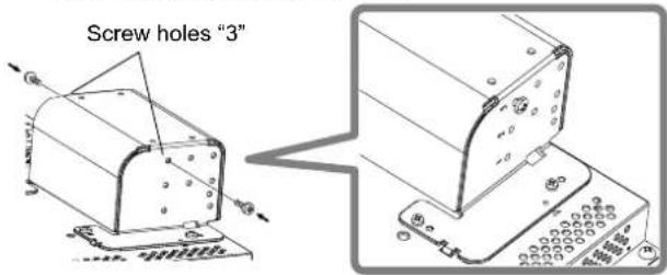
text_image
Screw holes "3"3 Hook right and left recesses "A" onto the temporarily set screws in the stand support.
Recesses "A"

text_image
Access A 0 0 0 0 0 0 0 0 0 0 0 0 0 0 0 0 0 0 0 0 0 0 0 0 0 0 0 0 0 0 0 0 0 0 0 0 0 0 0 0 0 0 0 0 0 0 0 0 0 0 1 2 3 4 5 6 7 8 9 10 11 12 13 14 15 16 17 18 19 20 21 22 23 24 25 26 27 28 29 30 31 32 33 34 35 36 37 38 39 40 41 42 43 44 45 46 47 48 49 504 Adjust the position so that the screw holes on the stand support align with right and left screw holes "C" and "E" on the bottom plate, tighten the two stand screws on one side (four screws on both sides), and finally retighten the temporarily set screws to lock the stand support and the bottom plate.
Screw hole "C" and "E"
natural_image
Technical line drawing of a mechanical assembly with two views (top and side), no visible text or symbols5 Use no less than two commercially available screws (no less than four screws on both sides) for the screw holes (10 - 8 ) on the stand bottom plate, to anchor the monitor. (Use screws having enough holding strength and resistance against external force of expected vibrations.)
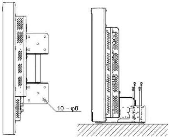
text_image
10 - φ8CAUTION
It is very dangerous not to anchor the stand with screws as this may cause not only breakage due to the monitor falling or dropping, but also injury or electrical shock.
To detach the stand
CAUTION
Lay the monitor on a cloth with the LCD panel facing down to prevent the LCD panel from being damaged.

text_image
Attachment screws Screw holes for stand attachment Stand body MonitorThe illustration of the monitor is of DT-R24L4D
To install the stand
When attaching the stand to the monitor, insert the guides of the stand into the guide holes on the monitor to place the stand in the correct position. Then fix the stand firmly with the attachment screws.

text_image
Guide holes Guides Monitor Screw holes for stand attachment Stand support Stand bodyThe illustration of the monitor is of DT-R24L4D.
To install the monitor on a wall
You can install the monitor on a wall by changing how the stand bottom plate is attached.
Installation Only for Authorized Service Personnel Consult authorized service personnel for the installation of this unit. Installation instructions must be followed precisely in order to prevent accidents. We are selling this product with the understanding that it will be assembled and installed by properly trained and qualified service personnel.
We are not liable for any damage caused by faulty assembly, faulty wall mounting, insecure wall mounting, misuse, alterations, or natural disasters.
- Please be aware that screw holes and anchor bolts will remain in the wall surface if the monitor is removed after having been mounted to the wall. Long-term use of the LCD display monitor may result in discoloration of the wall surface due to heat/air emitted by the display.

Danger
- Consult authorized service personnel for the installation and attachment of this unit to the wall. Do not attempt to mount the unit by yourself. This unit weighs 12 kg at maximum (26.5 lbs. at maximum), including LCD display monitor. Improper assembly or installation may cause the unit to fall when it is mounted, which may result in fatal accidents. To prevent this happening, check the strength of the materials in the mounting surface. Check the material strength again after mounting as well.

Warning
- Using a monitor other than this product may result in damage or bodily injury due to the LCD display monitor toppling over.
- Assemble all screws securely. Failure to do so may result in the LCD monitor and stand falling down, potentially causing damage or bodily injury.
- This unit does not come with anchor bolts for securing it to walls, etc. Be sure you have materials on hand as appropriate for the mounting location.
- The monitor should be mounted to a wall that can adequately hold the total weight of the monitor and stand over a long period of time and which can adequately withstand earthquakes, conceivable vibrations, and other external forces.
- Mounting On Wooden Walls The weight of the unit should be borne by the wall posts or studs, and these should be reinforced if insufficiently strong. Do not install the Wall Mounting Unit on walls made of plasterboard or thin plywood. Use the commercially sold screws best suited for the wall structure and material.
- Mounting On Concrete Walls Use commercially sold wall anchors capable of supporting the weight of the LCD monitor.
- Do not install the Wall Mounting Unit near the blower or air inlet of an air conditioner.
- Do not install the Wall Mounting Unit in a location subject to frequent vibration, impact or other external forces.
- Do not install the unit in a location where people may hang on it or lean against it.
- Do not block the ventilation holes.
- Do not install the monitor on a non-vertical wall.

Caution
- Consult authorized service personnel for electrical work. Using power cords damaged during installation (i.e., exposed or severed wiring) may result in fi re or electric shock.
- Conduct the work with adequate working space. Damage or bodily injury may result from working under unsuitable conditions.
- Avoid mounting this unit in areas where there is electrical wiring or water pipes, as fire or electric shock may result.
1 Lay the monitor on a cloth with the LCD panel facing down to prevent the LCD panel from being damaged. Loosen the stand screws on the stand support and remove the bottom plate.

text_image
Bottom plate Stand support2 Temporarily set the stand screws in screw holes "2" and "4" on the right and left sides of the stand support.
- Tighten the temporarily set stand screws so that they protrude from the screw holes by about 4 mm.
Stand screws "2" and "4"
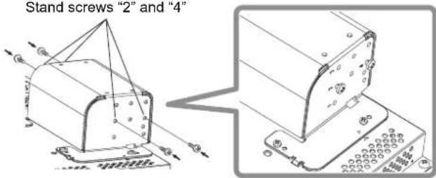
text_image
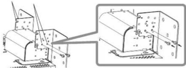
Stand screws "2" and "4"3 Tighten commercially available screws in the 6 holes shown in the figure below to install the monitor on the wall.
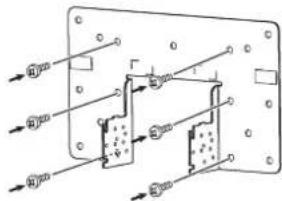
text_image
Technical diagram of a mechanical or electrical component with labeled dimensions and directional arrows indicating flow or movement.4 Hook the temporarily set screws on the stand support in right and left recesses "A" and "B" on the bottom plate, tighten the two stand screws in right and left screw holes "D" and finally retighten the temporarily set screws to lock the stand support and bottom plate.
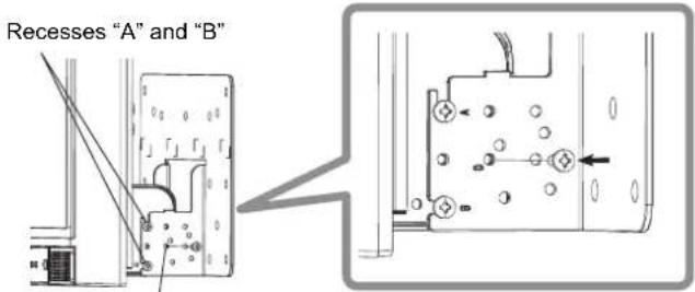
text_image
Recesses "A" and "B"Screw holes "D"
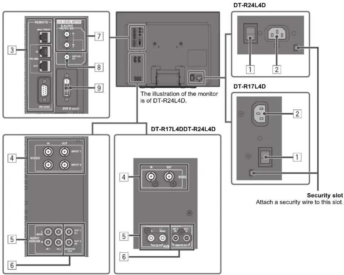
Rear panel
flowchart
graph TD
    A["Remote"] -->|3| B["RS-485"]
    B --> C["OUT"]
    C --> D["AVIO"]
    D --> E["MONITOR OUT"]
    E --> F["IN"]
    F --> G["OUTPUT 1"]
    G --> H["IN"]
    H --> I["OUTPUT 2"]
    I --> J["IN"]
    J --> K["OUTPUT 3"]
    K --> L["IN"]
    L --> M["OUTPUT 4"]
    M --> N["IN"]
    N --> O["OUTPUT 5"]
    O --> P["IN"]
    P --> Q["OUTPUT 6"]
    Q --> R["IN"]
    R --> S["OUTPUT 7"]
    S --> T["IN"]
    T --> U["OUTPUT 8"]
    U --> V["IN"]
    V --> W["OUTPUT 9"]

    X["DT-R24L4D"] --> Y["1"]
    Y --> Z["2"]

    AA["DT-R17L4D"] --> AB["2"]
    AB --> AC["1"]

    AD["DT-R17L4DDT-R24L4D"] --> AE["4"]
    AE --> AF["IN"]
    AF --> AG["OUT"]
    AG --> AH["IN"]
    AH --> AI["OUT"]
    AI --> AJ["IN"]
    AJ --> AK["OUT"]
    AK --> AL["IN"]
    AL --> AM["OUT"]
1 POWER switch
Turns AC power on or off.
- You need to press ⏻ / I button (15 on page 10) to use the monitor after turning on the POWER switch.
2 AC IN terminal
AC power input connector.
Connect the provided AC power cord to an AC outlet.
- Attach the provided power cord holder to prevent accidental disconnection of the AC power cord (“Attaching the power cord holder” on page 9).
CAUTION
Do not connect the power cord until all other connections are completed.
3 REMOTE terminal
Terminal for controlling the monitor by an external control (“External Control” on page 18).
4 For DT-R24L4D: VIDEO (INPUT 1/INPUT 2) terminals (BNC) / For DT-R17L4D: VIDEO terminals (BNC)
Input (IN) and output (OUT) terminals for the composite signals.
5 For DT-R24L4D: AUDIO ASSIGN (IN 1/IN 2) terminals (pin jack) / For DT-R17L4D: AUDIO (IN) terminals (pin jack) Input terminals for the analog audio signals.
- Use this terminal for the analog audio connection of the SDI. When a superimposed signal (EMBEDDED AUDIO signal on an SDI signal) is input, analog audio signals cannot be input.
- For DT-R24L4D: Select the video input to assign the audio signal in "AUDIO1 ASSIGN." or "AUDIO2 ASSIGN." (※ "AUDIO SETTING" on page 14).
6 For DT-R24L4D: AUDIO ASSIGN (MONITOR OUT) terminals (pin jack) / For DT-R17L4D: AUDIO (MONITOR OUT) terminals (pin jack) Output terminals for the analog audio signal.
- For DT-R24L4D: The terminals output the audio signal through AUDIO ASSIGN (IN 1 or IN 2) terminals when you select the video input you have selected for "AUDIO1 ASSIGN." or "AUDIO2 ASSIGN." in "AUDIO SETTING" (page 14).
- For DT-R17L4D: The terminals emit the audio signals through the AUDIO (IN) terminal or EMBEDDED AUDIO signals through the E. AUDIO HD/SD SDI (IN 1 or IN 2) input terminal.
- The signal is output from this terminal only when the monitor is on or in "P.SAVE" (power save) mode (“NO SYNC ACTION” on page 15).
• The EMBEDDED AUDIO signal...
- is decoded into an analog signal, then emitted.
- is emitted only when "SDI 1" or "SDI 2" is selected, and when EMBEDDED AUDIO signals come in to the E. AUDIO HD/SD SDI (IN 1 or IN 2) terminal.
- has priority over the audio signal input to AUDIO ASSIGN (IN 1 or IN 2) terminals when "SDI-1" or "SDI-2" is selected for "AUDIO1 ASSIGN." or "AUDIO2 ASSIGN." and the EMBEDDED AUDIO signal is input to E.AUDIO HD/SD SDI (IN 1 or IN 2) terminal (DT-R24L4D only).
7 E. AUDIO HD/SD SDI (IN 1, IN 2) terminals (BNC)
Input terminals for the HD/SD SDI signals.
• The terminals accept also EMBEDDED AUDIO signals including up to 12 audio channels with a sampling frequency of 48 kHz.
8 E. AUDIO HD/SD SDI (SWITCHED OUT) terminal (BNC)
Output terminal for the HD/SD SDI signals.
- The SDI signals of the current input (SDI 1 or SDI 2) are re-clocked, then emitted.
- When an input other than SDI 1 and SDI 2 is selected, the SDI signal of the input selected last time is emitted from this terminal.
- The signals are emitted from this terminal only when the monitor is on or in "P.SAVE" (power save) mode.
9 DVI-D (HDCP) terminal
Input terminal for the DVI-D signal compatible with HDCP.
- When the picture is not displayed correctly, change the setting of "DVI INPUT SEL." ( page 17).
Note for connections
- Before making any connections, turn off all the equipment.
- Use a cord whose plugs correctly match the terminals on this monitor and the equipment.
- Plugs should be firmly inserted; poor connections could cause noise.
- When unplugging a cord, be sure to grasp its plug and pull it out.
- DO NOT connect the power cord until all connections are complete.
• Refer also to the user manual of each piece of equipment.
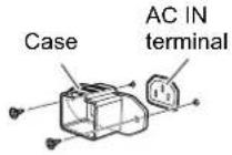
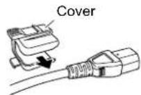
Attaching the power cord holder
The provided power cord holder prevents accidental disconnection of the AC power cord from the AC IN terminal. The power cord holder consists of two parts, a case and a cover.
1
2
3
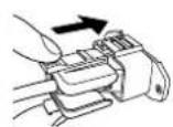
To detach the cover

CAUTION
- Use only the provided screws.
• Make sure the plug will not be pulled out after the cover is attached to the case. - The illustration above is of DT-R24L4D. When using DT-R17L4D, pay attention to the direction in which the power cord holder is attached.
Front panel

text_image
Tally lamp This lamp is controlled by the tally function of the MAKE/TRIGGER terminal. • You can select the color of the tally lamp from "GREEN" or "RED." (※"TALLY SELECT" in "FUNCTION SETTING" on page 15 and "External Control" on page 18) • "NO EFFECT" is displayed when you press a button which is not available for the current input or signal format (the lamp lights even when the function does not actually work). • The items controlled by the MAKE system cannot be controlled by the buttons on the front panel ("REMOTE ON" is displayed and the lamps do not light). The illustration of the monitor is of DT-R24L4D. DT-R17L4D 13 14 15 1 DT-R24L4D 1 2 3 4 5 6 7 8 9 10 13 14 15 11 Speakers (stereo)
The speakers emit the same audio signal emitted from the AUDIO ASSIGN (DT-R24L4D) / AUDIO (DT-R17L4D) (MONITOR OUT) terminals. (∞ " 6 AUDIO ASSIGN (DT-R24L4D) / AUDIO (DT-R17L4D) (MONITOR OUT) terminals" on page 9)
2 VOLUME adjustment knob Adjusts the volume.
3 Picture adjustment knob
PHASE: Adjusts the picture hue.
CHROMA: Adjusts the picture color density.
BRIGHT: Adjusts the picture brightness.
CONTRAST: Adjusts the picture contrast.
- PHASE and CHROMA cannot be adjusted for certain signal formats.
- When "COMPONENT PHASE" is set to "DISABLE" and an NTSC signal is input, PHASE can be adjusted (page 15).
4 MUTING button
Turns off the sound when no menu screen is displayed.
- To cancel the function, press the button again or turn the VOLUME adjustment knob.
- Muting function is also canceled when "BALANCE" of "AUDIO SETTING" in the MAIN MENU is changed (page 14).
5 ◀/▽ △ buttons
When a menu screen is displayed Selects or adjusts menu items. (The "The operation procedure" on page 12)
When no menu screen is displayed Selects the audio channels of EMBEDDED AUDIO signals. (“Audio Channel Selection” on page 11)
- Pressing <button while holding button displays the SET-UP MENU. (“The operation procedure” on page 12)
6 MENU button
Activates/deactivates the display of the MAIN MENU. (The operation procedure" on page 12)
|7| COLOR OFF button/lamp
Displays only the luminance signal. - This function does not work for RGB input signals.
8 1:1 button/lamp
Displays the picture in the original resolution of the input signal.
- The aspect ratio of the picture may change depending on the input signal.
9 AREA MARKER button/lamp Displays/hides the area marker
- Select the style of the area marker in "MARKER" of the MAIN MENU (page 13).
- This function works only when displaying the picture in 16:9 aspect ratio.
- This function does not work when "AREA MARKER" or "R-AREA MARKER" is set to "OFF" in "MARKER."
10 SAFETY MARKER button/lamp Displays/hides the safety marker.
- Adjust the area of the safety marker in "MARKER" of MAIN MENU (page 13).
- This function does not work when displaying the picture in the 1:1 mode.
- This function does not work when "SAFETY MARKER" or "R-SAFETY MARKER" is set to "OFF" in "MARKER."
11 SCREENS CHECK button/lamp
Displays only the selected element (R, G, or B) of the video signal.
• Each time you press this button, the picture changes in the following order.

12 T.C. (time code) button/lamp
Activates/deactivates the display of the time data (time code) contained in the SDI signal. (On the Information Display" on page 11)
- Select the time code type in "INFORMATION" of SET-UP MENU (page 17).
13 INPUT SELECT buttons/lamps Selects an input.
SDI 1: E. AUDIO HD/SD SDI (IN 1) terminal
SDI 2: E. AUDIO HD/SD SDI (IN 2) terminal
DVI: DVI-D (HDCP) terminal
DT-R24L4D
VIDEO 1: VIDEO (INPUT 1) terminal VIDEO 2: VIDEO (INPUT 2) terminal
DT-R17L4D
VIDEO: VIDEO terminal • The lamp for the selected input lights.
14 Power lamp
Unlit: The monitor is completely off (the power switch on the rear panel is turned off).
Lights in Green:
The monitor is on.
Lights in orange:
The monitor is off (on standby).
Flashes in orange:
The monitor is in the P. SAVE
(power save) mode. (☒ "NO SYNC ACTION" in "SYNC FUNCTION" on page 15)
15 button
Turns on and off (on standby) the monitor. • The power switch is equipped on the rear panel of the monitor ( 1 on page 8).
Audio Channel Selection
Select audio channels emitted from the speakers (L/R) and the AUDIO ASSIGN (DT-R24L4D) / AUDIO (DT-R17L4D) (MONITOR OUT) (OUT1(L)/OUT2(R)) terminals, when EMBEDDED AUDIO signals come in to the E. AUDIO HD/SD SDI terminal (IN1 or IN2) and SDI input (1 or 2) is selected.
- You have to choose a group of selectable audio channels before the channel selection. (E.AUDIO GROUP" in "AUDIO SETTING" on page 14)
- The setting is memorized for each input (SDI 1 and SDI 2).