MP15EMC62 - Microwaves MIDEA - Free user manual and instructions
Find the device manual for free MP15EMC62 MIDEA in PDF.

User questions about MP15EMC62 MIDEA
0 question about this device. Answer the ones you know or ask your own.
Ask a new question about this device
Download the instructions for your Microwaves in PDF format for free! Find your manual MP15EMC62 - MIDEA and take your electronic device back in hand. On this page are published all the documents necessary for the use of your device. MP15EMC62 by MIDEA.
USER MANUAL MP15EMC62 MIDEA
SERVICE MANUAL PTACSERIES

natural_image
Isometric line drawing of a rectangular air conditioner unit (no text or symbols)7,000-15,000 BTU/H

natural_image
Exterior view of modern glass skyscrapers with misty cityscape in the foreground (no visible text or signage)CONTENTS
- Precaution
1.1 Safety Precaution
1.2 Warning - Dimensions
- Unit Components
- Installation Details
4.1 How to Install Unit
4.2 Care and Cleaning
4.3 Other Installations - Functions and Control Panel
- Refrigerant Cycle Diagram
- Electronic Function
7.1 Terms and Definitions
7.2 Electric Control Working Environment
7.3 Protection Function
7.4 Operation of Fan Motor
7.5 Operation of Compressor
7.6 DIP Switches and Jumper Selection - Operations Characteristics
8.1 Cooling Operation
8.2 Heating Operation - Power Connection Options
- Troubleshooting
10.1 Error Display
10.2 Troubleshooting
1-3
1
1-3
3
4
5-15
5-7
7-8
9-15
16-20
21
21-25
21
22
22
22-23
24-25
25
25
25
25
25
26-27
28-33
28
28-33
1. Precaution
1.1 Safety Precaution
To prevent personal injury and/or property damage, follow the instructions below.
Failure to follow correct procedure may result in personal injury, death, and/or property damage. Before servicing unit, read this service manual.
1.2 Warning
INSTALLATION
To reduce the risk of fire or explosion, electric shock, personal injury, death, product failure, or property damage during the installation process, read and follow the warnings listed below.
- Do not use a defective or underrated circuit breaker. Use a dedicated circuit on this appliance.
- For electrical work, contact the dealer/seller, a qualified electrician, or an authorized service center. Do not disassemble or repair the product.
• Ground the product. - Securely install the panel and cover of control box.
- Avoid improper wiring or installation.
• Use the correctly rated breaker and fuse. - Do not modify or extend the power cable.
- Do not install, remove, or reinstall the unit unaccompanied.
- Be careful when unpacking and installing around exposed sharp edges, especially the casing edges and the fins on the condenser and evaporator.
- For installation, always contact the dealer or an authorized service center.
- Do not install the product on a defective installation stand.
- Be sure the installation area does not deteriorate with age to avoid the base collapsing.
- Do not let the air conditioner run for a long period of time when there is high humidity and a door or window is left open. Moisture may condense and wet or damage furniture.
- Do not pull out or damage the power cord during operation.
- Do not place anything on the power cable.
- Do not plug or unplug the power plug during operation.
- Do not touch/operate the product with wet hands.
- Do not place a heater or other appliance near the power cable.
- Do not allow water get into the electric parts.
- Do not store or use flammable gas near the product.
- Do not use the product in a confined space for a long period of time to avoid oxygen deficiency.
- If a flammable gas leaks, turn off the gas and open a window for ventilation before turning this product on. Do not use the telephone or turn switches on or off.
- If strange sounds or smoke come from product, turn the breaker off or disconnect from power
supply.
- Stop operation and close window during a storm. If possible, remove product from window.
- Do not open the product's inlet grill while in operation. If the unit has an electrostatic filter, do not touch it.
- Avoid having water enter the unit.
- If the product becomes soaked, flooded, or submerged in water, contact an authorized service center.
- Ventilate the product from time to time when operating it near a stove or other appliance.
- Turn the main power off when cleaning or troubleshooting the product.
- If the product will not be in use for a long period of time, disconnect it from the power supply or turn off the breaker. An unintended operation may occur.
- Ensure that no one can step on or fall onto the outdoor unit.
CAUTION
To reduce the risk of injury or property damage after installing product, read and follow the warnings listed below.
- Always check for gas (refrigerant) leakage after installing or repairing. Low refrigerant levels may cause product failure.
- Install drain hose to ensure water drains away properly. A bad connection may cause water leakage.
- Keep unit levelled when installing to avoid vibration or water leakage.
- Do not install product where noise or hot air from the outdoor unit can bother others or damage property.
- In order to avoid personal injury, use two or more people to lift and transport product.
- Do not install the product where it will be directly exposed to ocean breeze (salt spray). It may cause corrosion, which, particularly on the condenser and evaporator fins, could cause product malfunction or inefficient operation.
OPERATIONAL
To reduce the risk of fire or explosion, electric shock, personal injury, health issues, product failure, or property damage while the product is in operation, read and follow the warnings listed below.
- Do not sit in the draft or expose skin directly to cool air for long periods of time.
- Do not use unit for other purposes, such as preserving foods, works of art, etc., not intended for this product. It is a consumer air conditioner, not a refrigerating system.
- Do not block the inlet or outlet of airflow.
- Use a soft cloth to clean. Do not use harsh detergents, solvents, etc.
- Do not touch the metal parts of the product when removing the air filter. They are sharp.
- Always insert the filter securely. Clean the filter every two weeks or, if necessary, more since a dirty filter reduces product efficiency and could cause product malfunction or damage.
-
Do not insert hands or other object through air inlet or outlet. There are sharp, moving parts inside.
-
Do not drink the water drained from the product. It is unsanitary.
- Use a firm stool or ladder when cleaning the product.
- Replace all batteries in the remote control with new ones. Do not mix old and new batteries.
- Do not recharge or disassemble the batteries or dispose of them in a fire.
- If the liquid from the batteries touches exposed skin and/or gets on clothing, wash with clean water. Do not use the remote if the batteries have leaked.
2. Dimensions
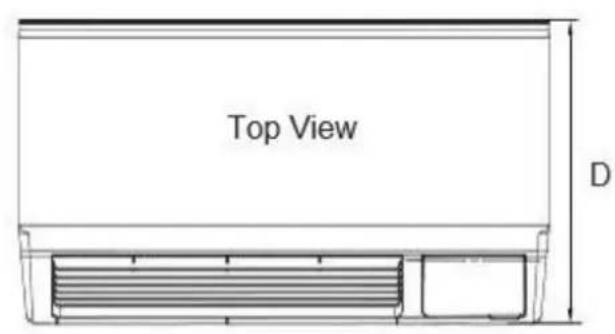
text_image
Top View D
natural_image
Technical line drawing of a heat exchanger or cooling unit with no visible text or symbolsFront View

natural_image
Pure technical line drawing of a mechanical part with no text or symbols| Dimensions | W x H x D (inches) |
| Dimension 1No sleeve, rear grille, or rear net | 42 x 15.9 x 20.9 |
| Dimension 2Includes sleeve with no rear grille and rear net | 42 x 16 x 22.8 |
| Dimension 3Includes sleeve and rear net | 42 x 16 x 23.1 |
| Dimension 4Includes sleeve, rear net, rear grille | 42 x 16 x 23.9 |
3. Unit Components

text_image
INDOOR-AIR INLET FILTERS GRILLE FRONT PANEL INDOOR COIL CHASSIS OUTDOOR GRILLE ACCESSORY SLEEVEDecomposition Figure
4. Installation Details
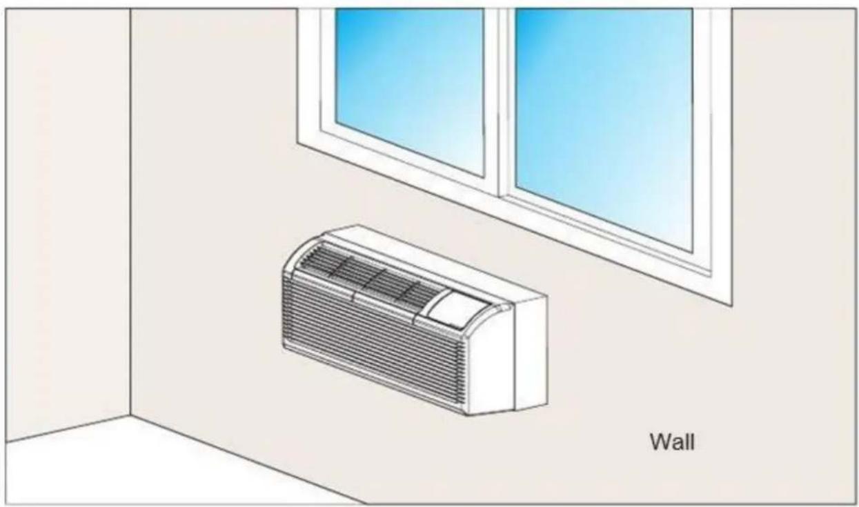
natural_image
Illustration of a wall-mounted air conditioner unit in an indoor room with a window view (no text or symbols)Installation (Fig. 1)
4.1 How to Install Unit
INSTALLATION

CAUTION
There are sharp edges that can cause serious injury.
When lifting the air conditioner, use 2 people to lift. Unit is heavy.
PREPARATION OF SLEEVE ASSEMBLY (optional)
- For an existing sleeve, measure the wall sleeve dimensions.
- Install the new air conditioner according to these installation instructions to achieve the best performance. All wall sleeves used to mount the new air conditioner must be in good structural condition and have a rear grille that securely attaches to the sleeve or the overhang of the sleeve to secure the new air conditioner.
- To avoid vibration and noise, make sure the unit is installed securely and firmly.
- When installing the sleeve, make certain there is nothing within 20 inches of the back that would interfere with heat radiation and exhaust airflow. (See Fig. 2)
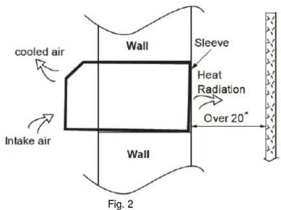
text_image
cooled air Intake air Wall Sleeve Heat Radiation Over 20° Wall Fig. 2- Refer to the installation instruction of sleeve assembly for more details.
UNIT INSTALLATION
- Carefully remove shipping tapes from the front panel. (See Fig. 3)
- Remove the front panel (see Fig. 4) by pulling out the bottom to release the tabs (A). Then lift up (B).
- Remove the shipping screw from the vent door. (See Fig. 5)
- Rotate the vent control lever to either open or close the vent door. (See Fig. 6)
Dimensions of air conditioner
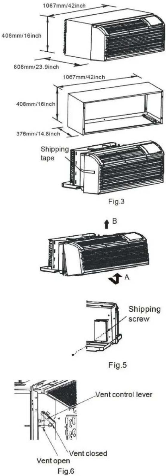
text_image
1067mm/42inch 408mm/16inch 606mm/23.9inch 1067mm/42inch 408mm/16inch 376mm/14.8inch Shipping tape Fig.3 B A Shipping screw Fig.5 Vent control lever Vent closed Vent open Fig.6UNIT INSTALLATION (CONTINUED)
- Keep unit levelled when lifting and sliding it into wall sleeve. Once it is firmly against front of wall sleeve, secure with 4 screws and washers (supplied in the Sleeve Assembly) through the unit overhang holes. (See Fig. 7 and Fig. 8)
- Reinstall front panel. (See Fig. 9) Place tabs over top rail (A). Push inward at bottom until panel snaps into place (B).
- If unit is installed where condensation drainage can drip in an undesirable location, an accessory drain kit should be installed and connected to drain system.

4.2 Care and Cleaning
FRONT PANEL AND CASE
Turn unit off and disconnect from power supply. To clean, use water and a mild detergent. Do not use bleach or abrasive materials. Some commercial cleaners may damage the plastic parts.
OUTDOOR COIL
Coil on outdoor side of unit should be checked regularly. Unit will need to be removed to inspect dirt build-up that will occur on the inside of the coil. If clogged with dirt or soot, coil should be professionally cleaned. Clean inside and outside of outdoor coils regularly.
NOTE: Never use a high-pressure spray on coil.

CAUTION
Do not put obstacles, such as window curtain, etc., around air inlet or inside of air outlet.
Always insert the filter securely, clean filter once every two week as required.
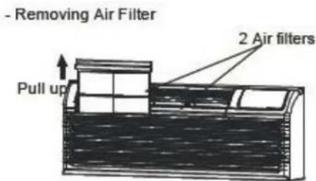
text_image
- Removing Air Filter Pull up 2 Air filtersFig.10
- Replacing Air Filter

text_image
Push downFig.11

CAUTION
UNIT DAMAGE HAZARD
Failure to follow its caution may result in equipment damage or improper operation.
Airflow restriction may cause damage to the unit.
- The most important thing do to in order to maintain unit efficiency is to clean the filters once every two weeks as required.
- Clogged filters reduce cooling, heating and airflow.
- Keeping filters clean will:
○ Decrease cost of operation,
- Save energy,
o Prevent clogged indoor coil, and
- Reduce risk of premature component failure.

CAUTION
UNIT DAMAGE HAZARD
Failure to follow this caution may result in equipment damage or improper operation.
Do not operate unit without filters in place. If a filter becomes torn or damaged, it should be replaced immediately.
Operating without filters or with damaged ones will allow dirt and dust to reach indoor coil and will reduce cooling, heating, airflow, and efficiency of unit. Airflow restriction may cause damage to unit.
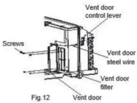
VENT DOOR FILTER
IMPORTANT: Turn unit off before cleaning
- If the vent door is open, gaining access requires removing the unit from the wall sleeve. Clean the vent filter twice a year or as required.
- Make sure to remove the shipping screw from the vent door. (See Fig.5)
- Rotate the vent control lever to open the vent door. (See Fig.6)
- Remove the four screws from the vent door filter. (See Fig.12)
- Pull out the vent door steel wire from the hole of the vent door, then take off the vent door and filter. (See Fig.12)
- Clean the filter. Dry thoroughly before replacing.
- Replace the vent door, reinstall the four screws.
• Reinsert the vent door steel wire.
- To clean air filters:
○ Vacuum off heavy soil,
- Run water through filter, and
- Dry thoroughly before replacing.
4.3 Other Installations
Optional Wired/Wireless Digital Wall Stat and EMS systems.
DIP SWITCH
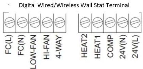
text_image
Digital Wired/Wireless Wall Stat Terminal FC(L) FC(N) LOW-FAN HI-FAN 4-WAY HEAT2 HEAT1 COMP 24V(N) 24V(L)24V WIRED CONTROL

text_image
C R Y W O/B GH GL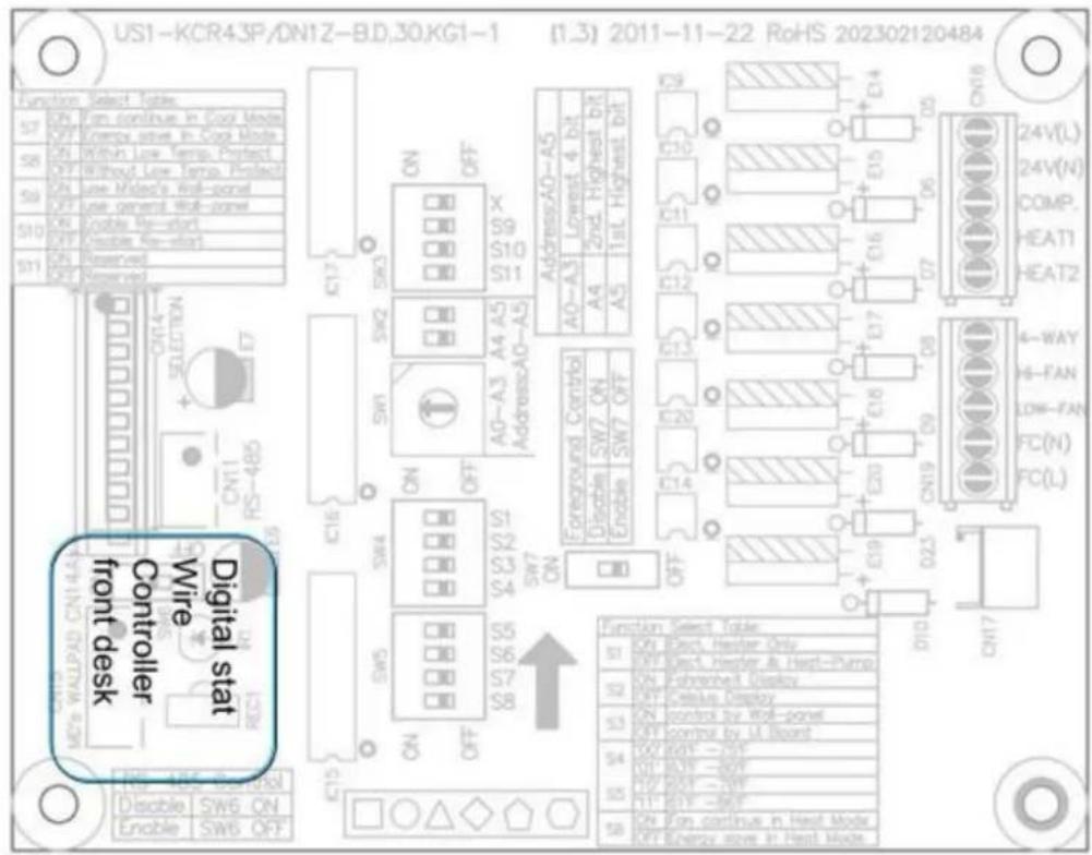
text_image
US1-KCR43P/DN1Z-BD,30KG1-1 (1.3) 2011-11-22 RoHS 202302120484 Function Select Tables S7 ON Fan continue in Dock Mode OFF Open Active drive in Dock Mode S8 ON Retina Low temp. Protect OFF Without Low temp. Protect S9 ON Use Mided's Roll-panel OFF Use general Wall-panel S10 ON Enable My-start OFF Enable No-start S11 ON Reserved OFF Reserved Digital stat Controller front desk Wire Switch ON SW5 ON Switch OFF IC16 SW4 ON SW7 ON ON SW5 ON SW8 ON IC15 IC14 IC13 IC12 IC11 IC10 Address:AD-A5 A0-A3 Lowest 4 bit A4 2nd Highest bit A5 1stL Highest bit AG-A3 A4 A5 Address:A0-A5 Foreground Control Disable SW7 ON Enable SW7 OFF IC20 IC14 IC19 IC23 ON19 ON ON23 ON ON17 ON Function Select Table ON Rect Header Only OFF Rect Heater & Heat-Pump ON Fehnred Display OFF Ceeius Display ON control by Roll-panel ON control by UL Board ON BOUT -20F ON BOUT -80F ON BOUT -NW ON BOUT -80F ON BOUT -80F ON BOUT -80F ON BOUT -80F ON BOUT -80F ON BOUT -80F ON BOUT -80F ON BOUT -80F ON BOUT -80F ON BOUT -80F ON BOUT -80F24 V controller | Front desk
Thermostat Installation
To install wired thermostat, plug it in directly to the unit as shown below:

natural_image
Digital remote control device with black cable and wiring, no visible text or symbols on the main body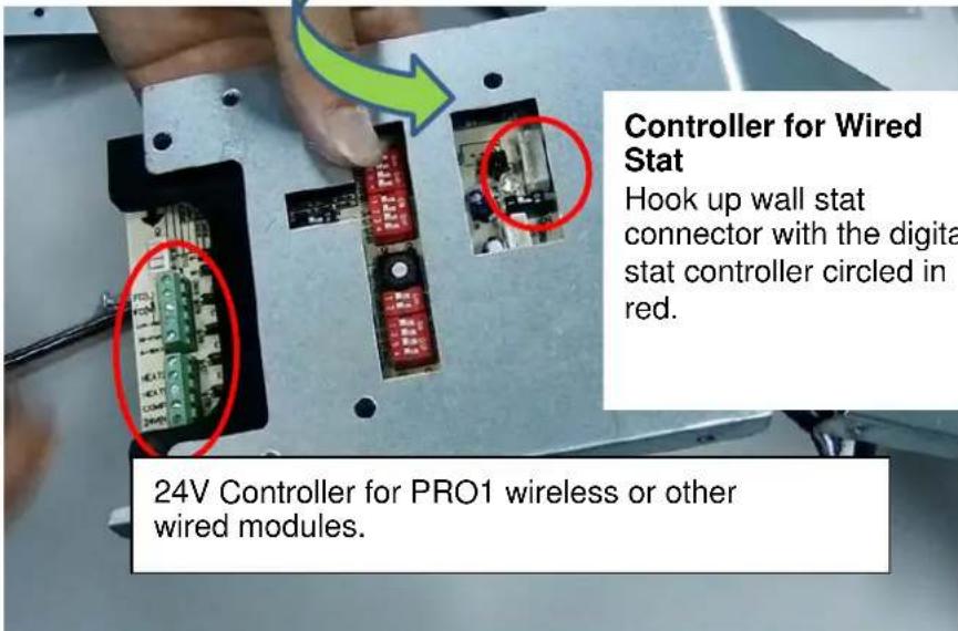
text_image
Controller for Wired Stat Hook up wall stat connector with the digit stat controller circled in red. 24V Controller for PRO1 wireless or other wired modules.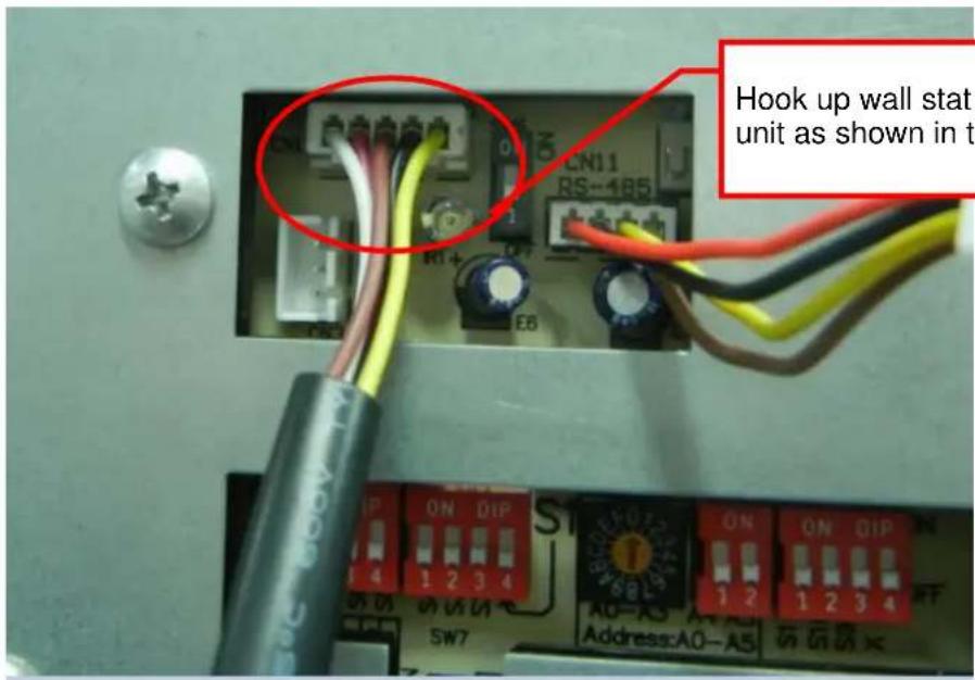
text_image
CN11 RS-185 R1+ EB Hook up wall stat unit as shown in t IP ON QIP 4 1 2 3 4 SW7 A0-A3 A4 A5 Address:A0-A5Hook up wall stat connector to the unit as shown in the image.
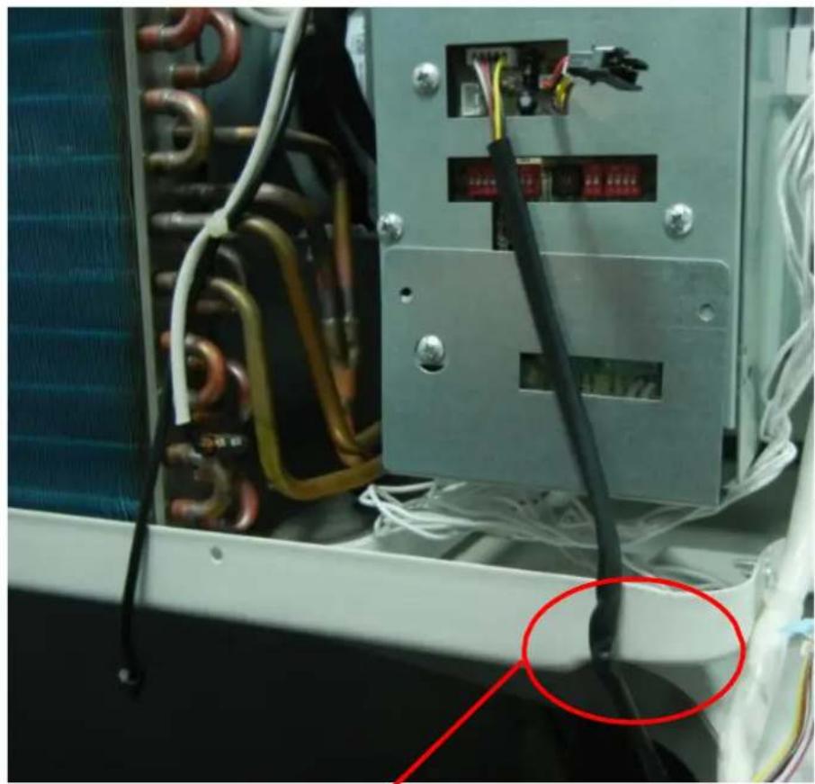
natural_image
Close-up of an electrical control panel with visible wiring and connectors, no text or symbols present.It is advisable to affix wall stat wire with tape to avoid any damage while installing the unit.
PRO1 Wireless and Wired Digital Wall Stat Configuration
Follow the steps below:
- Power OFF the unit.
- Turn OFF all the DIP switches by pushing them down.
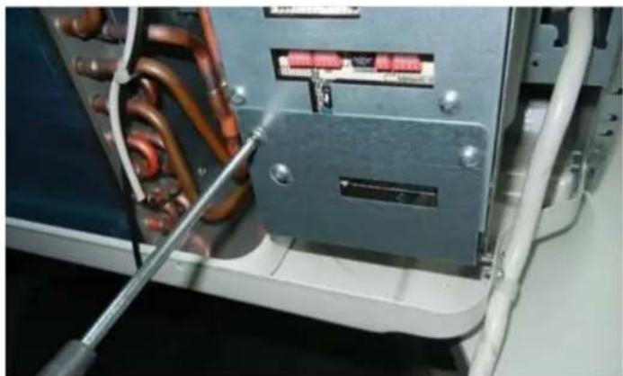
- Turn ON S3—the second switch on the second block from right—by pushing it up. Circled in red below.
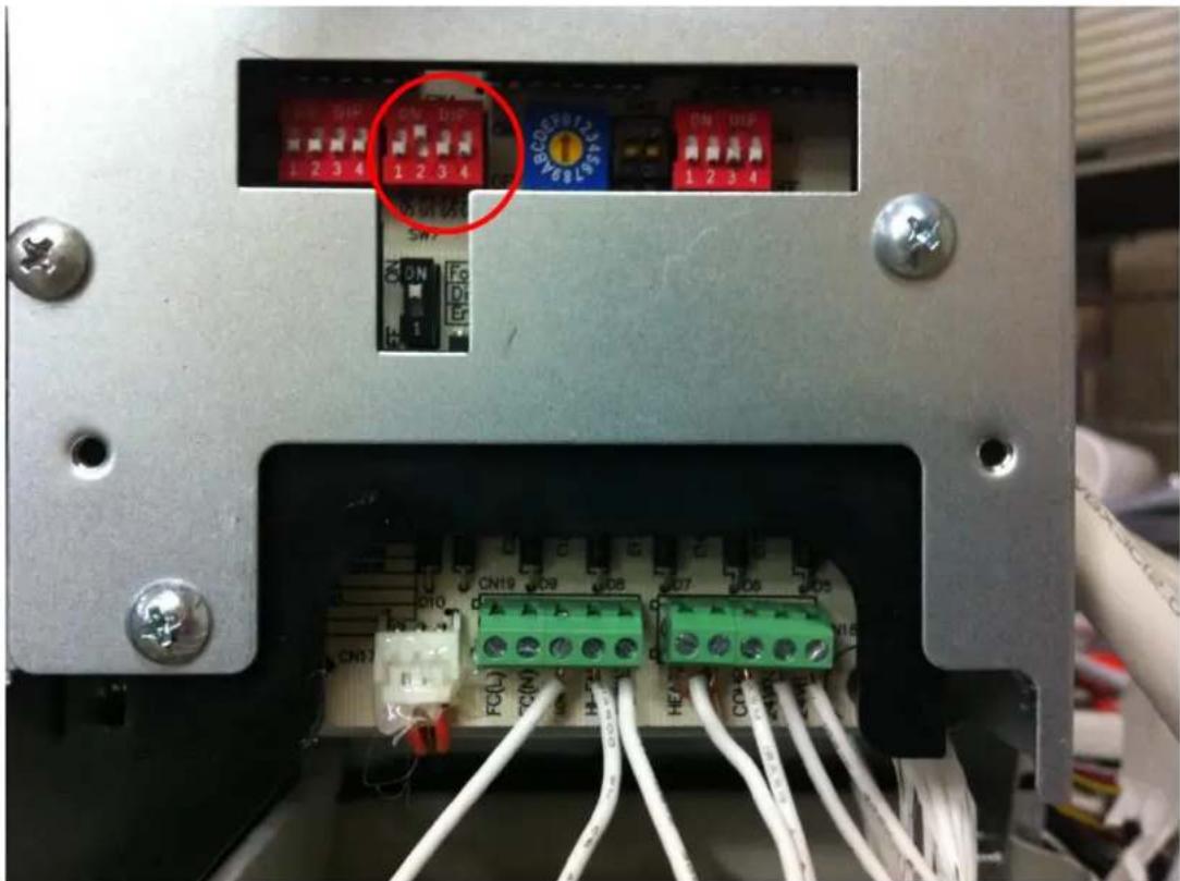
text_image
Internal panel of an electronic device showing terminal blocks, indicator lights, and wiring connections with Chinese labels.- Detach the controller cover.
natural_image
Close-up of a mechanical or electrical component with copper and orange wires, no visible text or symbols
natural_image
Interior view of an electrical control panel with copper inductors and wiring (no visible text or symbols)- Connect the wireless or wired module with controller. Use the table below as guidance.
Unit
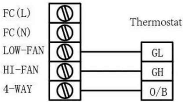
flowchart
graph TD
    A["FC (L)"] --> B["Thermostat"]
    C["FC (N)"] --> B
    D["LOW-FAN"] --> B
    E["HI-FAN"] --> B
    F["4-WAY"] --> B
    B --> G["GL"]
    B --> H["GH"]
    B --> I["O/B"]
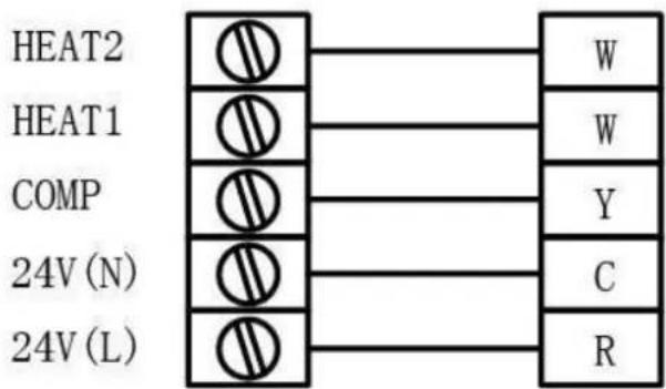
text_image
HEAT2 HEAT1 COMP 24V (N) 24V (L)
natural_image
Close-up of a hand inserting a cable into an electronic device with terminal blocks (no visible text or symbols)- Jump the connection between Heat 1 and Heat 2 as shown below.

text_image
Unit FC (L) FC (N) LOW-FAN HI-FAN 4-WAY Heat2 HEAT1 COMP 24V (N) 24V (L) R W W Y C GL GH O/B Thermostat- After connecting the stat with unit, apply double-sided tape on the back of wireless module.
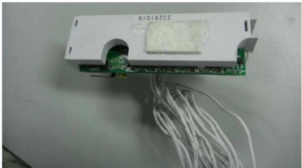
natural_image
White electronic device with green circuit board and white cable, no visible text or symbols on the main subject- Stick the module to unit as depicted below.

natural_image
Interior view of an industrial electrical enclosure with exposed circuit board and wiring (no visible text or symbols)- Set the thermostat to OFF.
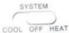
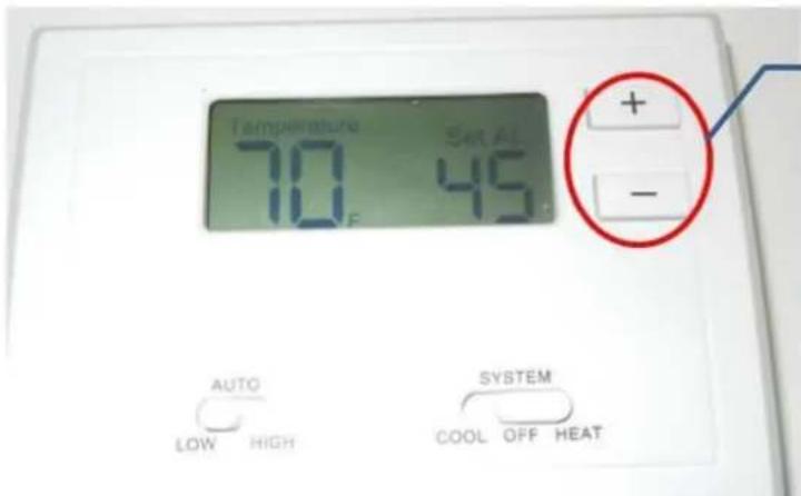
- Set CO to b on thermostat by following the procedure below:
Press and hold + and - on thermostat until it displays CA 1. Then press them again to get either CO b or CO 0.
text_image
Temperature 70°F Set AL 45°C + - AUTO LOW HIGH SYSTEM COOL OFF HEAT• If CO 0 is displayed, then press + to change it to CO.
• If CO b is displayed, then wait for the thermostat to return to temperature screen.
- Replace the cover and assemble the unit.
- Turn ON the unit and allow 3 minutes for response time.
5. Functions and Control Panel
text_image
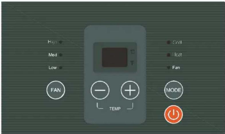
High Med Low FAN Temp Cond Icat Fan MODEThe controls featured in this manual are found in many different models. There may be slight variations.
POWER
Press the POWER button to turn the unit on or off. When the unit is on, the power indicator light will be green. When the unit is off, the light will go out.
MODE
Push this button to cycle through the modes COOL, HEAT, and FAN. The green indicator light beside a mode will illuminate, identifying which one is selected. The range of temperature setting is 62^ F – 86^ F.
- COOL: Cooling begins automatically when the ambient temperature is above the set point and stops when the ambient temperature is 4°F below the set point. However, the compressor will run at least 5 minutes in COOL mode before stopping. The fan runs in continuous mode.
- HEAT: For heat pump models, the unit can alternate to run between reverse cycle heat mode and electric heater mode, according to the difference between the set temperature and the ambient temperature. The fan motor cycles on and off with the compressor and electric heater.
• FAN: Fan operation only without heating and cooling.
NOTE: The reverse cycle and electric heater cannot run at the same time. It is normal for the reverse cycle heat mode not to operate in the following cases:
- When the outdoor temperature is lower than 40^ F or the ambient temperature falls 8^ F below the set point temperature.
- There is a 3-minute minimum compressor run time at any setting to prevent short cycling. The indoor fan motors start and stop before and after the compressor cycles off.
- When frost builds up to the evaporator coils, the unit will defrost automatically and the compressor will cycle off.
UP/DOWN BUTTONS (▲ / ▼)
Push the UP or DOWN button to increase or decrease the set temperature in cooling or heating mode. The temperature can be set by increments of 1^ . The setting temperature appears in the display.
NOTE: Press and hold ▲ and ▼ buttons simultaneously for 3 seconds to alternate the temperature display between °C and °F scale.
FAN
Push this button to change the fan speed to HIGH, MED, or LOW.
DISPLAY
Shows the set temperature in ^ C or ^ F . While on FAN-only mode, it shows the ambient temperature.
Control codes:
- LC: Pads on the control panel are not available. The unit can be set by using wire controller only.
Note: When receiving the wired remote control signal display LC. Or when wired remote control signal is not received within the panel key operation for 5 seconds to display LC
• FC: Front desk control.

text_image
Turn the switch to off. The front desk switch can be connected in two ways. FC(L) FC(N) 24V(N) 24V(L) Front desk control switch FC(L) FC(N) 24V(AC)~ Front desk control switchError codes:
• AS: Open or short circuit of ambient temperature sensor (T1).
• ES: Open or short circuit of evaporator temperature sensor (T2).
• CS: Open or short circuit of condenser temperature sensor (T3).
• OS: Open or short circuit of outside temperature sensor (T4).
• HS: Open or short circuit of exhaust temperature sensor (T5 or T6).
Other codes:
• LO: Room temperature is lower than 32^ F.
• HI: Room temperature is higher than 99°F.
- E4: Communication failure between main control board and display board.
• LE: Wire Controller mode failure
DIP Switches
Configurations and functions of each DIP switch position are explained below.

text_image
DIP Switches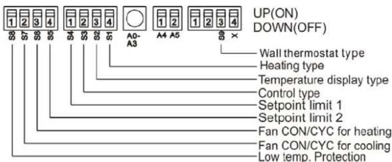
text_image
UP(ON) DOWN(OFF) Wall thermostat type Heating type Temperature display type Control type Setpoint limit 1 Setpoint limit 2 Fan CON/CYC for heating Fan CON/CYC for cooling Low temp. ProtectionDIP Switches Configurations
| No. | UP (ON) | DOWN (OFF) | Remarks |
| S1 | Electric heat only | Electric heat and pump heat | For heat pump unit only. |
| S2 | Temperature Display in °C Temperature | Temperature Display in °F | |
| S3 | Wall thermostat enable | Control panel enable | |
| S4*S5 | UP*UP: 61°F – 86°FUP*DOWN: 65°F – 78°FDOWN*UP: 63°F – 80°FDOWN*DOWN: 68°F – 75°F | Two configurations(S4*S5) combine to select set point range. | |
| S6 | Fan continuous run for heating Fan cycle for heating | ||
| S7 | Fan continuous run for cooling | Fan cycle for cooling | |
| S8 | Low temp. protection enable | Low temp. protection disable | |
| S9 | Use some types of wall thermostat | Use PTAC other wall thermostat | Consult with the sales agency or manufacturer for details. |
NOTE: On heating mode, the temperature setting can't be higher than 84°F.
- Electric Heat Only (for heat pump unit only): This setting is typically used for emergency heating.
- Wall Thermostat Enable: A wired wall thermostat can be connected to the unit. To connect a wall thermostat to the unit, this DIP switch must be moved to the Wall Thermostat Enable position in order for the wall thermostat to function.
- Set-point Temperature Limits: Provides a restricted range of temperature control.
- Heat and Cool Fan CON/CYC DIP switches: Allows the fan to operate in continuous or cycle mode while the unit is in heating or cooling mode.
Continuous (CON): Allows fan to run continuously, circulating air even when the temperature setting has been satisfied. This switch helps to maintain the ambient temperature closer to the thermostat setting.
- Cycle (CYC): This setting allows the fan to cycle on and off with the compressor or electric heater. The fan stops a short time after the set point is reached.
Functions for Front desk switch panel and Wire Controller
- Front desk switch panel: If an ON/OFF switch is connected to the ports, the A/C unit can be turned off with it. The LED display on the unit will show FC.
- Wired controller: The LED display will show LC (reserved) if a wired controller is connected. If the communication portal is one way, the buttons on the control panel will be invalid.
Note: This wired controller is optional, and it is connected to the switchboard.

flowchart
graph TD
    A["FRONT DESK SWITCH PANEL"] --> B["ROOM 100"]
    A --> C["ROOM 101"]
    A --> D["ROOM N"]
    B --> E["PTAC #1"]
    C --> F["PTAC #2"]
    D --> G["PTAC #N"]
    E --> H["Black White"]
    F --> I["Black White"]
    G --> J["Black White"]
    H --> K["FIELD-SUPPLIED 24V TRANSFORMER (SEE NOTE 1)"]
    I --> K
    J --> K
    style A fill:#f9f,stroke:#333
    style B fill:#ccf,stroke:#333
    style C fill:#ccf,stroke:#333
    style D fill:#ccf,stroke:#333
    style E fill:#cfc,stroke:#333
    style F fill:#cfc,stroke:#333
    style G fill:#cfc,stroke:#333
    style H fill:#ffc,stroke:#333
    style I fill:#ffc,stroke:#333
    style J fill:#ffc,stroke:#333
SUGGESTIONS:
- To size a transformer, use the following equation:
Quantity of PTAC units x 1 VA = Transformer Size (VA)
Example: 110 PTAC units x 1 VA = 110 VA Transformer
- Below are the American Wire Gauge (AWG) recommended sizes:
| AWG WIRE SIZE NO. | MAX. LENGTH (FT.) |
| 24 | 400 |
| 22 | 600 |
| 20 | 900 |
| 18 | 1500 |
| 16 | 2000 |
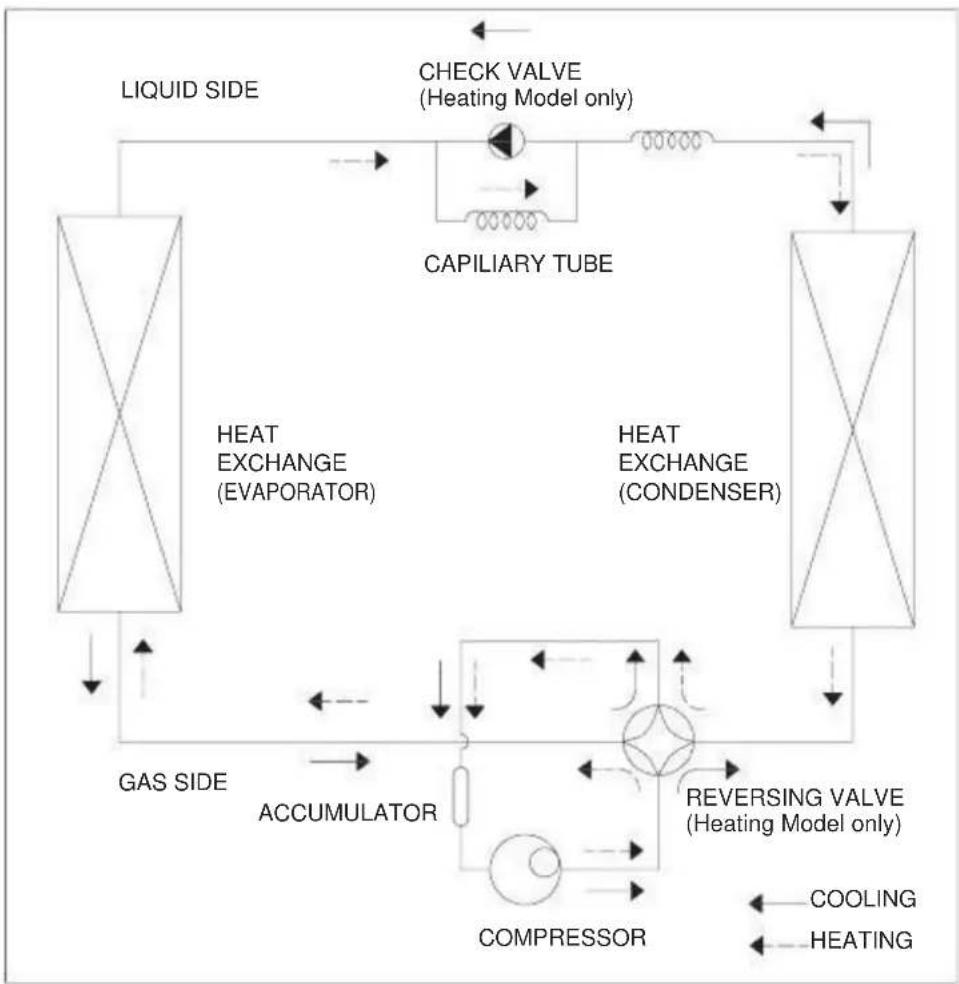
6. Refrigerant Cycle Diagram
The figure below is a brief description of the important components and their function in the refrigeration system.
This will help to explain the refrigeration cycle and the flow of the refrigerant in the Heat Pump Cycle.
flowchart
graph TD
    A["LIQUID SIDE"] --> B["HEAT EXCHANGE (EVAPORATOR)"]
    B --> C["CAPILIARY TUBE"]
    C --> D["HEAT EXCHANGE (CONDENSER)"]
    D --> E["REVERSING VALVE (Heating Model only)"]
    E --> F["COMPRESSOR"]
    F --> G["ACCUMULATOR"]
    G --> H["GAS SIDE"]
    H --> I["LIQUID SIDE"]
    I --> J["CHECK VALVE (Heating Model only)"]
    J --> K["HEAT EXCHANGE (Condenser)"]
    K --> L["REVERSING VALVE (Heating Model only)"]
    L --> M["COOLING"]
    L --> N["HEATING"]
7. Electronic Function
7.1 Terms and Definitions
• T1: Temperature of indoor ambient.
• T2: Temperature of evaporator.
• T3: Temperature of condenser.
• T4: Temperature of outdoor ambient.
• TS: Set temperature.
• DAT: Discharge air temperature.
• (T5) DAT: Discharge air temperature (T6).
7.2 Electric Control Working Environment
Input voltage: 265V, 60Hz; 230/208V, 60Hz
7.3 Protection Function
- The compressor protection functions with a delay of 3 minutes.
- Sensor protection at open or short circuit of sensor.
• Evaporator anti-freezing protection in cooling mode.
7.4 Operation of Fan Motor
7.4.1 Fan motor is on when compressor is on. Fan motor is off when compressor is off. (Except the T2 high Temp. protection.)
If there is only one speed for the fan motor, use the high speed instead of the low speed.
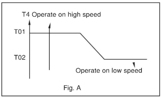
7.4.2 The fan motor operating in cooling only mode (see Fig. A).
line
| Time Point | State | Value | | :--- | :--- | :--- | | T01 | T4 Operate on high speed | High | | T02 | T4 Operate on low speed | Low |- If T4>T01 and lasts for 1 minute, the fan motor will operate at high speed.
- If T4<T02 and lasts for 1 minute, the fan motor will operate at low speed.
- If T02≤T4≤T01:
o If fan motor was initially off, it will operate at high speed.
o If fan motor was initially on, it will keep operating at initial speed.
7.4.3 The fan motor operating in heat pump and cooling mode (see Fig. B).

line
| Time | Value | |------|-------| | T03 | T03 | | T04 | T04 |- If T4≥T03 and lasts for 1 minute, the fan motor will operate at low speed.
- If T4≤T04 and lasts for 1 minute, the fan motor will operate at high speed.
- If T04<T4<T03:
o If fan motor was initially off, it will operate at high speed.
o If fan motor was initially on, it will keep operating at initialspeed.
7.4.4 The high temperature protection of evaporator at heat pump and cooling mode.

flowchart
graph TD
    A["TE7"] --> B["Compressor"]
    C["TE8"] --> D["Fan motor"]
    E["TE15"] --> F["Fan motor (low speed)"]
    G["TE9"] --> H["Compressor on Fan motor on (High/low speed is determined by T4)"]
    I["TE9"] --> J["Compressor on Fan motor on (High/low speed is determined by T4)"]
- If T2>TE7, the unit will turn the protection of compressor off, and stop this protection when T2≤TE9.
- If T2>TE8, it will turn the protection of fan motor off, and stop this protection when T2≤TE9.
- If T2>TE15, fan motor will operate at low speed by force, then stop, and determine the high or low speed according to T4.
6.4.5 At the fan only mode, the fan will keep operating and the compressor/fan motor/heater will stop operating.
7.5 Operation of Compressor
7.5.1 The compressor operating in cooling mode.

line
| Condition | Temperature (°F) | |---|---| | Compressor off | -4 | | Compressor on | +0 |T1≥Ts compressor is on T1≤Ts-4°F compressor is off
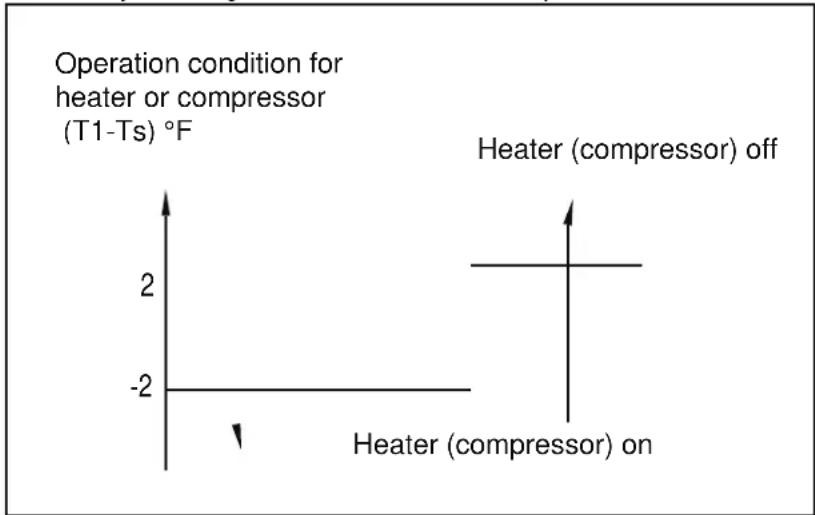
7.5.2 The compressor operating at heating mode.
There are two heating modes: (1) heat pump and (2) electric heater. The electrical heater or compressor will activate by sensing difference between set point and ambient temperature.
line
| Condition | Value | |---|---| | Heater (compressor) on | -2 | | Heater (compressor) off | 0 |7.5.2.1 The electric heater operation.
- If T1<2°F less than Ts and the fan motor is operating, 3 seconds later the heater will turn on and operate at low speed. After 30 seconds, it will change to the set speed. If the DAT temperature is higher than the protection temperature when the heater is operating, the fan motor will turn off automatically.
- If T1≥2°F more than Ts and the heater is off, and the fan motor will continue working at set speed. If the DAT temperature is lower than the protection temperature and the fan motor has been operating for more than 15 seconds, then the fan motor will turn off. If the T2 protection is triggered, the fan motor will not turn on.
7.5.2.2 The heat pump operation.
The heat pump's operation mode correlates to whether the compressor is operating. When the compressor is on and the electric heater is off, the fan motor will operate according to the anti-cold wind of heat pump. The four-way valve is always on. If T1
7.6 DIP Switches and Jumper Selection
Note: This switchboard is optional.
8. Operation Characteristics 8.1 Cooling Operation

heatmap
| Indoor air temp. °F DB | Outdoor air temp. °F DB | | ---------------------- | ----------------------- | | 50 | 68 | | 59 | 104 | | 86 | 104 |8.2 Heating Operation
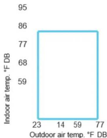
line
| Indoor air temp. °F DB | Outdoor air temp. °F DB | | ---------------------- | ----------------------- | | 86 | 77 | | 68 | 59 | | 59 | 23 | | 77 | 14 |9. Power Connection Options
Appropriate power cord accessory kit is determined by the voltage and amperage of the branch circuit. The unit does not come with a power cord (or hardwire kit). An accessory power cord must be ordered to connect the unit to an outlet. If the unit is to be hardwired, an accessory hardwire kit must be ordered.
NOTE: For 265V units, if a power cord is selected, it must plug into the 265V subbase accessory.
Cord-connected Units
The 240V field supplied outlet must match the plug for the standard 208/230V units and be within reach of the service cord. The standard cord-connected 265V units require an accessory electrical subbase for operation.
Power Cord Protection
The power cord for 230/208v units provide power cord fire protection. The unit's power automatically disconnects when unsafe conditions are detected. Power to the unit can be restored by pressing the reset button on plug. Upon completion of unit installation for 230/208V models, an operational check should be performed using the TEST/RESET buttons on the plug.
NOTE: The 265V models do not incorporate this feature as they require use of the electrical subbase accessory. Our subbase accessory is being developed.
| Power Plug |  | 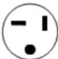 |  |  | 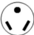 |  |  |
| Power Supply | 230V, 15A | 230V, 20A | 230V, 30A | 265V, 15A | 265V, 20A | 265V, 30A | 120V, 15A |
The appearance of the power plug will differ depending on the supplier.
Power Connection Chart
| UNIT MODEL | CODE OF POWER SUPPLY KIT | ||
| 15A 20A 30A | |||
| 208 / 230 V | 208 / 230 V | 208 / 230 V | |
| MWDUP-07AEN1-MK9 | 6-15P(15A / 240V) | 6-20P(20A / 240V) | |
| MWDUP-07EEN1-MK9 | |||
| MWDUP-09AEN1-MK3 | 6-20P(20A / 240V) | ||
| MWDUP-09EEN1-MK3 | |||
| MWDUP-12AEN1-MJ5 | 6-30P(30A / 240V) | ||
| MWDUP-12EEN1-MJ7 | |||
| MWDUP-15AEN1-MI6 | |||
| MWDUP-15EEN1-MI5 | |||
| 265 V 265 V | |||
| MWDUP-07AEN1-UK9 | 7-20P(20A / 277V) | ||
| MWDUP-07EEN1-UK9 | |||
| MWDUP-09AEN1-UK3 | |||
| MWDUP-09EEN1-UK3 | |||
| MWDUP-12AEN1-UJ5 | 7-30P(30A / 277V) | ||
| MWDUP-12EEN1-UJ7 | |||
| MWDUP-15AEN1-UI6 | |||
| MWDUP-15EEN1-UI5 | |||
| 115V | |||
| MWEUP-09EEN1-BK3 | 5-15P(15A / 120V) | ||
| MWEUP-12EEN1-BJ7 | |||
10. Troubleshooting
10.1 Error Display
| Codes | Explanations |
| AS | Open or short circuit of T1 temperature sensor |
| ES | Open or short circuit of T2 temperature sensor |
| CS | Open or short circuit of T3 temperature sensor |
| OS | Open or short circuit of T4 temperature sensor |
| HS | Open or short circuit of T5 or T6 temperature sensor |
| Lo | Temperature is lower than display range (32°F) |
| HI | Temperature is higher than display range (99°F) |
| E4 | Communication malfunction between main control board and display board |
| LE | Drive-by-wire control failure |
10.2 Troubleshooting
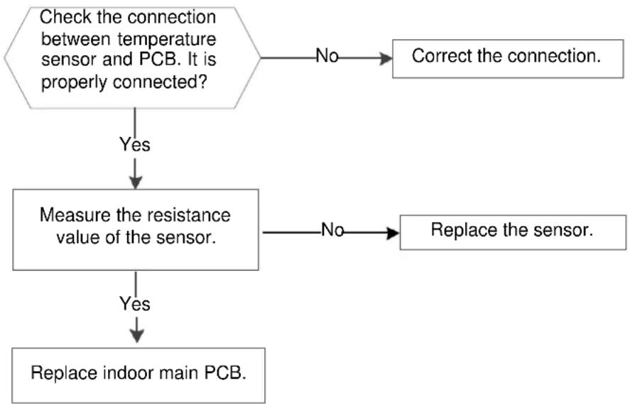
10.2.1 Open circuit or short circuit of temperature sensor diagnosis and solution (AS/E5/CS/oS/HS).
| Error Code: | AS/ES/CS/OS/HS |
| Malfunctioning conditions: | If the sampling voltage is lower than 0.06V or higher than 4.94V, the LED will display the failure. |
| Possible causes: | Wiring mistakeFaulty sensorFaulty PCB |
Troubleshooting:
flowchart
graph TD
    A["Check the connection between temperature sensor and PCB. It is properly connected?"] -->|No| B["Correct the connection."]
    A -->|Yes| C["Measure the resistance value of the sensor."]
    C -->|No| D["Replace the sensor."]
    C -->|Yes| E["Replace indoor main PCB."]

text_image
T5/T T4 T3 T2 T1 ACL (or L2) P10 P11 P08 P09 P06 P07 ACL (or L1) HEATER2-L 01.01 2014-10-9 Res HEATER2-N or COMP-N CD JD-3 RX 94V-0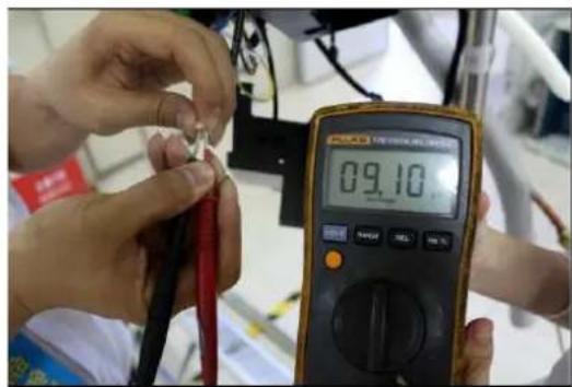
text_image
09.1010.2.2 Communication malfunction between main control board and display board (E4).
| Error Code: | E4 |
| Malfunctioning conditions: | Main control board does not receive feedback from display board during 120 seconds. |
| Possible causes: | Wiring errorFaulty display boardFaulty main control board |
Troubleshooting:
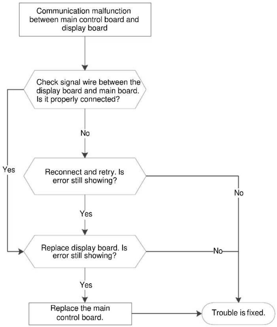
flowchart
graph TD
    A["Communication malfunction between main control board and display board"] --> B{Check signal wire between the display board and main board. Is it properly connected?}
    B -->|No| C["Reconnect and retry. Is error still showing?"]
    B -->|Yes| D["Replace display board. Is error still showing?"]
    C -->|No| E["Trouble is fixed."]
    C -->|Yes| D
    D -->|No| E
    D -->|Yes| F["Replace the main control board."]
10.2.3 Drive-by-wire controller failure (LE).
| Error Code: | LE |
| Malfunctioning conditions: | 1. Electric heating signal or compressor signal is on, but fan signal is off.2. Electric heating and compressor signals are on, but 4-way valve signal is off.3. Cooling only models have heating signal, or the 4-way valve and compressor signals are on at the same time. |
| Possible causes: | Wiring errorFaulty wire controllerWire controller doesn't match |
Troubleshooting:

flowchart
graph TD
    A["Drive-by-wire controller failure."] --> B["Electric heating and compressor are on, but 4-way valve is off."]
    B -->|No| C["Electric heating or compressor is on, but fan is off."]
    C -->|Yes| D["Is wiring between controller and DIP switch board correct?"]
    C -->|No| E["Compressor and heating or 4-way valve signals are simultaneously on."]
    D -->|Yes| F["Wire controller does not match. Change the wire controller."]
    D -->|No| G["Reconnect."]
    E -->|Yes| H["Is wiring between controller and DIP switch board correct?"]
    E -->|No| I["Reconnect."]
    H -->|Yes| J["4-way valve is set wrong."]
    H -->|No| K["4-way valve is set wrong."]
    I --> L["Wire controller is set wrong."]
| DIP Switch Terminal | Designation | 24V Controller |
| FC(L) | Front desk control terminal L | |
| FC(N) | Front desk control terminal N | |
| LOW-FAN | Low fan speed | GL |
| HI-FAN | High fan speed | GH |
| 4-WAY | 4-way valve(for heat pump model) | B |
| HEAT2 | Electrical heater 2 | W |
| HEAT1 | Electrical heater 1 | (W) |
| COMP | Compressor | Y |
| 24V(N) | 24VAC terminal N COM | C |
| 24V(L) | 24VAC terminal L | R |
| Possible Causes | Solutions |
| UNIT DOES NOT STARTUnit is unplugged.Blown fuse.Tripped circuit breaker.Unit is turned off.Unit is in a protection mode. | Check that plug is securely connected to outlet.Note: Plug has a test/reset button on it. Make sure that the plug has not tripped.Replace fuse. See Note 1 below.Reset circuit breaker. See Note 1 below.Turn unit on (bottom right button on keypad). |
| UNIT NOT COOLING/HEATING ROOMAir discharge section is blocked.Temperature setting is not high or low enough.Note: Setpoint limits might not allow unit to heat or cool the room to the temperature desired. Check section on DIP switch settings.Air filters are dirty.Room is excessively hot or cold when unit starts.Vent door left open.Unit may be in a protection mode.Compressor is in a time delay. | Make sure curtains, blinds, and/or furniture are not restricting or blocking unit's airflow.Reset to a lower or higher temperature setting.Remove and clean filters.Allow sufficient amount of time for unit to heat or cool the room.Start heating or cooling before outdoor temperature, cooking heat, or people make room uncomfortable.Close vent door.Check DIP switch settings for desired comfort.Wait approximately 3 minutes for compressor to start. |
| DISPLAY HAS STRANGE NUMBERS/CHARACTERS ON IT | The unit may be in a protection mode.The unit may have been set for °C instead of °F. |
| UNIT MAKING NOISES | Clicking, gurgling, and whooshing noises are normal during operation. |
| WATER DRIPPING OUTSIDE | If a drain kit has not been installed, condensation runoff during hot and humid weather is normal. See Note 2 below.If a drain kit has been installed and is connected to a drain system, check gaskets and fittings around drain for leaks and plug them. |
| WATER DRIPPING INSIDEWall sleeve is not installed properly. | Wall sleeve must be installed correctly for proper drainage of condensation. Check that installation is levelled and make any necessary adjustments. |
| ICE OR FROST FORMS ON INDOOR COILLow outdoor temperature.Dirty filters. | When outdoor temperature is approximately 55°F or below, frost may form on the indoor coil when unit is in Cooling mode. Switch unit to FAN operation until ice or frost melts.Remove and clean filters. |
| COMPRESSOR PROTECTIONPower may have cycled, so compressor is in a restart protection. | Random Compressor Restart: Whenever the unit is plugged in or power has been restarted, a random compressor restart will occur. After a power outage, the compressor will restart after approximately 3 minutes.Compressor Protection: To prevent short cycling of compressor, there is a random startup delay of 3 minutes and a minimum compressor run time of 3 minutes. |
NOTES
- If circuit breaker is tripped or fuse is blown more than once, contact a qualified electrician.
- If unit is installed where condensation drainage could drip in an undesirable location, an accessory drain kit should be installed and connected to drain system.
Characteristics of Temperature Sensor
| Temp. °C/°F | Resistance KΩ | Temp. °C/°F | Resistance KΩ | Temp. °C/°F | Resistance KΩ |
| -10/14 62.2756 | 17/62 | 14.6181 | 44/111 | 4.3874 | |
| -9 /15.8 58.7079 | 18/64 | 13.918 | 45/113 | 4.2126 | |
| -8 /17.6 56.3694 | 19/66 | 13.2631 | 46/115 | 4.0459 | |
| -7 /19.4 52.2438 | 20/68 | 12.6431 | 47/117 | 3.8867 | |
| -6 /21.2 49.3161 | 21/70 | 12.0561 | 48/118 | 3.7348 | |
| -5 /23 46.5725 | 22/72 | 11.5 | 49/120 | 3.5896 | |
| -4 /24.8 44 | 23/73 | 10.9731 | 50/122 | 3.451 | |
| -3 / 26.6 41.5878 | 24/75 | 10.4736 | 51/124 | 3.3185 | |
| -2 / 28.4 39.8239 | 25/77 | 10 | 52/126 | 3.1918 | |
| -1 /30.2 37.1988 | 26/79 | 9.5507 | 53/127 | 3.0707 | |
| 0 /32 35.2024 | 27/81 | 9.1245 | 54/129 | 2.959 | |
| 1 /33.8 33.3269 | 28/82 | 8.7198 | 55/131 | 2.8442 | |
| 2 /35.6 31.5635 | 29/84 | 8.3357 | 56/133 | 2.7382 | |
| 3 /37.4 29.9058 | 30/86 | 7.9708 | 57/135 | 2.6368 | |
| 4 /39.2 28.3459 | 31/88 | 7.6241 | 58/136 | 2.5397 | |
| 5 /41 26.8778 | 32/90 | 7.2946 | 59/138 | 2.4468 | |
| 6 /42.8 25.4954 | 33/91 | 6.9814 | 60/140 | 2.3577 | |
| 7 /44.6 24.1932 | 34/93 | 6.6835 | 61/142 | 2.2725 | |
| 8 /46.4 22.5662 | 35/95 | 6.4002 | 62/144 | 2.1907 | |
| 9 /48.2 21.8094 | 36/97 | 6.1306 | 63/145 | 2.1124 | |
| 10 /50 20.7184 | 37/99 | 5.8736 | 64/147 | 2.0373 | |
| 11 /51.8 19.6891 | 38/100 | 5.6296 | 65/149 | 1.9653 | |
| 12 /53.6 18.7177 | 39/102 | 5.3969 | 66/151 | 1.8963 | |
| 13 /55.4 17.8005 | 40/104 | 5.1752 | 67/153 | 1.830 | |
| 14 /57.2 16.9341 | 41/106 | 4.9639 | 68/154 | 1.7665 | |
| 15 /59 16.1156 | 42/108 | 4.7625 | 69/156 | 1.7055 | |
| 16 /60.8 15.3418 | 43/109 | 4.5705 | 70/158 | 1.6469 |

GD Midea Air-Conditioning Equipment
Co.,Ltd RAC Overseas Sales Company
Midea headquarter building, No.6 Midea Avenue
Beijiao, ShunDe, Foshan, GuangDong, P.R.C, 528311
Website: www.mideaaircon.com