
RS100-E4/PI2 - Server ASUS - Free user manual and instructions
Find the device manual for free RS100-E4/PI2 ASUS in PDF.

| Product Type | 1U Rackmount Server |
| Dimensions (L x W x H) | 381 mm x 430 mm x 43.6 mm |
| Net Weight | 6.5 kg |
| Power Supply | 300W single, 100-240V, 50-60Hz |
| Motherboard | ASUS P5M2-M/RS100-E4 |
| Chipset | Intel Xeon 3000 (Mukilteo-2) + ICH7R |
| Processor | LGA775 Intel Xeon 3000 series, EM64T, EIST |
| Memory | 4x DDR2 DIMM slots, up to 8GB unbuffered ECC/non-ECC, 533/667 MHz |
| Storage | 2x SATA II via ICH7R (RAID 0, 1), 1x IDE for optical drive |
| LAN | Dual Broadcom BCM5721 Gigabit Ethernet |
| VGA | XGI Volari Z7 PCI with 32 MB |
| Management | ASWM 2.0 (web-based); optional ASMB3-SOL IPMI 2.0 |
| Expansion Slots | 1x PCI-E x8 (via riser), 1x SO-DIMM for management card |
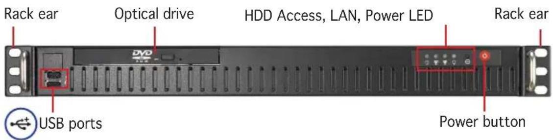
| Front Panel | Power button, reset button, 2x USB 2.0, optical drive bay (optional), LEDs (power, HDD, LAN) |
| Rear Panel | PS/2 keyboard/mouse, 2x USB 2.0, parallel, serial (COM1), VGA, 2x RJ-45 LAN, power socket |
| Safety Features | Electrical safety warnings, lithium battery caution, heavy system handling advice |
| Maintenance | Clean with dry cloth; avoid liquids. Refer to manual for component installation/removal |
| Spare Parts & Repairability | Replaceable: CPU heatsink, system blower, SATA drives, ODD, power supply. Qualified service only |
| Supported OS | Windows 2000/2003 Server, Red Hat Enterprise 3.0/4.0, SuSE Linux Enterprise Server 9.0 |
Frequently Asked Questions - RS100-E4/PI2 ASUS
User questions about RS100-E4/PI2 ASUS
0 question about this device. Answer the ones you know or ask your own.
Ask a new question about this device
Download the instructions for your Server in PDF format for free! Find your manual RS100-E4/PI2 - ASUS and take your electronic device back in hand. On this page are published all the documents necessary for the use of your device. RS100-E4/PI2 by ASUS.
USER MANUAL RS100-E4/PI2 ASUS
natural_image
Front view of a black DVD rack with multiple drive bays and indicator lights (no visible text or symbols)E2872
First Edition V1
October 2006
Copyright 2006© ASUSTeK COMPUTER INC. All Rights Reserved.
No part of this manual, including the products and software described in it, may be reproduced, transmitted, transcribed, stored in a retrieval system, or translated into any language in any form or by any means, except documentation kept by the purchaser for backup purposes, without the express written permission of ASUSTeK COMPUTER INC. ("ASUS").
ASUS provides this manual “as is” without warranty of any kind, either express or implied, including but not limited to the implied warranties or conditions of merchantability or fitness for a particular purpose. In no event shall ASUS, its directors, officers, employees, or agents be liable for any indirect, special, incidental, or consequential damages (including damages for loss of profits, loss of business, loss of use or data, interruption of business and the like), even if ASUS has been advised of the possibility of such damages arising from any defect or error in this manual or product.
Specifications and information contained in this manual ae furnished for informational use only, and are subject to change at any time without notice, and should not be construed as a commitment by ASUS. ASUS assumes no responsibility or liability for any errors or inaccuracies that may appear in this manual, including the products and software described in it.
Product warranty or service will not be extended if: (1) the product is repaired, modified or altered, unless such repair, modification of alteration is authorized in writing by ASUS; or (2) the serial number of the product is defaced or missing.
Products and corporate names appearing in this manual may or may not be registered trademarks or copyrights of their respective companies, and are used only for identification or explanation and to the owners' benefit, without intent to infringe.
Contents
Notices ......vii
Federal Communications Commission Statement ......vii
Canadian Department of Communications Statement ......vii
Safety information ......viii
Electrical Safety ......viii
Operation Safety......viii
Chapter 1: Product introduction
1.1 System package contents 1-2
1.2 System specifications 1-3
1.3 Front panel features 1-4
1.4 Rear panel features 1-4
1.5 Internal features 1-5
1.6 LED information 1-6
1.6.1 Front panel LEDs 1-6
1.6.2 Rear panel LEDs 1-6
Chapter 2: Hardware setup
2.1 Chassis cover 2-2
2.1.1 Removing the cover 2-2
2.1.2 Installing the cover 2-3
2.2 Motherboard information 2-5
2.3 Central Processing Unit (CPU) 2-6
2.3.1 Installing the CPU 2-6
2.3.2 Installing the CPU heatsink 2-8
2.4 System memory 2-10
2.4.1 Overview 2-10
2.4.2 Memory configurations 2-10
2.4.3 Installing a DIMM 2-11
2.4.4 Removing a DIMM 2-11
2.5 Replaceable components 2-12
2.5.1 Installing the air-duct 2-12
2.5.2 Installing Serial ATA drives.... 2-14
2.5.3 Installing optical disk drive (ODD) 2-17
Contents
Chapter 3: Installation options
3.1 Rackmount rail kit items 3-2
3.2 Attaching the rack ears 3-2
3.3 Attaching the rails to the rack 3-3
Chapter 4: Motherboard Info
4.1 Motherboard overview 4-2
Layout contents 4-3
4.2 Jumpers 4-5
4.3 Connectors 4-10
4.3.1 Rear panel connectors 4-10
4.3.2 Internal connectors 4-11
Chapter 5: BIOS Setup
5.1 Managing and updating your BIOS 5-2
5.1.1 Creating a bootable floppy disk 5-2
5.1.2 AFUDOS utility 5-3
5.1.3 ASUS CrashFree BIOS 2 utility 5-6
5.1.4 ASUS Update utility 5-8
5.2 BIOS setup program 5-11
5.2.1 BIOS menu screen 5-12
5.2.2 Menu bar 5-12
5.2.3 Navigation keys 5-12
5.2.4 Menu items 5-13
5.2.5 Sub-menu items 5-13
5.2.6 Configuration fields 5-13
5.2.7 Pop-up window 5-13
5.2.8 Scroll bar 5-13
5.2.9 General help 5-13
5.3 Main menu 5-14
5.3.1 System Time 5-14
5.3.2 System Date 5-14
5.3.3 Legacy Diskette A 5-14
5.3.4 Primary, Third, Fourth IDE Master/Slave 5-15
5.3.5 IDE Configuration 5-16
5.3.6 System Information.... 5-18
Contents
5.4 Advanced menu 5-19
5.4.1 USB Configuration 5-19
5.4.2 MPS Configuration 5-20
5.4.3 Remote Access Configuration 5-21
5.4.4 Trusted Computing 5-22
5.4.5 CPU Configuration 5-23
5.4.6 Chipset Configuration 5-24
5.4.7 Onboard Devices Configuration 5-26
5.4.8 PCI PnP 5-27
5.5 Power Configuration.... 5-28
5.5.1 APM Configuration 5-28
5.5.2 Hardware Monitor 5-30
5.6 Boot menu 5-31
5.6.1 Boot Device Priority 5-32
5.6.2 Hard Disk Drives 5-32
5.6.3 Boot Settings Configuration 5-33
5.6.4 Security 5-34
5.7 Exit menu 5-37
Chapter 6: RAID Configuration
6.1 RAID configurations 6-2
6.1.1 RAID definitions 6-2
6.1.2 Installing Serial ATA hard disks 6-3
6.1.3 Setting the RAID item in BIOS 6-3
6.1.4 RAID configuration utility 6-3
6.2 Intel ^® Matrix Storage Manager Option ROM Utility 6-4
6.2.1 Creating a RAID 0 set (striped) 6-5
6.2.2 Creating a RAID 1 set (mirrored) 6-7
6.2.3 Deleting a RAID set 6-8
6.2.4 Resetting Disks to Non-RAID 6-9
6.2.5 Exiting the Intel ^® Matrix Storage Manager utility .... 6-9
6.2.6 Rebuilding the RAID 6-10
6.2.7 Setting the Boot array in the BIOS Setup Utility... 6-11
6.3 LSI Logic Embedded SATA RAID Setup Utility 6-12
6.3.1 Creating a RAID set 6-13
Contents
6.3.2 Adding or viewing a RAID configuration 6-19
6.3.3 Initializing the logical drives 6-22
6.3.5 Checking the drives for data consistency 6-29
6.3.6 Deleting a RAID configuration 6-32
6.3.7 Selecting the boot drive from a RAID set 6-33
6.3.8 Enabling the WriteCache 6-34
6.4 Global Array Manager 6-34
Chapter 7: Driver installation
7.1 RAID driver installation 7-2
7.1.1 Creating a RAID driver disk 7-2
7.1.2 Installing the RAID controller driver 7-3
7.2 LAN driver installation 7-13
7.2.1 Windows ^® 2000/2003 Server 7-13
7.2.2 Red Hat ^® Enterprise ver. 3.0 7-14
7.3 VGA driver installation 7-15
7.3.1 Windows ^® 2000 Server 7-15
7.3.2 Windows ^® 2003 Server 7-16
7.3.3 Red Hat ^® Enterprise ver. 3.0 7-16
7.4 Management applications and utilities installation 7-17
7.4.1 Running the support CD 7-17
7.4.2 Drivers menu 7-17
7.4.3 Management Software menu 7-18
7.4.4 Utilities menu 7-18
7.4.5 Contact information 7-19
Appendix
A.1 Intel ^ EM64T A-2
Using the Intel ^® EM64T feature ...... A-2
A.2 Enhanced Intel Speedstep ^ Technology (EIST)...... A-2
A.2.1 System requirements ...... A-2
A.2.2 Using EIST A-3
Notices
Federal Communications Commission Statement
This device complies with Part 15 of the FCC Rules. Operation is subject to the following two conditions:
• This device may not cause harmful interference, and
- This device must accept any interference received including interference that may cause undesired operation.
This equipment has been tested and found to comply with the limits for a Class A digital device, pursuant to Part 15 of the FCC Rules. These limits are designed to provide reasonable protection against harmful interference in a residential installation. This equipment generates, uses and can radiate radio frequency energy and, if not installed and used in accordance with manufacturer's instructions, may cause harmful interference to radio communications. However, there is no guarantee that interference will not occur in a particular installation. If this equipment does cause harmful interference to radio or television reception, which can be determined by turning the equipment off and on, the user is encouraged to try to correct the interference by one or more of the following measures:
- Reorient or relocate the receiving antenna.
- Increase the separation between the equipment and receiver.
- Connect the equipment to an outlet on a circuit different from that to which the receiver is connected.
- Consult the dealer or an experienced radio/TV technician for help.

WARNING! The use of shielded cables for connection of the monitor to the graphics card is required to assure compliance with FCC regulations. Changes or modifications to this unit not expressly approved by the party responsible for compliance could void the user's authority to operate this equipment.
Canadian Department of Communications Statement
This digital apparatus does not exceed the Class A limits for radio noise emissions from digital apparatus set out in the Radio Interference Regulations of the Canadian Department of Communications.
This Class A digital apparatus complies with Canadian ICES-003.
Safety information
Electrical Safety
- Before installing or removing signal cables, ensure that the power cables for the system unit and all attached devices are unplugged.
- To prevent electrical shock hazard, disconnect the power cable from the electrical outlet before relocating the system.
- When adding or removing any additional devices to or from the system, ensure that the power cables for the devices are unplugged before the signal cables are connected. If possible, disconnect all power cables from the existing system before you add a device.
- If the power supply is broken, do not try to fix it by yourself. Contact a qualified service technician or your dealer.
Operation Safety
- Any mechanical operation on this server must be conducted by certified or experienced engineers.
- Before operating the server, carefully read all the manuals included with the server package.
- Before using the server, make sure all cables are correctly connected and the power cables are not damaged. If any damage is detected, contact your dealer as soon as possible.
- To avoid short circuits, keep paper clips, screws, and staples away from connectors, slots, sockets and circuitry.
- Avoid dust, humidity, and temperature extremes. Place the server on a stable surface.

This product is equipped with a three-wire power cable and plug for the user's safety. Use the power cable with a properly grounded electrical outlet to avoid electrical shock.
Lithium-Ion Battery Warning
CAUTION! Danger of explosion if battery is incorrectly replaced. Replace only with the same or equivalent type recommended by the manufacturer. Dispose of used batteries according to the manufacturer's instructions.
CD-ROM Drive Safety Warning
CLASS 1 LASER PRODUCT
Heavy System
CAUTION! This server system is heavy. Ask for assistance when moving or carrying the system.
About this guide
Audience
This user guide is intended for system integrators, and experienced users with at least basic knowledge of configuring a server.
Contents
This guide contains the following parts:
-
Chapter 1: Product Introduction This chapter describes the general features of the server, including sections on front panel and rear panel specifications.
-
Chapter 2: Hardware setup This chapter lists the hardware setup procedures that you have to perform when installing or removing system components.
-
Chapter 3: Installation options This chapter describes how to install optional components into the barebone server.
-
Chapter 4: Motherboard information This chapter gives information about the motherboard that comes with the server. This chapter includes the motherboard layout, jumper settings, and connector locations.
-
Chapter 5: BIOS information This chapter tells how to change system settings through the BIOS Setup menus and describes the BIOS parameters.
-
Chapter 6: RAID configuration This chapter tells how to change system settings through the BIOS Setup menus. Detailed descriptions of the BIOS parameters are also provided.
7 Chapter 7: Driver installation This chapter provides instructions for installing the necessary drivers for different system components.
- Appendix: Reference information This appendix includes additional information that you may refer to when configuring the motherboard.
Conventions
To make sure that you perform certain tasks properly, take note of the following symbols used throughout this manual.

WARNING: Information to prevent injury to yourself when trying to complete a task.

CAUTION: Information to prevent damage to the components when trying to complete a task.

IMPORTANT: Instructions that you MUST follow to complete a task.

NOTE: Tips and information to aid in completing a task.
Typography
Bold text Indicates a menu or an item to select.
Italics Used to emphasize a word or a phrase.
Example:
Example:
Command Means that you must type the command exactly as shown, then supply the required item or value enclosed in brackets.
Example: At the DOS prompt, type the
command line:
format A:/S
References
Refer to the following sources for additional information, and for product and software updates.
- ASUS Server Web-based Management (ASWM) user guide
This manual tells how to set up and use the proprietary ASUS server management utility.
- ASUS websites
The ASUS websites worldwide provide updated information for all ASUS hardware and software products. Refer to the ASUS contact information.
Chapter 1
This chapter describes the general features of the chassis kit. It includes sections on front panel and rear panel specifications.
product integration
1.1 System package contents
Check your system package for the following items.
Chassis ASUS R09 1U rackmount chassis
Motherboard ASUS P5M2-M/RS100-E4 motherboard
Components 300W Single power supply
1 x Optical drive (Optional)
1 x CPU heatsink
1 x Heatsink plastic cover
Cables AC power cable
System cables
Pre-connected device/power cables
Accessories Rackmount rail kit (Optional)
RS100-E4/PI2 user guide
RS100-E4/PI2 support CD (includes ASWM*)
CA Anti-virus software CD
R09 chassis ears (left, right)
Bag of screws
* ASUS System Web-based Management

Contact your dealer immediately if any of the items is damaged or missing.
1.2 System specifications
The ASUS RS100-E4/PI2 is a 1U barebone server system featuring the ASUS P5M2-M/RS100-E4 motherboard. The server supports LGA775 Intel ^® Xeon ^® 3000 series processors plus other latest technologies through the chipsets onboard.
| Chassis Rackmount | 1U (R09) |
| Motherboard ASUS | P5M2-M/RS100-E4 |
| Chipset NorthBridge | Intel ^® Xeon 3000 chipset (Mukilteo-2)SouthBridge: Intel ^® ICH7R |
| CPU LGA775 socket | for Intel ^® Xeon ^® 3000 series processorsSupports Intel ^® Enhanced Memory 64 Technology (EM64T)Supports Enhanced Intel SpeedStep ^® Technology (EIST) |
| Memory Dual-channel | memory architecture4 x 240-pin DIMM sockets support unbufferedECC/non-ECC DDR2-533/667 memory modulesSupports up to 8 GB system memory |
| LAN Dual embedded | Broadcom BCM5721 Gigabit LAN controllers thatcomply with PCI Express 1.0a specifications |
| VGA Volari | ^® XGI Z7 PCI-based VGA controller with 32 MB memory |
| Storage Intel | ^® ICH7R Southbridge supports:- 2 x SATAII drives with RAID functionality orIAA(RAID 0, RAID 1), or LSI (RAID 0, RAID 1) |
| Expansion slots | 1 x PCI-E2 X8 slot (x8 link) (on a riser card)1 x SO-DIMM socket for ASUS Server Management Board |
| Front panel | 1 x Optical drive (optional)2 x USB 2.0 portsPower switchReset switchLEDs: Power, HDD access, LAN 1, LAN 2HDD LEDs: Status, activity |
| Rear panel | 1 x PS/2 keyboard port (purple)1 x PS/2 mouse port (green)2 x USB 2.0 ports1 x Parallel port1 x Serial port (COM1)1 x VGA port2 x LAN (RJ-45) ports |
| Management ASUS | Server Web-based Management (ASWM 2.0) |
| Hardware support (optional) | SM-Bus, ASMB3-SOL support IPMI 2.0 Over LAN management card |
| Hardware monitors | Voltage, temperature, and fan speed monitoringAutomatic System Restart (ASR) feature |
| Power supply | 300W single power supply, 100V~240V, 50Hz~60Hz |
| Dimensions | 381 mm (l) x 430 mm (w) x 43.6 mm (h) |
| Net Weight | 6.5 kg |
1.3 Front panel features
The barebone server displays a simple yet stylish front panel with easily accessible features. The power and reset buttons, LED indicators, location switch, optical drive, and two USB ports are located on the front panel.

Refer to section 1.6.1 Front panel LEDs for the LED descriptions.
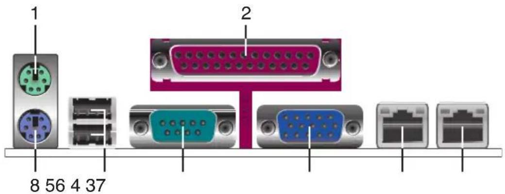
1.4 Rear panel features
The rear panel includes the power switch, expansion slot, system power socket, and power fan. The middle part includes the I/O shield with openings for the rear panel connectors on the motherboard.
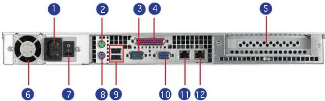
- AC power plug 7. Power switch
- PS/2 mouse port 8. PS/2 keyboard port
- Serial port 9. USB ports
- Parallel port 10. VGA port
- Expansion slot 11. LAN port1
- Power fan 12. LAN port2

The ports for the PS/2 keyboard, PS/2 mouse, USB, VGA, and Gigabit LAN do not appear on the rear panel if motherboard is not present.

Refer to section 1.6.2 Rear panel LEDs for the LED descriptions.
1.5 Internal features
The barebone server includes the basic components as shown.
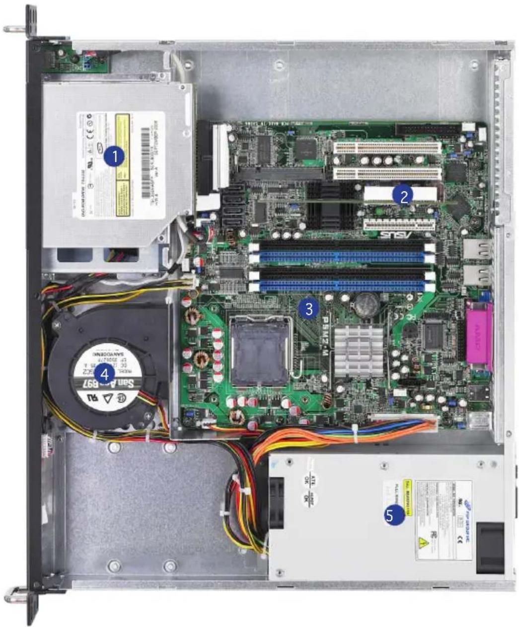
- Optical drive (optional)
- PCI-E Slot (riser card)
- ASUS P5M2-M/RS100-E4 motherboard
- System blower
- Power supply
1.6 LED information
1.6.1 Front panel LEDs
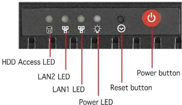
| LED Display status | Description | |
| Power button ON Press to turn system power ON | ||
| HDD Access LED OFF | Blinking | No activityRead/write data into the HDD |
| HDD Status access | ONOFF | HDD is presentNo HDD present |
| Power LED OFF | ON | System power is OFFSystem power is ON |
| Reset button ON Press to restart system | ||
| LAN LEDs OFF | BlinkingON | No LAN connectionLAN is transmitting or receiving dataLAN connection is present |
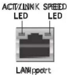
1.6.2 Rear panel LEDs
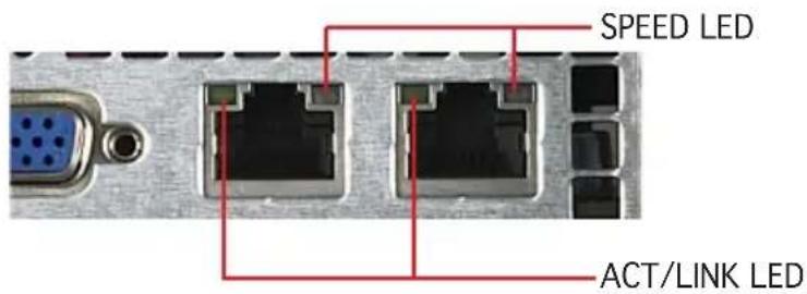
| ACT/LINK LED SPEED LED | |||
| Status Description Status Description | |||
| OFF No link OFF 10Mbps connection | |||
| Green | Linked | Orange 100Mbps connection | |
| Blinking | Linking | Green | 1000Mbps connection |
Chapter 2
This chapter lists the hardware setup procedures that you have to perform when installing or removing system components.
Hardware setup
2.1 Chassis cover
2.1.1 Removing the cover
- Use a Phillips screwdriver to remove the two screws on the top cover.
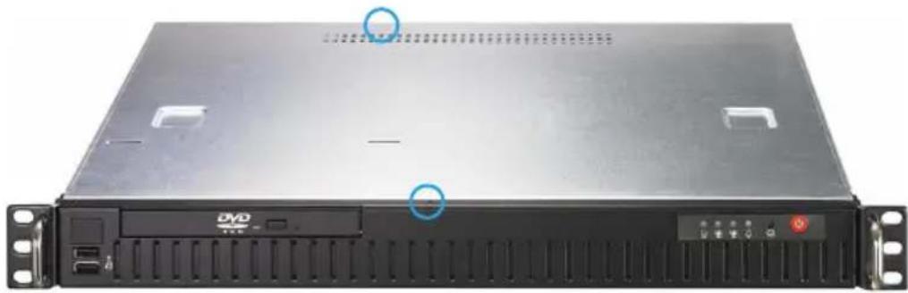
natural_image
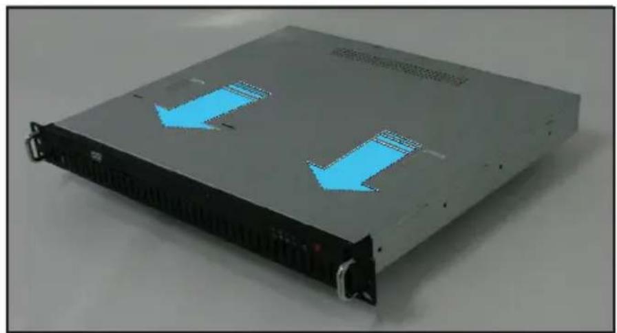
Front view of a server rack unit with ventilation slots and ports (no readable text or symbols)- Firmly hold the cover and slide it toward the rear panel for about half an inch until it is disengaged from the chassis.
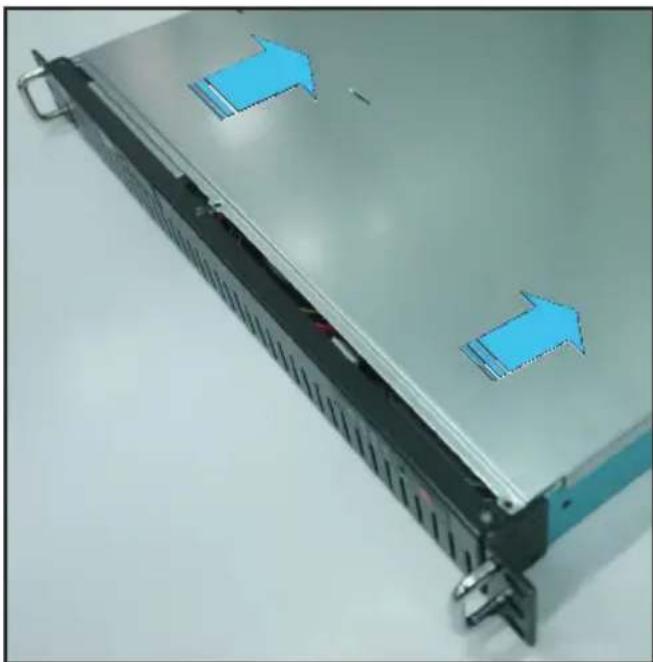
natural_image
Front view of a server rack with blue directional arrows indicating movement or flow (no text or symbols present)- Lift the cover from the chassis.
2.1.2 Installing the cover
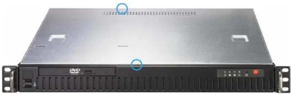
- Position the cover on top of the chassis with the hooks aligned to the side tabs of the chassis.
- Slide the cover toward the front until it snaps in place.
natural_image
Front view of a server rack with two blue directional arrows indicating data flow (no text or symbols visible)- Secure the cover with two screws.
natural_image
Front view of a server rack unit with ventilation slots and drive bays (no visible text or labels)2.2 Motherboard information
Place eight (8) screws into the holes indicated by circles to secure the motherboard to the chassis.

Refer to "Chapter 4 Motherboard Information" for detailed Information.
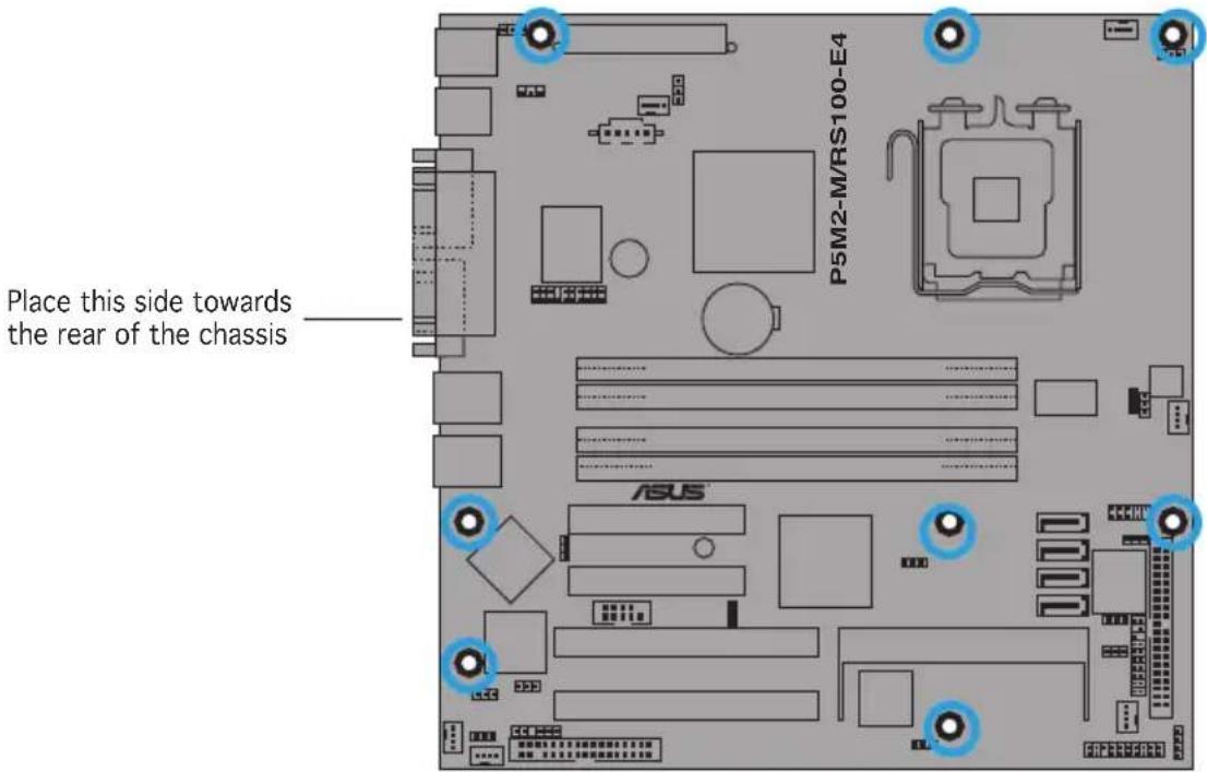

Make sure to unplug the power cord before installing or removing the motherboard. Failure to do so can cause you physical injury and damage motherboard components.
2.3 Central Processing Unit (CPU)
The motherboard comes with a surface mount LGA775 socket designed for the Intel ^® Xeon ^® 3000 series processors in the 775-land package.

- Upon purchase of the motherboard, make sure that the PnP cap is on the socket and the socket contacts are not bent. Contact your retailer immediately if the PnP cap is missing, or if you see any damage to the PnP cap/socket contacts/motherboard components. ASUS shoulders the repair cost only if the damage is shipment/transit-related.
- Keep the cap after installing the motherboard. ASUS will process Return Merchandise Authorization (RMA) requests only if the motherboard comes with the cap on the LGA775 socket.
- The product warranty does not cover damage to the socket contacts resulting from incorrect CPU installation/removal, or misplacement/loss/incorrect removal of the PnP cap.
2.3.1 Installing the CPU
To install a CPU:
- Locate the CPU socket on the motherboard.
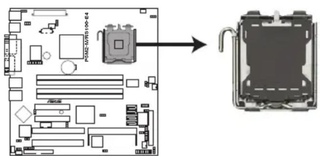
P5M2-M/RS100-E4 CPU Socket 775

Before installing the CPU, make sure that the cam box is facing towards you and the load lever is on your left.
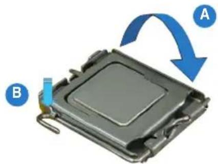
- Press the load lever with your thumb (A), then move it to the left (B) until it is released from the retention tab.
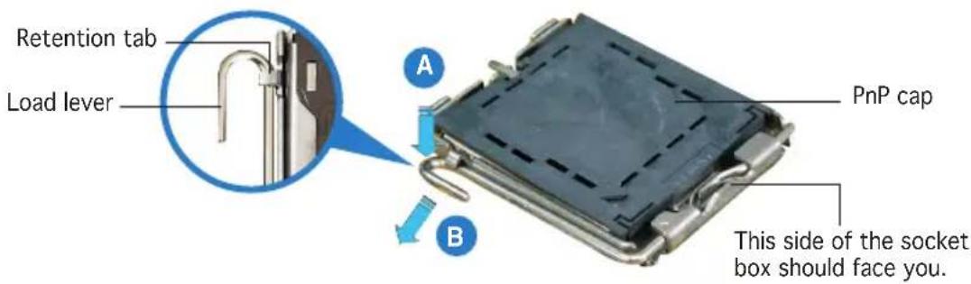

To prevent damage to the socket pins, do not remove the PnP cap unless you are installing a CPU.
- Lift the load lever in the direction of the arrow to a 135^ angle.
natural_image
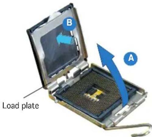
Close-up of a metallic electronic component with a blue curved arrow and metal hook (no visible text or symbols)- Lift the load plate with your thumb and forefinger to a 100^ angle (A), then push the PnP cap from the load plate window to remove (B).
- Position the CPU over the socket, making sure that the gold triangle is on the bottom-left corner of the socket. The socket alignment key should fit into the CPU notch.
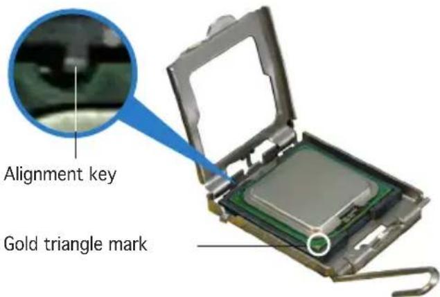

The CPU fits in only one correct orientation. DO NOT force the CPU into the socket to prevent bending the connectors on the socket and damaging the CPU!
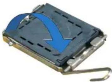
- Close the load plate (A), then push the load lever (B) until it snaps into the retention tab.
natural_image
3D rendering of a computer processor with blue arrows indicating rotation or process (no text or symbols)
The motherboard supports Intel ^® Xeon ^® 3000 series processors with the Intel ^® Enhanced Memory 64 Technology (EM64T), and Enhanced Intel SpeedStep ^® Technology (EIST). Refer to the Appendix for more information on these CPU features.
2.3.2 Installing the CPU heatsink
The Intel ^® Xeon ^® 3000 series processors require a specially designed heatsink and fan-duct to ensure optimum thermal condition and performance.

Use only qualified CPU heatsink assembly.
To install the CPU heatsink:
- Place the heatsink on top of the installed CPU, matching the screw holes with the heatsink standoffs.

Make sure that the heatsink grill is parallel to the nozzle of the system blower as shown.
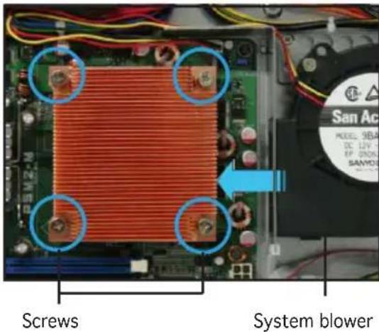
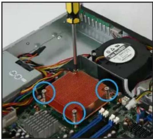
- Tighten the screws.
natural_image
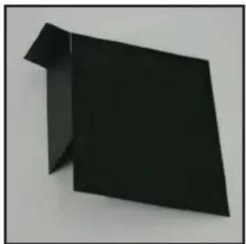
Close-up of a computer motherboard with visible CPU socket, screwdriver, and wiring (no text or symbols)- Peel the adhesive cover of the heatsink plastic cover and evenly attach to heatsink.
natural_image
Abstract black geometric shape on white background (no text or symbols)Heatsink plastic cover
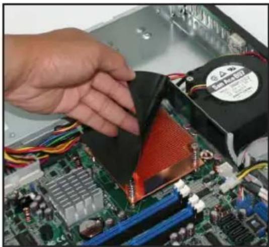
natural_image
Close-up of hands installing a computer motherboard with visible CPU socket and heatsink (no text or symbols)The heatsink plastic cover ensures the linear airflow between the heatsink and system blower.
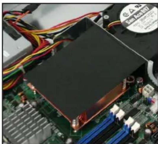
natural_image
Close-up of a computer motherboard with visible CPU socket and wiring (no readable text or symbols)2.4 System memory
2.4.1 Overview
The motherboard comes with four Double Data Rate 2 (DDR2) Dual Inline Memory Modules (DIMM) sockets.
A DDR2 module has the same physical dimensions as a DDR DIMM but has a 240-pin footprint compared to the 184-pin DDR DIMM. DDR2 DIMMs are notched differently to prevent installation on a DDR DIMM socket.
The figure illustrates the location of the DDR2 DIMM sockets:
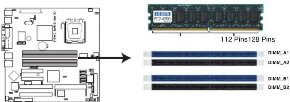
P5M2-M/RS100-E4 240-pin DDR2 DIMM Sockets
2.4.2 Memory configurations
You may install 512 MB, 1 GB, and 2 GB unbuffered ECC or non-ECC DDR2-533/667 DIMMs into the DIMM sockets.

- Always install DIMMs with the same CAS latency. For optimum compatibility, we recommend that you obtain memory modules from the same vendor. Refer to the DDR2 Qualified Vendors List on the ASUS web site.
- When installing one or two DIMMs, install the DIMM(s) to the blue slots (DIMM_A1/DIMM_B1).
- Three DDR2 DIMMs intalled into any three memory sockets will function in single-channel mode.
2.4.3 Installing a DIMM

Unplug the power supply before adding or removing DIMMs or other system components. Failure to do so can cause severe damage to both the motherboard and the components.
To install a DIMM:
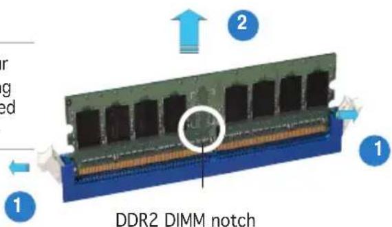
- Unlock a DIMM socket by pressing the retaining clips outward.
- Align a DIMM on the socket such that the notch on the DIMM matches the break on the socket.
- Firmly insert the DIMM into the socket until the retaining clips snap back in place and the DIMM is properly seated.
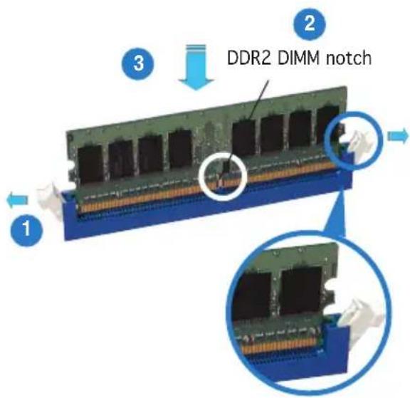
Unlocked retaining clip

- A DDR2 DIMM is keyed with a notch so that it fits in only one direction. DO NOT force a DIMM into a socket to avoid damaging the DIMM.
- The DDR2 DIMM sockets do not support DDR DIMMs. DO NOT install DDR DIMMs to the DDR2 DIMM sockets.
2.4.4 Removing a DIMM
Follow these steps to remove a DIMM.
- Simultaneously press the retaining clips outward to unlock the DIMM.

Support the DIMM lightly with your fingers when pressing the retaining clips. The DIMM might get damaged when it flips out with extra force.
- Remove the DIMM from the socket.
2.5 Replaceable components
You may need to replace defective components or remove previously installed system components when installing or removing system devices. This section tells how to install or remove the following components:
- System blower
- Serial ATA hard disk drive
- Optical disk drive
2.5.1 Installing the system blower
To install the system blower:
- Locate the system blower plate on the chassis.
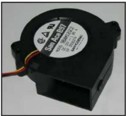
System blower
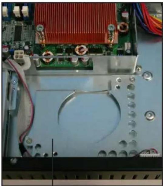
natural_image
Close-up of an electronic device's internal components, including a CPU socket and motherboard with visible wiring (no text or symbols)System blower plate
- Align the nozzle of the system blower towards the heatsink.
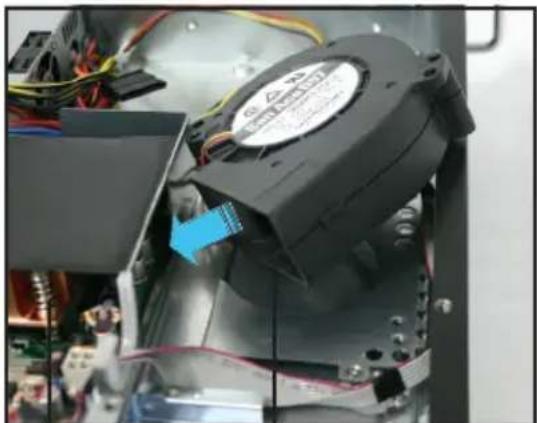
natural_image
Close-up of an electronic device with a black motor and wiring, showing internal components (no visible text or symbols)Heatsink
System blower nozzle
- Secure the system blower with two screws.
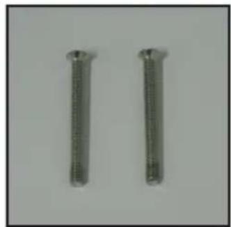
natural_image
Two metallic cylindrical pins with threaded ends, isolated on a plain background (no text or symbols)System blower screws
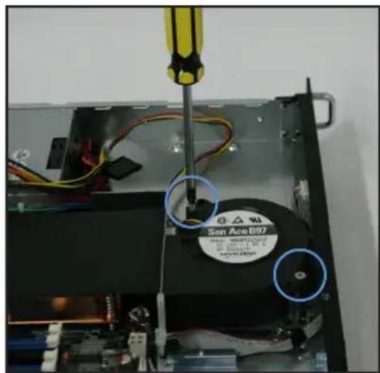
- Connect the system blower cable to the onboard fan connector labeled CPU_FAN1. Refer to the illustration below for the location of CPU_FAN1 connector.
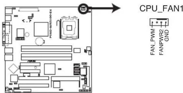
P5M2-M/RS100-E4 CPU Fan connector
2.5.2 Installing Serial ATA drives
You can install up to two (2) Serial ATA hard disk drives to the system. Follow the succeeding instructions to install each of the drives.
To install primary Serial ATA drive:
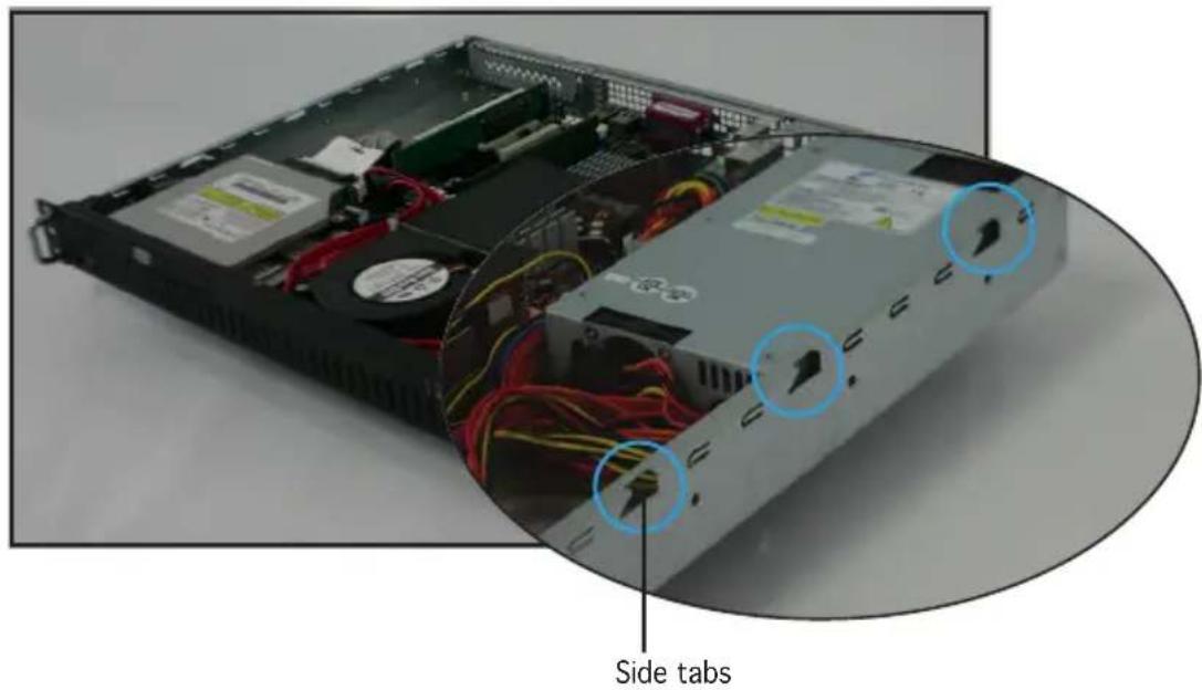
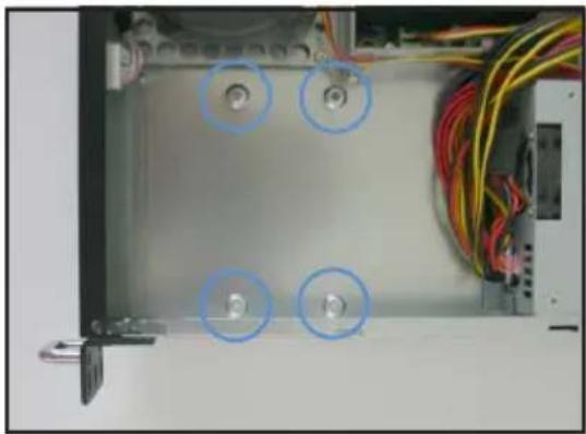
- Locate the Serial ATA drive bay beside the power supply unit. Notice the four standard screw holes.
natural_image
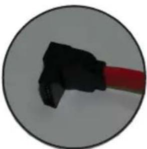
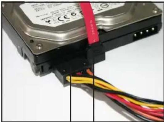
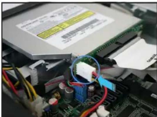
Interior view of an electronic equipment enclosure showing wiring and a central panel with four circular annotations (no text or symbols visible)- Connect the Serial ATA signal cable and ATX power connectors. Use the L-type Serial ATA connector to connect to the hard drive.
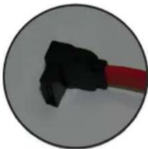
natural_image
Close-up of a black mechanical component with a red rod, enclosed in a circular frame (no text or symbols visible)SATA L-type connector
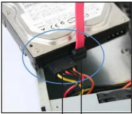
natural_image
Close-up of a hard disk drive with visible internal wiring and a red cable inserted (no text or symbols)ATX power connector
SATA signal cable
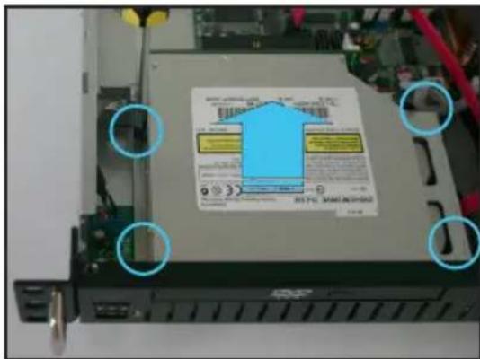
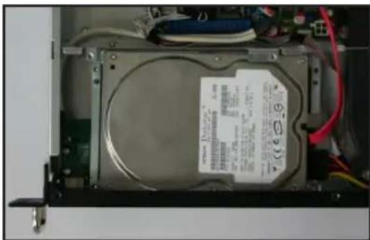
- Place the Serial ATA drive into the drive bay matching the four screw holes with the holes on the disk drive.
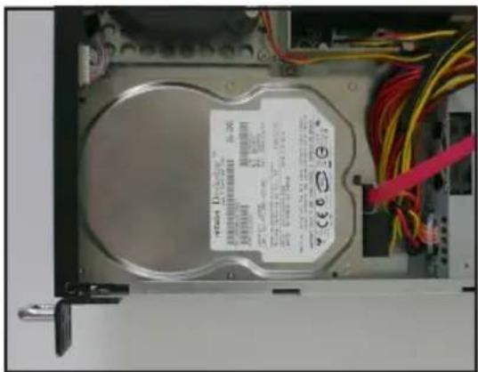
natural_image
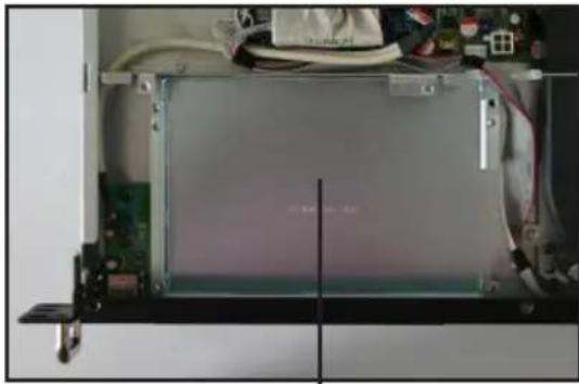
Internal view of a computer drive bay with visible internal components and wiring (no readable text or symbols)- Secure the hard drive with four screws.
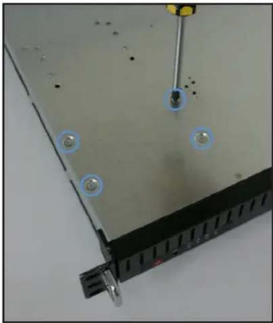
natural_image
Close-up of a computer monitor with screwdriver and two circular components, no visible text or symbols- Connect the other end of the Serial ATA signal connector to the onboard SATA connector labeled SATA1. Refer to illustration below for the location of SATA1 connector.
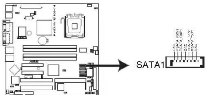
P5M2-M/RS100-E4 SATA1 connector
To install secondary Serial ATA drive:
- If you have an ODD installed, remove the ODD bay first before you install a secondary SATA disk drive.
To remove, disconnect the ODD cable and power cable then use a screwdriver to remove all four screws.
- Locate the Serial ATA drive plate under the optical disk drive (ODD) bay.
natural_image
Interior view of an electronic device with visible circuit board and wiring (no readable text or symbols)SATA drive plate
- Connect the Serial ATA signal cable and ATX power connectors. Use the L-type Serial ATA connector to connect to the hard drive.
natural_image
Close-up of a black USB flash drive with red cable, enclosed in a circular frame (no text or symbols visible)SATA L-type connector
natural_image
Close-up of a hard disk drive with visible wiring and cable (no text or symbols)ATX power connector
SATA signal cable
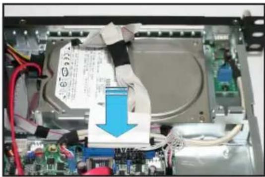
- Insert the Serial ATA drive into the drive plate as shown.
natural_image
Interior view of an electronic device showing a CD drive casing with visible circuitry and wiring (no readable text or symbols)Chapter 2: Hardware setup2-16
- Connect the other end of the Serial ATA signal connector to the onboard SATA connector labeled SATA3.
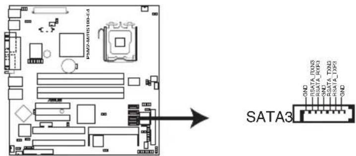
P5M2-M/RS100-E4 SATA3 connector
2.5.3 Installing optical disk drive (ODD)
To install ODD:
- Connect the 80-pin IDE cable blue connector to the IDE connector onboard.
natural_image
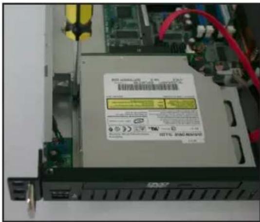
Interior view of an electronic device showing a cable with a blue arrow pointing to a component, no visible text or symbols.- Align the bundled optical disk drive* (ODD) into the drive slot as shown.
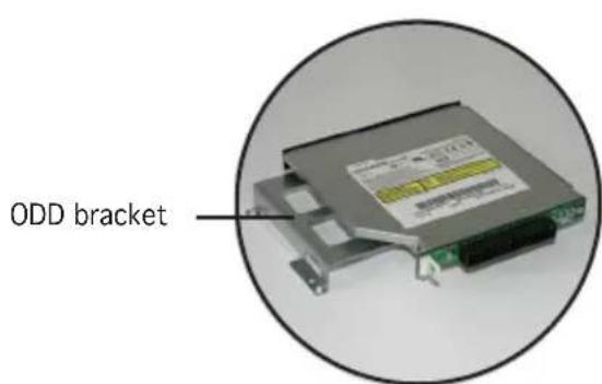
Optical disk drive (*optional)
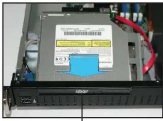
Optical disk drive slot
- Align the screw holes of the ODD bracket with the screw holes on the SATA drive plate then secure with four screws.
- Connect the 80-pin IDE cable black connector to the IDE connector at the rear of the optical disk drive.
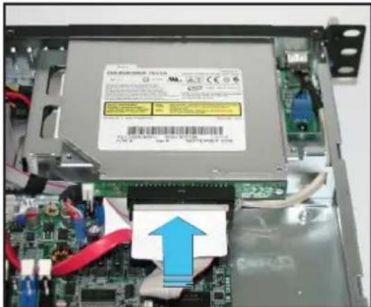
natural_image
Interior view of an electronic device showing a circuit board with a highlighted component and a blue upward arrow (no readable text or symbols)- Connect a 4-pin ATX power connector to the power connector at the rear of the optical disk drive.
natural_image
Close-up of a computer motherboard with visible CPU socket and wiring, no readable text or symbols present.Chapter 3
This chapter describes how to install the optional components and devices into the barebone server.
installation options
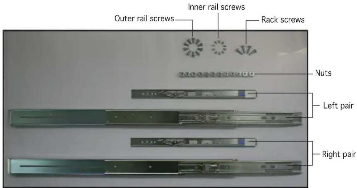
3.1 Rackmount rail kit items
The rackmount rail kit contains two pairs of rails (one pair for each side of the server system), twelve (12) pieces of rail nuts, ten (10) pieces of inner rail screws, ten (10) pieces of outer rail screws, and four (4) pieces of rack screws.
3.2 Attaching the rack ears
The bundled rack ears serve as handle when inserting or pulling the server from a rack cabinet.
To attach rack ears:
- Prepare the bundled pair of rack ears and set of eight (8) screws.
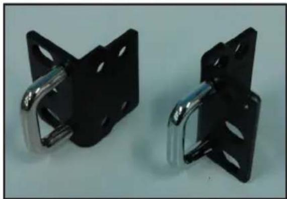
natural_image
Two black metal bracket clips with metallic clips, shown against a plain background (no text or symbols visible)Pair of rack ears
- Locate the four screw holes on each front-side of the chassis. Select one side for installation.
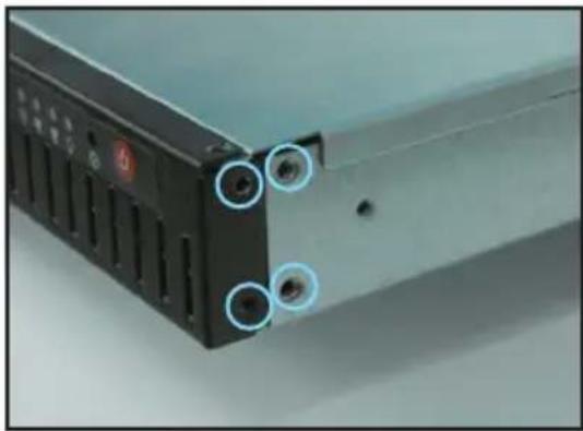
natural_image
Close-up of a computer drive with three circular annotations pointing to ports (no visible text or symbols)-
Get one rack ear and match the four screw holes to the screw holes on the chassis. Orient the rack ear as shown.
-
Secure the rack ear to the chassis with four screws.
-
Repeat steps 2 - 4 to attach the other rack ear.
natural_image
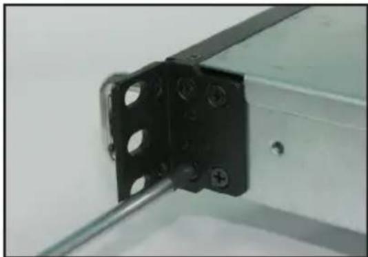
Close-up of a black metal bracket with mounting holes and a metal rod inserted (no text or symbols visible)3.3 Attaching the rails to the rack
To attach the rack rails:
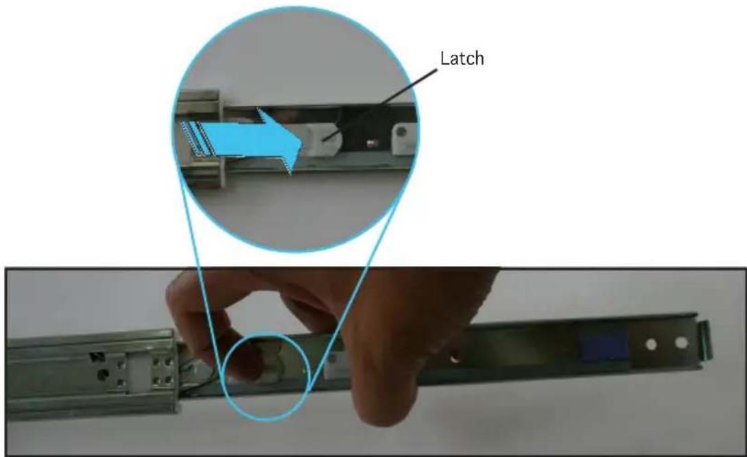
- Release the inner rail on each rail set, by sliding the latch to direction as indicated by arrow. When released, pull out the inner rail.
- Attach the inner rail to the corresponding side of the chassis and secure with three inner rail screws. Make sure the rail is oriented as shown.
natural_image
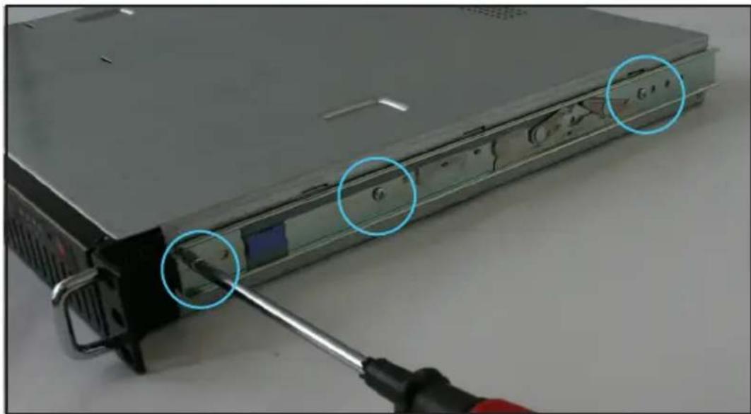
Close-up of a server rack with a screwdriver inserted, showing internal components and a highlighted cable (no text or symbols visible)-
Attach the second inner rail to the other side of the chassis and secure with three inner rail screws.
-
Select one unit of space (1U) on the rack where you wish to install the server.
-
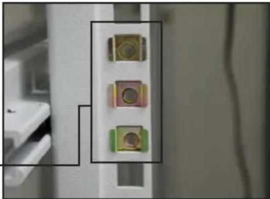
Place three (3) nuts on the front and three at the back. Do the same to the corresponding side of the rack.
-
Adjust the length of the outer rail to fit the length of the rack cabinet then fasten the two screws.
natural_image
Close-up of three electronic components mounted on a vertical pole, with no visible text or symbols.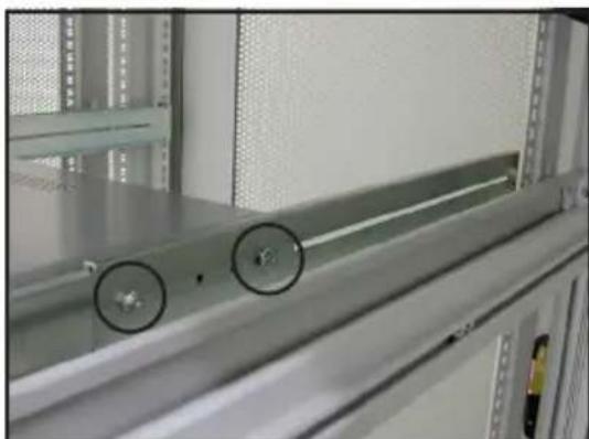
natural_image
Interior view of a server rack with metal shelves and a cylindrical component, showing two circular features (no text or symbols visible)-
Secure the outer rail with two screws at the front and rear of the rack cabinet.
-
Find the corresponding 1U space on the other side of the rack cabinet then repeat steps 6 and 7 to attach the other outer rail.
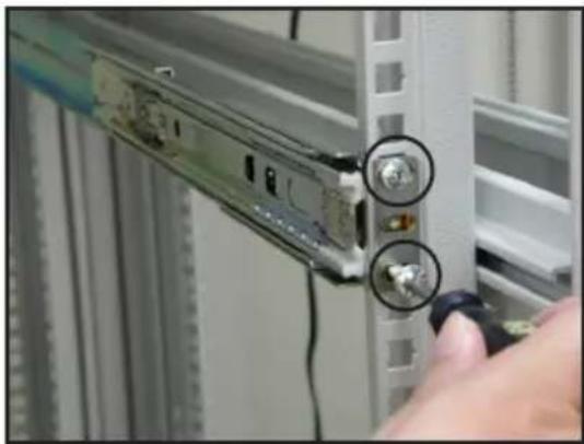
natural_image
Close-up of a hand inserting a cable into a server rack, showing two inserted connectors (no text or symbols visible)- Using the rack ears, firmly hold the server on both sides and insert the rear panel side to the front end of the rack rail.
Make sure that the inner rails are properly aligned with the outer rails.
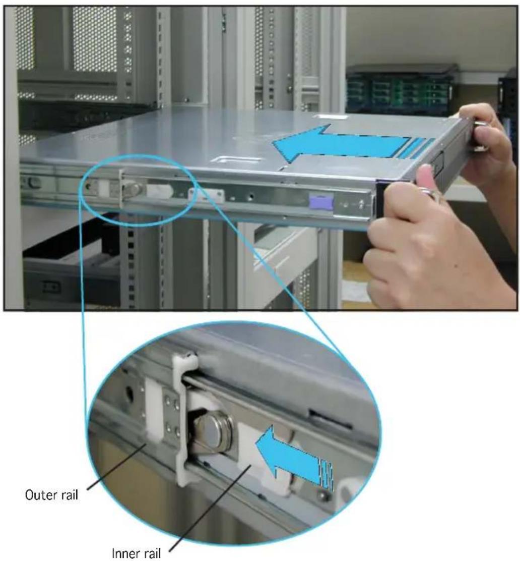
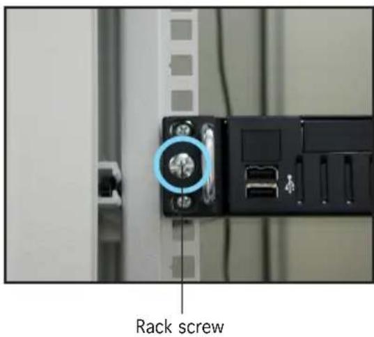
- Carefully push the server all the way to the back until the front panel fits the front end of the rack, and the rack screw holes on the server match the middle hole on the rack.
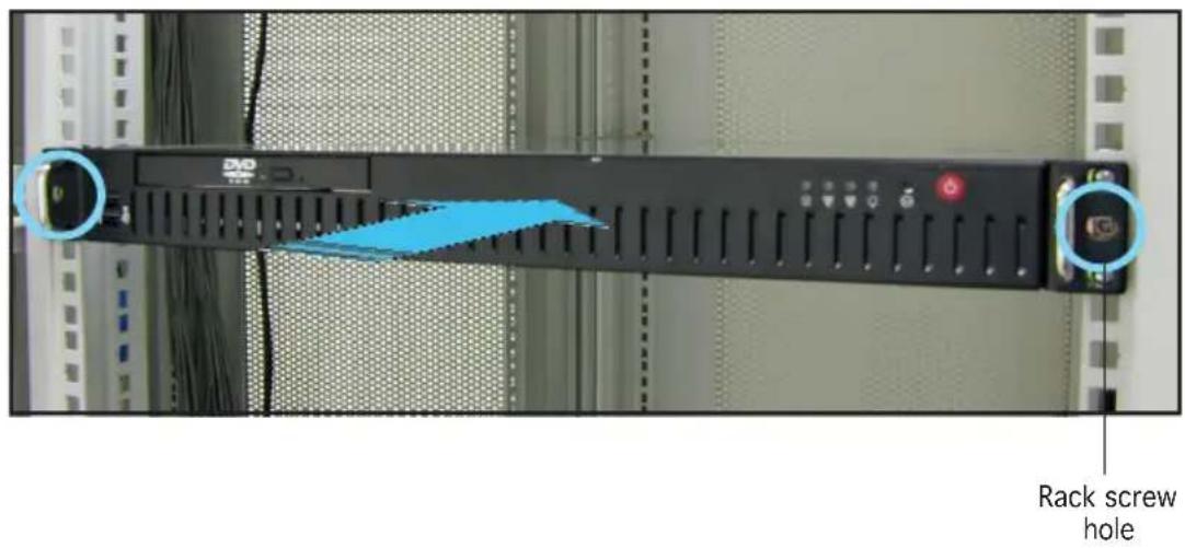
- Secure the server to the rack with two rack screws.
Chapter 4
This chapter gives information about the motherboard that comes with the server. This chapter includes the motherboard layout, jumper settings, and connector
Mothereboar info
4.1 Motherboard overview
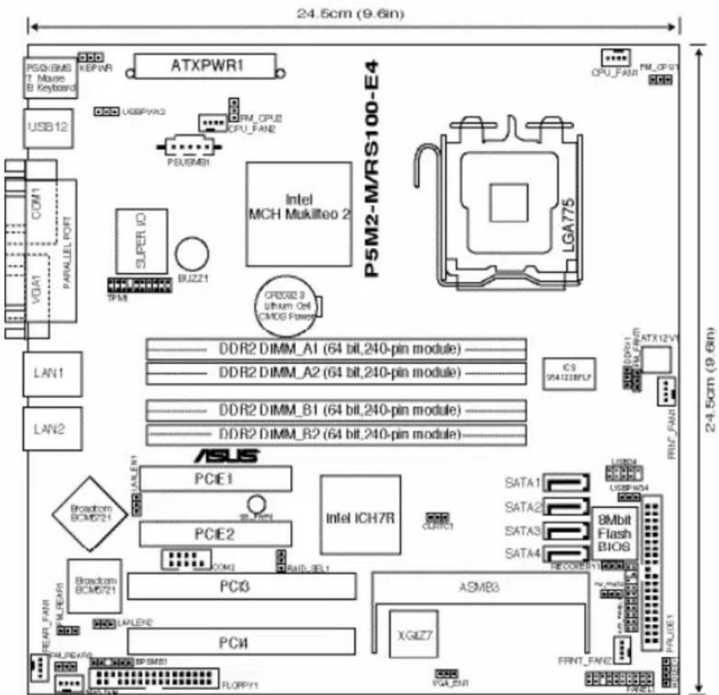
Layoutcontents
| Slots/Socket Page | Page |
| 1. CPU socket 2-6 | |
| 2. DDR2 DIMM slots 2-13 | |
| 3. PCI/PCI Express slots | 2-17 |
| Jumpers | Page |
| 1. Clear RTC RAM (CLRTC1) | 2-18 |
| 2. CPU fan pin selection (3-pin FM_CPU1, FM_CPU2) | 2-19 |
| 3. USB device wake-up (3-pin USBPW12, USBPW34) | 2-19 |
| 4. Keyboard/Mouse power (3-pin KBPWR1) | 2-20 |
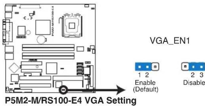
| 5. VGA controller setting (3-pin VGA_EN1) | 2-20 |
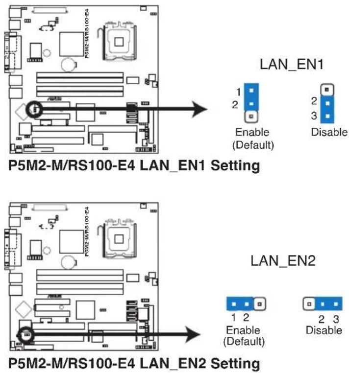
| 6. Gigabit LAN controller setting (3-pin LAN_EN1; LAN_EN2) | 2-21 |
| 7. RAID controller selection (3-pin RAID_SEL1) | 2-21 |
| 8. Force BIOS recovery setting (3-pin RECOVERY1) | 2-22 |
| Rearrpaa@Iconee@coss Page Page | |
| 1. PS/2 mouse port (green) 2-23 | |
| 2. Parallel port 2-23 | |
| 3. Gigabit LAN1 (RJ-45) port 2-23 | |
| 4. Gigabit LAN2 (RJ-45) port 2-23 | |
| 5. VGA port 2-23 | |
| 6. Serial (COM1) port 2-23 | |
| 7. USB 2.0 ports 1 and 2 2-23 | |
| 8. PS/2 keyboard port (purple) 2-23 | |
| Internal connectors of Page | Page |
| 1. Floppy disk drive connector (34-1 pin FLOPPY1) 2-24 | |
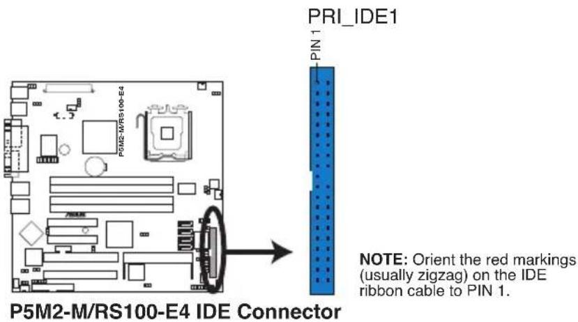
| 2. ICH7R primary IDE connectors (40-1 pin PRI_IDE1) 2-25 | |
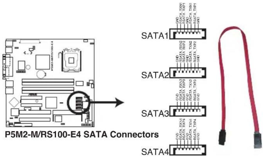
| 3. Serial ATA connectors (7-pin SATA1, SATA2, SATA3, SATA4) 2-26 | |
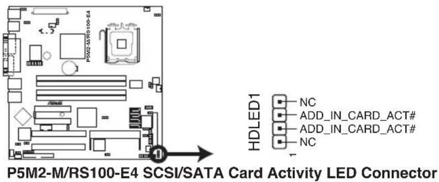
| 4. Hard disk activity LED connector (4-pin HDLED1) 2-27 | |
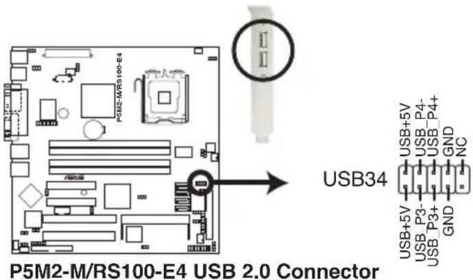
| 5. USB connector (10-1 pin USB34) 2-27 | |
| 6. Serial port connector (10-1 pin COM2) 2-28 | |
| 7. CPU and system fan connectors (3-pin CPU_FAN1/2, 2-28 REAR_FAN1/2, FRNT_FAN1/2) | |
| 8. Backplane SMBus connector (6-1 pin BPSMB1) 2-29 | |
| 9. Power supply SMBus connector (5-pin PSUSMB1) 2-29 | |
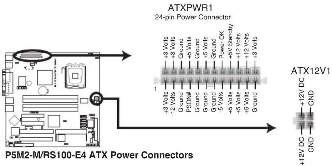
| 10. SSI power connectors (24-pin ATXPWR1, 8-pin ATX12V2) | 2-30 |
| 11. Auxiliary panel connector (20-pin AUX_PANEL1) | 2-31 |
| 12. System panel connector (20-pin PANEL1) | 2-32 |
4.2 Jumpers
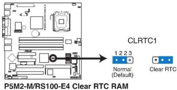
1. Clear RTCRAM(CLRTC1)TC1)
This jumper allows you to clear the Real Time Clock (RTC) RAM in CMOS. You can clear the CMOS memory of date, time, and system setup parameters by erasing the CMOS RTC RAM data. The onboard button cell battery powers the RAM data in CMOS, which include system setup information such as system passwords.
To erase the RTC RAM:
- Turn OFF the computer and unplug the power cord.
- Remove the onboard battery.
- Move the jumper cap from pins 1-2 (default) to pins 2-3. Keep the cap on pins 2-3 for about 5\~10 seconds, then move the cap back to pins 1-2.
- Re-install the battery.
- Plug the power cord and turn ON the computer.
- Hold down the
key during the boot process and enter BIOS setup to re-enter data.

Except when clearing the RTC RAM, never remove the cap on CLRTC jumper default position. Removing the cap will cause system boot failure!
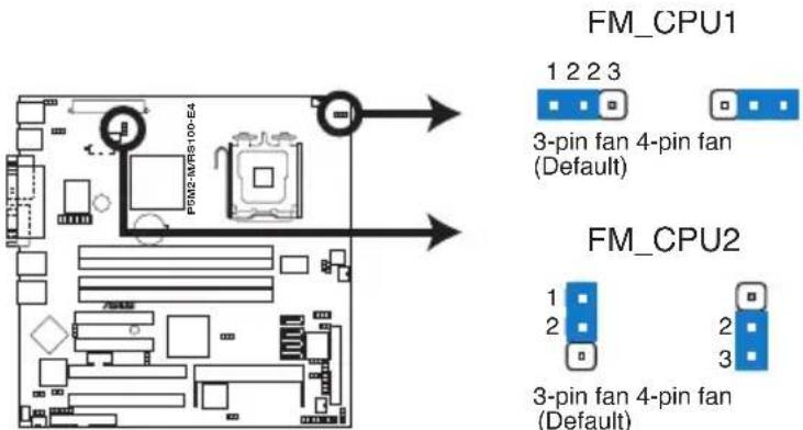
2. CRUP fan pin selection (6-pin FM\_pCPUAMEPCPU2FM\_CPU2)
These jumpers allow you to connect either a 3-pin or a 4-pin fan cable plug to the CPU fan connectors (CPU_FAN1, CPU_FAN2). Set these jumpers to pins 1-2 if you are using a 3-pin fan cable plug, or to pins 2-3 if you are using a 4-pin plug.
Set these jumpers to +5V to wake up the computer from S1 sleep mode (CPU stopped, DRAM refreshed, system running in low power mode) using the connected USB devices. Set to +5VSB to wake up from S4 sleep mode (no power to CPU, DRAM in slow refresh, power supply in reduced power mode).
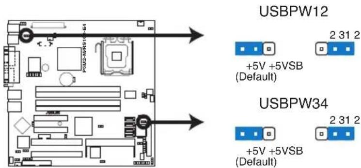
P5M2-M/RS100-E4 USB Device Wake-Up

- The USB device wake-up feature requires a power supply that can provide 500mA on the +5VSB lead for each USB port; otherwise, the system would not power up.
- If you are using Windows 2000, you need to install Service Pack 4 to wake up the system from S4 sleep mode.
- The total current consumed must NOT exceed the power supply capability (+5VSB) whether under normal condition or in sleep mode.
4. Keyboard/Mouse power (3-pin(KBPWR1)BPWR1)
This jumper allows you to enable or disable the keyboard/mouse wake-up feature. Set this jumper to pins 2-3 (+5VSB) to wake up the computer when you press a key on the keyboard (the default is the Space Bar) or use the mouse. This feature requires an ATX power supply that can supply at least 1A on the +5VSB lead, and a corresponding setting in the BIOS.
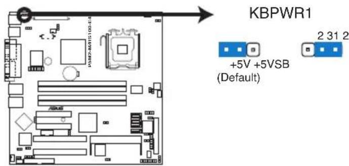
P5M2-M/RS100-E4 Keyboard Power Setting
5. VGA controller setting (8-pin VGA\_iEN1GA\_EN1)
These jumpers allow you to enable or disable the onboard XGI Volari Z7® PCI VGA controller. Set to pins 1-2 to activate the VGA feature.
6. GigabitLAN\_controllersetting [3-pimgLAN-EN1LLAN\_EN2) LAN\_EN2)
These jumpers allow you to enable or disable the onboard Broadcom® BCM5721 Gigabit LAN1 or LAN2 controller. Set to pins 1-2 to activate the Gigabit LAN controller.
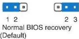
7. RAIDController selection(3-ipin RAIDjSERAD\_SEL1)
This jumper allows you to select the RAID configuration utility to use when you create disk arrays. Place the jumper caps over pins 1-2 if you want to use the LSI Logic Embedded SATA RAID Setup Utility (default); otherwise, place the jumper caps to pins 2-3 to use the Intel® Matrix Storage Manager.
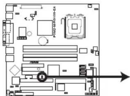
RAID_SEL1
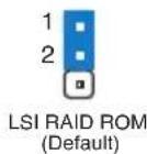
P5M2-M/RS100-E4 RAID_SEL1 Setting
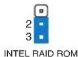
8. Force BIOS recovery setting (Step RECOVERY RECOVERY1)
This jumper allows you to quickly update or recover the BIOS when it gets corrupted.
To update the BIOS:
- Prepare a floppy disk that contains the latest BIOS for the motherboard (xxxx-xxx.ROM) and the AFUDOS.EXE utility.
- Set the jumper to pins 2-3.
- Insert the floppy disk then turn on the system to update the BIOS.
- Shut down the system.
- Set the jumper back to pins 1-2.
- Turn on the system.

RECOVERY1
P5M2-M/RS100-E4 BIOS Recovery Setting
4.3 Connectors
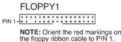
4.3.11 Rear panel connectors
- PS/2 mouse port (green). This port is for a PS/2 mouse.
- Parallel port. This 25-pin port connects a parallel printer, a scanner, or other devices.
- Gigabit LAN (RJ-4-5) port This ports allow Gigabit connection to a Local Area Network (LAN) through a network hub. Refer to the table below for the LAN port LED indications.
- Gigabit LAN2 (RJ-4-5) port This ports allow Gigabit connection to a Local Area Network (LAN) through a network hub. Refer to the table below for the LAN port LED indications.
- VGA port. This port is for a VGA monitor or other VGA-compatible devices.
- Serial(COM) port This 9-pin communication port is for pointing devices or other serial devices.
- USB 2.0 ports and 2. These two 4-pin Universal Serial Bus (USB) ports are available for connecting USB 2.0 devices.
- PS/2 keyboard port (purple). This port is for a PS/2 keyboard.
LAN port LHD indications
| ACT/LINK KEDED SPEED LED | SPEED LED | ||
| Status Description Status | Status Description | ||
| OFF | No link | OFF | 10 Mbps connection |
| GREEN | Linked | ORANGE | 100 Mbps connection |
| BLINKING | Data activity | GREEN | 1 Gbps connection |
4.3.22 Internal connectors
1. FI6bpydjskdrivelconnection(34-drp(nFLOPPY1)FLOPPY1)
This connector is for the provided Floppy Disk Drive (FDD) signal cable. Insert one end of the cable to this connector, then connect the other end to the signal connector at the back of the floppy disk drive.

Pin 5 on the connector is removed to prevent incorrect cable connection when using a FDD cable with a covered Pin 5.
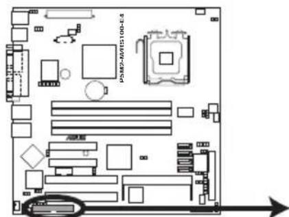
P5M2-M/RS100-E4 Floppy Disk Drive Connector
2. ICH7R primary IDE do Electron(40-1rp(nPRILIDE1)PRI\_IDE1)
This connector is for an Ultra DMA 100/66 signal cable. The Ultra DMA 100/66 signal cable has three connectors: a blue connector for the primary IDE connector on the motherboard, a black connector for an Ultra DMA 100/66 IDE slave device (optical drive/hard disk drive), and a gray connector for an Ultra DMA 100/66 IDE master device (hard disk drive). If you install two hard disk drives, you must configure the second drive as a slave device by setting its jumper accordingly. Refer to the hard disk documentation for the jumper settings.

- Pin 20 on the IDE connector is removed to match the covered hole on the Ultra DMA cable connector. This prevents incorrect insertion when you connect the IDE cable.
- Use the 80-conductor IDE cable for Ultra DMA 100/66 IDE devices.
3. SerialATA Connectors(7-pin (SATA1, SATA2,, SATA3,2, SATA3, SATA4))
These connectors are for the Serial ATA signal cables for Serial ATA hard disk drives.
If you installed Serial ATA hard disk drives, you can create a RAID 0 and RAID 1 configuration using the Intel® Matrix Storage Technology or the LSI MegaRAID® utility embedded in the Intel® ICH7R Southbridge.

These connectors are setIDE mode by default. InIDE mode, you can connect Serial ATA boot/data hard disk drives to these connectors. If you intend to create a Serial ATA RAID set using these connectors, set the Configure SATA as item in the BIOS to [RAID]. See section "4.3.4 IDE Configuration" for details.

Important notes on Serial ATA
- Use only two Serial ATA RAID connectors for each RAID 0 or RAID 1 set.
- When using the connectors in IDE mode, connect the primary (boot) hard disk drive to the SATA1 or SATA2 connector. Refer to the table below for the recommended SATA hard disk drive connections.
Serial AAT A hard disk drive connection
| Connector Setting Using | Use | |
| SATA3A5ATA2ATMaster | Boot disk | Boot disk |
| SATA3A5ATA3ATSave | Data disk | Data disk |
4. Hard disk activity of LED chellectron (4-pin HDLED1r) HDLED1
This connector supplies power to the hard disk activity LED. The read or write activities of any device connected to the SCSI connectors or the SATA connectors cause this LED to light up.
This connector is for USB 2.0 ports. This USB connector complies with USB 2.0 specification that supports up to 480 Mbps connection speed.
6. Serial port connector(10-1 pinCOM2) COM2)
This connector is for a serial (COM) port. Connect the serial port module cable to this connector, then install the module to a slot opening at the back of the system chassis. The serial port module is purchased separately.
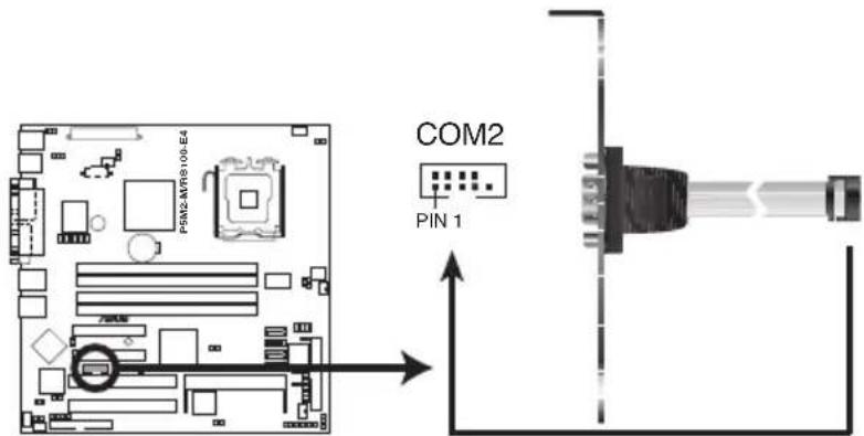
P5M2-M/RS100-E4 Serial Port2 (COM2) Connector
7. CPU and system fan connectors sectors
(3-pinCPULFAN1,NCPUCFAN2)
The fan connectors support cooling fans of 350 mA \~ 740 mA (8.88 W max.) or a total of 2.1 A \~ 4.44 A (53.28 W max.) at +12V.
Connect the fan cables to the fan connectors on the motherboard, making sure that the black wire of each cable matches the ground pin of the connector.

Do not forget to connect the fan cables to the fan connectors.
Insufficient air flow inside the system may damage the motherboard components. These are not jumpers! Do not place jumper caps on the fan connectors!
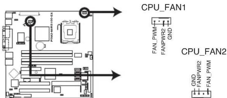
P5M2-M/RS100-E4 CPU Fan connectors
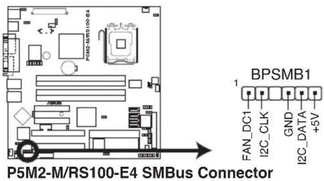
8. Backplane SMBus Connection (6-10 pin BPSMB1)BPSMB1
This connector allows you to connect SMBus (System Management Bus) devices. Devices communicate with an SMBus host and/or other SMBus devices using the SMBus interface.
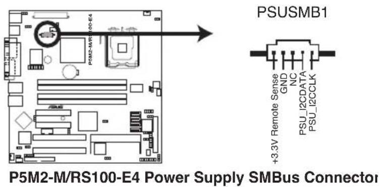
9. Power supply SMBus connector(5-pin PSUSMB1)PSUSMB1)
This connector is for the power supply SMB cable, if your power supply supports the SMBus function.
10. SSIppwereconnectors (24-pin ATXPWRX, 8-pin ATX1i2V2TX12V2)
These connectors are for SSI power supply plugs. The power supply plugs are designed to fit these connectors in only one orientation. Find the proper orientation and push down firmly until the connectors completely fit.

- Use of an SSI 12 V Specification 2.0-compliant power supply unit (PSU) that provides a minimum power of 450 W is recommended for a fully-configured system.
- By default, four ATX12V2 connector pins are covered to prevent incorrent insertion of a 4-pin ATX +12V power plug. Remove this cover when using a PSU with an 8-pin ATX +12V power plug.
- Do not forget to connect the 4-pin or 8-pin ATX +12 V power plug; otherwise, the system will not boot up.
- We recommend that you use a PSU with a higher power output when configuring a system with more power consuming devices. The system may become unstable or may not boot up if the power is inadequate.
- You must install a PSU with a higher power rating if you intend to install additional devices.
11. Auxiliary papelconnectoe (20-pin2AUXiPANE1 PANEL1)
This connector is for additional front panel features including front panel SMB, locator LED and switch, chassis intrusion, and LAN LEDs.
• Front panel SMB (6-6-pin FPSMB)B
These leads connect the front panel SMBus cable.
• LAINActivityEDE(2-(pH LAIN1LED,D,AN2LED)
These leads are for Gigabit LAN activity LEDs on the front panel.
- Chassis intrusion (2-pip CHASSIS)
These leads are for the intrusion detection feature for chassis with intrusion sensor or microswitch. When you remove any chassis component, the sensor triggers and sends a high-level signal to these leads to record a chassis intrusion event.
- Locator LEDE(6-pip LOCATOR)R
These leads are for the locator switch and LED on the front panel.
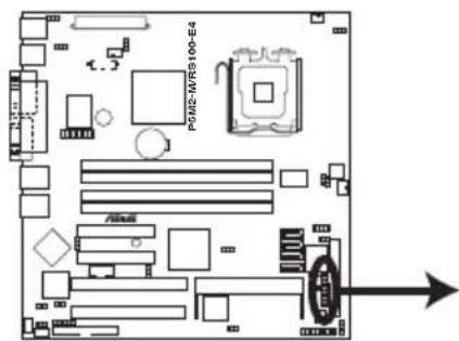
AUX_PANEL1
P5M2-M/RS100-E4 Auxiliary Panel Connector
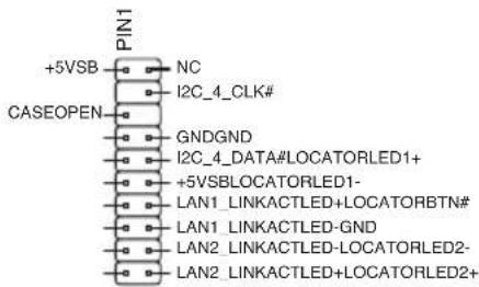
12. Systempanel connector(20-pin PANEL PANEL 1)
This connector supports several chassis-mounted functions.
• System power LEDE(Greene3-pin PLEDED)
This 3-pin connector is for the system power LED. Connect the chassis power LED cable to this connector. The system power LED lights up when you turn on the system power, and blinks when the system is in sleep mode.
- MessagingEDE(Brown2-pimMLDED)
This connector is for the message LED cable that connects to the front message LED. The message LED indicates the booting status. The LED blinks when the system is in the boot process until the operating system is loaded.
- Hard disk drive activity LEDE(Rde2-pimIDDELED)
This 2-pin connector is for the HDD Activity LED. Connect the HDD Activity LED cable to this connector. The IDE LED lights up or flashes when data is read from or written to the HDD.
- System warning speaker (Orange 4-pin SPEAKER)
This 4-pin connector is for the chassis-mounted system warning speaker. The speaker allows you to hear system beeps and warnings.
- A TXTpower button/soft-off button(Light Greene2-pip PWRSW)
This connector is for the system power button. Pressing the power button turns the system on or puts the system in sleep or soft-off mode depending on the BIOS settings. Pressing the power switch for more than four seconds while the system is ON turns the system OFF.
- Reset button (Blue 2-pin RESET)
This 2-pin connector is for the chassis-mounted reset button for system reboot without turning off the system power.

The system panel connector is color-coded for easy connection.
Chapter 5
This chapter tells how to change the system settings through the BIOS Setup menus. Detailed descriptions of the BIOS parameters are also provided.
BIOS setup
5.1 Managing and updating your BIOS
The following utilities allow you to manage and update the motherboard Basic Input/Output System (BIOS) setup.
- ASUS AFUDOS (Updates the BIOS in DOS mode using a bootable floppy disk.)
- ASUS CrashFree BIOS 2 (Updates the BIOS using a bootable floppy disk or the motherboard support CD when the BIOS file fails or gets corrupted.)
- ASUS Update (Updates the BIOS in Windows ^ environment.)
Refer to the corresponding sections for details on these utilities.

Save a copy of the original motherboard BIOS file to a bootable floppy disk in case you need to restore the BIOS in the future. Copy the original motherboard BIOS using the ASUS Update or AFUDOS utilities.
5.1.11 Creating a bootable floppy disk py disk
To create a bootable floppy disk in a DOS environment:
a. Insert a 1.44MB floppy disk into the drive.
b. At the DOS prompt, type format A:/S then press
5.1.22 AFUPOSutility
The AFUDOS utility allows you to update the BIOS file in DOS environment using a bootable floppy disk with the updated BIOS file. This utility also allows you to copy the current BIOS file that you can use as backup when the BIOS fails or gets corrupted during the updating process.
Copying the current BIOSIOS
To copy the current BIOS file using the AFUDOS utility:

- Make sure that the floppy disk is not write-protected and has at least 1024 KB free space to save the file.
-
The succeeding BIOS screens are for reference only. The actual BIOS screen displays may not be same as shown.
-
Copy the AFUDOS utility (afudos.exe) from the motherboard support CD to the bootable floppy disk you created earlier.
- Boot the system in DOS mode, then at the prompt type:
afudos /o [filename]
where the [filename] is any user-assigned filename not more than eight alphanumeric characters for the main filename and three alphanumeric characters for the extension name.

- Press
. The utility copies the current BIOS file to the floppy disk.
A:\>afudos /oOLDBIOS1.rom
AMI Firmware Update Utility - Version 1.19(ASUS V2.07(03.11.24BB))
Copyright (C) 2002 American Megatrends, Inc. All rights reserved.
Reading flash .... done
Write to file..... ok
A:\>
The utility returns to the DOS prompt after copying the current BIOS file.
Updating the BIOS file file
To update the BIOS file using the AFUDOS utility:
- Visit the ASUS website (www.asus.com) and download the latest BIOS file for the motherboard. Save the BIOS file to a bootable floppy disk.

Write the BIOS filename on a piece of paper. You need to type the exact BIOS filename at the DOS prompt.
-
Copy the AFUDOS utility (afudos.exe) from the motherboard support CD to the bootable floppy disk you created earlier.
-
Boot the system in DOS mode, then at the prompt type:
afudos /i [filename]
where [filename] is the latest or the original BIOS file on the bootable floppy disk.
A:\>afudos /iRS100-E4.ROM
- The utility verifies the file and starts updating the BIOS.
A:\>afudos /iRS100-E4.ROM
AMI Firmware Update Utility - Version 1.19(ASUS V2.07(03.11.24BB))
Copyright (C) 2002 American Megatrends, Inc. All rights reserved.

WARNING!! Do not turn off power during flash BIOS
Reading file ....... done
Reading flash ....... done

Advance Check ......
Erasing flash ....... done
Writing flash ....... 0x0008CC00 (9%)

Do not shut down or reset the system while updating the BIOS to prevent system boot failure!
- The utility returns to the DOS prompt after the BIOS update process is completed. Reboot the system from the hard disk drive.
A:\>afudos /iRS100-E4.ROM
AMI Firmware Update Utility - Version 1.19(ASUS V2.07(03.11.24BB))
Copyright (C) 2002 American Megatrends, Inc. All rights reserved.

WARNING!! Do not turn off power during flash BIOS
Reading file ....... done
Reading flash ....... done

Advance Check ......
Erasing flash ....... done
Writing flash ....... done
Verifying flash ....... done

Please restart your computer

A:\>
Updating the BIOS file linking a USB flash drive
If you have not purchased a USB floppy disk drive, you may update the BIOS file using a USB flash drive. Format the USB flash drive to FAT16 or 32 system file before updating the BIOS.
To format the USB flash drive to a FAT32/16 system file:
- Insert the USB flash drive to an available USB port.
- From the Windows desktop, click Start, then select My computer.
- Right-click the USB flash drive icon, then select Format from the menu.
- From the Filesystemfield, select FAT32 or FAT16, then click the Start button.
To update the BIOS file:
- Copy the original or the latest BIOS file and the AFUDOS utility (afudos.exe) to the USB flash drive.
- Insert the USB flash drive to an available USB port, then place the motherboard support CD to the optical drive.
- Boot the system from the support CD, then select the FreeDOS command prompt.
- At the DOS prompt, replace the prompt with the USB flash disk drive letter, then type: afudos /i [filename]
- Follow the instructions in the previous section to update the BIOS file.
5.1.33 ASUS CrashFreeBIOS 2 utility utility
The ASUS CrashFree BIOS 2 is an auto recovery tool that allows you to restore the BIOS file when it fails or gets corrupted during the updating process. You can update a corrupted BIOS file using the motherboard support CD or the floppy disk that contains the updated BIOS file.

- Prepare the motherboard support CD or the floppy disk containing the updated motherboard BIOS before using this utility.
- Make sure that you rename the original or updated BIOS file in the floppy disk to RS100-E4.ROM.
Recovering the BIOS from a floppy disk
To recover the BIOS from a floppy disk:
- Turn on the system.
- Insert the floppy disk with the original or updated BIOS file to the floppy disk drive.
- The utility displays the following message and automatically checks the floppy disk for the original or updated BIOS file.
Bad BIOS checksum. Starting BIOS recovery...
Checking for floppy...
When found, the utility reads the BIOS file and starts flashing the corrupted BIOS file.
Bad BIOS checksum. Starting BIOS recovery...
Checking for floppy...
Floppy found!
Reading file "RS100-E4.ROM". Completed.
Start flashing...

DO NOT shut down or reset the system while updating the BIOS! Doing so can cause system boot failure!
- Restart the system after the utility completes the updating process.
Recovering the BIOS from the support CD port CD
To recover the BIOS from the support CD:
- Remove any floppy disk from the floppy disk drive, then turn on the system.
- Insert the support CD to the optical drive.
- The utility displays the following message and automatically checks the floppy disk for the original or updated BIOS file.
Bad BIOS checksum. Starting BIOS recovery...
Checking for floppy...
When no floppy disk is found, the utility automatically checks the optical drive for the original or updated BIOS file. The utility then updates the corrupted BIOS file.
Bad BIOS checksum. Starting BIOS recovery...
Checking for floppy...
Floppy not found!
Checking for CD-ROM...
CD-ROM found!
Reading file "RS100-E4.ROM". Completed.
Start flashing...

DO NOT shut down or reset the system while updating the BIOS! Doing so can cause system boot failure!
- Restart the system after the utility completes the updating process.

The recovered BIOS may not be the latest BIOS version for this motherboard. Visit the ASUS website (www.asus.com) to download the latest BIOS file.
5.1.44 ASUS Update utility
The ASUS Update is a utility that allows you to manage, save, and update the motherboard BIOS in Windows® environment. The ASUS Update utility allows you to:
• Save the current BIOS file
• Download the latest BIOS file from the Internet
- Update the BIOS from an updated BIOS file
- Update the BIOS directly from the Internet, and
• View the BIOS version information.
This utility is available in the support CD that comes with the motherboard package.

ASUS Update requires an Internet connection either through a network or an Internet Service Provider (ISP).
Installing ASUS Update
To install ASUS Update:
- Place the support CD in the optical drive. The Drivers menu appears.
- Click the Utilities tab, then click Install ASUS Update VX.XXXX
- The ASUS Update utility is copied to your system.

Quit all Microsoft® Windows® applications before you update the BIOS using this utility.
Updating the BIOS through the Internet
To update the BIOS through the Internet:
- Launch the ASUS Update utility from the Windows ^ desktop by clicking Start > Programs > ASUS > ASUSUpdate > ASUSUpdate. The ASUS Update main window appears.
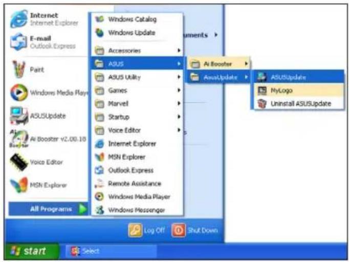
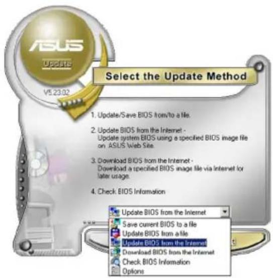
-
Select Update BIOS from the Internet option from the drop-down menu, then click Next.
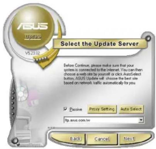
-
Select the ASUS FTP site nearest you to avoid network traffic, or click Auto Select. Click Next.
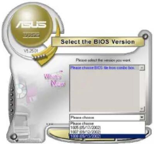
- From the FTP site, select the BIOS version that you wish to download. Click Next.
- Follow the screen instructions to complete the update process.

The ASUS Update utility is capable of updating itself through the Internet. Always update the utility to avail all its features.
Updating the BIOS through a BIOS fileOS file
To update the BIOS through a BIOS file:
- Launch the ASUS Update utility from the Windows ^ desktop by clicking Start > Programs > ASUS > ASUSUpdate > ASUSUpdate. The ASUS Update main window appears.
- Select Update BIOS from a file option from the drop-down menu, then click Next.
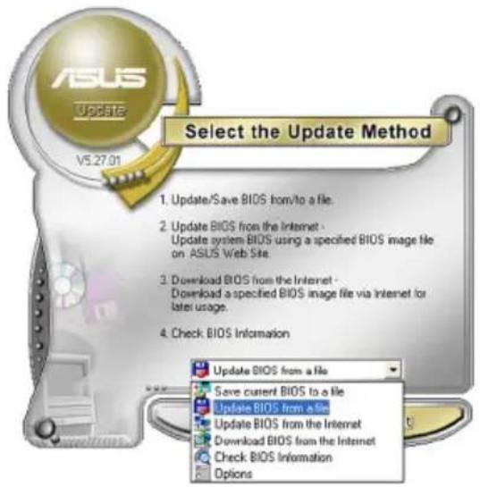
- Locate the BIOS file from the Open window, then click Save
- Follow the screen instructions to complete the update process.
5.2 BIOS setup program
This motherboard supports a programmable Low-Pin Count (LPC) chip that you can update using the provided utility described in section “4.1 Managing and updating your BIOS.”
Use the BIOS Setup program when you are installing a motherboard, reconfiguring your system, or prompted to "Run Setup." This section explains how to configure your system using this utility.
Even if you are not prompted to use the Setup program, you can change the configuration of your computer in the future. For example, you can enable the security password feature or change the power management settings. This requires you to reconfigure your system using the BIOS Setup program so that the computer can recognize these changes and record them in the CMOS RAM of the LPC chip.
The LPC chip on the motherboard stores the Setup utility. When you start up the computer, the system provides you with the opportunity to run this program. Press during the Power-On Self-Test (POST) to enter the Setup utility; otherwise, POST continues with its test routines.
If you wish to enter Setup after POST, reboot the system by doing any of the following procedures:
- Restart using rtgetOS standard shutdown procedure.
- Press < Ctrl > + × Alt > + × Del × Simultaneously.
- Press the reset button on the system chassis.chassis.
- Press the power button to turn the system off then back to re n back on.

Using the power button, reset button, or the keys to force reset from a running operating system can cause damage to your data or system. We recommend to always shut-down the system properly from the operating system.
The Setup program is designed to make it as easy to use as possible. Being a menu-driven program, it lets you scroll through the various sub-menus and make your selections from the available options using the navigation keys.

- The default BIOS settings for this motherboard apply for most conditions to ensure optimum performance. If the system becomes unstable after changing any BIOS settings, load the default settings to ensure system compatibility and stability. Select the Load Default Settings item under the Exit Menu. See section “5.8 Exit Menu.”
- The BIOS setup screens shown in this section are for reference purposes only, and may not exactly match what you see on your screen.
- Visit the ASUS website (www.asus.com) to download the latest BIOS file for this motherboard.
5.2.11 BIOS menu screen
![Menu items Menu item Items Menu item Confi gurafigun fields fields Bios Setup Utility Main Advanced Power Boot Exit System Time [11:10:19] System Date [Tue 01/01/2002] Legacy Diskette A [Disabled] Primary IDE Master : [Not Detected] Primary IDE Slave : [Not Detected] Third IDE Master : [Not Detected] Third IDE Slave : [Not Detected] Fourth IDE Master : [Not Detected] Fourth IDE Slave : [Not Detected] IDE Configuration System Information Use [ENTER]. [TAB], or [SHIFT-TAB] to select a field. Use [+] or [-] to configure system time. ←→ Select Screen ↑↓ Select Item +- Change Option F1 General Help F10 Save and Exit ESC Exit v02.58 (C) Copyright 1985-2004, American Megatrends, Inc. Sub-menu Items Navigation keys Sub-menu items](/content/2026/06/1196266/images/ea5d9926639126bf2be571287dc61a3b19b52db1f6bc41209a221e00b18223e6.jpg)
5.2.22 Menubarbar
The menu bar on top of the screen has the following main items:
Main For changing the basic system configuration
Advanced For changing the advanced system settings
Power For changing the Advanced Power Management (APM) configuration
Boot For changing the system boot configuration
Exit For selecting the exit options and loading default settings
To select an item on the menu bar, press the right or left arrow key on the keyboard until the desired item is highlighted.
5.2.33 Navigation keyskeys
At the bottom right corner of a menu screen are the navigation keys for that particular menu. Use the navigation keys to select items in the menu and change the settings.

Some of the navigation keys differ from one screen to another.
5.2.44 Menuritems
The highlighted item on the menu bar displays the specific items for that menu. For example, selecting Main shows the Main menu items.
The other items (Advanced, Power, Boot, and Exit) on the menu bar have their respective menu items.
![EOS SMOF OVIDMY Main Advanced Power Boot Exit System Time [11:10:19] System Date [Tue 01/01/2002] Legacy Diskette A [1.44M, 3.5 in] ► Primary IDE Master: [Not Detected] ► Primary IDE Slave : [Not Detected] ► Third IDE Master : [Not Detected] ► Third IDE Slave : [Not Detected] ► Fourth IDE Master : [Not Detected] ► Fourth IDE Slave : [Not Detected] ► IDE Configuration ► System Information Use [ENTER], [TAB], or [SHIFT-TAR] to select a field. Use [+] or [-] to configure system time. ◄ Select Screen ◄ Select Item +- Change Option P1 General Help P10 Save and Exit ESC Exit Mailmeau itemsms](/content/2026/06/1196266/images/b6234ece0be3a2b8d4acac2a5875bd326a0ca3fb956e8cb20c5f319c8e3afc01.jpg)
5.2.55 Sub-menuitemis ems
A solid triangle before each item on any menu screen means that the item has a sub-menu. To display the sub-menu, select the item and press
5.2.6 Configuration fields fields
These fields show the values for the menu items. If an item is user-configurable, you can change the value of the field opposite the item. You cannot select an item that is not user-configurable.
A configurable field is enclosed in brackets, and is highlighted when selected. To change the value of a field, select it then press
5.2.7 Popup-window
Select a menu item then press
5.2.88 Scrollbar bar
A scroll bar appears on the right side of a menu screen when there are items that do not fit on the screen. Press the Up/Down arrow keys or
![AVENHOOD BLUE SMOU OFFICACY APM Configuration Power Management/ARM [Enabled] Video Power Down Mode [Suspend] Hard Disk Power Down Mode [Suspend] Suspend Time Out(Minute) [Disabled] Throttle Slow Clock Ratio [50s] Power Button Function Restore on AC Power Loss Use [ENTER], [TAB], or [SHIFT-TAB] to select a field. Use [+] or [-] to configure system time. Power On by PS/2 Keyboard [Disabled] Power On by PS/2 Mouse [Disabled] Power On Ring [Disabled] Power On PML4 [Disabled] Power On MTC Alarm [Disabled] Select Screen Select Item +- Change Option F1 General Help F10 Save and Exit ESC Exit Pop-uppwinddown Scrollbarar](/content/2026/06/1196266/images/f2713b02107eb2373683a2e027c2ec883c23d595966575d3e41973996498a2f0.jpg)
5.2.9 General help
At the top right corner of the menu screen is a brief description of the selected item.
5.3 Main menu
When you enter the BIOS Setup program, the Main menu screen appears, giving you an overview of the basic system information.

Refer to section "5.2.1 BIOS menu screen" for information on the menu screen items and how to navigate through them.
| BIOS SETUP UTILITY Main Advanced Power Boot Exit | |
| System Time [11:10:19] System Date [Tue 01/01/2002] Legacy Diskette A [Disabled] | Use [ENTER]. [TAB], or [SHIFT-TAB] to select a field. Use [+] or [-] to configure system time. ↔ Select Screen ↑↓ Select Item +- Change Option F1 General Help F10 Save and Exit ESC Exit |
| Primary IDE Master : [Not Detected] Primary IDE Slave : [Not Detected] Third IDE Master : [Not Detected] Third IDE Slave : [Not Detected] Fourth IDE Master : [Not Detected] Fourth IDE Slave : [Not Detected] IDE Configuration | |
| System Information | |
5.3.11 SystemTime[i:xx:x[xxx]xx:xx]
Allows you to set the system time.
5.3.22 System Date [Day[xx/xx/xxxx]/xxxx]
Allows you to set the system date.
5.3.33 Legacy Diskette A [Disabled]
Sets the type of floppy drive installed. Configuration options: [Disabled] [360K, 5.25 in.] [1.2M, 5.25 in.] [720K, 3.5 in.] [1.44M, 3.5 in.] [2.88M, 3.5 in.]
5.3.44 Primary Third, Fourth DE Master/Slave/Slave
The BIOS automatically detects the connected IDE devices. There is a separate sub-menu for each IDE device. Select a device item, then press
| Primary IDE Master Device : Not Detected Type [Auto] LBA/Large Mode [Auto] Block (Multi-sector Transfer)M [Auto] PIO Mode [Auto] DMA Mode [Auto] SMART Monitoring [Auto] 32Bit Data Transfer [Enabled] | Select the type of device connected to the system. ←→ Select Screen ↑↓ Select Item +- Change Option F1 General Help F10 Save and Exit ESC Exit |
The BIOS automatically detects the values opposite the dimmed items (Device, Vendor, Size, LBA Mode, Block Mode, PIO Mode, Async DMA, Ultra DMA, and SMART monitoring). These values are not user-configurable. These items show N/A if no IDE device is installed in the system.
Type [Auto]
Selects the type of IDE drive. Setting to [Auto] allows automatic selection of the appropriate IDE device type. Select [CDROM] if you are specifically configuring a CD-ROM drive. Select [ARMD] (ATAPI Removable Media Device) if your device is either a ZIP, LS-120, or MO drive.
Configuration options: [Not Installed] [Auto] [CDROM] [ARMD]
LBA/Large Mode [Auto] to
Enables or disables the LBA mode. Setting to [Auto] enables the LBA mode if the device supports this mode, and if the device was not previously formatted with LBA mode disabled. Configuration options: [Disabled] [Auto]
Block(Multi-sector Transfer)[Auto][Auto]
Enables or disables data multi-sectors transfers. When set to [Auto], the data transfer from and to the device occurs multiple sectors at a time if the device supports multi-sector transfer feature. When set to [Disabled], the data transfer from and to the device occurs one sector at a time. Configuration options: [Disabled] [Auto]
PIO Model [A[uta]:o]
Selects the PIO mode. Configuration options: [Auto] [0] [1] [2] [3] [4]
DMA Model [A[uto] ]
Selects the DMA mode. Configuration options: [Auto] [SWDMA0] [SWDMA1] [SWDMA2] [MWDMA0] [MWDMA1] [MWDMA2] [UDMA0] [UDMA1] [UDMA2]
SMARTMonitoringi [Auto]
Sets the Smart Monitoring, Analysis, and Reporting Technology. Configuration options: [Auto] [Disabled] [Enabled]
32BitDataTransfer[Enabled]
Enables or disables 32-bit data transfer. Configuration options: [Disabled] [Enabled]
5.3.55 IDE Configuration
The items in this menu allow you to set or change the configurations for the IDE devices installed in the system. Select an item then press
| Main BIOS SETUP UTILITY | |
| IDE Configuration Configure SATA as [Standard IDE] Onboard IDE Operate Mode [Enhanced Mode] Enhanced Mode Support On [S-ATA] IDE Detect Time Out (Sec) [35] | Set [Compatible Mode] when Legacy OS (i.e. WIN ME, 98, NT4.0, MS DOS) is used. Set [Enhanced Mode] when Native OS (i.e. WIN2000, WIN XP) is used. ↔ Select Screen ↑↓ Select Item +- Change Option F1 General Help F10 Save and Exit ESC Exit |
| v02.58 (C) Copyright 1985-2004, American Megatrends, Inc. | |
Configure SATATAs [Standard IDE]d IDE]
Sets the configuration for the Serial ATA connectors supported by the Southbridge chip.
If you want to use the Serial ATA hard disk drives as Parallel ATA physical storage devices, set this item to [Standard IDE].
Onboard IDE Operate Mode [Enhanced Mode]
Allows selection of the onboard IDE operation mode depending on the installed operating system (OS). Set to [Enhanced] if you are using native OS, e.g. Windows® 2000/XP. Set to [Compatible] if you are using legacy OS, e.g. Windows ME/98/NT, MS-DOS. Configuration options: [Disabled] [Compatible] [Enhanced]
![ASUS RS100-E4/PI2 - Onboard IDE Operate Mode [Enhanced Mode] - 1](/content/2026/06/1196266/images/28294bf21a96094e9529896e97d2d2ed3d34362552c64d491d9552cbb10cd2b4.jpg)
Set the item Configure SATA as to [RAID] if you want to use or configure the SATA connectors under SuSE Linux Enterprise Server 9.0 SP1 operating system environment. Due to the OS limitation, you must set a SATA RAID to use any SATA device (at least two SATA devices are needed for the RAID configuration). Refer to Chapter 5 and Chapter 6 for details on how to set a SATA RAID.
Set Configure SATA As to [RAID], if you want to create a RAID 0 or RAID1, configurations using the Intel® Matrix Storage Manager or if you want to create a RAID 0 or RAID 1 configurations using the LSI Logic Embedded SATA RAID Setup Utility.
OnBoard Serial-ATA BOOTROM [Disabled]
Allows you to enable or disable the Onboard Serial-ATA BOOTROM. Configuration options: [Disabled] [Enabled]
The AHCI allows the onboard storage driver to enable advanced Serial ATA features that enhance storage performance on random workloads by allowing the drive to internally optimize the order of commands.
If you want the Serial ATA hard disk drives to use the Advanced Host Controller Interface (AHCI), set this item to [AHCI]. For details on AHCI, go to: www.intel.com/support/chipsets/imst/sb/CS-012304.htm www.intel.com/support/chipsets/imst/sb/CS-012305.htm
The SATA controller is set to Native mode when this item is set to [RAID] or [AHCI].
ALPE and ASP [Disabled]
Allows you to enable or disable the Aggressive Link Power Management and Aggressive Slumber/Partial Enabled. Configuration options: [Disabled] [Enabled]
Stagger Spinup Support [Disabled]
Allows you to enable or disable the Stagger Spinup support function. Configuration options: [Disabled] [Enabled]
AHCI Port 3 Interlock Switch [Disabled]
Allows you to enable or disable AHCI Port 3 Interlock Switch. Configuration options: [Disabled] [Enabled]
5.3.66 System Information
This menu gives you an overview of the general system specifications. The BIOS automatically detects the items in this menu.
| Main BIOS SETUP UTILITY | |
| AMIBIOS Version : 0115 Build Date : 08/14/06 Processor Type : Genuine Intel(R) CPU 2.80GHz Speed : 2800 MHz Count : 2 System Memory Usable Size : 1024MB | ←→ Select Screen ↑↓ Select Item +- Change Option F1 General Help F10 Save and Exit ESC Exit |
AMI BIOS S
Displays the auto-detected BIOS information.
Processor
Displays the auto-detected CPU specification.
System Memory
Displays the auto-detected total system memory.
5.4 Advanced menu
The Advanced menu items allow you to change the settings for the CPU and other system devices.

Take caution when changing the settings of the Advanced menu items. Incorrect field values can cause the system to malfunction.
| Main Advanced Power Boot Exit BIOS SETUP UTILITY | |
| USB Configuration MPS Configuration Remote Access Configuration Trusted Computing CPU Configuration Chipset Onboard Devices Configuration PCIPnP | Configure the Multi-Processor Table. ←→ Select Screen ↑↓ Select Item +- Change Option F1 General Help F10 Save and Exit ESC Exit |
5.4.11 USB Configuration
| Advanced BIOS SETUP UTILITY | |
| USB Configuration | Enables USB host controller. |
| Module Version - 2.24.0-10.4 | |
| USB Devices Enabled: None | |
| USB Function [4 USB Ports] Legacy USB Support [Enabled] USB2.0 Controller [Enabled] USB2.0 Controller mode [HiSpeed] BIOS EHCI Hand-Off [Enabled] | |
| ←→ Select Screen ↑↓ Select Item +- Change Option F1 General Help F10 Save and Exit ESC Exit | |
| v02.58 (C) Copyright 1985-2004, American Megatrends, Inc. | |
USB Function [4 [USB Ports]
Allows you to enable a specific number of USB ports, or disable the USB function. Configuration options: [Disabled] [2 USB Ports] [4 USB Ports]
Legacy USB Support [Enabled]
Allows you to enable or disable support for legacy USB. The AUTO option disables legacy support if there is no USB device connected. Configuration options: [AUTO] [2 USB Ports] [4 USB Ports]
USB 2.0 Controller [Enabled]
Allows you to enable or disable the USB 2.0 controller.
Configuration options: [Enabled] [Disabled]
USB2.0 Controller mode [HiSpeed]
Allows you to select the USB2.0 controller mode.
Configuration options: [HiSpeed] [FullSpeed]
BIOSSEIBICHand+Off[Enabled]
Allows yout to enable or disable the BIOS EHCI Hand-Off support function. Configuration options: [Disabled] [Enabled]
5.4.2 MPS Configuration
| BIOS SETUP UTILITY Advanced | |
| MPS Configuration MPS Revision [1.4] | Select MPS Revision. ↔ Select Screen ↑↓ Select Item +- Change Option F1 General Help F10 Save and Exit ESC Exit |
| v02.58 (C)Copyright 1985-2004, American Megatrends, Inc. | |
MPS Revision [1 [4].4]
Allows you to select the multi-processor system version.
Configuration options: [1.1] [1.4]
5.4.33 Remote Access Configuration
The items in this menu allows you to configure the Remote Access features. Select an item then press
| BIOS SETUP UTILITY Advanced | |
| Configure Remote Access type and parameters Remote Access [Disabled] Serial port number [COM1] Base Address, IRQ [3F8h,4] Serial Port Mode [115200 8, n,1] Flow Control [None] Redirection After BIOS POST [Always] Terminal Type [ANSI] VT-UTF8 Combo Key Support [Enabled] Media Type [Serial] | Select Remote Access type. ↔ Select Screen ↑↓ Select Item +- Change Option F1 General Help F10 Save and Exit ESC Exit |
| v02.58 (C)Copyright 1985-2004, American Megatrends, Inc. | |
Remote Access [Disabled] led]
Enables or disables the remote access feature.
Configuration options: [Disabled] [Enabled]
![ASUS RS100-E4/PI2 - Remote Access [Disabled] led] - 1](/content/2026/06/1196266/images/08f411fe41edaa6bf1ebd2f3b13e8e9dfa3b412fdb1e22f353d7927ed47e4a14.jpg)
The following items appear only when the Remote Access item is set to [Enabled].
Serial port numberb[COM10M1]
Allows you to select a serial port for console redirection. Configuration options: [COM1] [COM2]
SerialPortMode[1520080n,1], n,1]
Allows you to select a serial port mode. Configuration options: [1152008,n,1] [57600 8,n,1] [38400 8,n,1] [19200 8,n,1] [09600 8,n,1]
FlowControl [None]
Allows you to set the flow control for console redirection. Configuration options: [None] [Hardware] [Software]
Redirection After BIOS POST [Always]ways]
Sets the redirection mode after the BIOS Power-On Self-Test (POST). Some operating systems may not work when this item is set to Always.
Configuration options: [Disabled] [Boot Loader] [Always]
TerminalType[ANSI]
Allows you to select the target terminal type. Configuration options: [ANSI] [VT100] [VT-UTF8]
VT-UTF8ComboKeySupport[Enab[Ed]abled]
Allows you to enable or disable VT-UTF8 Combination Key Support for ANSI/VT100 terminals. Configuration options: [Enabled] [Disabled]
Media Type [Serial]
Allows you to select the media for console redirection. Configuration options: [Serial] [LAN] [Serial + LAN]
5.4.44 Trusted Computing
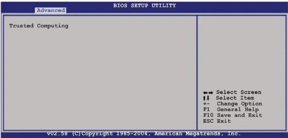
Use this option to configure settings related to trusted computing innovations.

You need to install ASUS TPM card to make this feature function.
5.4.55 CPU Configuration
The items in this menu show the CPU-related information that the BIOS automatically detects.
| Configure Advanced CPU settings | |
| Manufacturer: Intel Brand String: Genuine Intel(R) CPU 2.80GHz Frequency : 2800 MHz FSB Speed : 800 MHz Cache L1 : 32 KB Cache L2 : 2048 KB Cache L3 : 0 KB | Sets the ratio between CPU Core Clock and the FSB Frequency. NOTE: If an invalid ratio is set in CMOS then actual and setpoint values may differ. |
| Ratio Status: Unlocked (Max:14, Min:14) Ratio Actual Value: 14 Max CPUID Value Limit [Disabled] Execute Disabled Function [Disabled] Enhance C1 Control [Auto] Virtualization Technology [Enabled] CPU Internal Thermal Control [Auto] | ←→ Select Screen ↑↓ Select Item +- Change Option F1 General Help F10 Save and Exit ESC Exit |
Max CPUID Value Limit [Disabled]
Setting this item to [Enabled] allows legacy operating systems to boot even without support for CPUs with extended CPUID functions.
Configuration options: [Disabled] [Enabled]
Execute Disabled Function [Disabled]
Allows you to enable or disable the Execute Disabled function.
Configuration options: [Disabled] [Enabled]
Enhanced C1Control[Auto]
Allows you to disable or set to Auto the Enhanced C1 Control.
Configuration options: [Auto] [Disabled]
Virtualization Technology | [Enab[Ed]abled]
Allows you to enable or disable the Virtualization Technology feature.
Configuration options: [Disabled] [Enabled]
CPU Internal Thermal Control [Autb] [Auto]
Allows you to set CPU internal thermal control. if set to Auto, BIOS automatically check CPU's capability to enable TM or TM2 support. In TM mode, CPU power consumption is reduced; in TM2 mode, CPU core ratio and VID is reduced. Configuration options: [Auto] [Disabled]
5.4.6 Chipsets Configuration
The Chipset Configuration menu allows you to change the advanced chipset settings. Select an item then press
| Advanced Chipset Settings | Manual DRAM Frequency Setting or Auto by SPD |
| DRAM Frequency [Auto] | |
| Configure DRAM Timing by SPD [Enabled] | |
| Spread Spectrum [Disabled] | |
| Onboard LAN Boot ROM [Enabled] | |
| PEG Port Configuration | |
| PEG Port [Enabled] | Select Screen ↑↓ Select Item +- Change Option F1 General Help F10 Save and Exit ESC Exit |
| PEG Port VC1 Map [TC7] PEG Force x1 [Disabled] Memory Remap Feature [Enabled] | |
| v02.58 (C) Copyright 1985-2004, American Megatrends, Inc. | |
DRAMFFrequency [Auto]
Allows you to set the DDR operating frequency. Configuration options: [Auto] [533 MHz] [667 MHz]
Configure DRAMTiming bySPD [Enabled]
When this item is enabled, the DRAM timing parameters are set according to the DRAM SPD (Serial Presence Detect). When disabled, you can manually set the DRAM timing parameters through the DRAM sub-items. The following sub-items appear when this item is disabled. Configuration options: [Disabled] [Enabled]
DRAM CAS# Latency [5 Clocks] Controls the latency between the SDRAM read command and the time the data actually becomes available. Configuration options: [5 Clocks] [4 Clocks] [3 Clocks] [6 Clocks] DRAM RAS# to CAS# Delay [4 Clocks] Controls the latency between the DDR SDRAM active command and the read/write command. Configuration options: [2 Clocks] [3 Clocks] [4 Clocks] [5 Clocks] DRAM RAS# Activate to Precharge Delay [15 DRAM Clocks] Configuration options: [1 Clocks] [2 Clocks] \~ [15 Clocks] DRAM Write Recovery Time [4 Clocks] Configuration options: [2 Clocks] [3 Clocks] [4 Clocks] [5 Clocks]
Spread Spectrum [Disabled]
Allows you to enable or disable the spread spectrum. Configuration options: [Disabled] [Enabled]
Onboard LAN Boot ROM [Enabled]
Allows you to enable or disable the option ROM in the onboard LAN controller. Configuration options: [Disabled] [Enabled]
PEG Port Configuration
PEG Port [Enabled]
Allows you to enable or disable the PCI Express Graphic port.
Configuration options: [Enabled] [Disabled]
MemoryRenameFeature [Enabled]
Allows you to remap the overlap PCI memory over the total physical memory. Configuration options: [Disabled] [Enabled]
![ASUS RS100-E4/PI2 - MemoryRenameFeature [Enabled] - 1](/content/2026/06/1196266/images/e3f13dce557d4be8ec1262147c793613853e183eb26274a929092a97b3e82814.jpg)
Disable this item if you are using RedHat Linux Advanced Server 3.0 UP5/UP6 operating system.
5.4.77 Onboard Devices Configuration
The Onboard Devices Configuration menu allows you to change the onboard devices settings. Select an item then press
| BIOS SETUP UTILITY Advanced | |
| Configure Win83627EHG-A Super IO Chipset Serial Port1 Address [3F8/IRQ4] Serial Port2 Address [2F8/IRQ3] Serial Port2 Mode [Normal] Parallel Port Address [378] Parallel Port Mode [ECP] ECP Mode DMA Channel [DMA3] Parallel Port IRQ [IRQ7] | ENABLE: Allow remapping of overlapped PCI memory above the total physical memory. DISABLE: Do not allow remapping of memory. |
Serial Port Address [3F8[/IRQ4]/IRQ4]
Allows you to select the Serial Port1 base address.
Configuration options: [Disabled] [3F8/IRQ4] [3E8/IRQ4] [2E8/IRQ3]
Serial Port2Address [2F8/IRQ3]IRQ3]
Allows you to select the Serial Port2 base address.
Configuration options: [Disabled] [2F8/IRQ3] [3E8/IRQ4] [2E8/IRQ3]
Serial Port2 Mode [Normal]
Allows you to select the Serial Port2 mode.
Configuration options: [Normal] [IrDA] [ASK IR]
Parallel Port Address [378][378]
Allows you to select the Parallel Port base addresses.
Configuration options: [Disabled] [378] [278] [3BC]
Parallel Port Mode [ECP]
Allows you to select the Parallel Port mode.
Configuration options: [Normal] [Bi-directional] [ECP] [EPP]
EPP Version [1 [9].9]
Allows selection of the Parallel Port EPP version. This item appears when the Parallel Port Mode is set to [EPP] or [ECP & EPP].
Configuration options: [1.9] [1.7]
ECP Mode DMA Channel [DMA3MA3]
Appears when the Parallel Port Mode is set to [ECP] or [ECP & EPP].
This item allows you to set the Parallel Port ECP DMA.
Configuration options: [DMA0] [DMA1] [DMA3]
Parallel Port IRQ [IRQ7]
Sets the Parallel port IRQ. Configuration options: [IRQ5] [IRQ7]
5.4.83 PCPPhPNP
The PCI PnP menu items allow you to change the advanced settings for PCI/PnP devices. The menu includes setting IRQ and DMA channel resources for either PCI/PnP or legacy ISA devices, and setting the memory size block for legacy ISA devices.

Take caution when changing the settings of the PCI PnP menu items. Incorrect field values can cause the system to malfunction.
BIOS SETUP UTILITY
Advanced
Advanced PCI/PnP Settings
WARNING: Setting wrong values in below sections may cause system to malfunction.
Plug And Play O/S [No]
PCI Latency Timer [64]
Allocate IRQ to PCI VGA [Yes]
Palette Snooping [Disabled]
IRQ-3 assigned to [PCI Device]
IRQ-4 assigned to [PCI Device]
IRQ-5 assigned to [PCI Device]
IRQ-7 assigned to [PCI Device]
IRQ-9 assigned to [PCI Device]
IRQ-10 assigned to [PCI Device]
IRQ-11 assigned to [PCI Device]
IRQ-14 assigned to [PCI Device]
IRQ-15 assigned to [PCI Device]
NO: Lets the BIOS
configure all the
devices in the system.
YES: Lets the
operating system
configure Plug and Play
(PnP) devices not
required for boot if
your system has a Plug
and Play operating
system.

Select Screen Select Item
+- Change Option
F1 General Help
F10 Save and Exit
ESC Exit
(C)Copyright 1985-2002, American Megatrends, Inc.
Plug And Play O/S [No[No]
When set to [No], BIOS configures all the devices in the system. When set to [Yes] and if you install a Plug and Play operating system, the operating system configures the Plug and Play devices not required for boot.
Configuration options: [No] [Yes]
PCI Latency Timem[64][64]
Allows you to select the value in units of PCI clocks for the PCI device latency timer register. Configuration options: [32] [64] [96] [128] [160] [192] [224] [248]
Allocate RQ to PCI VGA[Yes][Yes]
When set to [Yes], BIOS assigns an IRQ to PCI VGA card if the card requests for an IRQ. When set to [No], BIOS does not assign an IRQ to the PCI VGA card even if requested. Configuration options: [No] [Yes]
Palette Snoopingi [Disabled]
When set to [Enabled], the pallette snooping feature informs the PCI devices that an ISA graphics device is installed in the system so that the latter can function correctly. Configuration options: [Disabled] [Enabled]
IRQ-xx assigned to [PCI[Device]
When set to [PCI Device], the specific IRQ is free for use of PCI/PnP devices. When set to [Reserved], the IRQ is reserved for legacy ISA devices. Configuration options: [PCI Device] [Reserved]
5.5 Power Configuration
The Power Configuration menu items allow you to change the settings for the ACPI and Advanced Power Management (APM) features. Select an item then press
![Main Advanced Power BIOS SETUP UTILITY Boot Exit ACPI APIC Support [Enabled] ► APM Configuration ► Hardware Monitor Include ACPI APIC table pointer to RSDT pointer list. ←→ Select Screen ↑↓ Select Item +- Change Option F1 General Help F10 Save and Exit ESC Exit](/content/2026/06/1196266/images/d18ce3577b409f85f03280701239f2932609d2c3fe71fec8fa74099e013b790a.jpg)
ACPII APIO Supporto[Enabled]
Allows you to enable or disable the Advanced Configuration and Power Interface (ACPI) support in the Advanced Programmable Interrupt Controller (APIC). When set to Enabled, the ACPI APIC table pointer is included in the RSDT pointer list. Configuration options: [Disabled] [Enabled]
5.5.11 APM Configuration
![BIOS SETUP UTILITY Power APM Configuration Restore on AC Power Loss [Last State] Resume On By RTC Alarm [Disabled] Power On By PS/2 Keyboard [Disabled] Power On By PS/2 Mouse [Disabled] Resume On Ring [Disabled] Resume On LAN [Disabled] Power On By PCI Devices [Disabled] Keyboard Wakeup Password : Not Installed Options Power Off Power On Last State ←→ Select Screen ↑↓ Select Item +- Change Option F1 General Help F10 Save and Exit ESC Exit v02.58 (C)Copyright 1985-2004, American Megatrends, Inc.](/content/2026/06/1196266/images/55a4db2c727f6bf284e11fe1b3e5195f23c2fe112eb48a34588c94b1cb632c23.jpg)
Restore on ACAPowerLoss[Last[State]State]
When set to Power Off, the system goes into off state after an AC power loss. When set to Power On, the system goes on after an AC power loss. When set to Last State, the system goes into either off or on state,
whatever the system state was before the AC power loss. Configuration options: [Power Off] [Power On] [Last State]
Resume On By RTC Alarm [Disabled]
Allows you to enable or disable RTC to generate a wake event. When this item is set to [Enabled], the items RTC Alarm Date, RTC Alarm Hour, RTC Alarm Minute, and RTC Alarm Second appear with set values.
Configuration options: [Disabled] [Enabled]
![ASUS RS100-E4/PI2 - Resume On By RTC Alarm [Disabled] - 1](/content/2026/06/1196266/images/2724b42091778938fb720105970bd5b76b7be1bf8c1429a32747ffdaa32600f2.jpg)
The following items appear only when the Resume On By RTC Alarm item is set to Enabled.
RTC Alarm Date (Days) [15]
To set the alarm date, highlight this item and press the <+> or <-> key to make the selection. Configuration options: [Everyday] [1] [2] [3]...[31]
System Time [12:30:30]
To set the alarm time, highlight this item and press the <+> or <-> key to make the selection.
Power On By PS/2 Keyboard [Disabled]
Allows you to use specific keys on the keyboard to turn on the system. This feature requires an ATX power supply that provides at least 1A on the +5VSB lead. Configuration options: [Disabled] [Enabled]
Power On By PS/2 Mouse [Disabled]
When set to [Enabled], this parameter allows you to use the PS/2 mouse to turn on the system. This feature requires an ATX power supply that provides at least 1A on the +5VSB lead. Configuration options: [Disabled] [Enabled]
ResumeOn Ring [Disabled] led]
When set to [Enabled], the system enables the RI to generate a wake event while the computer is in Soft-off mode.
Configuration options: [Disabled] [Enabled]
Power on ByBPC Devices [Disabled]
When set to [Enabled], this parameter allows you to turn on the system through a PCI LAN or Modem card. This Feature requires an ATX power supply that provides at least 1A on the +5VSB lead.
Configuration options: [Disabled] [Enabled]
5.5.22 Hardware Monitor
![BIOS SETUP UTILITY Power Hardware Monitor CPU Temperature [49°C/120°F] MB1 Temperature [47°C/114°F] MB2 Temperature [47°C/114°F] CPU Fan1 Speed [3884RPM] CPU Fan2 Speed [N/A] Front Fan1 Speed [N/A] Front Fan2 Speed [N/A] Rear Fan1 Speed [N/A] Rear Fan2 Speed [N/A] Smart Fan Control [Smart Fan] CPU Target Temperature [055] MB Target Temperature [050] VCORE Voltage [ 1.320V] 3.3V Voltage [ 3.345V] 5V Voltage [ 5.094V] CPU1 Temperature ↔ Select Screen ↑↓ Select Iten +- Change Option F1 General Help F10 Save and Exit ESC Exit vMM.mm Copyright 1985-2002, American Megatrends, Inc.](/content/2026/06/1196266/images/ff7050c8ad4fd9a7cbaec1dc1d7249d220332a5ad416faa603f5272ea2cc8082.jpg)
Use the arrow down key to display additional items.
![5VSB Voltage [ 4.980V] VBAT Voltage [ 3.120V] 12V Voltage [12.053V] F10 Save and Exit ESC Exit vMM.mm Copyright 1985-2002, American Megatrends, Inc.](/content/2026/06/1196266/images/1fc7c0a3cfe16af7249a2a13fb0caaf1a85493b60f17d29cd6155136ca47def1.jpg)
CPU Temperature: [xx[x°C/xxx°F]xx°F]
MB1 Temperature[xx[x°C/xxx°F]xx°F]
The onboard hardware monitor automatically detects and displays the motherboard and CPU temperatures. Select [Ignored] if you do not wish to display the detected temperatures.
CPU Fan1/2 Speed [xx[xRPM]Rm[N/A] [N/A]
Front Fan 1/2/Speed [xxx[xRPM]or[N]/A] [N/A]
RearF#n1/2/Speed [xxx[xRPM]Ron[N/A] [N/A]
The onboard hardware monitor automatically detects and displays the CPU, front, and rear fan speed in rotations per minute (RPM). If the fan is not connected to the motherboard, the field shows N/A.
SmartFian Control [Enabled]
Allows you to enable or disable the ASUS Smart Fan feature that smartly adjusts the fan speeds for more efficient system operation. Configuration options: [Disabled] [Enabled]
![ASUS RS100-E4/PI2 - SmartFian Control [Enabled] - 1](/content/2026/06/1196266/images/94417aef8979ba77c67335f98f2dcef0a4c31ff56ca71a51149878ca5941f805.jpg)
The CPU Temperature and MB Temperature items appear when you set the Smart Fan Control item to [Enabled].
CPU Target Temperature: [XXX][XXX] MB1 Target Temperature: [XXX][XXX]
Displays the detected CPU and system threshold temperature when the Smart Fan Control is enabled.
VCOREE 1 Voltage, VCORE2 Voltage, 3.3V, Voltage, 5V, Voltage, 5V, VSBS Voltage, 4BAT Voltage, 1.2V, Voltage Voltage
The onboard hardware monitor automatically detects the voltage outputs through the onboard voltage regulators.
5.6 Boot menu
The Boot menu items allow you to change the system boot options. Select an item then press
| Main Advanced Power BIOS SETUP UTILITY Boot Export | |
| Boot Settings | Specifies the Boot Device Priority sequence. A virtual floppy disk drive (Floppy Drive B:) may appear when you set the CD-ROM drive as the first boot device. ←→ Select Screen ↑↓ Select Item +- Change Option F1 General Help F10 Save and Exit ESC Exit |
| ▶ Boot Device Priority ▶ Hard Disk Drives | |
| ▶ Boot Settings Configuration ▶ Security | |
5.6.11 Boot Device Priority
![BIOS SETUP UTILITY Boot Boot Device Priority 1st Boot Device [Removable dev.] 2nd Boot Device [ATAPI CD-ROM] 3rd Boot Device [RAID LSI Logic MB] 4th Boot Device [Network: MBA V8.3.9] 5th Boot Device [Network: MBA V8.3.9]](/content/2026/06/1196266/images/aca0f76679de50bf2fd55b00615763777476e4963f4eca91b58ebe870db2c94c.jpg)
1st Boot Device [as[FLORRYCDrive]Drive] 2nd Boot Device [NetWorkMBA v73A5]7.7.5] 3rd Boot Device [NetWorkMBA w73A5]7.7.5]
These items specify the boot device priority sequence from the available devices. Configuration options: [xxxxx Drive] [Disabled]
5.6.22 Hard Disk Drives
| BIOS SETUP UTILITY Boot | |
| Boot Device Priority | Specifies the Boot Device Priority sequence from available Hard Drives. |
| 1st Drive [HDD:XXXXXXXX Drive] 2nd Drive [HDD:XXXXXXXX Drive] | |
1st \~ xxth Driveive [HDD::XXXXXXXXDriveive]
These items specify the boot device priority sequence from the available hard disk drives. The number of device items that appears on the screen depends on the number of devices installed in the system. Configuration options: [xxxxx Drive] [Disabled]
5.6.33 Boot Settings configuration
| BIOS SETUP UTILITY Boot | |
| Boot Settings Configuration Quick Boot [Enabled] Full Screen Logo [Enabled] AddOn ROM Display Mode [Force BIOS] Bootup Num-Lock [On] PS/2 Mouse Support [Auto] Wait For 'F1' If Error [Enabled] Hit 'DEL' Message Display [Enabled] Interrupt 19 Capture [Disabled] | Allows BIOS to skip certain tests while booting. This will decrease the time needed to boot the system. ↔ Select Screen ↑↓ Select Item +- Change Option F1 General Help F10 Save and Exit ESC Exit |
| v02.58 (C) Copyright 1985-2004, American Megatrends, Inc. | |
QuickBoot[Enabled]ed]
Enabling this item allows the BIOS to skip some power on self tests (POST) while booting to decrease the time needed to boot the system. When set to [Disabled], BIOS performs all the POST items.
Configuration options: [Disabled] [Enabled]
FullScreenLogo [Enabled]
Allows you to enable or disable the full screen logo display feature. Configuration options: [Disabled] [Enabled]
![ASUS RS100-E4/PI2 - FullScreenLogo [Enabled] - 1](/content/2026/06/1196266/images/2de2dbb6d383cb98f7f283f00bfdce4946d053d35e746556fda7fcb11f587589.jpg)
Set this item to [Enabled] to use the ASUS MyLogo2™ feature.
AddOnROM Display|Mode [For[FBIOS] BIOS]
Allows you to set display mode for optional ROM. Configuration options: [Force BIOS] [Keep Current]
BootupNumLock[On]
Allows you to select the power-on state for the NumLock. Configuration options: [Off] [On]
PS/2 Mouse Support [Auto]uto]
Allows you to enable or disable support for PS/2 mouse. Configuration options: [Disabled] [Enabled] [Auto]
Wait:for F1F 1F Error[Enabled]
When set to Enabled, the system waits for the F1 key to be pressed when error occurs. Configuration options: [Disabled] [Enabled]
Hit: 'DEELMessage Display [Enab[Ed]abled]
When set to Enabled, the system displays the message "Press DEL to run Setup" during POST. Configuration options: [Disabled] [Enabled]
Interrupt 19 Capture [Disabled]
When set to [Enabled], this function allows the option ROMs to trap Interrupt 19. Configuration options: [Disabled] [Enabled]
5.6.44 Security
The Security menu items allow you to change the system security settings. Select an item then press
| Security Settings | <Enter> to change password. <Enter> again to disable password. |
| Supervisor Password : Not Installed User Password : Not Installed | |
| Change Supervisor Password Change User Password | ←→ Select Screen ↑↓ Select Item +- Change Option F1 General Help F10 Save and Exit ESC Exit |
Change Supervisor Password
Select this item to set or change the supervisor password. The Supervisor Password item on top of the screen shows the default Not Installed. After you set a password, this item shows Installed.
To set a Supervisor Password:
- Select the Change Supervision Password item, then press
. - From the password box, type a password composed of at least six letters and/or numbers, then press
. - Confirm the password when prompted.
The message "Password Installed" appears after you successfully set your password.
To change the supervisor password, follow the same steps as in setting a user password.
To clear the supervisor password, select the Change Supervisor Password then press

If you forget your BIOS password, you can clear clear it by erasing the CMOS Real Time Clock (RTC) RAM. See section "2.6 Jumpers" for information on how to erase the RTC RAM.
After you have set a supervisor password, the other items appear to allow you to change other security settings.
| Security Settings Supervisor Password : Installed User Password : Not Installed Change Supervisor Password User Access Level [Full Access] Change User Password Clear User Password Password Check [Setup] | <Enter> to change password. <Enter> again to disable password. ←→ Select Screen ↑↓ Select Item +- Change Option F1 General Help F10 Save and Exit ESC Exit |
User Access Level [Full [Access]cess]
This item allows you to select the access restriction to the Setup items. Configuration options: [No Access] [View Only] [Limited] [Full Access]
No Access prevents user access to the Setup utility.
View Only allows access but does not allow change to any field.
Limited allows changes only to selected fields, such as Date and Time.
Full Access allows viewing and changing all the fields in the Setup utility.
Change User Password
Select this item to set or change the user password. The User Password item on top of the screen shows the default Not Installed. After you set a password, this item shows Installed.
To set a User Password:
-
Select the Change User Password item and press
. -
On the password box that appears, type a password composed of at least six letters and/or numbers, then press
. - Confirm the password when prompted.
The message “Password Installed” appears after you set your password successfully.
To change the user password, follow the same steps as in setting a user password.
ClearUserPassword
Select this item to clear the user password.
Password Check [Setup]
When set to [Setup], BIOS checks for user password when accessing the Setup utility. When set to [Always], BIOS checks for user password both when accessing Setup and booting the system.
Configuration options: [Setup] [Always]
5.7 Exit menu
The Exit menu items allow you to load the optimal or failsafe default values for the BIOS items, and save or discard your changes to the BIOS items.
| Main Advanced Power BIOS SETUP UTILITY Boot Exit | |
| Exit Options Exit & Save Changes Exit & Discard Changes Discard Changes Load Setup Defaults | Exit system setup after saving the changes. F10 key can be used for this operation. ↔ Select Screen ↑↓ Select Item +- Change Option F1 General Help F10 Save and Exit ESC Exit |

If you made changes to any of the settings in the menus, pressing
Exit & Save Changes
Select this option then press
When a confirmation window appears, select [OK] then press
Exit & Discard Changes
Select this option then press
When a confirmation window appears, select [OK] then press
Discard Changes
Select this option then press
When a confirmation window appears, select [OK] then press
Load Setup Defaults
Select this option then press
When a confirmation window appears, select [OK] then press
Chapter 6
This chapter provides instructions for setting up, creating and configuring RAID sets using the available utilities.
CARD conjugation
6.1 RAID configurations
The server system/motherboard comes with the Intel ^® ICH7R and the LSI Logic Embedded SATA RAID technology built-in the Intel ^® ICH7R SouthBridge chipset that allows you to configure IDE and Serial ATA hard disk drives as RAID sets. The motherboard supports the following RAID configurations:
6.1.11 RAID definitions
RAID 0 (Data striping) optimizes two identical hard disk drives to read and write data in parallel, interleaved stacks. Two hard disks perform the same work as a single drive but at a sustained data transfer rate, double that of a single disk alone, thus improving data access and storage. Use of two new identical hard disk drives is required for this setup.
RAID 1 (Data mirroring) copies and maintains an identical image of data from one drive to a second drive. If one drive fails, the disk array management software directs all applications to the surviving drive as it contains a complete copy of the data in the other drive. This RAID configuration provides data protection and increases fault tolerance to the entire system. Use two new drives or use an existing drive and a new drive for this setup. The new drive must be of the same size or larger than the existing drive.
Intel® Matrix Storage. The Intel® Matrix Storage technology supported by the ICH7R chip allows you to create a RAID 0 and a RAID 1 set using only two identical hard disk drives. The Intel® Matrix Storage technology creates two partitions on each hard disk drive to create a virtual RAID 0 and RAID 1 sets. This technology also allows you to change the hard disk drive partition size without losing any data.

If you want to boot the system from a hard disk drive included in a created RAID set, copy first the RAID driver from the support CD to a floppy disk before you install an operating system to the selected hard disk drive. Refer to section “6.1 RAID driver installation” for details.
6.1.22 Installing Serial ATAl hard disks d disks
The motherboard supports Serial ATA hard disk drives. For optimal performance, install identical drives of the same model and capacity when creating a disk array.
To install the SATA hard disks for a RAID configuration:
- Install the SATA hard disks into the drive bays.
- Connect the SATA signal cables.
- Connect a SATA power cable to the power connector on each drive.
6.1.3 Setting the RAID item in BIOS in BIOS
You must set the RAID item in the BIOS Setup before you can create a RAID set(s). To do this:
- Enter the BIOS Setup during POST.
- Go to the Main Menu, select IDE Configuration, then press
. - Select the item Configure SATA As, then press
to display the configuration options. - Select RAID from the Configure SATA As item options, then press
. - Select the item Onboard Serial ATA BOOTROM, press
, then select Enabled from the options. - Save your changes, then exit the BIOS Setup.

Refer to Chapter 4 for details on entering and navigating through the BIOS Setup.
6.1.44 RAID configuration utility
Depending on the RAID_SEL1 jumper setting and the operating system, you can select a utility to create a RAID set. Refer to section "2.6 Jumpers" for details on the RAID_SEL1 jumper settings.
Use the Intel ^® Matrix Storage Manager to create a RAID 0 or RAID 1 set under Windows ^® 2000/2003 Server/XP operating system.
Use the LSI Logic Embedded SATA RAID Setup Utility to create a RAID 0 or RAID 1 under Windows® 2000/2003 Server or Red Hat® Enterprise ver. 3.0 operating system.
Refer to the succeeding sections for details on how to use the RAID configuration utilities.
6.2 Intel ^® Matrix Storage Manager Option ROM Utility
The Intel ^® Matrix Storage Manager Option ROM utility allows you to create RAID 0 or RAID 1 from Serial ATA hard disk drives that are connected to the Serial ATA connectors supported by the Southbridge.
To enter the Intel ^® Application Accelerator RAID Option ROM utility:
- Install all the Serial ATA hard disk drives.
- Turn on the system.
- During POST, press
+ to display the utility main menu.
![Intel(R) Matrix Storage Manager Option ROM v5.0.0.1032 ICH7R wRAID5 Copyright(C) 2003-05 Intel Corporation. All Rights Reserved. [ MAIN MENU ] 1. Create RAID Volume 2. Delete RAID Volume 3. Reset Disks to Non-RAID 4. Exit [ DISK/VOLUME INFORMATION ] RAID Volumes: None defined. Physical Disks: Port Drive Model Serial # 0XXXXXXXXXXXX XXXXXXXXX XX.XXGB Non-RAID Disk 1XXXXXXXXXXXX XXXXXXXXX XX.XXGB Non-RAID Disk 2XXXXXXXXXXXX XXXXXXXXX XX.XXGB Non-RAID Disk 3XXXXXXXXXXXX XXXXXXXXX XX.XXGB Non-RAID Disk [↑↓]-Select [ESC]-Exit [ENTER]-Select Menu](/content/2026/06/1196266/images/4631b56cf62a35e96b99c12eb7b31cbf1bf7d52b4a46322b18c7319e1aa81d6c.jpg)
The navigation keys at the bottom of the screen allow you to move through the menus and select the menu options.

The RAID BIOS setup screens shown in this section are for reference only and may not exactly match the items on your screen.
6.2.11 Creating iA RADRO set (striped)
To create a RAID 0 set:
- From the utility main menu, select 1. Create RAID Volume, then press
. This screen appears.
![Intel(R) Matrix Storage Manager Option ROM v5.0.0.1032 ICH7R wRAID5 Copyright(C) 2003-05 Intel Corporation. All Rights Reserved. [ CREATE ARRAY MENU ] Name: Volume0 RAID Level: RAID0(Stripe) Disks: Select Disks Strip Size: 128KB Capacity: 0.0 GB Create Volume [ DISK/VOLUME INFORMATION ] Enter a string between 1 and 16 characters in length that can be used to uniquely identify the RAID volume. This name is case sensitive and cannot contain special characters. [↑↓]-Change [TAB]-Next [ESC]-Previous Menu [Enter]-Select](/content/2026/06/1196266/images/69d723267354134135df87c967234f60487d97968ff65d47c8a3806b149f8c89.jpg)
- Enter a name for the RAID 0 set, then press
. - When the RAID level item is highlighted, press the up/down arrow key to select RAID 0(Stripe), then press
. - When the Disks item is highlighted, press
to select the hard disk drives to configure as RAID. This SELECT DISKS screen appears.
![[ SELECT DISKS ] Port Drive Model Serial # Size Status 0XXXXXXXXXX XXXXXXXX XX.XGB Non-RAID Disk 1XXXXXXXXXX XXXXXXXX XX.XGB Non-RAID Disk 2XXXXXXXXXX XXXXXXXX XX.XGB Non-RAID Disk 3XXXXXXXXXX XXXXXXXX XX.XGB Non-RAID Disk Select 2 to 4 disks to use in creating the volume. [↑↓]-Previous/Next [SPACE]-Selects [ENTER]-Selection Complete](/content/2026/06/1196266/images/2073696177945d7d715d133b99fd045f720cbfb83089829230b5fe00605cc739.jpg)
-
Use the up/down arrow key to highlight a drive, then press
to select. A small triangle marks the selected drive. Press after completing your selection. -
Use the up/down arrow key to select the stripe size for the RAID 0 array, then press
. The available stripe size values range from 8 KB to 128 KB. The default stripe size is 128 KB.

TIP: We recommend a lower stripe size for server systems, and a higher stripe size for multimedia computer systems used mainly for audio and video editing.
- Key in the RAID volume capacity that you want, then press
. The default value indicates the maximum allowed capacity. - Press
when the Create Volume item is highlighted. This warning message appears.
WARNING: ALL DATA ON SELECTED DISKS WILL BE LOST
Are you sure you want to create this volume? (Y/N):
- Press
to create the RAID volume and return to the main menu, or to go back to the Create Volume menu.
6.2.2 Creating iA RADRA set (mirrored)
To create a RAID 1 set:
- From the utility main menu, select 1. Create RAID Volume, then press
. This screen appears.
![Intel(R) Matrix Storage Manager Option ROM v5.0.0.1032 ICH7R wRAID5 Copyright(C) 2003-05 Intel Corporation. All Rights Reserved. [ CREATE ARRAY MENU ] Name: Volume1 RAID Level: RAID1(Mirror) Disks: Select Disks Strip Size: N/A Capacity: XX.X GB Create Volume [ DISK/VOLUME INFORMATION ] Enter a string between 1 and 16 characters in length that can be used to uniquely identify the RAID volume. This name is case sensitive and cannot contain special characters. [↑↓]-Change [TAB]-Next [ESC]-Previous Menu [Enter]-Select](/content/2026/06/1196266/images/77b2e419812dfe991e50349b3f209cadca097c39c703e500c7e599949cd6f87b.jpg)
- Enter a name for the RAID 1 set, then press
. - When the RAID level item is highlighted, press the up/down arrow key to select RAID 1(Mirror), then press
.
4 When the Disk item is highlighted, pressto select the hard disk drives to configure as RAID. The SELECT DISKS screen appears.
5 Use the up/down arrow key to highlight a drive, then pressto select. A small triangle marks the selected drive. Press after completing your selection. - When the Capacity item is highlighted, key in the RAID volume capacity that you want, then press
. The default value indicates the maximum allowed capacity. - Press
when the CreateVolume item is highlighted. This warning message appears.

- Press
to create the RAID volume and return to main menu or to go back to Create Volume menu.
6.2.33 Deletingia RAID setD set

Take caution when deleting a RAID set. You will lose all data on the hard disk drives when you delete a RAID set.
To delete a RAID set:
- From the utility main menu, select 2. Delete RAD Volume, then press
to display this screen.
![Intel(R) Matrix Storage Manager Option ROM v5.0.0.1032 ICH7R wRAID5 Copyright(C) 2003-05 Intel Corporation. All Rights Reserved. [ DELETE VOLUME MENU ] Name Level Drives Capacity Status Bootable Volume0 RAIDX(xxxxx) X XXX.XGB Normal Yes [ HELP ] Deleting a volume will destroy the volume data on the drive(s) and cause any member disks to become available as non-RAID disks. WARNING: EXISTING DATA WITHIN THIS VOLUME WILL BE LOST AND NON-RECOVERABLE. [↑↓]-Select [] -Previous Menu [] -Delete Volume](/content/2026/06/1196266/images/4838d688dd4bfa402f44be3fc183b2452ffea1a4613c443375dec6e86155c732.jpg)
- Use the up/down arrow key to select the RAID set you want to delete, then press
. This window appears.
![[ DELETE VOLUME VERIFICATION ] ALL DATA IN THE VOLUME WILL BE LOST! Are you sure you want to delete volume "VolumeX"? (Y/N):](/content/2026/06/1196266/images/ee0d4acb58f9d783cd45effd13dfee17755e2c617e904e98050ee72f13a8407b.jpg)
- Press
to delete the RAID set and return to the utility main menu; otherwise, press to return to the Delete Volume menu.
6.2.44 Resetting Disk to Non-RAIDn-RAID

Take caution before you reset a RAID volume HDD to non-RAID. Resetting a RAID volume HDD deletes all internal RAID structure on the drive.
To reset a RAID set hard disk drive:
- From the utility main menu, select 3. Reset Disks to Non-RAD then press
to display this screen.
![[ RESET RAID DATA ] Resetting RAID data will remove internal RAID structures from the selected RAID disks. By removing these structures, the drive will revert back to a non-RAID disk. WARNING: Resetting a disk causes all data on the disk to be lost. Port Drive Model Serial # Size Status 0XXXXXXXXXX XXXXXXXX XX.XGB Member Disk 1XXXXXXXXXX XXXXXXXX XX.XGB Member Disk Select the disks that should be reset. [↑↓]-Previous/Next [SPACE]-Selects [ENTER]-Selection Complete](/content/2026/06/1196266/images/8a38bcd9e3f9ed63aa46871f8866bbf82ad18a601c8ac66badd9ade17ee34955.jpg)
- Use the up/down arrow key to highlight the RAID set drive you want to reset, then press
to select. - Press
to reset the RAID set drive. A confirmation message appears. - Press
to reset the drive or press to return to the utility main menu. - Follow steps 2 to 4 to select and reset other RAID set drives.
6.2.5 ExEirigi the Intell Intel® Matrix Storage Manager utility utility
To exit the utility:
- From the utility main menu, select 4. Exit, then press
. This window appears.
![[ CONFIRM EXIT ] Are you sure you want to exit? (Y/N) :](/content/2026/06/1196266/images/d1f27ff45d76a879dbf5087b06acb8b99245f5e82c820e46bc49843b0f0af8fa.jpg)
- Press
to exit or press to return to the utility main menu.

This option is only for the RAID 1, RAID 5 and RAID 10 sets.
Rebuilding the RAID with other non-RAID disk
If any of the SATA hard disk drives included in the RAID array failed, the system displays the status of the RAID volume as "Degraded" during POST. You can rebuild the RAID array with other installed non-RAID disks.
To rebuild the RAID with other non-RAID disk:
- At the prompt, press
+ to enter the Intel Matrix Storage Manager RAID configuration. - If there is a non-RAID SATA Hard Disk available, the utility will prompt to rebuild the RAID. Press
, then use up/down arrow keys to select the destination disk or press to exit.
![[DEGRADED VOLUME DETECTED]. "Degraded" volume and disk available for rebuilding detected. Selecting a disk initiates a rebuild. Rebuild completes in the operating system. Select the port of destination disk for rebuilding (ESC to exit): Port Drive Model Serial# Size 3HDS722580VLSA80 VN6Bxxxx 76.7GB [↑↓] - Previous/Next [Enter] - Selects [ESC] - Exit](/content/2026/06/1196266/images/73cad0e949c9679fc76810baef76102c2d8f2c5170eda4d0a03f188b9f9cc65c.jpg)

Select a destination disk with the same size as the original hard disk.
- The utility immediately starts rebuilding after the disk is selected. The status of the degraded RAID volume is changed to "Rebuild".
![Copyright(C) 2003-05 Intel Corporation. All Rights Reserved. [ MAIN NEW ] 1. Create RAID Volume 2. Delete RAID Volume 3. Reset Disks to Non-RAID 4. Exit ********************************************************************** [ DISK/VOLUME INFORMATION ]********************************************************************** RAID Volumes: ID Name Level Strip Size Status Bootable 0 Volume0 RAID1(Mirror) N/A 74.5GB Rebuild Yes Physical Disks: Port Drive Model Serial # 1 ST380013AS 5JV7XSE9 Size Type/Status(Vol ID) 3 HDS722580VLSA80 VN6BHECBW1EKMC 74.5GB Member Disk(0) Volumes with "Rebuild" status will be rebuilt within the operating system. [--]-Select [ESC]-Exit [ENTER]-Select Menu](/content/2026/06/1196266/images/d0b0a885e6b6bd477b142060802f2bf80de5cf5d2c50c00d4e043f925b176979.jpg)
- Exit the RAID configuration utility and reboot the system.
- Select Startx Programs Intel Matrix Storage or Intel Matrix Storage Console or click the Intel Matrix Storage Manager tray icon to load the Intel Matrix Stroage Manager utility.
- From the View menu, select Advanced Mode to display the details of the Intel Matrix Storage Console.
- From the Volume view option, select RAID volume to view the rebuilding status. When finished, the status is changed to "Normal".
Rebuilding the RAID with a new hard disk rd disk
If any of the SATA hard disk drives included in the RAID array failed, the system displays the status of the RAID volume as "Degraded" during POST. You may replace the disk drive and rebuild the RAID array.
To rebuild the RAID with a new hard disk:
- Remove the failed SATA hard disk and install a new SATA hard disk of the same specification into the same SATA Port.

Select a destination disk with the same size as the original hard disk.
- Reboot the system and then follow the steps in section "Rebuilding the RAID with other non-RAID disk" on page 5-12.
6.2.7 Setting the BootArray in the BIOS Setup Utility Utility
You can set the boot priority sequence in the BIOS for your RAID arrays when creating multi-RAID using the Intel® Matrix Storage Manager.

Set at least one of the arrays bootable to boot from the hard disk.
To set the boot array in the BIOS:
- Reboot the system and press
to enter the BIOS setup utility during POST. - Go to the Boot menu and select the option Boot Device Priority.
- Use up/down arrow keys to select the boot priority and press
. Refer to "4.6.1 Boot Device Priority" for details. - From the Ex Timenu, select Exit & Save Changes, then press
. - When the confirmation window appears, select OK, then press
.
6.3 LSI Logic Embedded SATA RAID Setup Utility
The LSI Logic Embedded SATA RAID Setup Utility allows you to create RAID 0 or RAID 1 set(s) from SATA hard disk drives connected to the SATA connectors supported by the motherboard Southbridge chip.

The LSI Logic Embedded SATA RAID automatically configures a RAID 1 (Mirrored) set when the SATA is configured as RAID in the BIOS and you installed two hard disk drives without a RAID configuration.
To enter the LSI Logic Embedded SATA RAID Setup Utility:
- Turn on the system after installing all the SATA hard disk drives.
- During POST, the LSI Logic Embedded SATA RAID Setup Utility automatically detects the installed SATA hard disk drives and displays any existing RAID set(s). Press
+ to enter the utility.
LSI Logic Embedded SATA RAID BIOS Version 5.4.06091652R
(c)2004 Copyright LSI Logic Corporation. All Rights Reserved.

LSI Logic Embedded SATA RAID Found at PCI Bus No:00 Dev No:1F
Scanning for Port 0 ... Responding. ST380013AS 76319MB UDMA 6
Scanning for Port 1 ... Responding. ST380013AS 76319MB UDMA 6
Scanning for Port 2 ... Responding. ST380023AS 76319MB UDMA 6
Scanning for Port 3 ... Responding. ST380023AS 76319MB UDMA 6

LSI Logic Embedded SATA RAID Not Configured!

New Drive(s) Found.

Press Ctrl-M to run LSI Logic Embedded SATA RAID Setup Utility.

You may also create a RAID set(s) in a Windows® operating environment using the Global Array Manager (GAM) application. Refer to the GAM user guide in the motherboard support CD for details.
- The utility main window appears. Use the arrow keys to select an option from the Management Menu, then press
. Refer to the Management Menu descriptions below.
At the bottom of the screen is the legend box. The keys on the legend box allow you to navigate through the setup menu options or execute commands. The keys on the legend box vary according to the menu level.
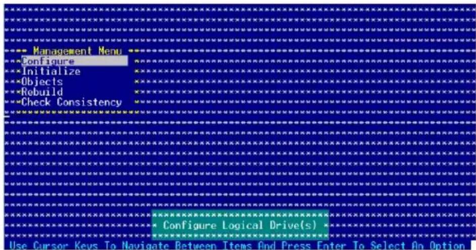
| Menu Description | Description |
| Configure Allows you to create RAID 0 or RAID 1 set using the EasyConfiguration or the New Configuration command. This menu also allows you to view, add, or clear RAID configurations or select the boot drive | |
| Initialize Allows you to initialize the logical drives of a created RAID set | |
| Objects Allows you to initialize logical drives or change the logical drive parameters | |
| Rebuild Allows you to rebuild failed drives | |
| Check Consistency Allows you to check the data consistency of the logical drives of a created RAID set | |
6.3.11 CreatingiaRAIDsetD set
The LSI Logic Embedded SATA RAID Setup Utility allows you to create a RAID 0 or RAID 1 set using two types of configurations: Easy and New.
In Easy Configuration, the logical drive parameters are set automatically including the size and stripe size (RAID 1 only).
In New Configuration, you manually set the logical drive parameters and assign the set size and stripe size (RAID 1 only).
Using Easy Configuration
To create a RAID set using the Easy Configuration option:
- From the utility main menu, highlight Configure, then press
. - Use the arrow keys to select Easy Configuration, then press
.
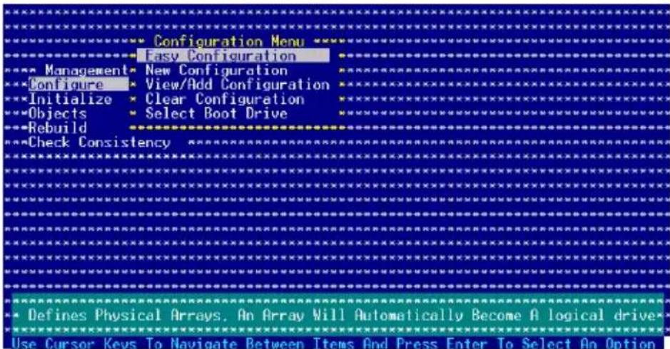
- The ARRAY SELECTION MENU displays the available drives connected to the SATA ports. Select the drives you want to include in the RAID set, then press
. When selected, the drive indicator changes from READY to ONLINE A[X]-[Y], where X is the array number, and Y is the drive number.
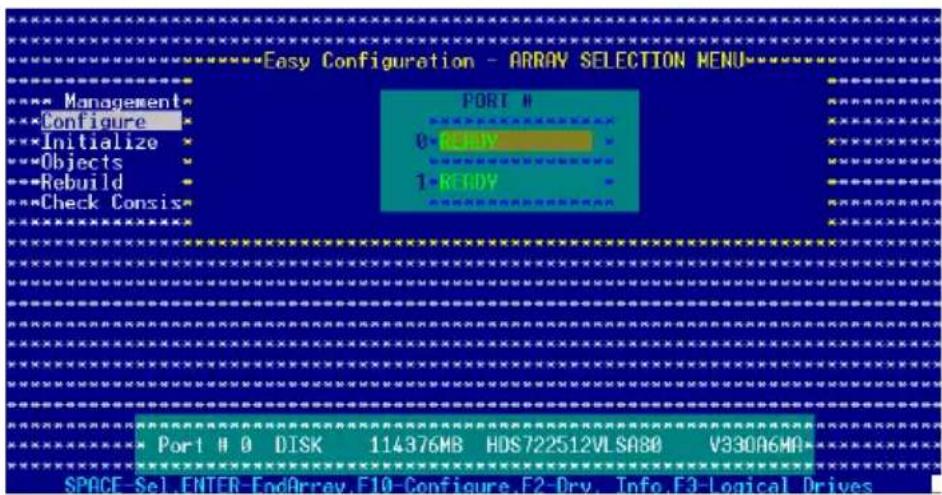

The information of the selected hard disk drive displays at the bottom of the screen.
- Select all the drives required for the RAID set, then press
. The configurable array appears on screen.
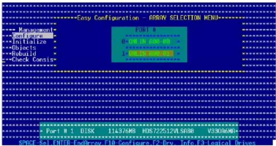
- Press
, select the configurable array, then press .
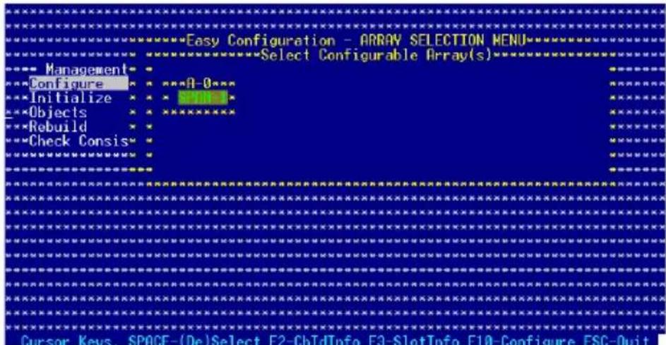
The logical drive information appears including a Logical Drive menu that allows you to change the logical drive parameters.
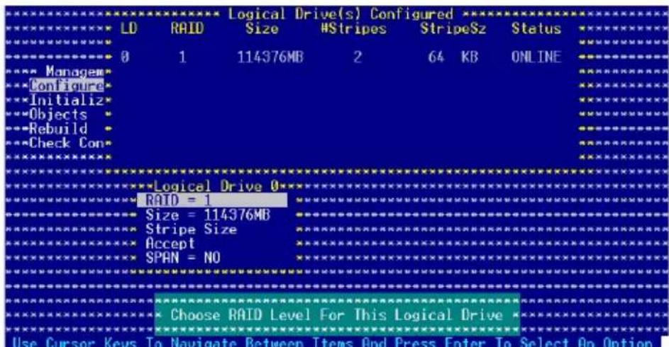
- Select RAID from the Logical Drive menu, then press
. - Select the RAID level from the menu, then press
.

You need at least two identical hard disk drives when creating a RAID 1 set.
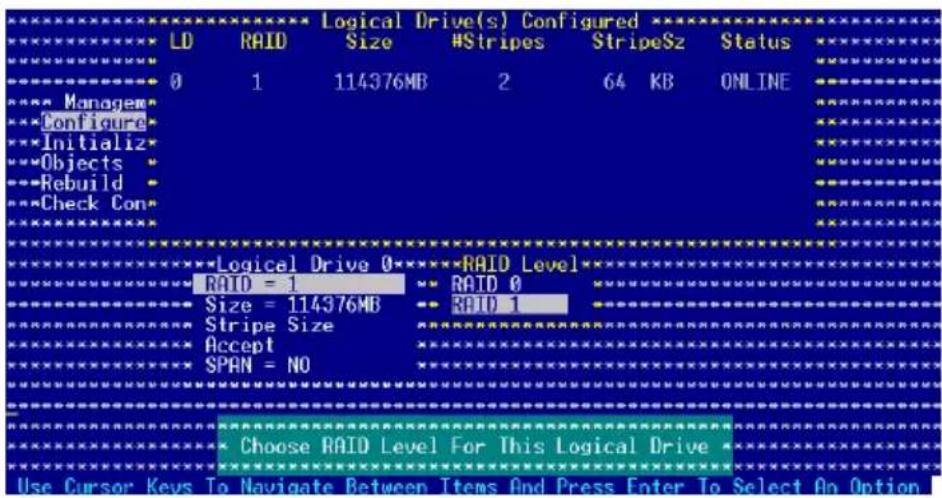
- When creating a RAID 1 set, select Stripe Size from the Logical Drive menu, then press
.
When creating a RAID 0 set, proceed to step 10.
- Key in the stripe size, then press
.
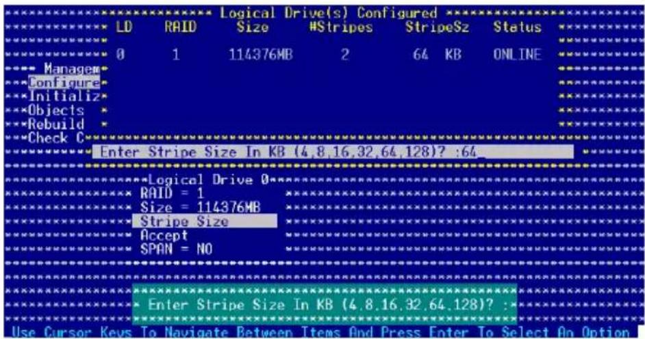

For server systems, we recommend that you use a lower array block size. For multimedia computer systems used mainly for audio and video editing, we recommend a higher array block size for optimum performance.
- When finished setting the selected logical drive configuration, select Accept from the menu, then press
.
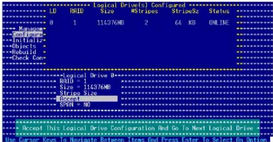
- Follow steps 5 to 10 to configure additional logical drives.
- When prompted, save the configuration, then press
to return to the Management Menu.
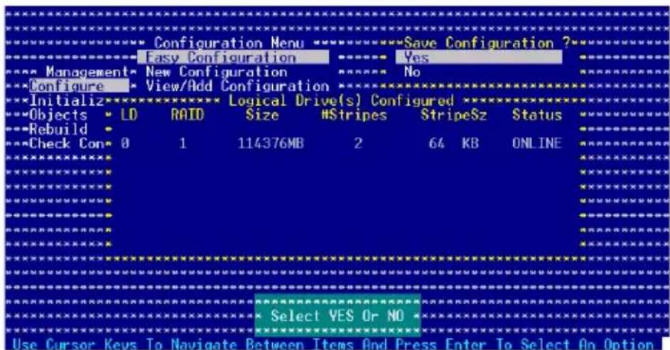
Using New Configuration

When a RAID set is already existing, using the New Configuration command erases the existing RAID configuration data. If you do not want to delete the existing RAID set, use the View/Add Configuration command to view or create another RAID configuration.
To create a RAID set using the New Configuration option:
- From the utility main menu, highlight Configure, then press
. - Use the arrow keys to select New Configuration, then press
.
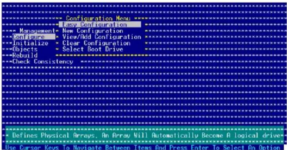
- Follow steps 3 to 7 of the previous section.
- Select Size from the Logical Drive menu, then press
. - Key in the desired logical drive size, then press
.
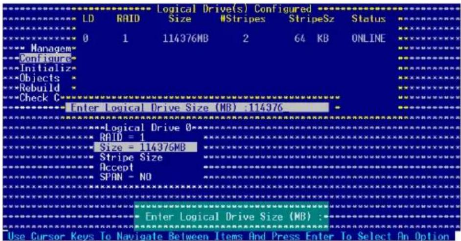
- Follow steps 8 to 12 of the previous section to create the RAID set.
6.3.22 Adding or viewing a RAID configuration
You can add a new RAID configuration or view an existing configuration using the View/Add Configuration command.
Adding a new RAID configuration
To add a new RAID configuration:
- From the Management Menu, highlight Configure, then press
. - Use the arrow keys to select View/AddConfiguration, then press
.
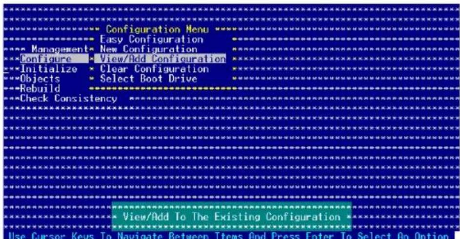
- The ARRAY SELECTION MENU displays the available drives connected to the SATA ports. Select the drive(s) you want to include in the RAID set, then press
. When selected, the drive indicator changes from READY to ONLINE[A][X][Y], where X is the array number, and Y is the drive number.
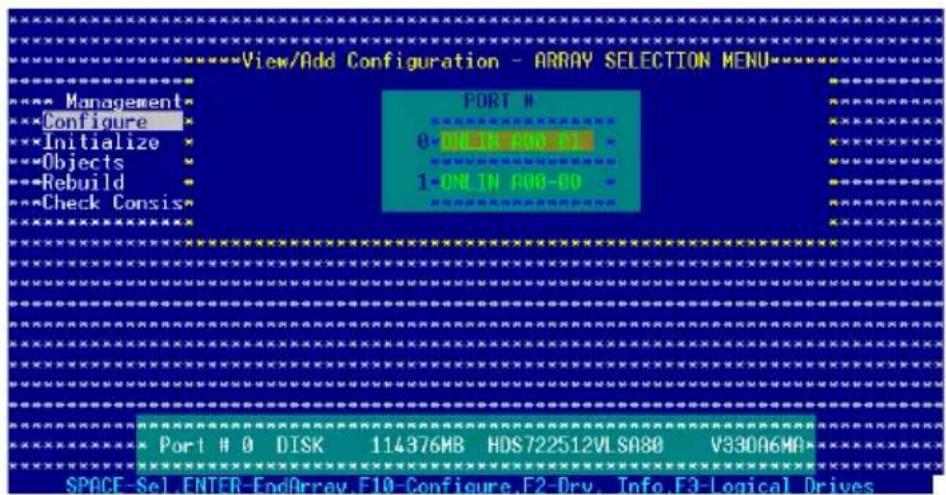

The information of the selected hard disk drive displays at the bottom of the screen.
- Select all the drives required for the RAID set, then press
. The configurable array appears on screen.
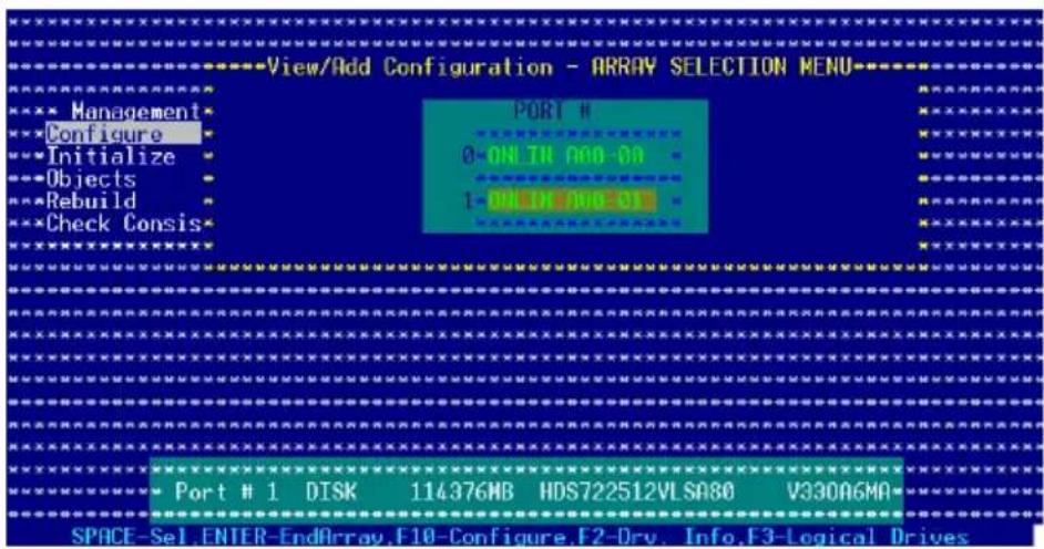
- Press
, select the configurable array, then press .
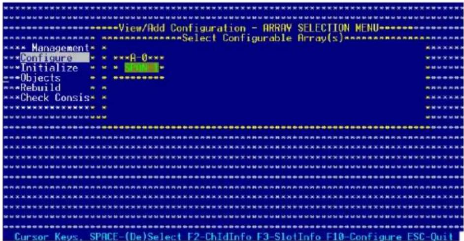
The logical drive information appears including a Logical Drive menu that allows you to change the logical drive parameters.
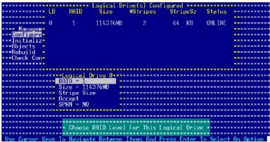
- Follow steps 6 to 7 of the Creating a RAID set: Using Easy Configuration section.
- Select Size from the Logical Drive menu, then press
. - Key in the desired logical drive size, then press
.
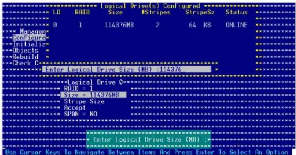
- Follow steps 8 to 12 of the Creating RAID set Using Easy Configuration section to add the new RAID configuration.
6.3.33 Initializing the logical drivesl drives
After creating the RAID set(s), you must initialize the logical drives. You may initialize the logical drives of a RAID set(s) using the Initialize or Objects command in the Management Menu.
Using the initialize command and
To initialize the logical drive using the Initialize command:
- From the Management Menu, highlight Initialize, then press
.
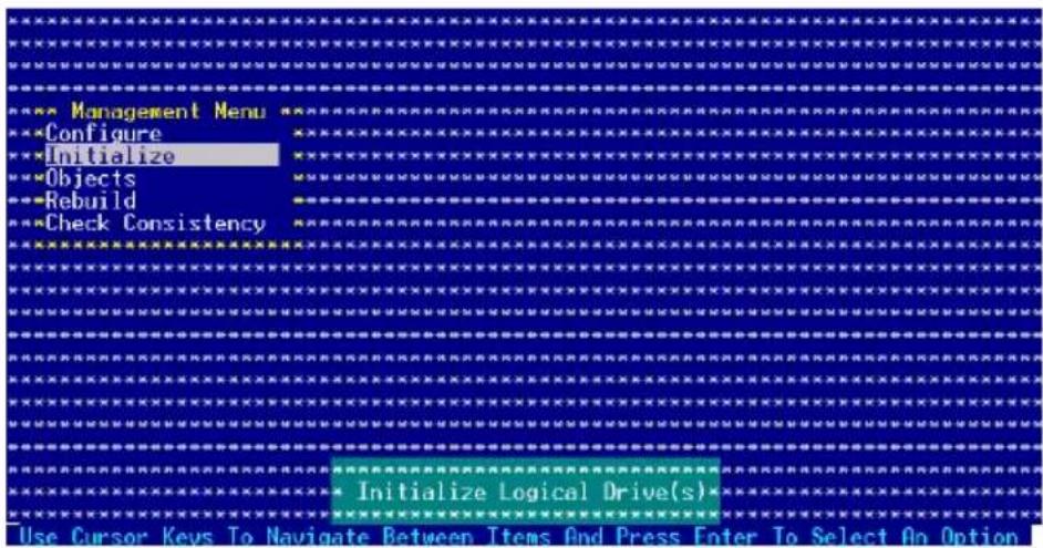
- The screen displays the available RAID set(s) and prompts you to select the logical drive to initialize. Use the arrow keys to select the logical drive from the Logical Drive selection, then press
.
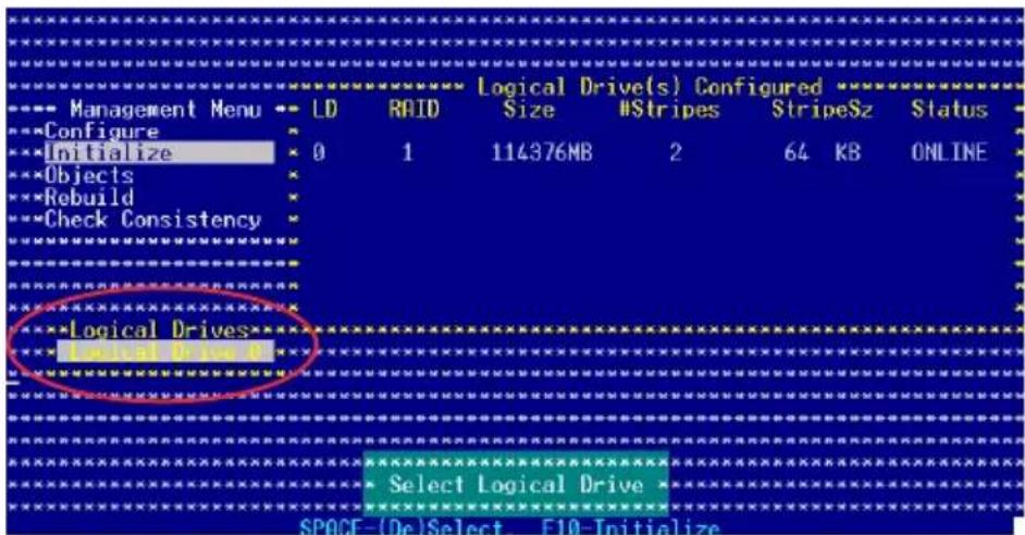
- When prompted, press the
to select Yes from the Initialize? dialog box, then press . You may also press to initialize the drive without confirmation.
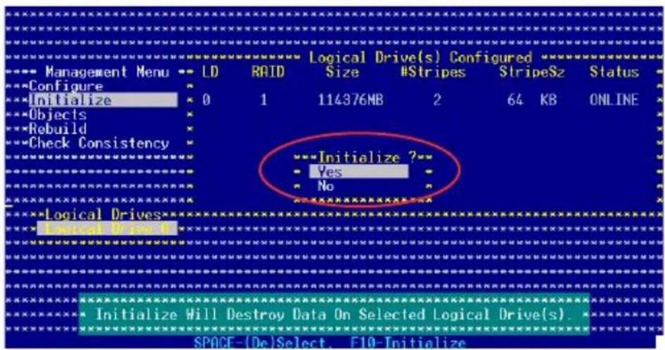

Initializing a logical drive(s) erases all data on the drive.
- A progress bar appears on screen. If desired, press
to abort initialization.
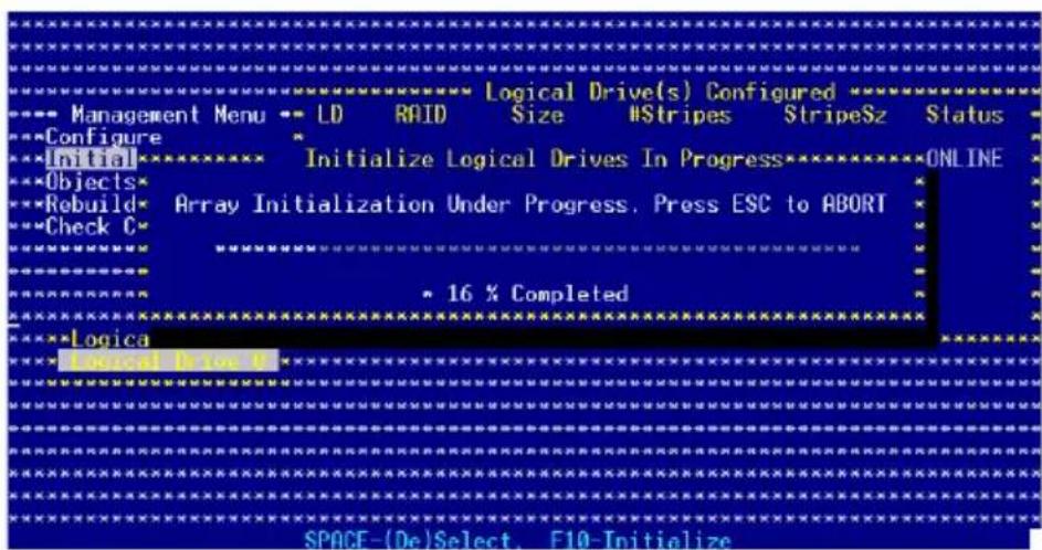
- When initialization is completed, press
.
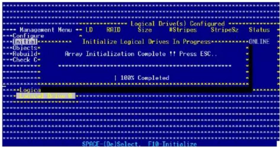
Using the Objects command and
To initialize the logical drives using the Objects command:
- From the Management Menu, highlight Objects, then press
.
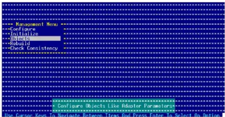
- Select Logical Drive from the Objects sub-menu, then press
.
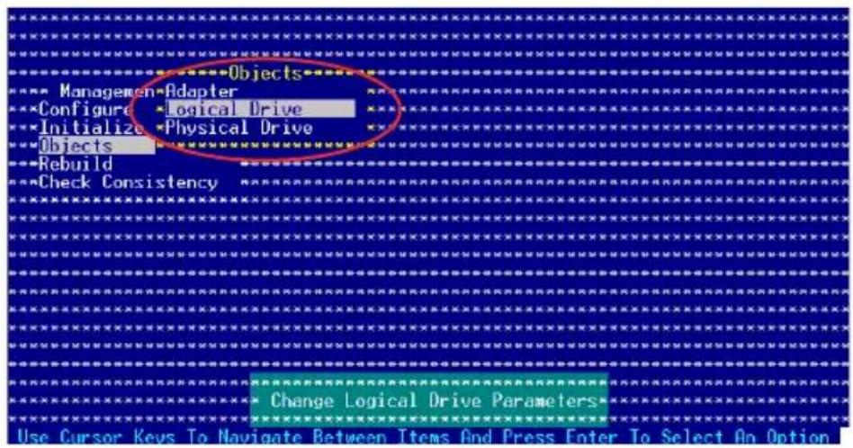
- Select the logical drive to initialize from the Logical Drives sub-menu, then press
.
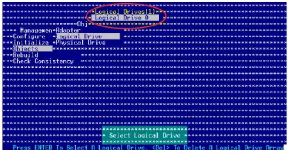
- Select Initialize from the pop-up menu, then press
to start initialization.
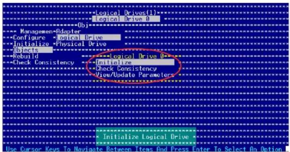
- When prompted, press the
to select Yes from the Initialize? dialog box, then press . You may also press to initialize the drive without confirmation.
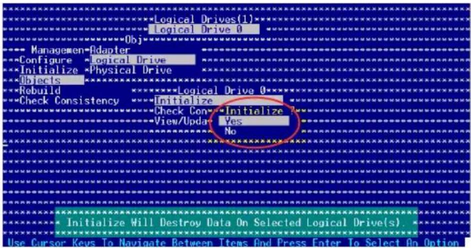
- A progress bar appears on screen. If desired, press
to abort initialization.
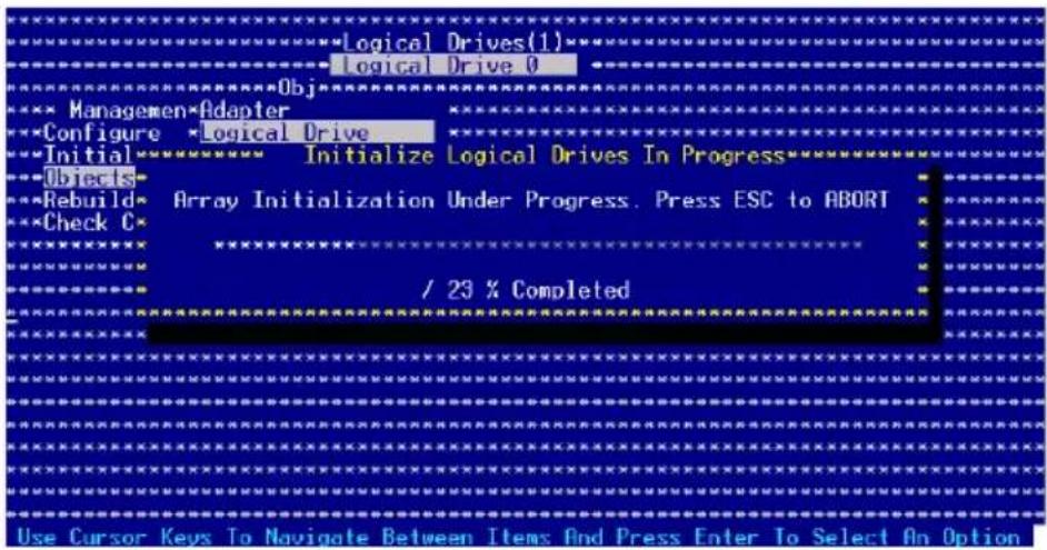
- When initialization is completed, press
.
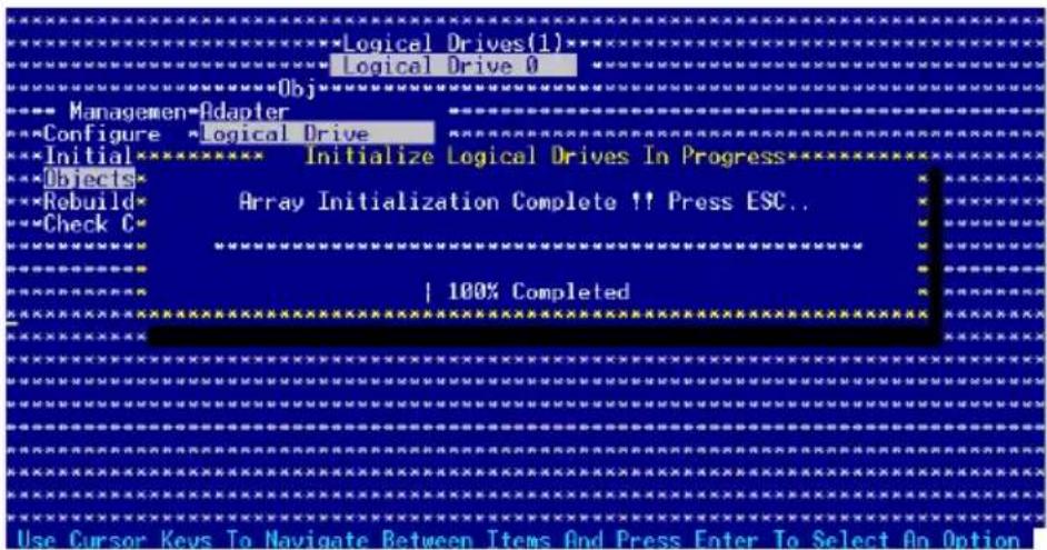
6.3.4 Rebuilding failed drives
You can manually rebuild failed hard disk drives using the Rebuild or Objects command in the Management Menu.
Using the Rebuild Command and
To rebuild a failed hard disk drive using the Rebuild command:
- From the Management Menu, highlight Rebuild then press
.
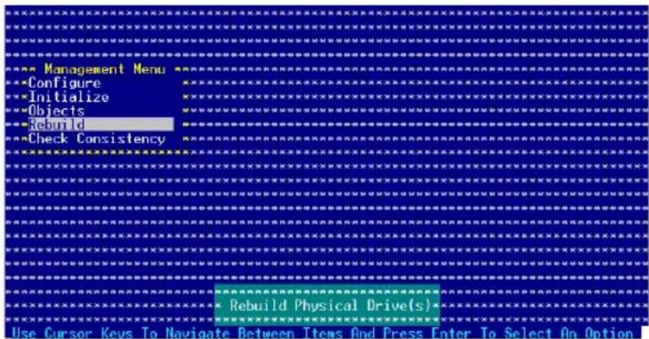
- The PHYSICAL DRIME SELECTION MENU displays the available drives connected to the SATA ports. Select the drive you want to rebuild, then press
.
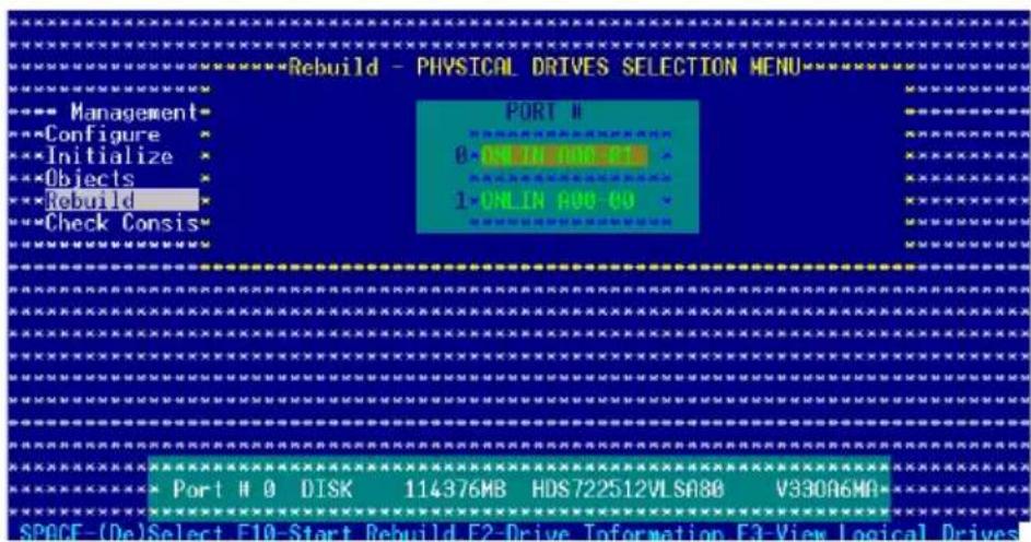
- After selecting the drive to rebuild, press
. The indicator for the selected drive now shows RBLD.
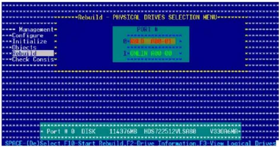
- When prompted, press
to rebuild the drive.
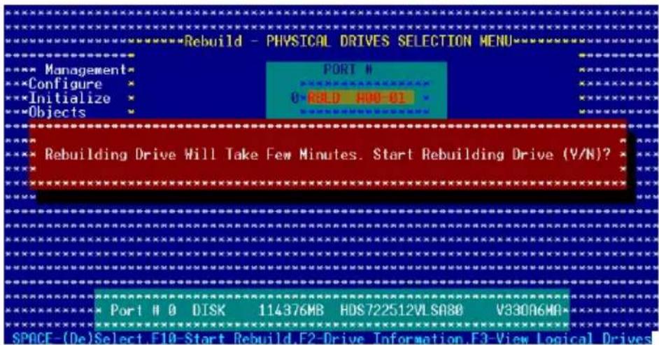
- When rebuild is complete, press any key to continue.
Using the Objects command and
To rebuild a failed hard disk drive using the Objects command:
- From the Management Menu, select Objects, then select Physical Drive from the menu.
- Use the arrow keys to select the physical drive you want to rebuild, then press
. - Select Rebuild from the pop-up menu, then press
. - When prompted, press
to to rebuild the drive. - When rebuild is complete, press any key to continue.
6.3.55 Checkingthe drives for data consistency
You can check and verify the accuracy of data redundancy in the selected logical drive. The utility can automatically detect and/or detect and correct any differences in data redundancy depending on the selected option in the Objects > Adapter menu.

The Check Consistency command is available only for logical drives included in a RAID 1 set.
Using the Check Consistency
To check data consistency using the Check Consistency command:
- From the Management Menu, select Check Consistency, then press
.
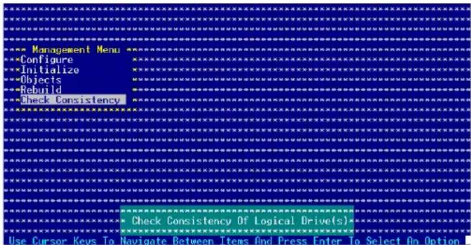
- The screen displays the available RAID set(s) and prompts you to select the logical drive to check. Use the arrow keys to select the logical drive from the Logical Drive selection, then press
.
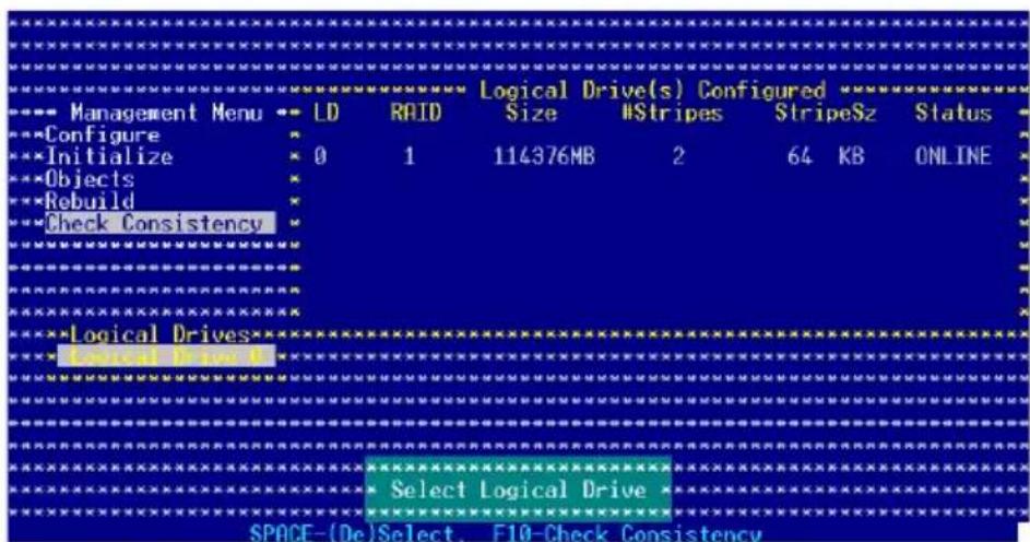
- When prompted, press the
to select Yes from the Consistency Check dialog box, then press . You may also press to check the drive consistency.
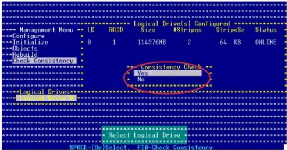
A progress bar appears on screen.
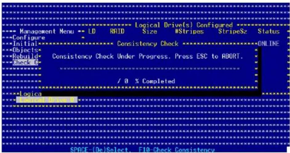
-
While checking the disk consistency, press
to display the following options. -
Stop - Stops the consistency check. The utility stores the percentage of disk checked. When you restart checking, it continues from the last percentage completed rather than from zero percent.
- Continue - Continues the consistency check.
-
Abort - Aborts the consistency check. When you restart checking, it continues from zero percent.
-
When checking is complete, press any key to continue.
Using the Objects command and
To check data consistency using the Objects command:
- From the Management Menu, select Objects, then select Logical Drive from the menu.
- Use the arrow keys to select the logical drive you want to check, then press
. - Select Check Consistency from the pop-up menu, then press
. - When prompted, press
to check the drive. - When checking is complete, press any key to continue.
6.3.66 Deletingia RAID configuration
To delete a RAID configuration:
- From the Management Menu, select Configurer ClearConfiguration then press
.
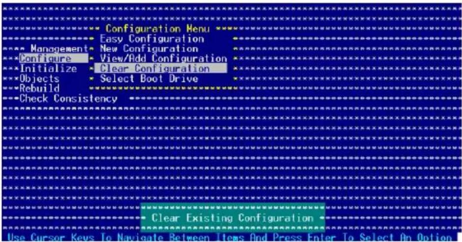
- When prompted, press the
to select Yes from the Clear Configuration? dialog box, then press .
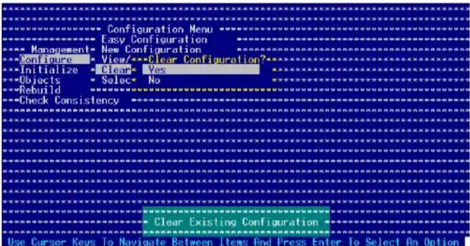
The utility clears the current array.
- Press any key to continue.
6.3.7 Selecting the boot drive from a RAID set RAID set
You must have created a new RAID configuration before you can select the boot drive from a RAID set. Refer to the Creating a RAID set: Using New Configuration section for details.
To select the boot drive from a RAID set:
- From the Management Menu, select Configur> Select Boot Drive, then press
.
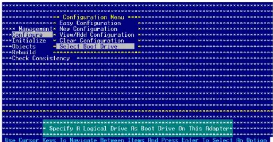
- When prompted, press the
to select the bootable logical drive from the list, then press .
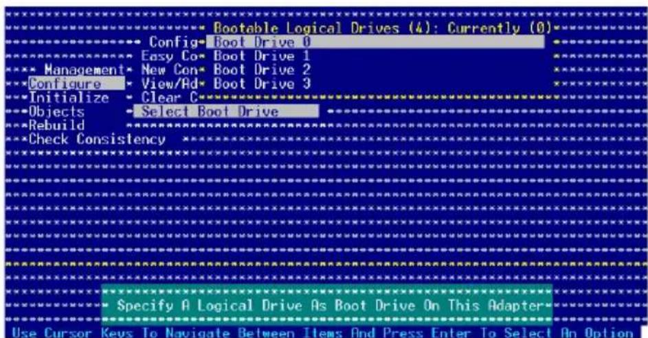
- The logical drive is selected as boot drive. Press any key to continue.
6.3.88 Enabling the WriteCache Cache
You may enable the RAID controller's WriteCache option to improve the data transmission performance.

When you enable WriteCache, you may lose data when a power interruption occurs while transmitting or exchanging data among the drives.
To enable WriteCache:
- From the Management Menu, select Objects > Adapter, then press
to display the adapter properties. - Select WriteCache, then press
to turn the option On (enabled).
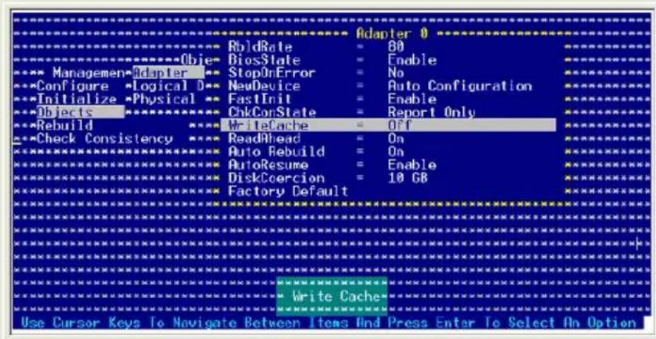
- When finished, press any key to continue.
6.4 Global Array Manager
You may also create a RAID set(s) in Windows® operating environment using the Global Array Manager (GAM) application. The GAM application is available from the motherboard support CD.

Refer to the GAM user guide in the motherboard support CD for details.
Chapter 7
This chapter provides instructions for installing the necessary drivers for different system components.
Driver insaltation
7.1 RAID driver installation
After creating the RAID sets for your server system, you are now ready to install an operating system to the independent hard disk drive or bootable array. This part provides instructions on how to install the RAID controller drivers during OS installation.
7.1.1 Creating a RAID driver disk

You may have to use another system to create the RAID driver disk from the system/motherboard support CD or from the Internet.
A floppy disk with the RAID driver is required when installing Windows ^® 2000 or Red Hat ^® Enterprise ver. 3.0/SuSE operating system on a hard disk drive that is included in a RAID set. You can create a RAID driver disk in DOS (using the Makedisk application in the support CD).
To create a RAID driver disk in DOS environment:
- Place the motherboard support CD in the optical drive.
- Restart the computer, then enter the BIOS Setup.
- Select the optical drive as the first boot priority to boot from the support CD. Save your changes, then exit the BIOS Setup.
- Restart the computer.
- Press any key when prompted to boot from CD.
Loading FreeDOS FAT KERNEL GO!
Press any key to boot from CDROM...
The Makedisk menu appears.
A) FreeDOS command prompt
B) Make Intel ICH7R LSI MegaRAID for Win32/64 bit driver disk
C) Make Intel ICH7R LSI MegaRAID for RHEL 3 32/64 bit driver disk
D) Make Intel ICH7R LSI MegaRAID for RHEL 4 32/64 bit driver disk
E) Flash AMI BIOS for RS100-E4/PI2
F) Broadcom ASF Firmware Update
G) Write RS100-E4/PI2 FRU
Please choose A To G:
- Place a blank, high-density floppy disk to the floppy disk drive, then select the type of RAID driver disk you want to create by typing the number before the option
- Press
. - Follow screen instructions to create the driver disk.
7.1.2 Installing the RAID controller driver
Windows® 2000/2003 Server OS
During Windows® 2000/2003 Server OS installation
To install the RAID controller driver when installing Windows® 2000/2003 Server OS:
- Boot the computer using the Windows ^® 2000/2003 Server installation CD. The Windows ^® 2000/2003 Setup starts.
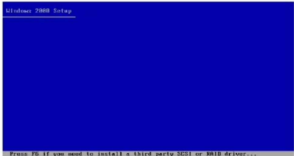
- Press
when the message "Press F6 if you need to install third party SCSI or RAID driver..." appears at the bottom of the screen. - When prompted, press
to specify an additional device.
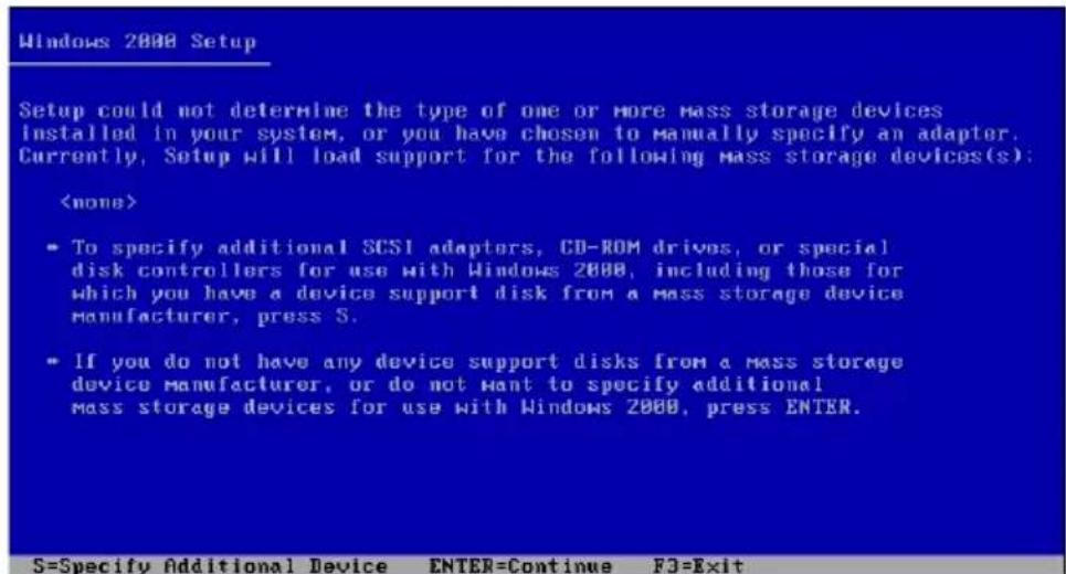
- Insert the RAID driver disk you created earlier to the floppy disk drive, then press
.
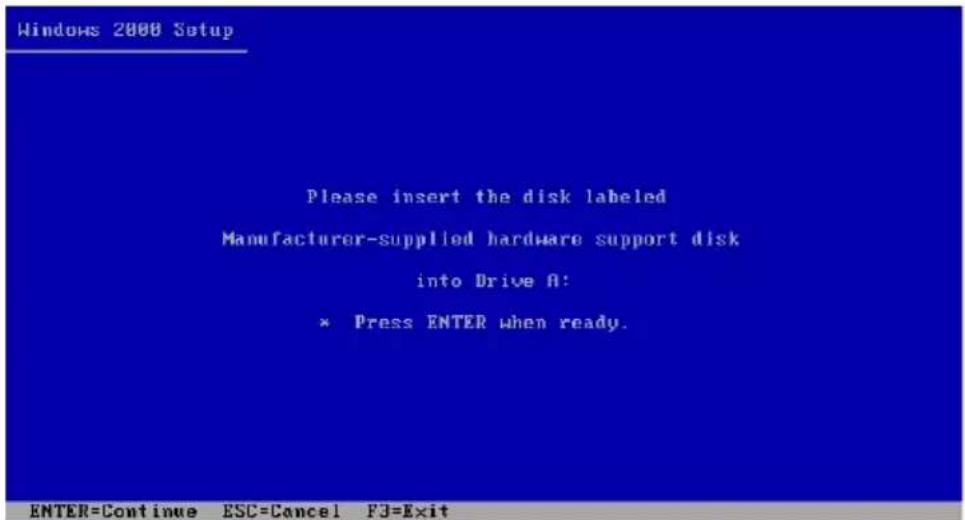
- Select the RAID controller driver from the list, then press
.
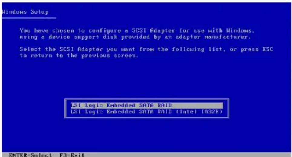
LSII Logici SATATRAIDA ID
Select "LSI Logic Embedded SATA RAID" for Windows 2000 or 32bit Windows 2003 Server OS from the list, then press
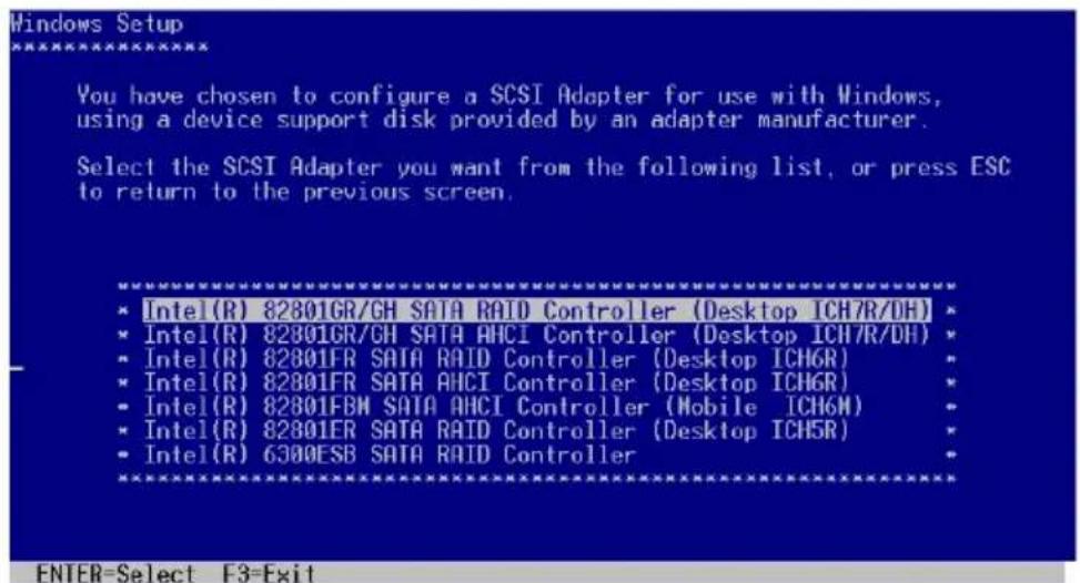
Intel Matrix Storage
Select "Intel(R) 82801GR/GH SATA RAID Contributor (Desktop CHTRD)" for Intel Matrix Storage RAID mode from the list, then press
If you configured SATA as AHCI Mode in the BIOS setup utility of IDE Configuration, first install the Intel SATA AHCI Driver during windows setup. Then, select the "Intel(R) 82801GR/GH SATA AHCHorController (Desktop ICH7RDH)" from the list. Refer to section "7.1.1 Creating a RAID driver disk" to create the Intel SATA Driver for windows system.
- The Windows ^® 2000/2003 Setup loads the RAID controller drivers from the RAID driver disk. When prompted, press
to continue installation. - Setup then proceeds with the OS installation. Follow screen instructions to continue.
To an existing Windows® 2000/2003 Server OS
To install the RAID controller driver on an existing Windows ^®
2000/2003 Server OS:
- Restart the computer, then log in with Administrator privileges.
- Windows ^ automatically detects the RAID controller and displays a New Hardware Found window. Click Cancel.
- Right-click the My Computer icon on the Windows ^ desktop, then select Properties from the menu.
- Click the Hardware tab then click the Device Manager button to display the list of devices installed in the system.
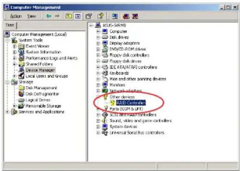
- Right-click the RAID controller item, then select Properties
- Click the Driver tab, then click the Update Driver button.
- The Upgrade Device Driver Wizard window appears. Click Next
- Insert the RAID driver disk you created earlier to the floppy disk drive.
- Select the option "Search force suitable driver for my device (recommended)", then click Next.
- The wizard searches the RAID controller drivers. When found, click Next to install the drivers.
- Click Finish after the driver installation is done.
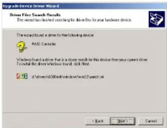
To verify the RAID controller driver installation:
- Right-click the My Computer icon on the Windows ^ desktop, then select Properties from the menu.
- Click the Hardware tab, then click the Device Manager button.
- Click the “+” sign before the item SCSI and RAID controllers: The L SUS Logic Embedded SATA RAID or Intel® 8201 GR/GH SATA RAID items should appear.
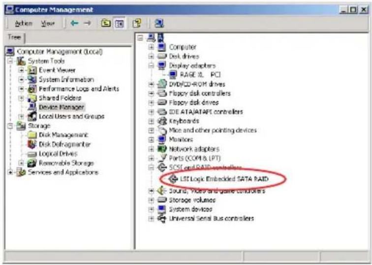
- Right-click the RAID controlled driver item, then select Properties from the menu.
- Click the Driver tab, then click the Driver Details button to display the RAID controller drivers.
- Click OK when finished.
Red Hat® Enterprise ver. 3.0
To install the Intel® ICH7R LSI Logic Embedded SATA RAID controller driver when installing Red Hat® Enterprise ver. 3.0 operating system:
- Boot the system from the Red Hat ^® Installation CD.

Red Hat Enterprise Linux
![- To install or upgrade in graphical node, press the key. - To install or upgrade in text node, type: linux text . - Use the function keys listed below for more information. [F1-Main] [F2-Options] [F3-General] [F4-Kernel] [F5-Rescue] boot: _](/content/2026/06/1196266/images/06303e6b385c8f2725f8f83f895347507b8b6215c781ce3ba5126a7af8ea190c.jpg)
- At the boot:, type linux dd, then press
.
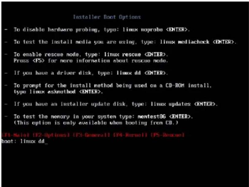
- Select Yes using the
key when asked if you have the driver disk. Press
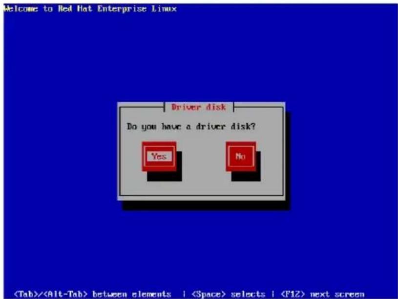
- Select fdQ using the
key when asked to select the driver disk source. Press to move the cursor to OK, then press .
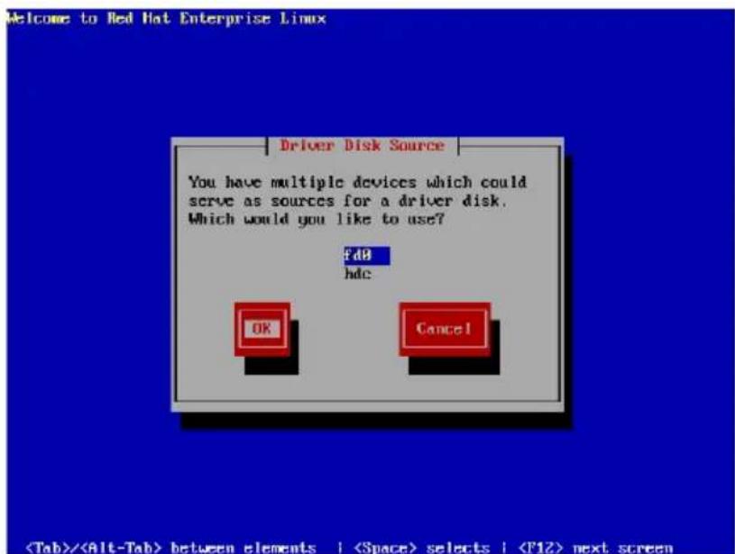
- When prompted, insert the Red Hat ^ Enterprise ver. 3.0 RAID driver disk to the floppy disk drive, select OK, then press
.
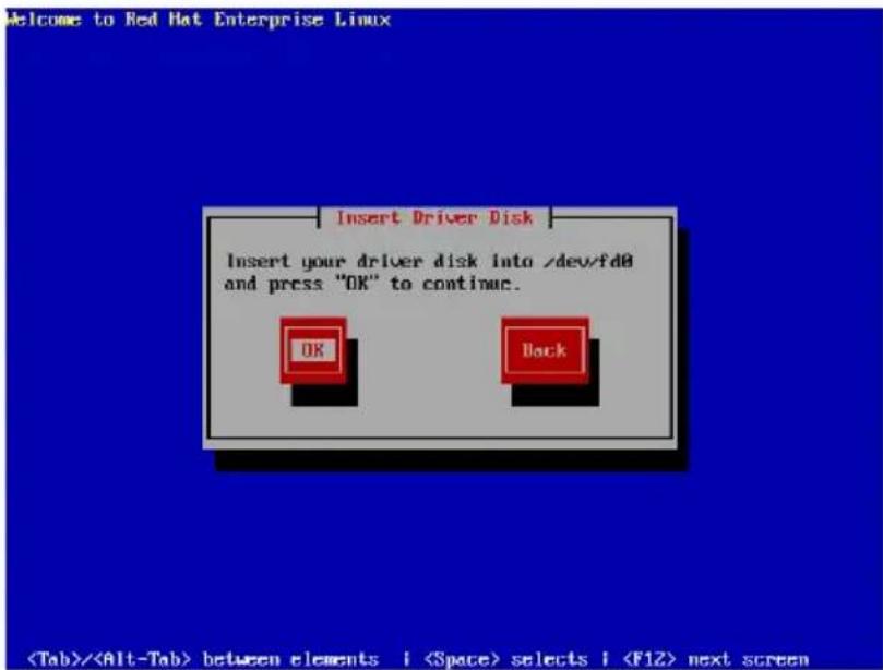
The drivers for the RAID controller are installed to the system.
- When asked if you will load additional RAID controller drivers, select Yes, then install the additional RAID controller drivers.
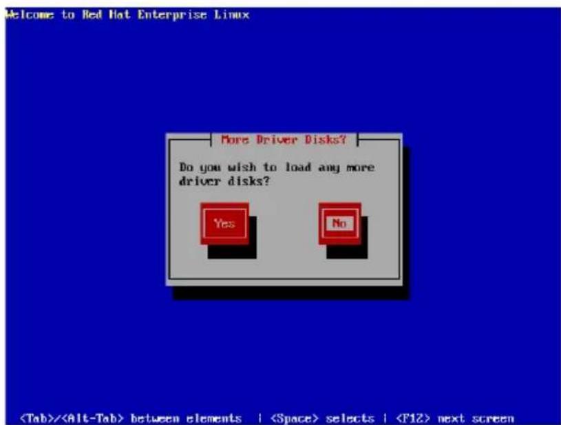
- Follow screen instructions to continue the OS installation.
SuSE Linux
To install the RAID controller driver when installing SuSE Linux OS:
- Boot the system from the SuSE Installation CD.
- Select Installation from the Boot Options menu, then press
.
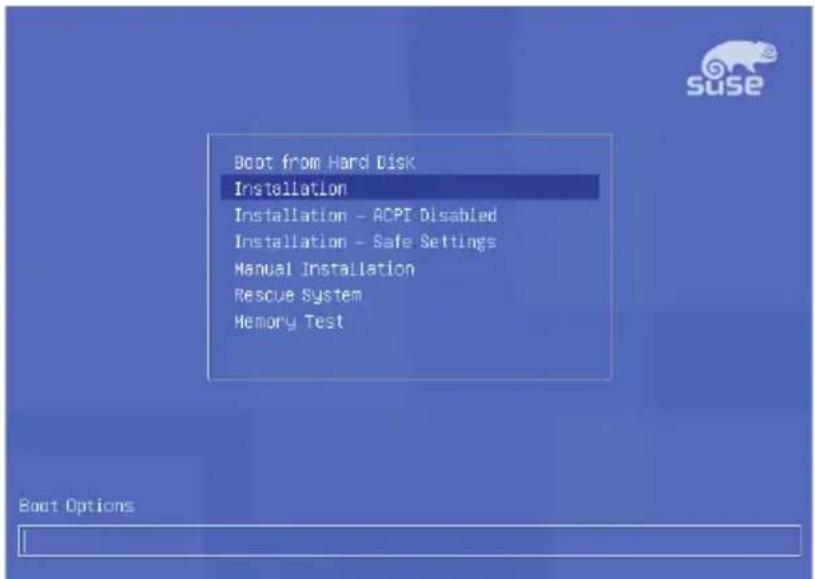
F1 Help F2 800 x 600 F3 CD-ROM F4 English F5 Sllent F6 Driver Update
- A message instructs you to prepare the RAID driver disk. Press
.
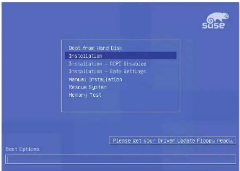
F1 Help F2 800 x 600 F3 CD-ROM F4 English F5 Silent F6 Driver Update

For SuSE Linux Enterprise Server 9.0 SP1 operating system, do not use OS bundled driver, otherwise your computer may become unstable due to OS limitation.
- When prompted, insert the RAID driver disk to the floppy disk drive, then press
.
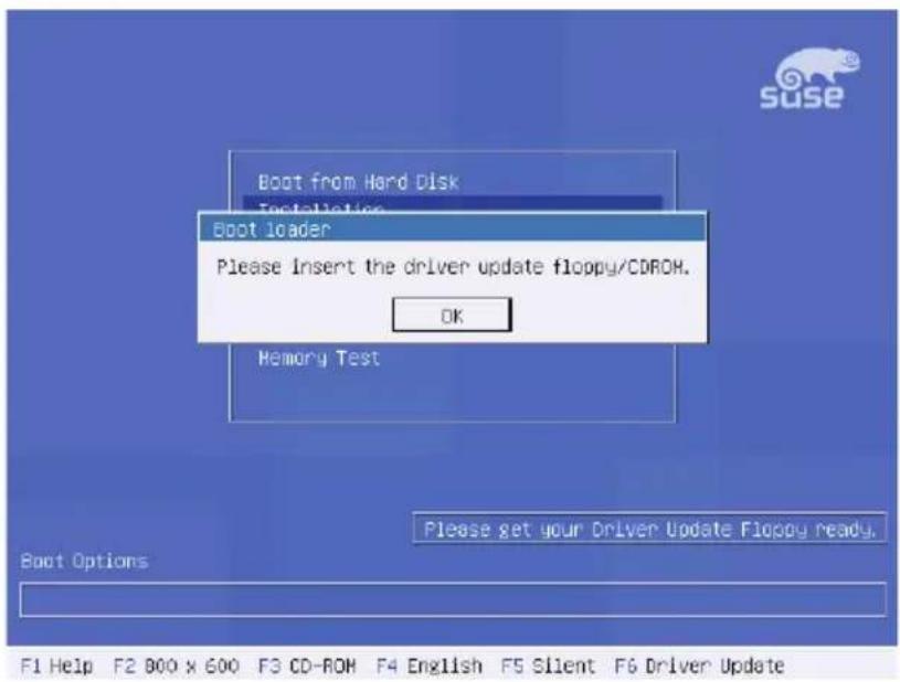
- When prompted, select the floppy disk drive (fd0) as the driver update medium, select OK, then press
.
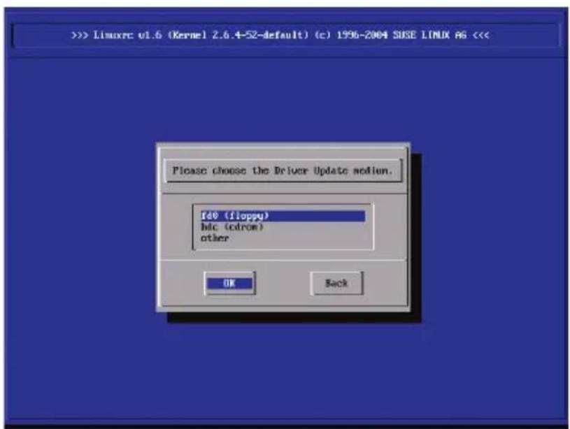
The drivers for the RAID controller are installed to the system.
7.2 LAN driver installation
This section provides instructions on how to install the Broadcom® Gigabit LAN controller drivers.
7.2.1 Windows ^® 2000/2003 Server
To install the Broadcom® Gigabit LAN controller driver on a Windows® 2000/2003 Server OS:
- Restart the computer, then log on with Administrator privileges.
- Insert the motherboard/system support CD to the optical drive. The CD automatically displays the Drivers menu if Autorun is enabled in your computer.

- Windows ^® automatically detects the LAN controllers and displays a New Hardware Found window. Click Cancel to close this window.
-
If Autorun is NOT enabled in your computer, browse the contents of the support CD to locate the file ASSETUP.EXE from the BIN folder. Double-click the ASSETUP.EXE to run the CD.
-
Click the Broadcom 5721 Drive option to begin installation.
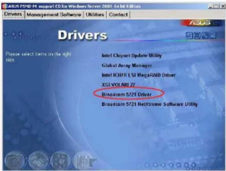
- Click Next when the InstallShield Wizard window appears. Follow screen instructions to continue installation.
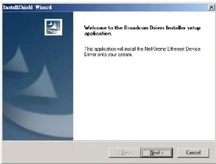
7.2.2 Red Hat ® Enterprise ver. 3.0
Follow these instructions when installing the Broadcom® Gigabit LAN controller base driver for the Red Hat® Enterprise ver. 3.0 operating system.
Building the driver from the TAR file

Install first the Kernel Development tools before building the driver from the TAR file.
To build the driver from the TAR file:
- Create a directory and extract the TAR files: tar xvzf bcm5700-
.tar.gz - Build the driver bcm5700.o as a loadable module for the running kernel: cd bcm5700-
/src make - Test the driver by loading it: insmod bcm5700.o
- Install the driver and man page: make install
- Refer to Red Hat distribution documentation to configure the network protocol and address.
7.3 VGA driver installation
This section provides instructions on how to install the XGI Graphics driver.
7.3.1 Windows ^® 2000 Server
You need to manually install the XGI Graphics driver on a Windows® 2000 Server operating system.
To install the XGI Graphicsdriver:
- Restart the computer, then log on with Administrator privileges.
- Insert the motherboard/system support CD to the optical drive. The support CD automatically displays the Drivers menu if Autorun is enabled in your computer.

Windows® automatically detects the VGA controller and displays a New Hardware Found window. Click Cancel to close this window.
- Click the item XGFI VOLARI Z7 from the Drivers menu.
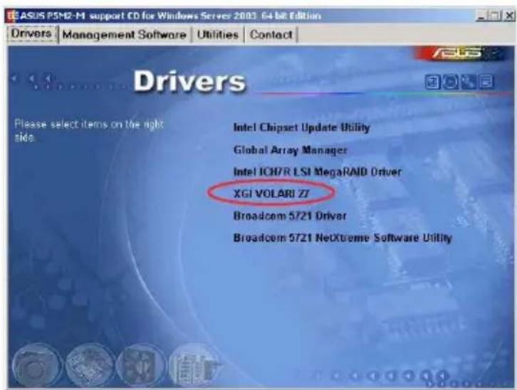
- The XGIVOLARIZ7 window appears. Click Next. Follow screen instructions to complete installation.
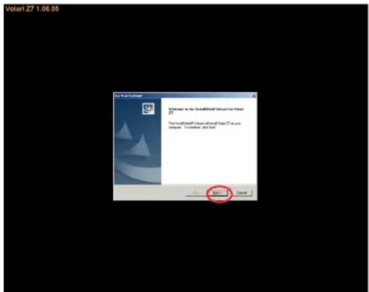

The VGA server does not obtain the authorization from Microsoft® WHQL 2000, but it supports Microsoft® Windows® 2000 Server.
7.3.2 Windows ^® 2003 Server
The Windows ^® 2003 Server operating system automatically recognizes the XGI Graphics driver during system installation. There is no need to install an additional driver(s) to support the onboard VGA.
7.3.3 Red Hat ^® Enterprise ver. 3.0
The Red Hat® Enterprise ver. 3.0 operating system automatically recognizes the XGI Graphics driver during system installation. There is no need to install an additional driver(s) to support the onboard VGA.
7.4 Management applications and utilities installation
The support CD that came with the motherboard package contains the drivers, management applications, and utilities that you can install to avail all motherboard features.

The contents of the support CD are subject to change at any time without notice. Visit the ASUS website (www.asus.com) for updates.
7.4.1 Running the support CD
Place the support CD to the optical drive. The CD automatically displays the Drivers menu if Autorun is enabled in your computer.

If Autorun is NOT enabled in your computer, browse the contents of the support CD to locate the file ASSETUP.EXE from the BIN folder. Double-click the ASSETUP.EXE to run the CD.
7.4.2 Drivers menu
The Drivers menu shows the available device drivers if the system detects installed devices. Install the necessary drivers to activate the devices.

The screen display and driver options vary under different operating system versions.
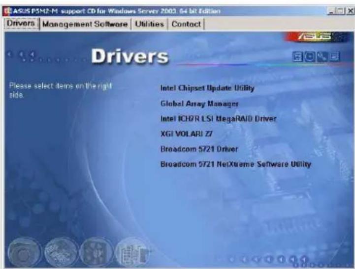
7.4.3 Management Software menu
The Management Software menu displays the available network and server monitoring application. Click on an item to install.
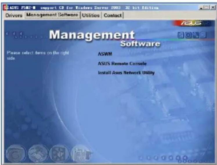
7.4.4 Utilities menu
The Utilities menu displays the software applications and utilities that the motherboard supports. Click on an item to install.
7.4.5 Contact information
Click the Contact tab to display the ASUS contact information. You can also find this information on the inside front cover of this user guide.
The Appendix describes the CPU features that the motherboard supports.
Reference information
A.1 Intel ^® EM64T

- The motherboard is fully compatible with Intel ^ Pentium ^ 4 LGA775 processors running on 32-bit operating systems.
- The motherboard comes with a BIOS file that supports EM64T. You can download the latest BIOS file from the ASUS website (www.asus.com/support/download/) if you need to update the BIOS file. See Chapter 5 for details.
- Visit www.intel.com for more information on the EM64T feature.
- Visit www.microsoft.com for more information on Windows® 64-bit OS.
Using the Intelte1® EM64Tfeature
To use the Intel ^® EM64T feature:
- Install an Intel ^ Pentium ^ 4 CPU that supports the Intel ^ EM64T.
- Install a 64-bit operating system (Windows ^ XP Professional x64 Edition).
- Install the 64-bit drivers for the motherboard components and devices from the support CD.
- Install the 64-bit drivers for expansion cards or add-on devices, if any.

Refer to the expansion card or add-on device(s) documentation, or visit the related website, to verify if the card/device supports a 64-bit system.
A.2 Enhanced Intel SpeedStep Technology (EIST)

- The motherboard comes with a BIOS file that supports EIST. You can download the latest BIOS file from the ASUS website (www.asus.com/support/download/) if you need to update the BIOS. See Chapter 5 for details.
- Visit www.intel.com for more information on the EIST feature.
A.1 System requirements
Before using EIST, check your system if it meets the following requirements:
- Intel ^ Pentium ^ 4 processor with EIST support
• BIOS file with EIST support - Operating system with EIST support (Windows ^ XP SP2/Linux 2.6 kernel or later versions)
A.2.2 Using the EISTEIST
To use the EIST feature:
-
Turn on the computer, then enter the BIOS Setup.
-
Go to the Advanced Menu, highlight CPU Configuration, then press
. -
Set the Intel(R) SpeedStep Technology item to [Automatic], then press
. See page 5-24 for details. -
Press
to save your changes and exit the BIOS setup. -
After the computer restarts, right click on a blank space on the desktop, then select Properties from the pop-up menu.
-
When the Display Properties window appears, click the Screen Saver tab.
-
Click the Power button on the Monitor power section to open the Power Options Properties window.
![Display Properties Themes Desktop Screen Screen Appearance Settings Screen cover [None] Settings Progress Start 10 minutes One minute, password protect Monitor cover To adjust monitor power settings and save energy. click Power. Power OK Cancel Apply](/content/2026/06/1196266/images/6018ca3c68b4d978ba4097ec805428d184c7a8cd8a2cb81b47e3df39afc8e29e.jpg)
-
On the Power schemes section, click ▼, then select any option except Home/Office Desktop or Always On.
-
Click Apply, then click OK.
-
Close the Display Properties window.
After you adjust the power scheme, the CPU internal frequency slightly decreases when the CPU loading is low.
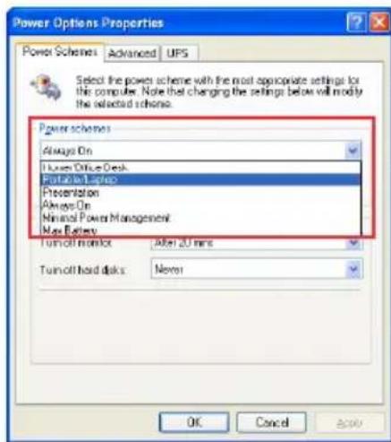

The screen displays and procedures may vary depending on the operating system.
- Contents
- Chapter 1: Product introduction
- Chapter 2: Hardware setup
- Chapter 3: Installation options
- Chapter 4: Motherboard Info
- Chapter 5: BIOS Setup
- Advanced menu 5-19
- Power Configuration.... 5-28
- Boot menu 5-31
- Exit menu 5-37
- Chapter 6: RAID Configuration
- RAID configurations 6-2
- Intel ® Matrix Storage Manager Option ROM Utility 6-4
- LSI Logic Embedded SATA RAID Setup Utility 6-12
- Chapter 7: Driver installation
- Appendix
- Notices
- Federal Communications Commission Statement
- Canadian Department of Communications Statement
- Safety information
- Electrical Safety
- Operation Safety
- Lithium-Ion Battery Warning
- Heavy System
- About this guide
- Audience
- Conventions
- Typography
- References
- Chapter 1
- product integration
- System package contents
- System specifications
- Front panel features
- Rear panel features
- Internal features
- LED information
- Front panel LEDs
- Rear panel LEDs
- Chapter 2
- Hardware setup
- Chassis cover
- Removing the cover
- Installing the cover
- Motherboard information
- Central Processing Unit (CPU)
- Installing the CPU
- Installing the CPU heatsink
- System memory
- Overview
- Memory configurations
- Installing a DIMM
- To install a DIMM:
- Removing a DIMM
- Replaceable components
- Installing the system blower
- Installing Serial ATA drives
- To install secondary Serial ATA drive:
- Installing optical disk drive (ODD)
- Chapter 3
- installation options
- Rackmount rail kit items
- Attaching the rack ears
- Attaching the rails to the rack
- Chapter 4
- Mothereboar info
- Motherboard overview
- Layoutcontents
- Jumpers
- Clear RTCRAM(CLRTC1)TC1)
- To erase the RTC RAM:
- CRUP fan pin selection (6-pin FM\_pCPUAMEPCPU2FM\_CPU2)
- Keyboard/Mouse power (3-pin(KBPWR1)BPWR1)
- VGA controller setting (8-pin VGA\_iEN1GA\_EN1)
- GigabitLAN\_controllersetting [3-pimgLAN-EN1LLAN\_EN2) LAN\_EN2)
- RAIDController selection(3-ipin RAIDjSERAD\_SEL1)
- Force BIOS recovery setting (Step RECOVERY RECOVERY1)
- Connectors
- Rear panel connectors
- Internal connectors
- FI6bpydjskdrivelconnection(34-drp(nFLOPPY1)FLOPPY1)
- ICH7R primary IDE do Electron(40-1rp(nPRILIDE1)PRI\_IDE1)
- SerialATA Connectors(7-pin (SATA1, SATA2,, SATA3,2, SATA3, SATA4))
- Important notes on Serial ATA
- Hard disk activity of LED chellectron (4-pin HDLED1r) HDLED1
- Serial port connector(10-1 pinCOM2) COM2)
- CPU and system fan connectors sectors
- (3-pinCPULFAN1,NCPUCFAN2)
- Backplane SMBus Connection (6-10 pin BPSMB1)BPSMB1
- Power supply SMBus connector(5-pin PSUSMB1)PSUSMB1)
- SSIppwereconnectors (24-pin ATXPWRX, 8-pin ATX1i2V2TX12V2)
- Auxiliary papelconnectoe (20-pin2AUXiPANE1 PANEL1)
- Systempanel connector(20-pin PANEL PANEL 1)
- Chapter 5
- BIOS setup
- Managing and updating your BIOS
- Creating a bootable floppy disk py disk
- AFUPOSutility
- Copying the current BIOSIOS
- Updating the BIOS file file
- Updating the BIOS file linking a USB flash drive
- ASUS CrashFreeBIOS 2 utility utility
- Recovering the BIOS from a floppy disk
- Recovering the BIOS from the support CD port CD
- ASUS Update utility
- Installing ASUS Update
- Updating the BIOS through the Internet
- Updating the BIOS through a BIOS fileOS file
- BIOS setup program
- BIOS menu screen
- Menubarbar
- Navigation keyskeys
- Menuritems
- Sub-menuitemis ems
- Configuration fields fields
- Popup-window
- Scrollbar bar
- General help
- Main menu
- SystemTime[i:xx:x[xxx]xx:xx]
- System Date [Day[xx/xx/xxxx]/xxxx]
- Legacy Diskette A [Disabled]
- Primary Third, Fourth DE Master/Slave/Slave
- Type [Auto]
- LBA/Large Mode [Auto] to
- Block(Multi-sector Transfer)[Auto][Auto]
- PIO Model [A[uta]:o]
- DMA Model [A[uto] ]
- SMARTMonitoringi [Auto]
- 32BitDataTransfer[Enabled]
- IDE Configuration
- Configure SATATAs [Standard IDE]d IDE]
- Onboard IDE Operate Mode [Enhanced Mode]
- OnBoard Serial-ATA BOOTROM [Disabled]
- ALPE and ASP [Disabled]
- Stagger Spinup Support [Disabled]
- System Information
- AMI BIOS S
- Processor
- System Memory
- Advanced menu
- USB Configuration
- USB Function [4 [USB Ports]
- Legacy USB Support [Enabled]
- USB 2.0 Controller [Enabled]
- USB2.0 Controller mode [HiSpeed]
- BIOSSEIBICHand+Off[Enabled]
- MPS Configuration
- MPS Revision [1 [4].4]
- Remote Access Configuration
- Remote Access [Disabled] led]
- Serial port numberb[COM10M1]
- SerialPortMode[1520080n,1], n,1]
- FlowControl [None]
- Redirection After BIOS POST [Always]ways]
- TerminalType[ANSI]
- VT-UTF8ComboKeySupport[Enab[Ed]abled]
- Media Type [Serial]
- Trusted Computing
- CPU Configuration
- Max CPUID Value Limit [Disabled]
- Execute Disabled Function [Disabled]
- Enhanced C1Control[Auto]
- Virtualization Technology | [Enab[Ed]abled]
- CPU Internal Thermal Control [Autb] [Auto]
- Chipsets Configuration
- DRAMFFrequency [Auto]
- Configure DRAMTiming bySPD [Enabled]
- Spread Spectrum [Disabled]
- Onboard LAN Boot ROM [Enabled]
- PEG Port Configuration
- MemoryRenameFeature [Enabled]
- Onboard Devices Configuration
- Serial Port Address [3F8[/IRQ4]/IRQ4]
- Serial Port2Address [2F8/IRQ3]IRQ3]
- Parallel Port Address [378][378]
- Parallel Port Mode [ECP]
- PCPPhPNP
- BIOS SETUP UTILITY
- Advanced
- Plug And Play O/S [No[No]
- PCI Latency Timem[64][64]
- Allocate RQ to PCI VGA[Yes][Yes]
- Palette Snoopingi [Disabled]
- IRQ-xx assigned to [PCI[Device]
- Power Configuration
- ACPII APIO Supporto[Enabled]
- APM Configuration
- Restore on ACAPowerLoss[Last[State]State]
- Resume On By RTC Alarm [Disabled]
- Power On By PS/2 Keyboard [Disabled]
- Power On By PS/2 Mouse [Disabled]
- ResumeOn Ring [Disabled] led]
- Power on ByBPC Devices [Disabled]
- Hardware Monitor
- CPU Temperature: [xx[x°C/xxx°F]xx°F]
- MB1 Temperature[xx[x°C/xxx°F]xx°F]
- CPU Fan1/2 Speed [xx[xRPM]Rm[N/A] [N/A]
- Front Fan 1/2/Speed [xxx[xRPM]or[N]/A] [N/A]
- RearF#n1/2/Speed [xxx[xRPM]Ron[N/A] [N/A]
- SmartFian Control [Enabled]
- Boot menu
- Boot Device Priority
- Hard Disk Drives
- 1st \~ xxth Driveive [HDD::XXXXXXXXDriveive]
- Boot Settings configuration
- QuickBoot[Enabled]ed]
- FullScreenLogo [Enabled]
- AddOnROM Display|Mode [For[FBIOS] BIOS]
- BootupNumLock[On]
- PS/2 Mouse Support [Auto]uto]
- Wait:for F1F 1F Error[Enabled]
- Hit: 'DEELMessage Display [Enab[Ed]abled]
- Interrupt 19 Capture [Disabled]
- Security
- Change Supervisor Password
- User Access Level [Full [Access]cess]
- Change User Password
- ClearUserPassword
- Password Check [Setup]
- Exit menu
- Exit & Save Changes
- Exit & Discard Changes
- Discard Changes
- Load Setup Defaults
- Chapter 6
- CARD conjugation
- RAID configurations
- RAID definitions
- Installing Serial ATAl hard disks d disks
- Setting the RAID item in BIOS in BIOS
- RAID configuration utility
- Intel ® Matrix Storage Manager Option ROM Utility
- Creating iA RADRO set (striped)
- Creating iA RADRA set (mirrored)
- Deletingia RAID setD set
- Resetting Disk to Non-RAIDn-RAID
- ExEirigi the Intell Intel® Matrix Storage Manager utility utility
- Rebuilding the RAID with other non-RAID disk
- Rebuilding the RAID with a new hard disk rd disk
- Setting the BootArray in the BIOS Setup Utility Utility
- LSI Logic Embedded SATA RAID Setup Utility
- CreatingiaRAIDsetD set
- Using Easy Configuration
- Using New Configuration
- Adding or viewing a RAID configuration
- Adding a new RAID configuration
- Initializing the logical drivesl drives
- Using the initialize command and
- Using the Objects command and
- Rebuilding failed drives
- Using the Rebuild Command and
- Checkingthe drives for data consistency
- Using the Check Consistency
- Deletingia RAID configuration
- Selecting the boot drive from a RAID set RAID set
- Enabling the WriteCache Cache
- Global Array Manager
- Chapter 7
- Driver insaltation
- RAID driver installation
- Creating a RAID driver disk
- Installing the RAID controller driver
- LSII Logici SATATRAIDA ID
- To an existing Windows® 2000/2003 Server OS
- SuSE Linux
- LAN driver installation
- Windows ® 2000/2003 Server
- Red Hat ® Enterprise ver. 3.0
- VGA driver installation
- Windows ® 2000 Server
- Windows ® 2003 Server
- Red Hat ® Enterprise ver. 3.0
- Management applications and utilities installation
- Running the support CD
- Drivers menu
- Management Software menu
- Utilities menu
- Contact information
- Reference information
- A.1 Intel ® EM64T
- Using the Intelte1® EM64Tfeature
- A.2 Enhanced Intel SpeedStep Technology (EIST)
- A.1 System requirements
- A.2.2 Using the EISTEIST
Brand : ASUS
Model : RS100-E4/PI2
Category : Server