2757 - Screwdriver BLACK & DECKER - Free user manual and instructions
Find the device manual for free 2757 BLACK & DECKER in PDF.

| Product Type | Cordless Screwdriver |
| Brand | Black & Decker |
| Model | 2757 |
| Voltage | 4V max |
| Battery Type | Lithium-Ion |
| Charging Time | 3-5 hours |
| No-Load Speed | 180 RPM |
| Max Torque | 4 Nm |
| Chuck Type | 1/4 inch Hex Quick-Release |
| LED Light | Yes, work light |
| Included Bits | 6 standard bits (Phillips, slotted) |
| Weight | 0.3 kg (0.66 lbs) |
| Dimensions (L x W x H) | 180 x 45 x 45 mm |
| Power Source | Internal rechargeable battery, charger included |
| Main Functions | Screwdriving, drilling (light duty) |
| Care & Cleaning | Wipe with dry cloth; do not immerse in water |
| Safety Features | Overload protection, lock-off switch |
| Spare Parts & Repairability | Battery replacement service available; screwdriver not user-serviceable |
Frequently Asked Questions - 2757 BLACK & DECKER
User questions about 2757 BLACK & DECKER
0 question about this device. Answer the ones you know or ask your own.
Ask a new question about this device
Download the instructions for your Screwdriver in PDF format for free! Find your manual 2757 - BLACK & DECKER and take your electronic device back in hand. On this page are published all the documents necessary for the use of your device. 2757 by BLACK & DECKER.
USER MANUAL 2757 BLACK & DECKER
Black & Decker (U.S.) Inc. • 701 East Joppa Road, Towson, Maryland 21286 Printed in U.S.A. (JUN95-CD-1) Form No. 159131-02 Copyright 1993, 1995

text_image
BLACK & DECKER INDUSTRY & CONSTRUCTIONInstruction Manual
2755 • 2840 • 2861 • 2852 • 2757
Adjustable Clutch Driver/Drill
Getting the most out of your tool.
Please take time to read this manual and pay particular attention to the safety rules we've provided for your protection. Don't forget to send in your owner's registration card. If you have any questions about your tool please call:
1-800-9-BD TOOL (1-800-923-8665)
Ergonomics that make a difference
Your driver/drill has been designed with concern for work conditions which have quite an effect on the operator. The innovative design of this tool allows for comfort in handling, neutral wrist positions, balanced weight, excellent gripping, and low trigger pressure.
| Cat # | Voltage | Grip Style | Chuck Capacity | Battery Pack | RPM |
| 2755 | 9.6V | Mid Standard | 3/8" | Standard | -400/0-110 |
| 2840 | 9.6V | Pistol Rubber | 3/8" | XR Pack | -400/0-120 |
| 2852 | 12.0V | Mid Rubber | 3/8" | XR Pack | -450/0-140 |
| 2757 | 12.0V | Mid Standard | 3/8" | Standard | -400/0-120 |
| 2861 | 12.0V | Pistol Rubber | 3/8" | XR Pack | -450/0-140 |
| MID HANDLE RUBBER GRIP | MID HANDLE STANDARD | PISTOL HANDLE RUBBER GRIP |
FOR YOUR SAFETY- ALL TOOLS
WARNING: When using electric tools, basic safety precautions should always be followed to reduce risk of fire, electric shock, and personal injury, including the following:
READ ALL INSTRUCTIONS.
- KEEP WORK AREA CLEAN. Cluttered areas and benches invite injuries
- CONSIDER WORK AREA ENVIRONMENT. Don't expose power tools to rain. Don't use power tools in damp or wet locations. Keep work area well lit.
- KEEP CHILDREN AWAY. All visitors should be kept away from work area. Do not let visitors contact tool.
- STORE IDLE TOOLS. When not in use, tools should be stored in dry, and high or locked-up place – out of reach of children.
- DON TF ORCE TOOL. It will do the job better and safer at the rate for which it was intended.
- USE RIGHT TOOL. Don't force small tool or attachment to do the job of a heavy-duty tool. Don't use tool for purpose not intended, for example, don't use circular saw for cutting tree limbs or logs.
- DRES S PROPER LY. Do not wear loose clothing or jewelry. They can be caught in moving parts. Non-skid footwear is recommended when working outdoors. Wear protective hair covering to contain long hair.
- USE SAFETY GLASSES. Also use face or dustmask if operation is dusty.
- SECURE WORK Use clamps or a vise to hold work. It's safer than using your hand and it frees both hands to operate tool.
- DON TOVERREACH. Keep proper footing and balance at all times.
- MAIN TAIN TOOLS WITH CARE. Keep tools sharp and clean for better and
safe performance. Follow instructions for lubricating and changing accessories. Keep handles dry, clean, and free from oil and grease.
- LOCK OFF TOOL when not in use, before servicing, and when changing accessories.
- REMOVE ADJUSTING KEYS AND WRENCHES. Form habit of checking to see that keys and adjusting wrenches are removed from tool before turning it on.
- AVOD UNNTENTIONAL STARTING. Don't carry tool with finger on switch.
- STAY ALERT. Watch what you are doing. Use common sense. Do not operate tool when you are tired.
- CHECK DAMAGED PARTS. Have defective switches replaced by authorized service center. Do not use tool if switch does not turn it on and off.
- DO NOT OPERATE portable electric tools near flammable liquids or in gaseous or explosive atmospheres. Motors in these tools normally spark, and the sparks might ignite fumes.
- BE AWAR RE that this tool is always in an operating condition because it does not have to be plugged into an electrical outlet. Keep the switch control lever in the lock "OFF" position, as shown in Figure 5c, when you are not using the tool.
- CAUTIO N: When drilling or driving into walls, floors or wherever "live" electrical wires may be encountered, DO NOT TOUCH ANY FRONT METAL PARTS OF THE TOOL! Hold the tool only by the plastic handle to prevent shock if you drill or drive into a "live" wire.
SAVE THESE INSTRUCTIONS FOR FUTURE USE
Battery Packs
Your tool uses a 9.6 Volt, a 12.0 Volt, or a 14.4 Volt battery pack. When ordering replacement battery packs, be sure to include catalog number and voltage.
XR PACK™ Extended Run-Time battery packs deliver 25% more run-time than standard battery packs.
| Extended Run-TimeBattery Packs | Standard Battery Packs |
9.6V97148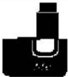 | 9.6V9704897046 |
12.0V97150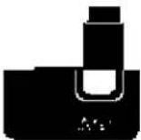 | 12.0'9705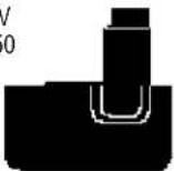 |
14.4V97152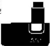 | NOTE: Your tool will accept either standard or Extended Run Time battery packs. However, you must be sure to select the proper voltage. |
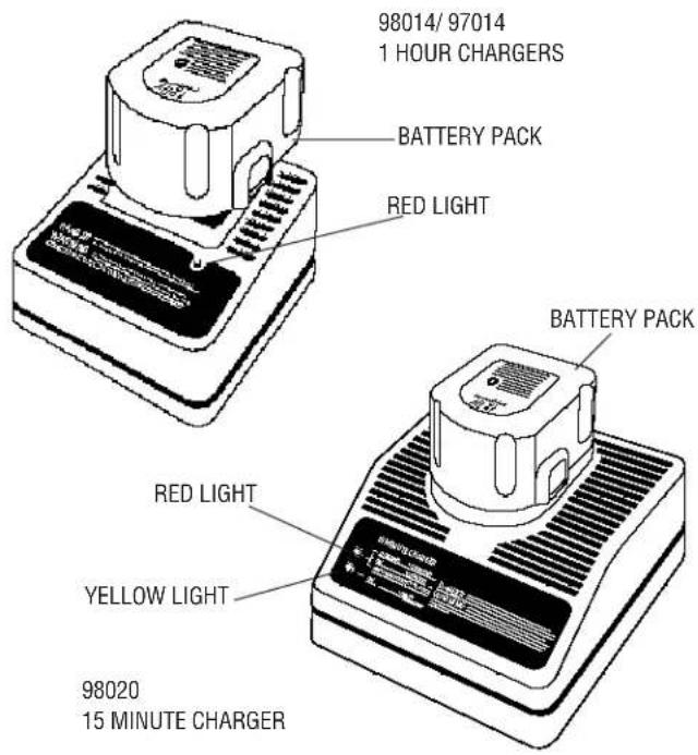
Battery Chargers (98014, 97014 & 98020)
Your battery can be charged in the 98014, 97014 (1 Hour Chargers) or the 98020 (15 Minute Charger). Be sure to read all safety instructions before using your charger. (see page 5 for charging procedure)
text_image
98014/ 97014 1 HOUR CHARGERS BATTERY PACK RED LIGHT BATTERY PACK RED LIGHT YELLOW LIGHT 98020 15 MINUTE CHARGERSAFETY RULES FOR CHARGERS
- Before using charger, read all instructions and cautionary markings on (1) charger, (2) battery pack, and (3) product using battery pack.
- DANGER: 120 volts present at charging terminals. Do not probe with conductive objects. Danger of electric shock or electrocution.
- If battery pack case is cracked or damaged, do not insert into charger. Danger of electric shock or electrocution.
- The charger and battery pack are specifically designed to work together. DO NOT attempt to charge the battery pack with any chargers other than the ones in this manual.
- Do not expose charger to rain or snow.
- These chargers are not intended for any uses other than charging Univolt™ or Cyclone Series™ rechargeable batteries. Any other uses may result in risk of fire, electric shock or electrocution.
- To reduce risk of damage to electric plug and cord, pull by plug rather than cord when disconnecting charger.
- Make sure cord is located so that it will not be stepped on, tripped over, or otherwise subjected to damage or stress.
- An extension cord should not be used unless absolutely necessary. Use of improper extension cord could result in risk of fire, electric shock, or electrocution.
- Two wire cords can be used with 2 or 3 wire extension cords. Only round jacketed extension cords should be used, and we recommend that they be listed by Underwriters Laboratories (U.L.) (C.S.A. in Canada.) The letters WA on the cord jacket indicate that the cord is suitable for outdoor use.
- An extension cord must have adequate wire size (AWG or American Wire Gauge) for safety. The smaller the gauge number of the wire, the greater the capacity of the cable, that is 16 gauge has more capacity than 18 gauge. When using more than one extension to make up the total length, be sure each individual extension contains at least the minimum wire size.
CHART FOR MINIMUM WIRE SIZE (AWG) OF EXTENSION CORDS NAMEPLATE RATING AMPS - 0 - 10.0
Total Extension Cord Length (feet) 25 50 75 100 125 150 175 Wire Gauge 18 18 16 16 14 14 12
- The charger is ventilated through slots in the top and the bottom of the housing. Do not place any object on top of the charger or place the charger on a soft surface that might block the ventilation slots and result in excessive internal heat. Place the charger in a position away from any heat source.
- Do not operate charger with damaged cord or plug — have them replaced immediately.
- Do not operate charger if it has received a sharp blow, been dropped, or otherwise damaged in any way; take it to an authorized B&D service center.
- Do not disassemble charger; take it to an authorized B&D service center when service or repair is required. Incorrect reassembly may result in a risk of electric shock, electrocution or fire.
- To reduce risk of electric shock, unplug charger from outlet before attempting any cleaning. Removing the battery pack will not reduce this risk.
- NEVER attempt to connect 2 chargers together.
- DO NOT store or use the tool and battery pack in locations where the temperature may reach or exceed 105^ F (such as outside sheds or metal buildings in summer).
- The charger is designed to operate on standard household electrical power (120 volts). Do not attempt to use it on any other voltage!
SAVE THESE INSTRUCTIONS FOR FUTURE USE
SAFETY RULES FOR BATTERIES
The batteries in your new battery pack are not fully charged out of the carton! First read the safety instructions below. Then follow charging notes and procedures.
WARNING: When using electric tools, basic safety precautions should always be followed to reduce risk of fire, electric shock, and personal injury, including the following:
- Read all instructions.
- Do not incinerate the battery pack even if it is severely damaged or is completely worn out. The battery pack can explode in a fire.
- A small leakage of liquid from the battery pack cells may occur under extreme usage or temperature conditions. This does not indicate a failure. However, if the outer seal is broken and this leakage gets on your skin:
a. Wash quickly with soap and water.
b. Neutralize with a mild acid such as lemon juice or vinegar.
c. If battery liquid gets into your eyes, flush them with clean water for a minimum of 10 minutes and seek immediate medical attention. (Medical note: The liquid is 25-35% solution of potassium hydroxide.) - Never attempt to open the battery pack for any reason. If the plastic housing of the battery pack breaks or cracks, immediately discontinue use and do not recharge.
-
Do not carry extra battery packs in aprons, pockets, or tool boxes along with other metal objects. Battery pack could be short circuited causing damage to the battery pack and possibly causing severe burn or fire.
-
Charge the battery packs listed on page 2 only in Univolt™ or Cyclone Series™ chargers.
-
NOTE: Review and observe all of the "Important Charging Notes" in the charger instruction section of this manual.
NOTE: After several years of normal use, the batteries in your battery pack will no longer accept a charge. This is a normal occurrence and signifies that the batteries have reached the end of their useful life. Replacement battery packs are available at extra cost from your local B&D service center. Your battery pack contains nickel cadmium batteries. The Environmental Protection Agency considers cadmium to be toxic material that can do severe damage to the environment. Check with your state Environmental Protection agency to find out how to properly recycle or dispose of cadmium, or you can turn in expired battery packs to your local B&D service center for proper recycling or disposal.
SAVE THESE INSTRUCTIONS FOR FUTURE USE
Introduction
The 98014 and 97014 chargers are designed to charge battery packs in about 1 hour. The 98020 charger is designed to charge battery packs in about 15 minutes.
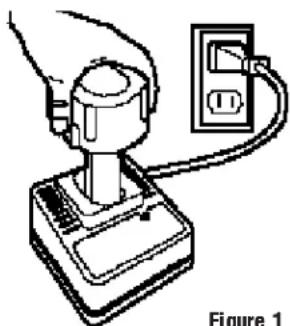
These chargers require no adjustment and are designed to be as easy as possible to operate. Simply place your battery pack into the receptacle of a plugged in charger, as shown in Figure 1, and it will automatically charge the pack.
Charging Procedure
98014/97014 (1 Hour Chargers) only
- Plug the charger into an appropriate AC power outlet.
- Insert the battery pack into the charger, as shown in Figure 1, making sure the pack is fully seated in the charger. The red (charging) light will blink continuously indicating that the charging process has started.
- The battery pack will be fully charged in about 1 hour under most conditions. The completion of charge will be indicated by the red light remaining ON continuously. The pack is fully charged and may be used at this time or left in the charger.
98020 (15 Minute Charger) only
- Plug the charger into an appropriate AC power outlet. The charger will beep twice and the red light will blink and then go off.
- Insert the battery pack into the charger, as shown in Figure 1, making sure the pack is fully seated in the charger. The red light will blink and the charger will beep once indicating the charging process has started.
- The battery pack will be fully charged in less than 15 minutes under most conditions. This will be indicated by the red light remaining ON and 3 audible beeps. The pack is fully charged and may be used at this time or left in the charger.
Leaving the battery pack in the charger
When the red light remains ON, the charger has switched to its “equalize charge” mode which lasts approximately 4 hours, after which the charger will switch to “maintenance charge” mode. The battery pack can be removed at any time during these charge cycles, but will only be fully charged if the red light is continuously ON. The charger and battery pack can be left connected with the red light glowing indefinitely. The charger will keep the
battery pack fresh and fully charged.
NOTE: A battery pack will slowly lose its charge when kept out of the charger. If the battery pack has not been kept on maintenance charge, it may need to be recharged before use. A battery pack may also slowly lose its charge if left in a charger that is not plugged into an appropriate AC source.
natural_image
Simple line drawing of a hand holding a plug and connecting to an electrical outlet (no text or symbols)Figure 1
Trouble Indicators
These chargers are designed to detect certain problems that can arise with battery packs which would be indicated by the red light flashing at a fast rate and continuous beeping. If this occurs, re-insert battery pack. If problem persists, try a different battery pack to determine if the charger is OK. If the new pack charges correctly, then the original pack is defective and should be returned to a Service Center for recycling. If the new battery pack elicits the same trouble indication as the original pack, have the charger tested at an authorized Service Center.
Weak Battery Packs (98020) only
The charger can also detect a weak battery. Such batteries are still usable but should not be expected to perform as much work. In such cases, about 10 seconds after battery insertion, the charger will beep rapidly 8 times to indicate a weak battery condition. The charger will then go on to charge the battery to the highest capacity possible.
IMPORTANT CHARGING NOTES
- Longest life and best performance can be obtained if the battery pack is charged when the air temperature is between 65^ F and 75^ F ( 18^-24^ C). DO NOT charge the battery pack in an air temperature below +40^ F (+4.5°C), or above +105^ F (+40.5°C). This is important and will prevent serious damage to the battery pack.
- The charger and battery pack may become warm to touch while charging. This is a normal condition, and does not indicate a problem.
- (98020 Only) This charger has an internal temperature limit that, when exceeded, will temporarily stop the full charge current. This is indicated by the yellow light being ON. The normal charge cycle will resume when the temperature falls below the preset limit and will be indicated by the yellow light turning OFF. The charge time may be extended beyond the normal 15 minutes. Use the charger in normal room temperatures whenever possible. To prevent overheating, do not cover the charger and do not charge battery packs in direct sunlight or near heat sources.
- If the battery pack does not charge properly — (1) Check current at receptacle by plugging in a lamp or other appliance, (2) Check to see if receptacle is connected to a light switch which turns power off when you turn out the lights. (3) Move charger and battery pack to a location where the surrounding air temperature is approximately 65^ F - 75^ F ( 18^ - 24^ C). (4) If charging problems persist, take or send the tool, battery pack and charger to your local service center.
-
The battery pack should be recharged when it fails to produce sufficient power on jobs which were easily done previously. DO NOT CONTINUE to use under these conditions. Follow the charging procedure. You may also charge a partially used pack whenever you desire with no adverse effect on the battery pack.
-
Under certain conditions, with the charger plugged into the power supply, the exposed charging contacts inside the charger can be shorted by foreign material. Foreign materials of a conductive nature such as, but not limited to, steel wool, aluminum foil, or any buildup of metallic particles should be kept away from charger cavities. Always unplug the charger from the power supply when there is no battery pack in the cavity. Unplug charger before attempting to clean.
- Do not immerse charger in water or any other liquid.
- WARNING: Don't allow any liquid to get inside charger. Electric shock may result.
- To facilitate the cooling of the battery pack after use, avoid placing the charger or battery pack in a warm environment such as in a metal shed, or an uninsulated trailer.
- CAUTION: Never attempt to open the battery pack for any reason. If the plastic housing of the battery pack breaks or cracks, return to a service center for recycling.
Important!
This product is not user servicable. There are no user servicable parts inside the charger. Servicing at an authorized service center is required to avoid damage to static sensitive internal components.
READ ALL OF THE INSTRUCTIONS IN THE BATTERY CHARGER SECTION OF THIS MANUAL BEFORE ATTEMPTING TO CHARGE THE BATTERY PACK FOR YOUR TOOL.
Always use correct battery pack (pack supplied with tool or replacement pack exactly like it.) See chart on inside cover to determine correct battery pack voltage. Never install any other battery pack. It will ruin your tool and may create a hazardous condition.
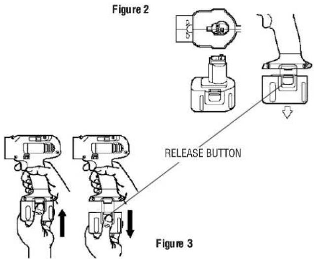
Removing and Installing the Battery Pack
NOTE: YOUR BATTERY PACK WILL NOT BE FULLY CHARGED OUT OF THE CARTON.
To install the battery pack into the tool handle, align the base of the tool with the notch inside the tool's handle and slide the battery pack firmly into the handle until you hear the lock snap into place as shown in Figures 2 and 3.
To remove the battery pack from the tool, press the release buttons, as shown in Figure 3, and firmly pull the battery pack out of the tool handle. Insert it into the charger as described in the charger section of this instruction manual.
text_image
Figure 2 RELEASE BUTTON Figure 3TOOL OPERATION
To turn the tool "ON," squeeze the trigger switch. To turn the tool "OFF," release the trigger switch (Figure 4). Your driver/drill is equipped with a brake. The chuck will stop as soon as the trigger switch is fully released.
Your driver/drill is equipped with a variable speed switch which enables you to select the best speed for a particular application. The farther you squeeze the trigger, the faster the tool will operate.
Use lower speeds for starting holes without a centerpunch, drilling in metals or plastics, driving screws and drilling ceramics, or in any application requiring high torque. Higher speeds are better for drilling in wood, wood compositions and for using abrasive and polishing accessories. For maximum tool life, use variable speed only for starting holes or fasteners.
NOTE: Continuous use in variable speed range is not recommended. It may damage the switch and should be avoided.
Figure 4
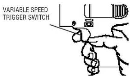
text_image
VARIABLE SPEED TRIGGER SWITCHForward/Reverse Control Button
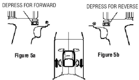
A forward/reverse control button determines the direction of the tool and also serves as a "lock off" button. To select forward rotation, release the trigger switch and depress the forward/reverse control button on the right side of the tool, as shown in Figure 5a.
To select reverse, depress the forward/reverse control button on the left side of the tool as shown in Figure 5b. The center position of the control button locks the tool in the "OFF" position as shown in Figure 5c.
When changing the position of the forward/reverse control button, be sure the trigger is released.
NOTE: The first time the tool is run after changing the direction of rotation, you may hear a click on start up. This is normal and does not indicate a problem.
text_image
DEPRESS FOR FORWARD DEPRESS FOR REVERSE Figure 5a Figure 5bFigure 5c
CENTER POSITION: LOCKED OFF
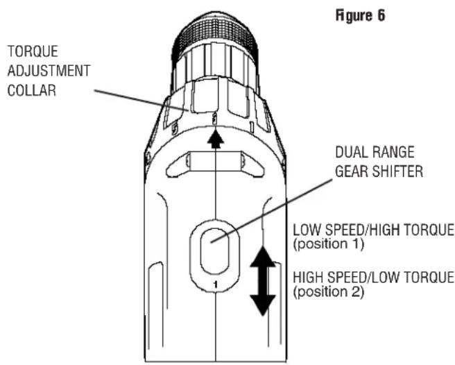
Torque Adjustment Collar
Your driver/drill has an adjustable torque screwdriver mechanism for driving and removing a wide array of fastener shapes and sizes.
Circling the collar are numbers ranging from 0 to 5, and a drill bit symbol. These numbers (and half numbers designated by dots on the collar) are used to set the clutch to deliver a torque range.
The higher the number on the collar, the higher the torque and the larger the fastener which can be driven. To select any of the numbers, rotate until the desired number aligns with the selector, shown in Figure 6.
text_image
Figure 6 TORQUE ADJUSTMENT COLLAR DUAL RANGE GEAR SHIFTER LOW SPEED/HIGH TORQUE (position 1) HIGH SPEED/LOW TORQUE (position 2)Dual Range Gearing
The dual range feature of your driver/drill allows you to shift gears for greater versatility.
To select the low speed, high torque setting, turn the tool off and permit the unit to stop. Slide the gear shifter forward (towards the chuck - position 1), as shown in Figure 6.
To select the high speed, low torque setting, turn the tool off and permit the unit to stop. Slide the gear shifter back (away from chuck - position 2).
NOTE: Do not change gears when the tool is running.
Refer to the chart below to determine the available speeds of your model of driver/drill.
Troubleshooting Tip!
If you are having trouble changing gears, make sure that the dual range gear shifter is either completely pushed forward or completely pushed back.
| Catalog No. Low Range High Range | ||
| 2755 0 - 400 0 - 11002840 0 - 400 0 - 12002852 0 - 450 0 - 14002757 0 - 400 0 - 12002861 0 - 450 0 - 1450 |
Keyless Chuck
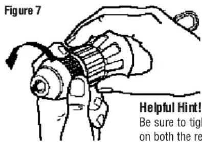
Your tool features a keyless chuck for greater convenience. To insert a drill bit or other accessory, follow the steps listed below.
- Lock the trigger switch in the OFF position as shown in Figure 5c.
- Grasp the rear half of the chuck with one hand and use your other hand to rotate the front half counterclockwise, as shown in Figure 7. Rotate far enough so that the chuck opens sufficiently to accept the desired accessory.
- Insert the bit or other accessory about 3/4" into the chuck and tighten securely by holding the rear half of the chuck and rotating the front portion in the clockwise direction.
To release the accessory, repeat step 2 listed above.
WARNING: Do not attempt to tighten drill bits (or any other accessory) by gripping the front part of the chuck and turning the tool on. Damage to the chuck and personal injury may result. Always lock off trigger switch when changing accessories.
text_image
Figure 7 Helpful Hint! Be sure to tigh on both the reBe sure to tighten chuck with two hands- one on both the rear sleeve and the forward sleeve for maximum tightness.
Chuck Removal
Always wear eye protection.
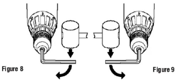
Lock off the tool and turn the adjustment collar to the "drill" position and low speed gear shifter to position 1. Tighten the chuck around the shorter end of a hex key (not supplied) of 1/4 or greater size. Using a wooden mallet or similar object, strike the longer end in the clockwise direction, as shown in Figure 8. This will loosen the screw inside the chuck.
Open chuck jaws fully, insert screwdriver (or Torx tool if required) into front of chuck between jaws to engage screw head. Remove screw by turning clockwise (left-hand-thread). Place hex key in chuck and tighten, as shown in Figure 9. Using a wooden mallet or similar object, strike key sharply in the counter clockwise direction. This will loosen the chuck so that it can be unscrewed by hand.
Chuck Installation
Lock off the tool. Screw the chuck on by hand as far as it will go. Tighten the chuck around the shorter end of a 1/4" or larger hex key (not supplied) strike the longer end in the clockwise direction with a wooden mallet, as shown in Figure 8. Insert and tighten the screw by turning in a counter clockwise direction.
text_image
Figure 8 Figure 9Operation as a Drill
Turn the collar to the drill bit symbol. Install and tighten the desired drill bit in the chuck. Select the desired speed/torque range using the dual range gear shifter to match the speed and torque to the planned operation.
Follow these instructions for best results when drilling.
Drilling
- Use sharp drill bits only. For WOOD, use twist drill bits, spade bits, power auger bits, or hole saws. For METAL, use high speed steel twist drill bits or hole saws. For MASONRY, such as brick, cement, cinder block, etc., use carbide-tipped bits.
- Be sure the material to be drilled is anchored or clamped firmly. If drilling thin material, use a "back-up" block to prevent damage to the material.
- Always apply pressure in a straight line with the bit. Use enough pressure to keep the drill bit biting, but do not push hard enough to stall the motor or deflect the bit.
- Hold tool firmly to control the twisting action of the drill.
- IF DRILL STALLS, it is usually because it is being overloaded. RELEASE TRIGGER IMMEDIATELY, remove drill bit from work, and determine cause of stalling. DO NOT CLICK TRIGGER OFF AND ON IN AN ATTEMPT TO START A STALLED DRILL - THIS CAN DAMAGE THE DRILL.
- To minimize stalling on breaking through the material, reduce pressure on drill and ease the bit through the last fractional part of the hole.
- Keep the motor running when pulling the bit back out of a drilled hole. This will help prevent jamming.
- With variable speed drills there is no need to center punch the point to be drilled. Use a slow speed to start the hole and accelerate by squeezing the trigger harder when the hole is deep enough to drill without the bit skipping out. Operate at full on after starting the bit.
Drilling in Wood
Holes in wood can be made with the same twist drills used for metal. These bits may overheat unless pulled out frequently to clear chips from the flutes. For larger holes, use low speed wood bits. Work that is likely to splinter should be backed up with a block of wood.
Drilling in Metals
Use a cutting lubricant when drilling metals. The exceptions are cast iron and brass which should be drilled dry. The cutting lubricants that work best are sulphurized cutting oil or lard oil; bacon grease will also serve the purpose.
Drilling in Masonry
Use carbide tipped masonry bits at low speeds. Keep even force on the drill but not so much that you crack the brittle materials. A smooth, even flow of dust indicates the proper drilling rate.
Operation as a Screwdriver
Select the desired speed/torque range using the dual range gear shift lever on the top of tool to match the speed and torque to the planned operation.
Insert the desired fastener accessory into the chuck as you would any drill bit. Set the torque adjustment collar (Figure 6). Make a few practice runs in scrap or unseen areas to determine the proper position of the clutch collar.
MAINTENANCE
CLEANING: With the motor running, blow dirt and dust out of all air vents with dry air at least once a week. Wear safety glasses when performing this. Exterior plastic parts may be cleaned with a damp cloth and mild detergent. Although these parts are highly solvent resistant, NEVER use solvents.
Charger Cleaning Instructions:
WARNING: Disconnect the charger from the AC outlet before cleaning. Dirt and grease may be removed from the exterior of the charger using a cloth or soft non-metallic brush. Do not use water or any cleaning solutions.
Accessories
Recommended accessories for use with your tool are available at extra cost from your distributor or local service center. A complete listing of service centers is included with your tool.
CAUTION: The use of any non-recommended accessory may be hazardous.
If you need any assistance in locating any accessory call 1-800-9-BD TOOL (1-800-923-8665) or contact Black & Decker (U.S.) Inc., Consumer Services Department, P.O. Box 618, 626 Hanover Pike, Hampstead, MD 21074.
Maximum Recommended Capacities
Low Range- 1 High Range- 2
| BITS, METAL DRILLING 3/8" 1/4" | |
| WOOD, FLAT BORING 1" 5/8" |
IMPORTANT!
To assure product safety and reliability, particularly for Double Insulated tools, repairs, maintenance and adjustment (excluding maintenance described in this manual) should be performed by B&D service centers or authorized service centers, using identical B&D replacement parts.
Every B&D tool is of the highest quality. If you wish to contact us regarding this product, please call toll free between 8:00am and 8:00pm ET, seven days a week
1-800-9-BD TOOL (1-800-923-8665)
One Year Service/Safety Check
All B&D tools for Industry and Construction are covered under a service/safety check program where B&D will inspect your tool for safety and provide necessary maintenance or repairs, including normal wear and tear parts, for one year, FREE OF CHARGE.
Full Warranty
All B&D tools for Industry and Construction are warranted to be free of any defects in materials or workmanship. Upon thorough examination of tool, B&D will repair or replace, at our option, any product that is determined to be defective.
Conditions
The service/safety check and the warranty do not apply to: repairs made or attempted by anyone other than an authorized B&D service location; misuse, abuse, neglect, improper application of the tool; missing parts; or normal wear and tear (after first year of ownership). Please return the complete unit, transportation prepaid, to any B&D factory owned or B&D authorized service center location (list provided with tool or see Yellow Pages under "Tools Electric").