
TIL1X3AP - Wall mount for screen Chief - Free user manual and instructions
Find the device manual for free TIL1X3AP Chief in PDF.


| Product Type | Wall Mount for LED Panels |
| Brand | Chief |
| Model | TIL1X3AP |
| Manufacturer | Legrand AV |
| Number of Screens Supported | 3 |
| Weight Capacity per Screen | 20 lbs (9.1 kg) |
| Total Weight Capacity | 60 lbs (27.2 kg) |
| Material | Steel |
| Color | Black |
| Mounting Type | Fixed Wall Mount |
| Compatible Display Types | LED Panels Only |
| Wall Compatibility | Wood stud, steel stud, concrete block (with proper anchors) |
| Maximum Drywall Thickness | 5/8 in (1.6 cm) |
| Recommended Wall Backing | 3/4 in plywood |
| Accessories Included | Side connectors, mounting hardware |
| Optional Accessories | TILVAB1 Vertical Connector Kit (sold separately) |
| Safety Factor | Must support 5x combined weight of equipment |
| Usage | Indoor only |
| Cleaning | Wipe with a dry cloth |
Frequently Asked Questions - TIL1X3AP Chief
User questions about TIL1X3AP Chief
0 question about this device. Answer the ones you know or ask your own.
Ask a new question about this device
Download the instructions for your Wall mount for screen in PDF format for free! Find your manual TIL1X3AP - Chief and take your electronic device back in hand. On this page are published all the documents necessary for the use of your device. TIL1X3AP by Chief.
USER MANUAL TIL1X3AP Chief
INSTALLATION INSTRUCTIONS
natural_image
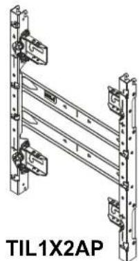
Technical line drawing of a TIL1X2AP mechanical assembly (no text or symbols on the diagram itself)
natural_image
Technical line drawing of a metal frame structure labeled TIL1X3AP (no other text or symbols)
natural_image
Technical line drawing of a TIL1X4AP frame structure (no text or symbols on the diagram itself)
natural_image
Technical line drawing of a TIL1X5AP structural frame with mounting brackets and mounting holes (no text or symbols on the diagram itself)TILVAB1 Accessory

natural_image
Technical line drawing of two metal bracket components with multiple screws (no text or symbols)AP Series LED Wall Mounts / Accessory
DISCLAIMER
Legrand | AV and its affiliated corporations and subsidiaries (collectively “Legrand | AV”), intend to make this manual accurate and complete. However, Legrand | AV makes no claim that the information contained herein covers all details, conditions or variations, nor does it provide for every possible contingency in connection with the installation or use of this product. The information contained in this document is subject to change without notice or obligation of any kind. Legrand | AV makes no representation of warranty, expressed or implied, regarding the information contained herein. Legrand | AV assumes no responsibility for accuracy, completeness or sufficiency of the information contained in this document.
Chief® is a registered trademark of Legrand AV Inc.
DEFINITIONS
MOUNTING SYSTEM: A MOUNTING SYSTEM is the primary Chief product to which an accessory and/or component is attached.
ACCESSORY: AN ACCESSORY is the secondary Chief product which is attached to a primary Chief product, and may have a component attached or setting on it.
COMPONENT: A COMPONENT is an audiovisual item designed to be attached or resting on an accessory or mounting system such as a video camera, CPU, screen, display, projector, etc.

WARNING: A WARNING alerts you to the possibility of serious injury or death if you do not follow the instructions.

CAUTION: A CAUTION alerts you to the possibility of damage or destruction of equipment if you do not follow the corresponding instructions.

IMPORTANT SAFETY INSTRUCTIONS

WARNING: Failure to read, thoroughly understand, and follow all instructions can result in serious personal injury, damage to equipment, or voiding of factory warranty! It is the installer's responsibility to make sure all mounting systems are properly assembled and installed using the instructions provided.

WARNING: Failure to provide adequate structural strength for this mounting system can result in serious personal injury or damage to equipment! It is the installer's responsibility to make sure the structure to which this mounting system is attached can support five times the combined weight of all equipment. Reinforce the structure as required before installing the mounting system. The wall to which the mounting system / accessory is being attached may have a maximum drywall thickness of 5/8" (1.6cm). Do not install drywall anchors into the seam between drywall pieces.

WARNING: The TIL1X2AP / TIL1X3AP / TIL1X4AP / TIL1X5AP LED wall mounts are designed for use with LED panels only. Exceeding the weight capacity (listed) can result in serious personal injury or damage to equipment!
• TIL1X2AP: 40 lbs (18.1 kg) - 20 lbs (9.1 kg) per screen;
• TIL1X3AP: 60 lbs (27.2 kg) - 20 lbs (9.1 kg) per screen;
• TIL1X4AP: 80 lbs (36.3 kg) - 20 lbs (9.1 kg) per screen.
• TIL1X5AP: 100 lbs (45.4 kg) - 20 lbs (9.1 kg) per screen.

WARNING: Use this mounting system only for its intended use as described in these instructions. Do not use attachments not recommended by the manufacturer.

WARNING: Never operate this mounting system if it is damaged. Return the mounting system to a service center for examination and repair.

WARNING: Do not use this mounting system outdoors.
IMPORTANT ! : The TIL1X2AP / TIL1X3AP / TIL1X4AP / TIL1X5AP LED wall mounts are designed to be mounted to:
- a bare 8" concrete or 8"x8"x16" concrete block wall; or
- a 3/4" thickness plywood-backed, 2" x 4" wood studs (16" on center minimum) wall with a maximum drywall thickness of 5/8"; or
- a 3/4" thickness plywood-backed, steel stud wall covered with drywall having a maximum thickness of 5/8".
--SAVE THESE INSTRUCTIONS--
LEGEND
 | Tighten Fastener |  | Pencil Mark |
| Apretar elemento de fijación | Marcar con lápiz | ||
| Befestigungsteil festziehen | Stiftmarkierung | ||
| Apertar fixador | Marcar com lápis | ||
| Serrare il fissaggio | Segno a matita | ||
| Bevestiging vastdraaien | Potloodmerkteken | ||
| Serrez les fixations | Marquage au crayon | ||
 | Loosen Fastener |  | Drill Hole |
| Aflojar elemento de fijación | Perforar | ||
| Befestigungsteil lösen | Bohrloch | ||
| Desapertar fixador | Fazer furo | ||
| Allentare il fissaggio | Praticare un foro | ||
| Bevestiging losdraaien | Gat boren | ||
| Desserrez les fixations | Percez un trou | ||
 | Phillips Screwdriver |  | Open-Ended Wrench |
| Destornillador Phillips | Llave de boca | ||
| Kreuzschlitzschraubendreher | Gabelschlüssel | ||
| Chave de fendas Phillips | Chave de bocas | ||
| Cacciavite a stella | Chiave a punte aperte | ||
| Kruiskopschroevendraaier | Steeksleutel | ||
| Tournevis à pointe cruciforme | Clé à fourche | ||
 | Hex-Head Wrench |  | By Hand |
| Llave de cabeza hexagonal | A mano | ||
| Sechskantschlüssel | Von Hand | ||
| Chave de cabeça sextavada | Com a mão | ||
| Chiave esagonale | A mano | ||
| Zeskantsleutel | Met de hand | ||
| Clé à tête hexagonale | À la main |
TABLE OF CONTENTS
DISCLAIMER 2
DEFINITIONS 2
IMPORTANT SAFETY INSTRUCTIONS 2
LEGEND 3
TABLE OF CONTENTS 4
TOOLS REQUIRED FOR INSTALLATION ....5
PARTS 5
PRE-INSTALLATION 6
Site Assessment 6
INSTALLATION 7
Adding Vertical Connector Kit ....7
If Starting LED Wall Installation With the Top Row 7
If Starting LED Wall Installation With the Bottom Row 7
Adding Side Connectors ....7
Assessing the Installation Site 8
Installing First Mount 8
Adding Additional Mounts 11
Connecting Mounts Side to Side 11
Checking Placement and Alignment 13
Connecting Mounts Above or Below First Row 16
Installing the LED Cabinets 17
Connecting the Cabinets 18
Fastener Installation Methods 19
Wood Stud 19
Concrete or Concrete Block 19
Steel Stud 19
Site Requirements for Wood or Steel Stud Installation 20
DIMENSIONS 21
TOOLS REQUIRED FOR INSTALLATION
![7/32" + 7/32" 3/8" 1/2" #2, #3 Level [2 ft. long] [4+ ft. long] [6+ ft. long] [Small level] 5/32" (included) 1/2" DLETIC Bright colored string T-Handle drive with 3/4" (19mm) Hardware Required - not included (for installation into steel stud walls) 1. Chief brand FCAT1 Togger Kit; OR 2. Hardware for installation to steel stud wall: • 1/4-20 Togger Snaptoggle BB (Qty 4) • 1/4-20 x 2-1/2" hex head bolt (Qty 4) • 1/4" washer (Qty 4) Additional Suggestions 4. Ratcheting wrenches 1. Dead blow hammer 5. Laser level 2. Masking tape 6. Tools required for LED 3. Offset screwdrivers Most likely metric.](/content/2026/06/1196252/images/a15fb082b1ab8d41d481615ac23791fb9002c8a08cdbcf025bf60415928c081b.jpg)
PARTS
![TiL1XXAP Hardware Kit A (6) #10 x 1/2" B (2) 1/4" D (1) 5/32" C (6) 10-24 x 1" E (6) 1/4-20 x 1/2" F (2) [Side connector] G (1) [Adjustment washer-RIGHT] H (1) [Adjustment washer-LEFT] J (4) [UX10x60R anchor] K (4) 5/16 x 2-1/2" L (4) 5/16" M (1) TIL1X2AP OR M (1) TIL1X3AP OR M (1) TIL1X4AP OR M (1) TIL1X5AP TILVAB1 Vertical Connector Kit P (2) [Vertical connector] N (8) 1/4-20 x 1/2"](/content/2026/06/1196252/images/ccdaa7643a647572461312ae05cf2fa6d17198d3bdf56ef32dd518aa8904670e.jpg)
PRE-INSTALLATION
IMPORTANT ! : Reference the LED screen installation manual for specific instructions regarding care, handling, cabling and installation of the LED screens.

CAUTION: Handle the LED screens with care, being careful to not impact or drop the LED screen.

CAUTION: There is a magnetic surface on the front of the LED screen. To prevent damage ensure that no metallic object is pulled onto the LED screen.
NOTE: When planning the installation, remember the requirement to run power and signal to the video wall. Ensure there is also adequate clearance for the plug head. Recessed outlets or angled plugs may be required.
Site Assessment
Before beginning any installation the site should be assessed in several areas to help avoid any issues during the actual installation.
- Wall Structure - It is recommended that a 3/4" furniture-grade plywood-backed wall be used in most LED video walls. The use of a wood stud wall is not appropriate since the studs won't be in the proper location for an LED video wall.
- Wall High/Low Points - Locate any high or low points on the wall that may cause problems, and try to set up install so that these points can be avoided, if possible.
- Flatness/Plumb of Wall - Learn how much depth adjustment will be needed across the LED video wall mounting area.
- Power/Cable - Locate all power outlets and cable access holes that need to be cleared by the installation. Plan appropriately for those holes.
- Installing in a Recess - Verify the level and squareness of the recessed area. Since these areas are rarely perfect you may need to decide what to use as a reference point.
- The recess top or bottom may not be level so the video wall may need to be installed to align with the recess, rather than being level with the wall.
- If the recess is not square the sides may make the recess look crooked. If possible, the recess should be fixed. If repairing the recess isn't an option it may be best to "split the difference" between the recess sides to make the video wall appear level.
- Where to Begin the Video Wall - The installer should make the decision whether the video wall will be started at the top, bottom, left, right or center.
- If a lower bottom reference is given in the specifications, it may make sense to start at the bottom of the video wall to ensure that this specification is met from the start of installation.
- If building inside of a recess, it may be easier to start in the center of the space since the video wall will most likely need to be centered within the recess.
- Vertical/Side Connector Brackets - If creating a video wall with more than a single row, or more than one mount you will be using the side connector brackets which are included with the mounts and/or the vertical connectors which are sold separately.
- Vertical Connector Brackets - If the video wall requires multiple rows, decide on whether the installation will start with the top or bottom row. This determines to which end (top or bottom) the vertical connector brackets are attached.
- Side Connector Brackets - Determine whether it is best to start the installation on the left or right side, or the center. This determines to which side the side connector brackets are installed.

Just a tip - For larger LED walls it is helpful to check placement and alignment of the mounts by putting a few cabinets without the LED's in place in the bottom row of the installed mounts (referencing the LED screen installation manual for specific instructions) during the mount installation, verifying that everything is staying aligned and level, and then continuing the mount installation.

Just a tip - The horizontal slots located along the vertical mount pieces (and vertical slots located along the horizontal mount pieces) are the center-of-screen indicators to illustrate where the center of each LED screen will be located, and can be used to hold a tape measure tab while measuring. (See Figure 1)
![= Center-of-screen indicators Tape Measure [TIL1X3AP shown as example]](/content/2026/06/1196252/images/ed3e91d12b49b479980038c47459a2955c2b3114ace4fb302cdebf3971833382.jpg)
Figure 1
INSTALLATION
Adding Vertical Connector Kit
NOTE: If more LED screens will need to be added to the top or bottom of the screen configuration, add TILVAB1 vertical connector kit to top or bottom of wall mount using the following instructions. If you are NOT adding the TILVAB1 connector kit, proceed to Installing First Mount section.
IMPORTANT !: Install the vertical connector kit BEFORE the mounts are attached to the wall.
If Starting LED Wall Installation With the Top Row
NOTE: If you're starting the installation at the top of the LED video wall, the vertical connector brackets should be attached to the BOTTOM of the mounts to create the top row and each successive lower row.
- Slide the vertical connector (P) up from the bottom of the mount, and attach with two 1/4-20 x 1/2" Phillips pan head screws (N) per vertical connector. (See Figure 2)
- Loosely install one 1/4-20 x 1/2" Phillips pan head screw (N) in the upper screw hole at the bottom of each vertical connector (P). (See Figure 2)

Figure 2
If Starting LED Wall Installation With the Bottom Row
NOTE: If you're starting the installation at the bottom of the LED video wall, the vertical connector brackets should be attached to the TOP of the mounts to create the bottom row and each successive upper row.
- Slide the vertical connector (P) down from the top of the mount, and attach with two 1/4-20 x 1/2" Phillips pan head screws (N) per vertical connector. (See Figure 4)
- Loosely install one 1/4-20 x 1/2" Phillips pan head screw (N) in the lower screw hole at the top of each vertical connector (P). (See Figure 4)

Figure 3
Adding Side Connectors
NOTE: To assist in mount installation, install the side connectors BEFORE the mounts are attached to the wall.
NOTE: When installing the mounts from left to right, all side connectors should be attached to the RIGHT side of the mounts. The last mount will not require any brackets.
NOTE: When installing the mounts from right to left, all side connectors should be attached to the LEFT side of the mounts. The last mount will not require any brackets.
NOTE: When installing the mounts from the center of the video wall all side connectors should be attached on BOTH sides of the center mount.
- For remaining mounts, connectors should be attached on the RIGHT side of the mount for all mounts installed to the LEFT of the center mount.
-
For remaining mounts, connectors should be attached on the LEFT side of the mount for all mounts installed to the RIGHT of the center mount.
-
Loosely install two 1/4-20 x 1/2" button head cap screws (E) into the mount for each side connector. (See Figure 4)
- Hang the connector (F) on the loosely installed screws using the teardrop slots. (See Figure 4)
![Mount (E) x 2 Teardrop slots (F) [Mount shown with connectors attaching to right side]](/content/2026/06/1196252/images/5d71d2bff193c7588761d5fbcd938fc9efa941e053d8e4185a013bd69fd10e91.jpg)
Figure 4
Assessing the Installation Site
IMPORTANT ! : The top of the LED panel is 5" above the top of the UPPER mounting slots, and the bottom of the LED panel is 5.74" below the top of the LOWER mounting slots. (See Figure )
NOTE: If desired, the mount installation may be started in the middle of the video wall, attaching mounts out from the center to the left and right ends. (Review Site Assessment section for further information.) Installation on smaller walls may be easier if started at the left or right side of the video wall using the following instructions.

Just a tip - It is often a good idea to review installation instructions and dimensional drawings (at end of instructions), and then utilize masking tape to lay out the entire LED video wall to lessen the chance of any surprises later in the installation.
- Determine top or bottom panel height location and horizontal placement of mounts. (See Figure 5)
-
Make a mark 5" below the planned top edge (or 5.74"above the planned lower edge of the LED wall. (See Figure 5)
-
Using a level, mark a horizontal line across width of LED wall from the mark made in Step 2.
NOTE: This line will be located at the top of the mounting slots across the width of the LED video wall. The oversize mounting slots will allow some upward adjustment as needed. (See Figure)
![Top of LED cabinet 5" 2 3 Horizontal mark through top of mount slots 2 5.74" Bottom of LED cabinet [TIL1X3AP mount shown as example]](/content/2026/06/1196252/images/60a75bbea572523b4f8f9aa090deadb14c2ec7d5b63d0b503944b664fee9872d.jpg)
Figure 5
Installing First Mount
The TIL1X2AP / TIL1X3AP /TIL1X4AP LED wall mounts are designed to be mounted to:
- a bare 8" concrete wall or 8"x8"x16" concrete block wall; or
- a 3/4" thickness plywood-backed, 2" x 4" wood studs (16" on center minimum) wall with a maximum drywall thickness of 5/8"; or
- a 3/4" thickness plywood-backed, steel stud wall covered with drywall having a maximum thickness of 5/8".
Table 1: Fastener Information
| WALL TYPE | PILOT HOLE | FASTENERS (see PARTS drawing) |
| Drywall attached to plywood-backed walls /Steel studs | 1/2" | - 1/4-20 x 2-1/2" hex head lag (not included)- 1/4" washer (not included)- 1/4-20 Toggler Snaptoggle BB (not included) |
| Drywall attached to plywood-backed walls /Wood studs | 7/32" x 3" | - 5/16 x 2-1/2" flanged hex head lag (K)- 5/16" washer (L)- Adjustment washers (G, H) |
| Concrete or concrete block | 3/8" x 3" - | 5/16 x 2-1/2" flanged hex head lag (K)- 5/16" washer (L)- Adjustment washers (G, H)- Fischer Anchor UX10x60R (J) |
-
Make final decision on where to begin the LED video wall installation (left, right or center; and top or bottom).
-
Make sure the side connectors are attached to the correct side of the mounts, and the vertical connectors are attached to top or bottom depending on installation decision.
-
Place mount against wall matching the top of the mounting slots with the horizontal line previously drawn.
-
Mark mounting holes in two top mounting slots along the horizontal line marked in Step 3 of Assessing the Installation Site section. (See Figure 6)
NOTE: The mounting holes are 15" apart on-center. (See Figure 6)

Figure 6
- Drill two pilot holes (see Table 1 for size) at each location marked in Step 4 (See Figure 6) and follow fastener information (appropriate for wall type) located in Table 1.
IMPORTANT ! : Refer to Fastener Installation Methods (located in Appendix at end of Installation Instructions) for details on installing product into various wall types.
- Partially install two lag screws into wall, but do NOT completely tighten to wall. (See Figure 7)
NOTE: Utilizing the two adjustment washers (G, H) allows the installer to pre-install the top mounting fasteners and hang the mount from them utilizing the mounting slots. This allows the weight of the mount to be held by the mounting bolts during installation, and not the installer.
![[TIL1X2AP shown as example]](/content/2026/06/1196252/images/3c4bc04828531404c4669e01863f9432a14c4f7b7237eaaac4c0421d906e3269.jpg)
Figure 7
-
Hang wall mount, aligning upper mounting slots over fasteners, and adjust side-to-side for proper location. (See Figure 7)
-
Place a level across front of the mount at bottom of teardrop slots. (See Figure 8)
-
Check the level of the mount at the teardrop slots. (See Figure 8)

Figure 8
- Slide the left (H) and right adjustment washers (G) into place behind the partially installed lag screws. (See Figure 9)
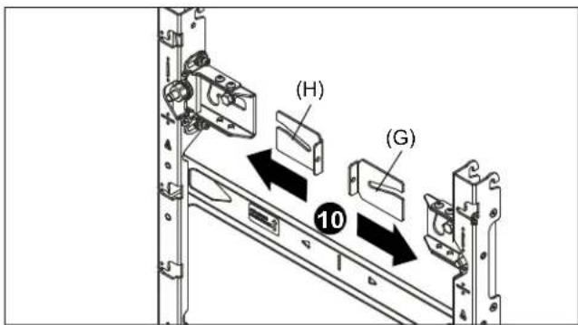
Figure 9
- Check the level of the mount at the bottom of the teardrop slots. (See Figure 10)
- If the mount is not level, slide or use a dead blow hammer to lightly tap the spacer into place. This will lift the mount up as the lag screw rides in the washer's angled slot. (See Figure 10)

Just a tip - Tighten down the lag screw on the side that does NOT need to be raised. This creates a pivot point for when the opposite adjustment washer is tapped into place, and allows that correct side of the mount to move up.
- When the mount is leveled, tighten the lag screws (K). (See Figure 10)

Figure 10
- Drill pilot holes in centerline of lower slots (see Table 1 for size) and follow fastener information (appropriate for wall type) located in Table 1. (See Figure 11)
- Double check the level of the mount at the bottom of the teardrop slots. (See Figure 11)
- Fully tighten the 5/16 x 2-1/2" lag screws (K) through the 5/16" fender washers (L). (See Figure 11)

Figure 11

Just a tip - After the first mount is installed, it may be easier to adjust the plumb at this time. If a lot of adjustment is going to be necessary it's best to adjust it right away to avoid any twist or tension on the mount.
- Using a level on the front of the mount in various places, use a 3/4" or 19mm socket and T-handle driver to adjust the leveling feet on the mount until the mount is plumb or even with something that is being used as a reference point. (See Figure 12)

CAUTION: Over-torquing may cause damage. Do NOT use a drill to make the depth adjustment.
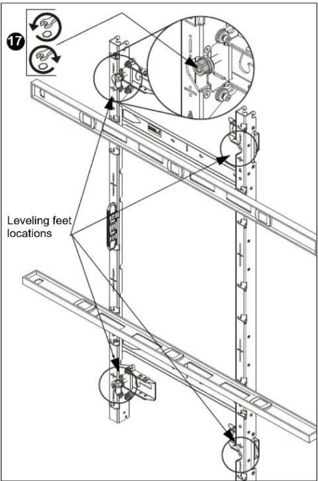
Figure 12
Adding Additional Mounts
Connecting Mounts Side to Side

Just a tip - To assist in mount installation, install the side connectors BEFORE the mounts are attached to the wall. See previous Adding Side Connectors section.
- Loosely install two 1/4-20 x 1/2" button head cap screws (E) with two 1/4" washers (B) into the second mount (being added to the first mount). (See Figure 13)
- Hang the mount by the installed screws (installed in Step 1) onto the side connectors on the first mount. (See Figure 13)
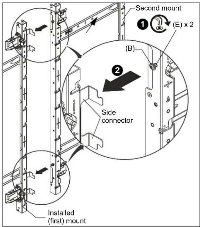
Figure 13
- Once the second mount is hung on the brackets, tighten up the screw on each bracket.
- Check the plumb of the second mount against the previously installed mount and adjust so that both mounts are on the same plane. (See Figure 14)

Figure 14

Just a tip - The plumb on these mounts at this point doesn't have to be perfect. Final adjustments can be done once all the mounts are installed. Checking and adjusting plumb at this point ensures the mounts are closely aligned on the same plane to prevent the mount from twisting or bending when the lag screws are installed.
- Drill pilot holes towards top and in centerline of upper mounting slots on second mount (see Table 1 for size) and follow fastener information (appropriate for wall type) located in Table 1. (See Figure 15)
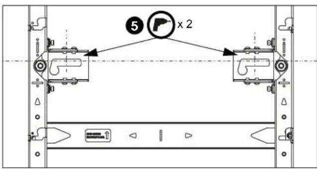
Figure 15

Just a tip - The lag screws need to be at the top of the mounting slot to allow the mount to be raised slightly, if needed, to align it with the previously installed mount.
- Hang second wall mount, aligning upper mounting slots over fasteners, and adjust side-to-side for proper location.
- Slide the left (H) and right adjustment washers (G) into place behind the partially installed lag screws.
- Loosen the side connector screws, upper and lower, prior to adjusting the mount height. (See Figure 16)
- Place a level across front of the mount at bottom of teardrop slots and check that mounts are level and in line with each other. (See Figure 16)
- If mount needs to be raised: use the adjustment washers to raise the second mount.
- Re-tighten connector screws, upper and lower. (See Figure 16)
- Drill lower pilot holes at the center both vertically and horizontally within lower mounting slots and use same fasteners used at top of mount.
- Continue installation of mounts in this manner until the row is complete.

Figure 16
Checking Placement and Alignment
- The holes around slots on the mounts can be used for the included #10 x 1/2" self-tapping screws (A) to help attach a string to help in aligning and plumbing the mounts.
NOTE: There are multiple points on each mount where the screws can be installed for the plumb line. At a minimum, the plumb strings should be strung next to each adjustment point (at every leveling foot). (See Figure 17)
-
Loosely install the self-tapping screws then wrap the string around the screw and tighten. (See Figure 17)
-
Run the string tightly between the same hole at each end of the row of mounts. (See Figure 17)

Figure 17
- Install one or two #10 x 1/2" Phillips self-tapping screws (A) into the edge of the mounting button slots on the far left mount. One or two is typically all that is needed per mount. (See Figure 18)
NOTE: These center-aligning stop screws provide a stop to the mounting button, keeping the cabinet centered on the mount. They are ONLY installed on the furthest left column of mounts, and can be removed later if the mount needs to be slid to the left or right for alignment.
![4 Install self- tapping screws into one or two of the locations indicated. 5 (A) x 1 or 2 [TIL1X3AP shown as example]](/content/2026/06/1196252/images/18a1329626fc968edad4274b9a22c94d3737ad874d26014e9a8a40d4bd14074f.jpg)
Figure 18
- If the cabinets need to be moved slightly to either the left or right, remove the center-aligning tap screws installed in Step 4.
- Insert one 10-24 x 1" self-tapping screw (C) into the left side of the mount. (See Figure 19)
NOTE: There are two places on each cabinet for the left side stop screws to be installed. These screws will act as an adjustable left stop. Turn the screw IN to adjust the stop to the right, and back the screw OUT to move the stop to the left.

Figure 19
-
Attach the mounting buttons to the cabinets using hardware that was included with the LED cabinets and panels.
-
When installing a row of cabinets, slide some of the connector bolts on the cabinets into place to make sure the cabinets are aligned and the bolts slide easily into place. (See Figure 20)
- After the bottom row of cabinets are installed, it is a good idea to install the far left column of cabinets to check that everything is square and straight. (See Figure 20)

Just a tip - When installing in a recess it may also be helpful to install the far right column. This allows you to check for squareness and level inside of the recess.
- When installing a column of cabinets to check alignment, it is a good idea to ensure that the guide pins all slide into place easily. (See Figure 20)
- When done checking alignment with the cabinets, remove the cabinets and proceed with the installation.

Just a tip - When doing the final install, start at the left column and work to the right. Install one column at a time, and then slide it out of the way to the left before installing the next column.


When adding cabinets in a row, ensure that connector bolts easily slide into place between cabinets
Figure 20
Connecting Mounts Above or Below First Row
• Hanging Mounts from an Upper Row
-
Hang the lower mount on the partially installed Phillips head screws (E) in the vertical connectors (P). (See Figure 21)
-
Tighten both lower screws (E) on both vertical connectors (P). (See Figure 21)

Figure 21
• Installing Mounts onto a Lower Row
-
Make sure the 1/4-20 x 1/2" Phillips head screw (E) is already loosely installed in the vertical connector (P) on both sides of the mount. ((See Figure 22)
-
Slide mount down onto the screws so that upper mount hangs on lower mount.
-
Install two 1/4-20 x 1/2" Phillips head screws (E) into upper hole on both vertical connectors, and tighten all screws. (See Figure 22)
-
Place a long level against front of the mounts and adjust the depth of the newly attached mount to align it with the first, installed mount.
-
Adjust the leveling feet on the newly installed mount so that they are touching the wall.
-
Drill pilot holes in centerline of each mounting slot on each leveling foot of the added mount (see Table 1 for size) and follow fastener information (appropriate for wall type) located in Table 1. (See Figure 23)

Figure 22
-
Double check the level of the mount at the bottom of the teardrop slots, and make sure the new mount stays perfectly aligned with the upper or lower mount to which it was attached. (See Figure 23)
-
Fully tighten the 5/16 x 2-1/2" lag screws (K) through the 5/16" fender washers (L). (See Figure 23)

Figure 23
- Continue on until the entire LED wall is assembled.

Just a tip - When building the LED wall, take your time and continually check the mounts to ensure that everything is staying level and aligned. Periodically check alignment by installing some of the actual LED cabinets, without the LED panels.
Installing the LED Cabinets
NOTE: Chief LED mounts are designed for the LED cabinets to be installed beginning in the lower left corner of the wall.
NOTE: Chief LED mounts are designed for the cabinets to be installed starting with columns, but it is also acceptable to install the bottom row of cabinets first.
- BEFORE installing the first cabinet, ensure that the left side adjustable stop screw OR the left front stop screw is installed. (See Figure 24) and also see the stop screws specific information in Connecting Mounts Side to Side section.
- Install the bottom row of cabinets to ensure that everything is aligned and level.
- Move all cabinets to the right side of the mounting slots. (See Figure 25)
- Install the far left column of cabinets. (See Figure 25)
- Slide left column all the way to the left to allow for clearance when installing the next column. (See Figure 25)

Figure 24

Figure 25
- While installing the cabinets, occasionally check to be sure the connector screws fit and easily slide into place. (See Figure 26)

Just a tip - When installing the cabinets do not force them together. If the alignment pins (See Figure 26) are difficult to insert, the plumb may need to be adjusted or there may be interference somewhere in the installation. Adjust as necessary.

Figure 26
- Do NOT permanently connect the cabinets until they all have been installed.
- Install the second column in the same way as the first column, and be sure everything goes together smoothly.
- Push the second column to the left until it just touches the first column. Do NOT slam the cabinets together.
- Continue until all of the cabinets have been installed.
Connecting the Cabinets

Just a tip - After all the cabinets have been installed, connect the cabinets together with the connector screws.
When connecting the cabinets, start at one point (preferably the lower left corner of the LED wall) and work your way outwards.
Do not connect the cabinets together at multiple points on the wall because this may cause the connectors to pull the cabinets in different directions when the connectors are tightened.
Make sure the front plane of the cabinets are aligned since any misalignment will create problems when the LED panels are installed.
- Install two 10-24 x 1" Phillips head self-tapping (C) right stop screws into the right side of each cabinet after the cabinets have been connected together.
- Tighten right stop screws until contact is made with the mounting button on the cabinet. (See Figure 27)
![[View from behind mounts] ABSEN ABSEN ABSEN ABSEN 12 (C) x 2](/content/2026/06/1196252/images/26f25565a230fe22e4361986d871a842109a52475463d852b42c2bc752a2017c.jpg)
Figure 27
Fastener Installation Methods
IMPORTANT ! : See Table 1 for appropriate hardware and pilot hole sizes for various wall types.
IMPORTANT ! : The expanse of the LED wall will most likely mean that attachment of the wall mounts will not all be in studs. The attachment method will most likely vary throughout the installation, and more than one of the various methods outlined here will most likely be used.
Wood Stud
-
Use one 5/16" x 2-1/2" hex flange head lag bolt (K) and one 5/16" washer (L) through product and into pilot hole. (See Figure 28)
-
Repeat for remaining pilot holes.
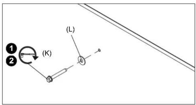
Figure 28
Concrete or Concrete Block
- Install one UX10X60R anchor (J) into each pilot hole using a hammer, making sure that the anchor is flush with the wall. (See Figure 29)
- Use one 5/16" x 2-1/2" hex flange head lag bolt (K) and one 5/16" washer (L) through product into each anchor in wall. (See Figure 29)
- Repeat for remaining pilot holes.

Figure 29
Steel Stud
IMPORTANT ! : See Site Requirements for Steel Stud Installation section before proceeding with Steel Studs installation to ensure installation site meets requirements! The drywall must have a minimum thickness of 1/2"!
- Hold metal channel on anchor flat alongside plastic straps and slide channel through hole. (See Figure 30)

Figure 30
- Holding plastic straps on anchor, pull anchor away from wall until channel rests flush behind wall making sure anchor channel is positioned vertically on drywall, or steel stud (if present). (See Figure 31)
- Slide plastic cap on anchor towards wall until flange of cap is flush with wall. (See Figure 31)
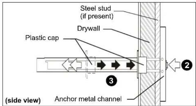
Figure 31
- Snap off plastic straps on anchor at wall by pushing side to side, snapping off straps level with flange of plastic cap. (See Figure 32)
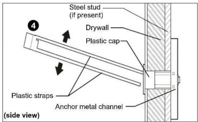
Figure 32
- Line up anchor with attachment point.
- Insert 1/4-20 x 1-3/4" Phillips pan head screw through 1/4" washer, corresponding mounting hole in wall bracket and into anchor, and tighten until flush against wall bracket. DO NOT over tighten! (See Figure 33)

Figure 33
Site Requirements for Wood or Steel Stud Installation

If back side of wall is unfinished, drywall must be installed to a minimum of one stud left and right of the stud(s) being used to install the mount. Drywall must be secured to studs with screws a maximum of 12" (305mm) apart down center of stud.

Steel Stud (2 x 4 / 25ga minimum) Stud type and structural strength must conform to the North American Specification for the Design of Cold-Formed Steel Structural Members. [362 S 125 18, C-Shaped, S-Stud Section]
DIMENSIONS
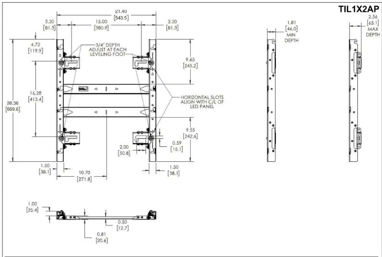
TIL1X2AP
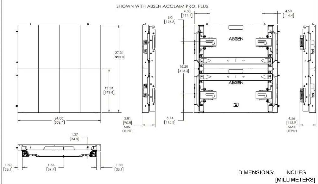
DIMENSIONS: INCHES
[MILLIMETERS]
DIMENSIONS...cont'd

DIMENSIONS...cont'd
SHOWN WITH ABSEN ACCLAIM PRO, PLUS

SHOWN WITH ABSEN ACCLAIM

other
| Dimension | Value | |---|---| | Top Section | 40.51 [1029.0] | | Middle Section | 13.50 [343.0] | | Bottom Section | 24.01 [609.8] |![4.46 [113.3] MIN. DEPTH](/content/2026/06/1196252/images/3842ea1e0dc73a368b32610a368cf4986ffa9f8182617aa310b0dedcce8575ae.jpg)
![4.51 [114.4] 5.0 [126.8] 29.78 [756.4] 5.74 [145.8]](/content/2026/06/1196252/images/4ba4f746c7c0abfe0370ae141fe7505fcd3e543169cb435335b55f1aacf16b2a.jpg)
TIL1X3AP
![5.21 [132.4] MAX. DEPTH](/content/2026/06/1196252/images/f25b1b9bcc5cdd936d79db0a1150408163dca5d9526690694ecaf23367cec2df.jpg)
![1.48 [37.6] 1.31 [33.2] 1.31 [33.2] 1.30 [33.0]](/content/2026/06/1196252/images/4bf1c95c4810978f81187ae1791b042f4c2b3c341f148e593754b46474184d0d.jpg)
DIMENSIONS: INCHES [MILLIMETERS]
DIMENSIONS...cont'd
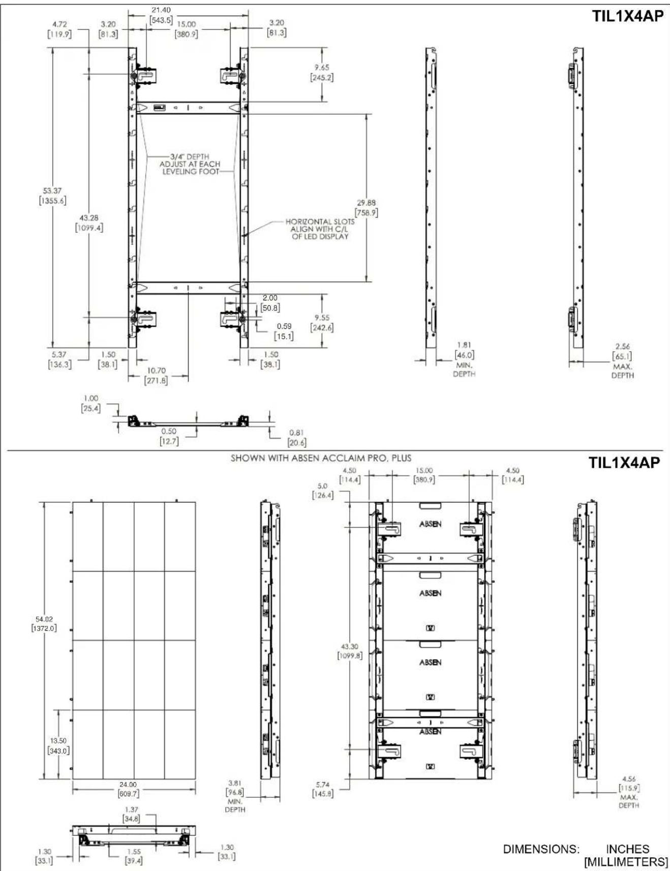
DIMENSIONS:
INCHES
[MILLIMETERS]
DIMENSIONS...cont'd
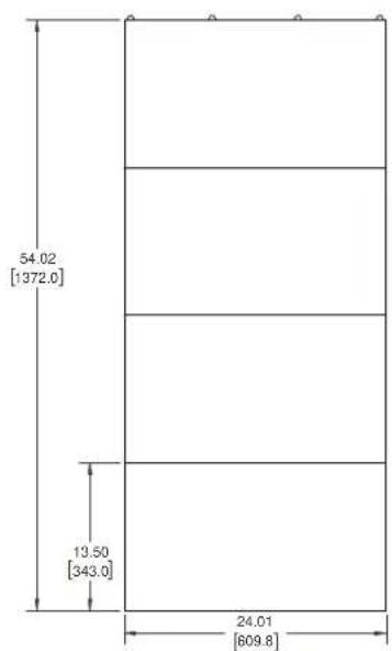
other
| Dimension | Value | |---|---| | Top Height | 54.02 [1372.0] | | Middle Height | 13.50 [343.0] | | Bottom Height | 24.01 [809.8] |SHOWN WITH ABSEN ACCLAIM
![4.46 [113.3] MIN. DEPTH 5.0 [126.4] 43.30 [1099.8] 5.74 [145.8] 4.51 [114,4] 15.00 [380.9] 4.51 [114,4]](/content/2026/06/1196252/images/39b90c4653a7e891a462f9a27e4a08cb0995769b58520c8439377ba159a6e884.jpg)
TIL1X4AP
![5.21 [132.4] MAX. DEPTH](/content/2026/06/1196252/images/64bc6cafff043fedb62782e397acbec24623e53d9016c95270ffff13a2bcac84.jpg)
![1.30 [33.0] 1.31 [33.2] 1.48 [37.6] 1.31 [33.2]](/content/2026/06/1196252/images/77d88fcceb53bde39b189d69f2b89a85e24bf9c3d191df296782d6a84871a4ed.jpg)
![4.72 [119.9] 3.10 [78.8] 21.40 [543.5] 15.19 [385.9] 3.10 [78.8] 9.65 [245.2] 66.87 [1698.6] 3/4" DEPTH ADJUST AT EACH LEVELING FOOT 20.61 [523.5] 56.79 [1442.4] HORIZONTAL SLOTS ALIGN WITH C/L OF LED PANEL 20.61 [523.5] 2.00 [50.8] 9.55 0.59 [242.6] [15.1] 5.37 [136.3] 1.50 [38.1] 10.70 [271.8] 1.50 [38.1]](/content/2026/06/1196252/images/be0c562f0064c4584ad4f7dd3260c0712c489a9533f80935b27fee39ab938135.jpg)

![1.81 [46.0] MIN. DEPTH](/content/2026/06/1196252/images/72791fc447834f7bb4e25d30b7aecdb21ee680d4af2916cfb43ee866210efb7b.jpg)
TIL1X5AP
![2.56 [65.1] MAX. DEPTH](/content/2026/06/1196252/images/22322fdfab09e83c108eccf022405c6cc26ff66728a462f498dedbeb22fbac89.jpg)
DIMENSIONS: INCHES [MILLIMETERS]
DIMENSIONS...cont'd

DIMENSIONS: INCHES [MILLIMETERS]
DIMENSIONS...cont'd
TILVAB1
KIT INCLUDES 2 BRACKETS AND 8 ATTACHMENT SCREWS
![3.50 [88.9]](/content/2026/06/1196252/images/c3c0e941cb3a738fcfe6a4bb83b5b1fc6f82d277a7f13447cb980632f79fd0d3.jpg)
![1.09 [27.8] 1.19 [30.2]](/content/2026/06/1196252/images/35f2f6c2ef319b2fb442533d152f548fe35011b1834539dc5f7783c818c4a3c5.jpg)
ASSEMBLING FROM THE BOTTOM UP
- LEVEL, PLUMB AND ATTACH THE LOWER MOUNT TO THE WALL
- LOOSELY INSTALL THE LOWER BRACKET SCREW
- SLIDE THE UPPER MOUNT DOWN ONTO THE PARTIALLY INSTALLED SCREW
- INSTALL THE UPPER SCREWS ON BOTH SIDES AND TIGHTEN ALL SCREWS
- LEVEL, PLUMB AND ATTACH THE UPPER MOUNT TO THE WALL

natural_image
Technical line drawing of a multi-level mechanical or electrical assembly with no visible text or symbols
LOOSELY INSTALL THE LOWER SCREW BOTH SIDES AND SLIDE THE UPPER MOUNT DOWN ONTO THE SCREWS
DETAIL A
SCALE 1:3

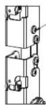
-AFTER THE MOUNT IS SLID INTO PLACE, INSTALL THE UPPER SCREWS, BOTH SIDES, AND TIGHTEN ALL SCREWS
DETAIL B
SCALE 1:3
TILVAB1
natural_image
Technical line drawing of a multi-level electronic device with mounting brackets and connectors (no text or symbols)DIMENSIONS: INCHES [MILLIMETERS]
DIMENSIONS...cont'd
ASSEMBLING FROM THE TOP DOWN
- LEVEL, PLUMB AND ATTACH THE UPPER MOUNT TO THE WALL
- LOOSELY INSTALL THE UPPER BRACKET SCREW
- HANG THE LOWER MOUNT ONTO THE PARTIALLY INSTALLED SCREW
- LOWER THE MOUNT INTO PLACE
- INSTALL THE LOWER SCREWS ON BOTH SIDES AND TIGHTEN ALL SCREWS
- LEVEL, PLUMB AND ATTACH THE LOWER MOUNT TO THE WALL
TILVAB1

natural_image
Technical line drawing of a mechanical assembly with multiple components and mounting holes (no text or symbols)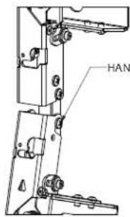
DETAIL C
SCALE 1:3
HANG LOWER MOUNT ON PARTIALLY INSTALLED UPPER SCREWS
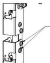
DETAIL D
SCALE 1:3
INSERT ALL SCREWS, BOTH SIDES,
AND TIGHTEN

natural_image
Technical line drawing of a mechanical assembly with multiple vertical rods and mounting holes (no text or symbols)DIMENSIONS: INCHES [MILLIMETERS]
DIMENSIONS...cont'd

other
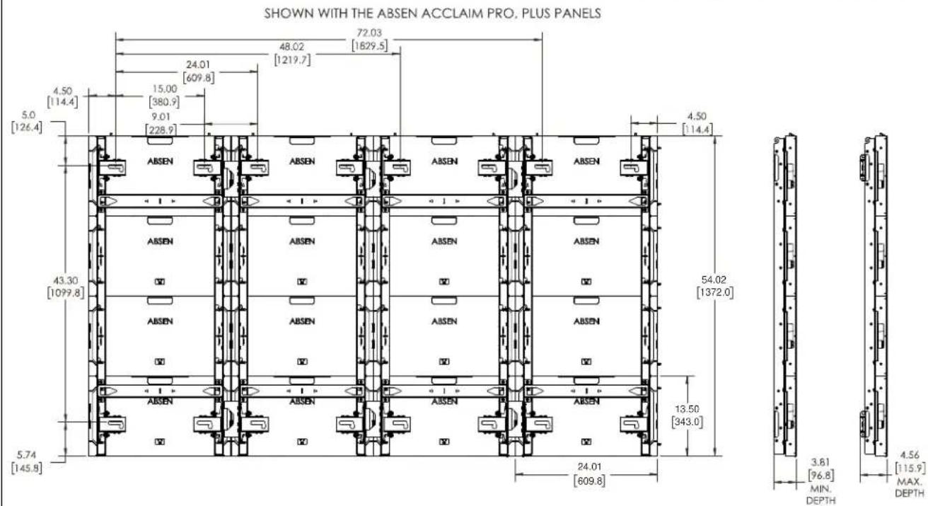
| Dimension | Value | | --------- | ------- | | Total Length | 72.03 | | Height | 1829.5 | | Width | 3.20 | | Thickness | 9.65 | | Thickness | 245.2 | | Thickness | 29.88 | | Thickness | 242.6 | | Thickness | 93.43 | | Thickness | 2373.0 | | Thickness | 53.37 | | Thickness | 136.3 | | Thickness | 53.37 | | Thickness | 1099.4 | | Thickness | 119.9 | | Thickness | 81.3 | | Thickness | 81.3 | | Thickness | 609.8 | | Thickness | 609.8 | | Thickness | 380.9 | | Thickness | 380.9 | | Thickness | 24.01 | | Thickness | 24.01 | | Thickness | 15.00 | | Thickness | 15.00 | | Thickness | 9.01 | | Thickness | 9.01 | | Thickness | 228.9 | | Thickness | 228.9 | | Thickness | 142.5 | | Thickness | 142.5 | | Thickness | 18.40 | | Thickness | 18.40 | | Thickness | 467.3 | | Thickness | 467.3 | | Thickness | 5.61 | | Thickness | 5.61 | | Thickness | 2.61 | | Thickness | 2.61 | | Thickness | 66.3 | | Thickness | 66.3 | | Thickness | 21.40 | | Thickness | 21.40 | TIL1X4AP ConfigurationTIL1X4AP 4X4 CONFIGURATION
other
| Section | Height (m) | |---------|------------| | Top Section | 48.02 | | Middle Section | 72.03 | | Bottom Section | 4.50 | | Total Height | 1629.5 | | Total Width | 114.4 | | Total Length | 126.4 | | Total Height (Top) | 43.30 | | Total Height (Middle) | 54.02 | | Total Height (Bottom) | 13.50 | | Total Length (Bottom) | 145.8 | | Total Width (Bottom) | 115.9 | | Total Length (Top) | 3.81 | | Total Height (Top) | 4.56 | | Total Width (Top) | 96.8 | | Total Length (Bottom) | 609.8 | | Total Height (Bottom) | 609.8 |DIMENSIONS: INCHES [MILLIMETERS]
DIMENSIONS...cont'd
SHOWN WITH ABSEN ACCLAIM PANELS
TIL1X4AP 4X4 CONFIGURATION
![72.03 [1829.5] 48.02 [1219.7] 24.01 [609.8] 15.00 [380.9] 9.01 [228.9] 4.51 [114.4] 5.0 [126.4] 43.30 [1099.8] 5.74 [145.8] 96.04 [2439.4] 24.01 [609.8] 54.02 [1372.0] 13.50 [343.0] 4.46 [113.3] MIN. DEPTH 5.21 [132.4] MAX DEPTH](/content/2026/06/1196252/images/f3baf95569375c7ed1375c54ef1d569806fee9a03d00a5b680501dc453973ee2.jpg)
TIL1X4AP 4X4 CONFIGURATION
WHEN INSTALLING SIDE BRACKETS, IT IS USUALLY EASIER TO INSTALL THE BRACKETS PRIOR TO HANGING THE MOUNT SECTIONS ON THE WALL. THESE BRACKETS CAN BE ATTACHED ON EITHER TO THE LEFT OR RIGHT SIDE.
WHEN INSTALLING THE NEXT MOUNT SECTION, LOOSELY
INSTALL THE 1/4-20 BUTTON HEAD CAP SCREW WITH A WASHER AND HANG THE NEXT SECTION ON THE BRACKET. ADJUST AS NECESSARY BEFORE ATTACHING TO THE WALL.

THE SCREWS CAN BE LOOSELY INSTALLED AND THE BRACKET HUNG UTILIZING THE TEARDROP SLOTS
DIMENSIONS: INCHES [MILLIMETERS]
DIMENSIONS...cont'd

other
| Dimension | Value | | --------- | ------- | | Total Length | 4.72 | | Total Height | 119.9 | | Total Width | 3.10 | | Total Height (Top) | 72.03 | | Total Height (Bottom) | 24.01 | | Total Width (Top) | 609.8 | | Total Width (Bottom) | 223.9 | | Total Height (Top) | 96.04 | | Total Height (Bottom) | 136.3 | | Total Height (Top) | 2439.4 | | Total Width (Top) | 1829.5 | | Total Width (Bottom) | 609.8 | | Total Height (Top) | 245.2 | | Total Height (Bottom) | 223.9 | | Total Width (Top) | 523.5 | | Total Width (Bottom) | 66.87 | | Total Height (Top) | 1698.6 | | Total Height (Bottom) | 242.6 | | Total Height (Top) | 46.0 | | Total Height (Bottom) | 46.0 | | Total Width (Top) | 46.0 | | Total Width (Bottom) | 46.0 | | Total Height (Top) | 65.1 | | Total Height (Bottom) | 65.1 | | Total Height (Top) | 45.1 | | Total Height (Bottom) | 45.1 | | Total Height (Top) | 2.56 | | Total Height (Bottom) | 2.56 | | Total Height (Top) | 2.56 | | Total Height (Bottom) | 2.56 | | Total Height (Top) | 2.56 | | Total Height (Bottom) | 2.56 | | Total Height (Top) | 2.56 | | Total Height (Bottom) | 2.56 | | Total Height (Top) | 2.56 | | Total Height (Bottom) | 2.56 | | Total Height (Top) | 2.56 | | Total Height (Bottom) | 2.56 | | | Total Height (Top) | 2.56 | | Total Height (Bottom) | 2.56 | | Total Height (Top) | 2.56 | | Total Height (Bottom) | 2.56 | | Total Height (Top) | 2.56 | | Total Height (Bottom) | 2.56 | | Total Height (Top) | 2.56 | | TIL1X5AP Configuration | [Data not extractable as needed; values are estimated based on chart labels and data units not explicitly provided in the code.) |TIL1X5AP 5X5 CONFIGURATION

other
| Dimension | Value | | --------- | ----- | | Total Length | 120.04 | | Height [mm] | 3049.1 | | Top Section Width | 96.04 | | Top Section Height | 2439.4 | | Top Section Width | 48.02 | | Top Section Height | 1829.5 | | Top Section Width | 15.19 | | Top Section Height | 609.8 | | Top Section Width | 223.9 | | Bottom Section Width | 67.52 | | Bottom Section Height | 13.50 | | Bottom Section Width | 343.0 | | Bottom Section Height | 56.79 | | Bottom Section Width | 1442.4 | | Bottom Section Height | 145.8 | | Top Section Width | 4.41 | | Top Section Height | 111.9 | | Top Section Width | 111.9 | | Top Section Height | 115.9 | | Top Section Width | 115.9 | | Top Section Height | 115.9 | | Top Section Width | 115.9 | | Top Section Height | 115.9 | | Top Section Width | 115.9 | | Top Section Height | 115.9 | | Top Section Width | 115.9 | | Top Section Height | 115.9 | | Top Section Width | 115.9 | | | Top Section Height | 115.9 | | Top Section Width | 115.9 | | Top Section Height | 115.9 | | Top Section Width | 115.9 | | Top Section Height | 115.9 | | Top Section Width | 115.9 | | Top Section Height | 115.9 | | Top Section Width | 115.9 | | Top Section Width | 115.9 | | Top Section Height | 4.56 | | Top Section Height | 4.56 | | Top Section Width | 3.81 | | Top Section Height | 96.8 | | Top Section Width | MIN. DEPTH | | Top Section Height | MAX. DEPTH | | Top Section Width | MAX. DEPTH | | Top Section Height | MAX. DEPTH | | Top Section Width | MAX. DEPTH | | Top Section Height | MAX. DEPTH | | Top Section Width | MAX. DEPTH | | Top Section Height | MAX. DEPTH | | Top Section Width | MAX. DEPTH | | Top Section Height | MAX. DEPTH | | Top Section Width | MAX. DEPTH | | Top Section Height | MAX. DEPTH | | Top Section Width | MAX. DEPTH | | Top Section Height | MAX DEPTH | | Top Section Width | MAX. DEPTH | | Top Section Height | MAX DEPTH | | Top Section Width | MAX. DEPTH | | Top Section Height | MAX DEPTH | | Top Section Width | MAX. DEPTH | | Top Section Height | MAX DEPTH | | Top Section Width | MAX. DEPTH | | Top Section Height | MAX DEPTH | | Top Section Width | MAX. DEPTH | | Top Section Height | MAX DEPTH | | Top Section Width | MAX. PTHDIMENSIONS: INCHES [MILLIMETERS]
DIMENSIONS...cont'd
TIL1X5AP 5X5 CONFIGURATION
![4.41 [112.0] 15.19 [385.9] 24.01 [609.8] 48.02 [1219.7] 72.03 [1829.5] 96.04 [2439.4] 4.41 [112.0] 2.61 [66.3] 67.52 [1715.0] 56.79 [1442.4] 13.50 [343.0] 24.01 [609.8] 120.05 [3049.2] 4.46 [113.3] MIN. DEPTH](/content/2026/06/1196252/images/86fc942c341533f255187701d0af51cb248d00ebe7a4a18cfc8091af21a386e6.jpg)
TIL1X5AP 5X5 CONFIGURATION
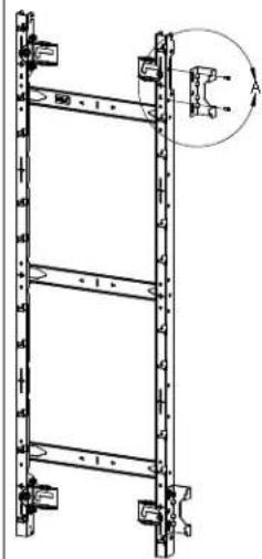
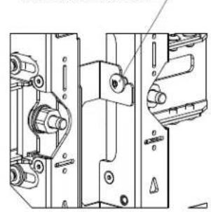
WHEN INSTALLING SIDE BRACKETS, IT IS USUALLY EASIER TO INSTALL THE BRACKETS PRIOR TO HANGING THE MOUNT SECTIONS ON THE WALL. THESE BRACKETS CAN BE ATTACHED ON EITHER THE LEFT OR RIGHT SIDE.
WHEN INSTALLING THE NEXT MOUNT SECTION, LOOSELY INSTALL THE 1/4-20 BUTTON HEAD CAP SCREW WITH A WASHER AND HANG THE NEXT SECTION ON THE BRACKET. ADJUST AS NECESSARY BEFORE ATTACHING TO THE WALL.
natural_image
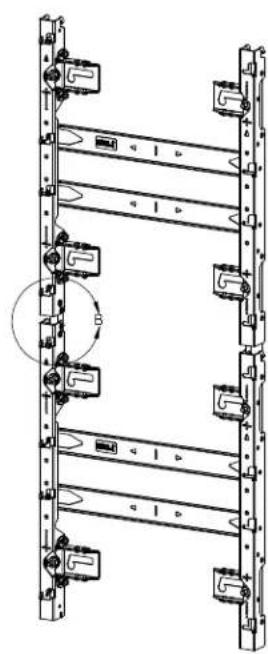
Technical line drawing of a multi-level metal frame structure with mounting brackets and a circular inset showing a mechanical component (no text or symbols)
THE SCREWS CAN BE LOOSELY INSTALLED AND THE BRACKET HUNG UTILIZING THE TEARDROP SLOTS

natural_image
Technical line drawing of a multi-tiered metal frame structure with mounting brackets (no text or symbols)LOOSELY INSTALL THE 1/4-20 BUTTON HEAD CAP SCREW AND WASHER. THEN SET THE NEXT SECTION INTO PLACE
natural_image
Technical line drawing of mechanical components (no text or symbols visible)DETAIL B SCALE 1:2
DIMENSIONS: INCHES [MILLIMETERS]

CHIEF®
A brand of legrand®
8800-003186 Rev00
©2019 Legrand | AV
www.legrandav.com
12/19
USA/International A 6436 City West Parkway, Eden Prairie, MN 55344
P 800.582.6480 / 952.225.6000
F 877.894.6918 / 952.894.6918
Europe A Franklinstraat 14, 6003 DK Weert, Netherlands
P +31 (0) 495 580 852
F +31 (0) 495 580 845
Asia Pacific A Office No. 918 on 9/F, Shatin Galleria
18-24 Shan Mei Street
Fotan, Shatin, Hong Kong
P 852 2145 4099
F 852 2145 4477



- INSTALLATION INSTRUCTIONS
- AP Series LED Wall Mounts / Accessory
- DISCLAIMER
- DEFINITIONS
- IMPORTANT SAFETY INSTRUCTIONS
- --SAVE THESE INSTRUCTIONS--
- TABLE OF CONTENTS
- PRE-INSTALLATION
- Site Assessment
- INSTALLATION
- Adding Vertical Connector Kit
- If Starting LED Wall Installation With the Top Row
- If Starting LED Wall Installation With the Bottom Row
- Adding Side Connectors
- Assessing the Installation Site
- Installing First Mount
- Adding Additional Mounts
- Connecting Mounts Side to Side
- Checking Placement and Alignment
- Connecting Mounts Above or Below First Row
- • Hanging Mounts from an Upper Row
- • Installing Mounts onto a Lower Row
- Installing the LED Cabinets
- Connecting the Cabinets
- Fastener Installation Methods
- Wood Stud
- Concrete or Concrete Block
- Steel Stud
- Site Requirements for Wood or Steel Stud Installation
- DIMENSIONS...cont'd
- TILVAB1
- ASSEMBLING FROM THE BOTTOM UP
- ASSEMBLING FROM THE TOP DOWN
- TIL1X5AP 5X5 CONFIGURATION
Brand : Chief
Model : TIL1X3AP
Category : Wall mount for screen