
DVM27U4 - Wall mount for screen Chief - Free user manual and instructions
Find the device manual for free DVM27U4 Chief in PDF.


| Product Type | Wall mount for screen |
| Brand | Chief |
| Model | DVM27U4 |
| Maximum Screen Size | 65 inches |
| VESA Compatibility | Up to 600x400mm |
| Weight Capacity | 175 lbs (79.4 kg) |
| Mount Type | Fixed, low-profile |
| Tilt Adjustment | 0 to 10 degrees |
| Level Adjustment | ±2 degrees |
| Material | Steel, powder coated |
| Color | Black |
| Dimensions (W x H x D) | 27.3 x 17.2 x 2.8 inches (693 x 437 x 71 mm) |
| Weight | 12 lbs (5.4 kg) |
| Wall Stud Spacing | 16 to 24 inches (406 to 610 mm) |
| Included Hardware | Mounting bolts, spacers, screws, anchors, and tools |
| Warranty | 10 years |
| Cleaning Instructions | Wipe with a soft, dry cloth; avoid solvents |
| Safety Note | Must be mounted to wood studs or solid concrete |
| Compliance | TAA compliant, UL listed |
Frequently Asked Questions - DVM27U4 Chief
User questions about DVM27U4 Chief
0 question about this device. Answer the ones you know or ask your own.
Ask a new question about this device
Download the instructions for your Wall mount for screen in PDF format for free! Find your manual DVM27U4 - Chief and take your electronic device back in hand. On this page are published all the documents necessary for the use of your device. DVM27U4 by Chief.
USER MANUAL DVM27U4 Chief
INSTALLATION INSTRUCTIONS

Universal LED Wall Mounts
DISCLAIMER
Legrand | AV and its affiliated corporations and subsidiaries (collectively "Legrand | AV"), intend to make this manual accurate and complete. However, Legrand | AV makes no claim that the information contained herein covers all details, conditions or variations, nor does it provide for every possible contingency in connection with the installation or use of this product. The information contained in this document is subject to change without notice or obligation of any kind. Legrand | AV makes no representation of warranty, expressed or implied, regarding the information contained herein. Legrand | AV assumes no responsibility for accuracy, completeness or sufficiency of the information contained in this document.
Chief® is a registered trademark of Legrand AV Inc.
DEFINITIONS
MOUNTING SYSTEM: A MOUNTING SYSTEM is the primary Chief product to which an accessory and/or component is attached.
ACCESSORY: AN ACCESSORY is the secondary Chief product which is attached to a primary Chief product, and may have a component attached or setting on it.
COMPONENT: A COMPONENT is an audiovisual item designed to be attached or resting on an accessory or mounting system such as a video camera, CPU, screen, display, projector, etc.

WARNING: A WARNING alerts you to the possibility of serious injury or death if you do not follow the instructions.

CAUTION: A CAUTION alerts you to the possibility of damage or destruction of equipment if you do not follow the corresponding instructions.

IMPORTANT SAFETY INSTRUCTIONS

WARNING: Failure to read, thoroughly understand, and follow all instructions can result in serious personal injury, damage to equipment, or voiding of factory warranty! It is the installer's responsibility to make sure all mounting systems are properly assembled and installed using the instructions provided.

WARNING: Failure to provide adequate structural strength for this mounting system can result in serious personal injury or damage to equipment! It is the installer's responsibility to make sure the structure to which this mounting system is attached can support five times the combined weight of all equipment. Reinforce the structure as required before installing the mounting system. The wall to which the mounting system is being attached may have a maximum drywall thickness of 5/8" (1.6cm). Do not install drywall anchors into the seam between drywall pieces.

WARNING: The DVM27U Series LED wall mounts are designed for use with LED panels only. Exceeding the weight capacity (listed) can result in serious personal injury or damage to equipment! Do NOT attach LED panels to DVM27U LED video wall mounts that exceed 250 lbs (113.4 kg) per column, regardless of the size or design of the configuration. See figure below for example.


WARNING: Use this mounting system only for its intended use as described in these instructions. Do not use attachments not recommended by the manufacturer.

WARNING: Never operate this mounting system if it is damaged. Return the mounting system to a service center for examination and repair.

WARNING: Do not use this mounting system outdoors.
IMPORTANT ! : The DVM27U Series wall mounts are designed to be mounted to:
- an 8"x8"x16" concrete block wall; or
- a 3/4" thickness plywood-backed, 2" x 4" wood studs (16" on center minimum) wall with a maximum drywall thickness of 5/8"; or
- a 3/4" thickness plywood-backed, steel stud wall covered with drywall having a maximum thickness of 5/8".
--SAVE THESE INSTRUCTIONS--
LEGEND
 | Tighten Fastener |  | Pencil Mark |
| Apretar elemento de fijación | Marcar con lápiz | ||
| Befestigungsteil festziehen | Stiftmarkierung | ||
| Apertar fixador | Marcar com lápis | ||
| Serrare il fissaggio | Segno a matita | ||
| Bevestiging vastdraaien | Potloodmerkteken | ||
| Serrez les fixations | Marquage au crayon | ||
 | Loosen Fastener |  | Drill Hole |
| Aflojar elemento de fijación | Perforar | ||
| Befestigungsteil lösen | Bohrloch | ||
| Desapertar fixador | Fazer furo | ||
| Allentare il fissaggio | Praticare un foro | ||
| Bevestiging losdraaien | Gat boren | ||
| Desserrez les fixations | Percez un trou | ||
 | Phillips Screwdriver |  | Adjust |
| Destornillador Phillips | Ajustar | ||
| Kreuzschlitzschraubendreher | Einstellen | ||
| Chave de fendas Phillips | Ajustar | ||
| Cacciavite a stella | Regolare | ||
| Kruiskopschroevendraaier | Afstellen | ||
| Tournevis à pointe cruciforme | Ajuster | ||
 | Open-Ended Wrench |  | Remove |
| Llave de boca | Quitar | ||
| Gabelschlüssel | Entfernen | ||
| Chave de bocas | Remover | ||
| Chiave a punte aperte | Rimuovere | ||
| Steeksleutel | Verwijderen | ||
| Clé à fourche | Retirez | ||
 | By Hand |  | Optional |
| A mano | Opcional | ||
| Von Hand | Optional | ||
| Com a mão | Opcional | ||
| A mano | Opzionale | ||
| Met de hand | Optie | ||
| À la main | En option | ||
 | Hex-Head Wrench |  | Security Wrench |
| Llave de cabeza hexagonal | Llave de seguridad | ||
| Sechskantschlüssel | Sicherheitsschlüssel | ||
| Chave de cabeça sextavada | Chave de segurança | ||
| Chiave esagonale | Chiave di sicurezza | ||
| Zeskantsleutel | Veiligheidssleutel | ||
| Clé à tête hexagonale | Clé de sécurité |
TOOLS REQUIRED FOR INSTALLATION
![[Small level] 7/32" 3/8" [Laser level] String 3/32" (included) 5/32" (included) 1/8" (extender kit ONLY) Level [4+ ft. long] #2 3/4" deep well socket 1/2", 5/16" socket Ratchet or T-handle for use with deep well socket Level [2 ft. long]](/content/2026/06/1250122/images/2f9004ce46fb9dc6037ad45a6971ed741fedc9c7df888f051b1ab0c72f87703f.jpg)
PARTS
![(C) TILED Universal Hardware Bag [Starter - 2, Extender - 1] (quantity per bag) CA (2) 5/16 x 2 1/2" CB (4) #10-24 x 1" set screw CC (2) #8 x 2" CD (3) #6-32 x 3/8" CE (2) 5/16" CF (2) Ux10x60R CG (1) 1 1/4" Quick-release pin CH (1) 3/32" CJ 5/32" or F (1) [Left upright] (2-high extender) G (1) [Right upright] (2-high extender) D (8/12/16)* [M8 mounting button] E (8/12/16)* [M6 mounting button] *(-2-high, 3-high, 4-high)](/content/2026/06/1250122/images/a6191b57f3e270d7d37137d05c5b68884336322cb33f4107d52565791360cf5a.jpg)
DIMENSIONS
DVM27U (2-HIGH)
![2.898 [73.6] MOUNTING PATTERN WIDTH MINUS 5.75 [146.1] 2.898 [73.6] 1.51[48.4] MIN 2.54 [64.5] MAX H BLOCK BUTTON CAPTURE - 2X (POSITION Varies BASED ON MOUNTING PATTERN HEIGHT ) 20.57 [522.5] 26.33 [668.8] MOUNTING PATTERN HEIGHT (VARIABLE) 2.04[51.8] MIN 2.67[67.8] MAX (WITH BUTTON)](/content/2026/06/1250122/images/f5dfa42dc5c7569569e01dd7d078269abbeed7ee841966afeebdbda082ebf409.jpg)
![DEPTH ADJUST.SCREW (3/4" OE 19m m DEEP WELL SOCKET) PLUMB LINE CONNECTION LOCATION N - OX. TOTAL (#6-32 SCREWS INC.UO.SDI) 625 [18.9] 68 [17.1] BASE CARKAGE HOLE FOR LOC KING PIN INCLUDED | HEIGHT / LEVELING ADJUSTMENT SC REW (+2'/0" AS SHIPPED) DETAIL A SCALE 1:1 DETAIL B SCALE 1:1](/content/2026/06/1250122/images/55d6e71d1c40748fc9d0f9bf730a6f6de566927718b5efe580ed881090eb0d8a.jpg)
DVM27U (3-HIGH)
![2.898 [73.6] MOUNTING PA TIERN WIDTH MINUS 5.75 [146.1] 2.898 [73.6] H-SLOCK BUTTON CAPTURE - 6X [POSITION Varies BASED ON MOUNTING PATTERN HEIGHT] 33.86 [840.0] MOUNTING PATTERN HEIGHT [VARIABLE] 39.62 [1006.3] 2.04(51.6) MIN 2.87 (87.8) MAX [WITH BUTTON]](/content/2026/06/1250122/images/8d01d5884a0ac75a8abb5b6cfd63665f96ececec25ed542c85bb3bdd4826c1af.jpg)
![13/4" OR 19mm DEEP WELL SOCKET) PLUMB LINE CONNECTION LO CATION-10X TOTAL (4" 6.32 SCREW'S INCLUDED) 625 [15.9] 68 [17.1] BASE CARRIAGE HOLE FOR LOCKING G PIN (INCLUDED) HEIGHT / LEV EUNG AD JUSTIMENT SC REW (+7.0" AS SHIPPED) DETAIL A SCALE 1:1 DETAIL B SCALE 1:1](/content/2026/06/1250122/images/0324e4637a78d5ccf5637bd6d5621abf69f738d2f75a686f252ccefab44a2d87.jpg)
DIMENSIONS
DVM27U (4-HIGH)
![2.898 [73.6] MOUNTING PA TERN W ID TH MINUS 5.75 [146.1] 2.898 [73.6] 1.91 [48.4] MIN 2.54 [64.5] MAX H B.O CK BUTTON CA PTURE 6X (POSITION Varies BASED ON MOUNTING PATTERN HEIGHT) 47.14 [1197.5] 52.90 [1343.8] MOUNTING PATTERN N HEIGHT [VA RABLE] MOUNTING PATTERN N WIDTH (VARIABLE) 2.04 [51.8] MIN 2.67 [67.8] MAX X (W TH BUTTON N)](/content/2026/06/1250122/images/1af03fa966f619947c50d45a7b90b50f9668d12b46459f63b7384b0ea523f743.jpg)
![DEPTH ADJUST SC REW [3/4" OR 19mm] DEEP WELL SOC KET) FLUW B LINE CO NNECTO N LO CATIO N-10X [TO AL [8 6-32 SCREW S IN CLUDED] .625 [15.9] .68 [17.1] BASE CARRIAGE HOLE FOR LOCKING PIN (INCLUDED) HEIGHT / LEVELING ADJUSTMENT SC REW (+2V-0' AS SHIPPED) DETAIL A SC ALE 1:1 DETAIL B SCALE 1:1](/content/2026/06/1250122/images/80f77f033733ee69cd9d1302eada0d0f159123413c5c05153b8f52d2ff578aea.jpg)
DVM27UE (2-HIGH)
![2.898 [73.6] MOUNTING PATTERN WIDTH MINUS 5.75 [146.1] 2.898 [73.6] H.BLOCK BUTTON N.CA PTU RE-8X [POSITION VARIES BASED ON MOUNTING PATTERN HEG IT] 27.53 [699.4] MOUNTING PATTERN HIG IT [VARIABLE] 26.57 [674.8] 1.54 (49.3) MIN 2.57 (65.3) MAX INSTALL TO P.C AP FROM STARTER SKU TO EXTENDER SKU (2 PLACES) DETAIL A SCALE 1:1 DETAIL B SCALE 2:3 DEPTH A.DJUSTS CREW (3,4" OR 19mm- DEEP W ELLSOCKET) 570 (14.5) EXTRUSION CONNECTOR HEIGHT CO CONNECTOR BLOCK PLUMB LINE CO CONNECTION LOCATION N-8X TOTAL L- (#4-32 SC REWS IN CUCED) A *DVM EXTENDER SKUS MUST ALWAYS BE USED WITH A STARTER SKU* MOUNTING PATTERN WIDTH [VARIABLE] 1.57 (30.5) MIN 2.62 (64.5) MAX (WITH BUTTON)](/content/2026/06/1250122/images/77f76f3650edc2bd1e5d0ae5f155c42c3ffe4f2873b8ce1b65f07141a9f4cc6e.jpg)
DIMENSIONS
DVM27UE (3-HIGH)


MEASUREMENT WORKSHEET - DVM27U (2-HIGH)
![(MPW /2) -2.875 [73.0] MPW - 5.75[146.1] (DW [(DW -MPW)/2] +2.875 [73.0] 10.28 [261.2] 2.898[2-7/8") [3.6] 10.28 [261.2] 20.57 [522.5] DH - 10.28 [261.1] FO RMULA TO CENTER DISPLAYS ON MO UNT OFF MPW 2X DH Q GH DH___IN DW___IN MPH___IN MPW___IN AFF___IN DH___mm DW___mm MPH___mm MPW___mm AFF___mm BOTTOM EDGE OF DISPLAY](/content/2026/06/1250122/images/30e8a57d875bb44eeffa84f30d71ecc72ed5cf60977cdeb74de2d5519d26cb3f.jpg)
DVLED PANEL:
DH = DVLED DISPLAY HEIGHT
DW = DVLED DISPLAY WIDTH
MPH = MOUNTING PATTERN HEIGHT
MPW - MOUNTIN G PATTERN W IDTH
AFF = ABOVE FINISHED FLOOR
MEASUREMENT WORKSHEET - DVM27U (3-HIGH)
![(DW -M PW)/2 [(DW -MPW)/2] +2.875 [73.0] 16.93 [430.0] 33.86 [860.0] 16.93 [430.0] 1.5(DH) -16.93 [430.0] FORMULA TO CENTER DISPLAYS ON MOUNT AFF MPW D W (MPW/2) -2.875 [73.0] M PW - 5.75[146.1] Q 2.898(2-7/8") [73.6] C 3X DH DH___ IN DW___ IN MPH___ IN MPW___ IN AFF___ IN DH___ mm DW___ mm MPH___ mm MPW___ mm AFF___ mm BOTTOM EDGE OF DISPLAY](/content/2026/06/1250122/images/f0bc7779b25aea0ba0637c09ca65b7b53f133d1d1b4c8b6dd66d2ef8276b3e28.jpg)
DVLED PANEL:
DH = DVLED DISPLAY HEIGHT
DW = DVLED DISPLAY WIDTH
MPH = MOUNTING PATTERN HEIGHT
MPW - MOUNTING PATTERN WIDTH
AFF = ABOVE FINISHED FLOOR
MEASUREMENT WORKSHEET - DVM27U (4-HIGH)
![(MW/2) -2.8/5 [73.0] MPW - 5.75 [5.3/4" [146.1] (DW-M PW)/2 [(DW-MPW]/2] +2.875[73.0] 23.57 [598.7] 2.898 [2.7/8" [73.6] 47.14 [1197.5] 23.57 [598.7] GH OF MOUNT TO DISPLAY EDGE [2X DISPLAY HEIGHT] 2(DH) - 23.57 [598.7] FORMULA TO C ENTER DISPLAYS O N MOUNT OFF MPW BOTTOM EDGE OF DISPLAY DH = DVLED DISPLAY HEIG HT DW = DVLED DISPLAY WIDTH MPH = MOUNTING PATTERN HEIGHT MPW - M MOUNTING PATTERN WIDTH AFF = ABOVE FINISHED FLOO R DVLED PANEL:](/content/2026/06/1250122/images/4dee68403c8841529ed542c97df1c9189c2e8900b1f4d5176ab111bd3716ec60.jpg)
INSTALLATION
Preinstallation
IMPORTANT ! : Reference the LED screen installation manual for specific instructions regarding care, handling, cabling and installation of the LED screens.

CAUTION: Handle the LED screens with care, being careful to not impact or drop the LED screen.

CAUTION: There is a magnetic surface on the front of the LED screen. To prevent damage ensure that no metallic object is pulled onto the LED screen.
NOTE: When planning the installation, remember the requirement to run power and signal to the video wall.
Site Assessment
Before beginning any installation the site should be assessed in several areas to help avoid any issues during the actual installation.
- Wall Structure - It is recommended that a 3/4" furniture-grade plywood-backed wall be used in most LED video walls. The use of a wood stud wall is not appropriate since the studs won't be in the proper location for an LED video wall.
- Wall High/Low Points - Locate any high or low points on the wall that may cause problems, and try to set up install so that these points can be avoided, if possible.
- Flatness/Plumb of Wall - Learn how much depth adjustment will be needed across the LED video wall mounting area.
- Power/Cable - Locate all power outlets and cable access holes that need to be cleared by the installation. Plan appropriately for those holes.
-
Installing in a Recess - Verify the level and squareness of the recessed area. Since these areas are rarely perfect you may need to decide what to use as a reference point.
-
The recess top or bottom may not be level so the video wall may need to be installed to align with the recess, rather than being level with the wall.
- If the recess is not square the sides may make the recess look crooked. If possible, the recess should be fixed. If repairing the recess isn't an option it may be best to "split the difference" between the recess sides to make the video wa appear level.
- Where to Begin the Video Wall - The installer should make the decision whether the video wall will be started at the top, bottom, left, right or center.
- If a lower bottom reference is given in the specifications, it may make sense to start at the bottom of the video wall to ensure that this specification is met from the start of installation.
- If building inside of a recess, it may be easier to start in the center of the space since the video wall will most likely need to be centered within the recess.
- Extender mounts - If creating a video wall with more than a single row, you will be using the extender mounts (DVM27U2E/DVM27U3E/DVM27U4E) in addition to the starter mounts (DVM27U2/DVM27U3/DVM27U4).
- Measurement Worksheets - In order to determine mounting hole locations, refer to measurement worksheets on pages 8-10. It may be helpful to print the appropriate sheet and fill in the measurements of the display in the blanks to have as reference for making the proper calculations. (See Figure 1)
(DVM27U - 2 HIGH SHOWN AS EXAMPLE)
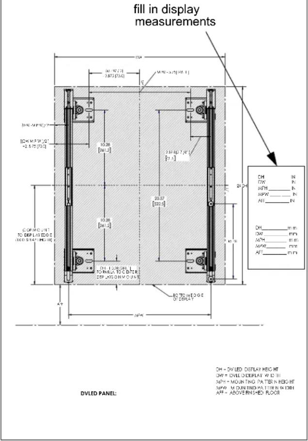
Figure 1

Just a tip - For larger LED walls it is helpful to check placement and alignment of the mounts by putting a few cabinets without the LED's in place in the bottom row of the installed mounts (referencing the LED screen installation manual for specific instructions) during the mount installation, verifying that everything is staying aligned and level, and then continuing the mount installation.
Installation of First Row of Uprights
NOTE: The mount should be installed from bottom to top, installing the entire bottom row first before building up as needed.
NOTE: Refer to dimensions drawings on pages 5-10 for further details on installation locations. Corresponding measurement worksheet may be printed and filled out for quick reference as measurements are made.
- Determine mounting locations for first set of uprights using formulas found on measurement worksheets (pages 8-10).
a. Horizontally
- Odd number of columns: From centerline to middle column = (MPW/2) - 2.875" (73mm).
-
Even number of columns: From seam or edge of display = [(DW-MPW/2)] + 2.875" (73mm).
b. Vertically
• 2-High -
Display edge to bottom mounting point = [1(DH) - 10.28" (261.1mm)].
- Display edge to top mounting point = [1(DH) - 10.28" (261.1mm)] + 20.57 (522.5mm).
• 3-High
- Display edge to bottom mounting point = [1.5(DH) - 16.93" (430mm)].
- Display edge to top mounting point = [1.5)DH) - 16.93" (430mm)] + 33.86 (860mm).
• 4-High
- Display edge to bottom mounting point = [2(DH) - 23.57" (598.7mm)].
-
Display edge to top mounting point = [2(DH) - 23.57" (598.7mm)] + 47.14" (1197.5mm).
-
Draw level horizontal lines at vertical locations determined in Step 2b using a 4-foot level or a laser level. (See Figure 2)
IMPORTANT ! : Make sure to include the above finished floor measurement (AFF) in the calculation to determine mounting locations.
The DVM27U wall mounts are designed to be mounted to the following wall types:
Table 1: Fastener Information
| WALL TYPE PILOT HOLE | FASTENERS (see PARTS drawing) | |
| Drywall attached to plywood-backed walls Steel/Wood studs | 7/32" x 3" | - 5/16 x 2-1/2" flanged hex head lag (CA)- 5/16" flat washer (CE) |
| Concrete or concrete block | 3/8" x 3" | - 5/16 x 2-1/2" flanged hex head lag (CA)- 5/16" flat washer (CE)- Fischer Anchor UX10x60R (CF) |
IMPORTANT ! : The following Steps show installation to drywall attached to plywood-backed wall. For installation into concrete, Fischer Anchor UX10x60R (CF) must be used with 3/8" mounting holes. See Fastener Installation Methods Section for details.
- Mark mounting hole location along upper line based on horizontal locations determined in Step 2a. (See Figure 2)
- Drill a 7/32" at the location of the first upper mounting hole. (See Figure 2)

Figure 2
- Use 5/16 x 2 1/2" hex head lag screw (CA) and 5/16" washer (CE) to loosely install left upright (A) to wall. Center the lag bolt horizontally along mounting slot. PARTIALLY tighten bolt. (See Figure 3)

Figure 3
- Slide the H-blocks together within the extrusion and attach a magnetic 2-foot level to side of upright. (See Figure 4)

Figure 4
- Mark mounting hole location along lower line based on horizontal locations determined in Step 2a. (See Figure 4)
- Level and drill a 7/32" hole at the location of the first lower mounting hole. (See Figure 4)
- Use 5/16 x 2 1/2" hex head lag screw (CA) and 5/16" washer (CE) to install left upright (A) to wall at lower mounting hole. Center the lag bolt horizontally along mounting slot. (See Figure 4)
- Hold mount upright and tighten upper lag bolt (CA) that was partially installed in Step 6. (See Figure 4)

Just a tip - Install a drywall screw (CC) through one of the smaller holes in foot to prevent the upright from "walking" in slot when tightening lag. (See Figure 4)
- Determine and mark the adjacent mounting location along the upper level line using the following formula (See Figure 5):
- MPW [mounting pattern width] - 5.75" (146.1mm)
![MPW - 5.75[146.1] 12 7/32"](/content/2026/06/1250122/images/4337f909cacb39192f3effb4e04a2be255a7ad39c6eb8c5106dc7a71c10191a7.jpg)
Figure 5
- Drill 7/32" mounting hole at marked location. (See Figure 5)
- Use 5/16 x 2 1/2" hex head lag screw (CA) and 5/16" washer (CE) to loosely install right upright (B) to wall. Center the lag bolt horizontally along mounting slot. PARTIALLY tighten bolt. (See Figure 6)

Figure 6
- Slide the H-blocks together within the extrusion and attach a magnetic 2-foot level to side of upright. (See Figure 7)

Figure 7
- Mark mounting hole location along lower line based on horizontal locations determined in Step 2a. (See Figure 7)
- Drill a 7/32" hole at the location of the first lower mounting hole. (See Figure 7)
- Use 5/16 x 2 1/2" hex head lag screw (CA) and 5/16" washer (CE) to install right upright (B) to wall at lower mounting hole. Center the lag bolt horizontally along mounting slot. (See Figure 7)
- Hold mount upright and tighten upper lag bolt (CA) that was partially installed in Step 14. (See Figure 7)

Just a tip - Install a drywall screw (CC) through adjacent hole in foot to prevent the upright from "walking" in slot when tightening lag.
- Use a tape measure to ensure the uprights (A and B) are mounted the proper distance apart from each other based on mounting pattern width (MPW). (See Figure 8)

Figure 8
- (Optional) Install four mounting buttons (D or E) onto back of a display (if available) and install onto H-blocks to ensure the uprights are properly distanced. (See Figure 9) and (See Figure 11)

Figure 9
- Measure one display width (DW) from mounting holes in uprights already installed to mark holes for next set of uprights (A and B). (See Figure 8) and (See Figure 10)

Figure 10
- Drill 7/32" mounting holes at marked locations. (See Figure 10)
- Repeat Steps 6-22 to install left and right uprights (A and B).
- Continue installing uprights until first row is complete.
- Verify the uprights are vertically level with two or four foot level and spaced horizontally (one display width) from matching upright with a tape measure.
- Install mounting buttons (D or E) into one display to be installed. (See Figure 9)
- Install display to mount by inserting lower mounting buttons into the base carriages. (See Figure 11)
- Slide the H-blocks down the extrusion to enclose the upper mounting buttons. (See Figure 11)
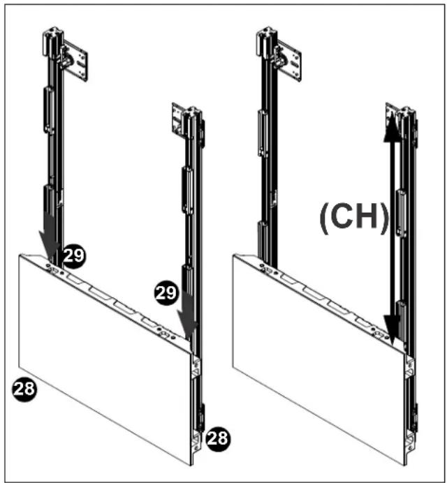
Figure 11
- Use a tape measure to determine coverage height (CH), which is the distance from the top of display to the top of mounting column. (See Figure 11)
-
Compare the coverage height (CH) with remaining display height to determine whether column height needs to be adjusted.
-
2 high: If CH is less than DH, adjust by the difference.
- 3 high: If CH is less than 2 × DH , adjust by the difference.
- 4 high: If CH is less than 3 × DH , adjust be the difference.
- If CH is greater than the formulas listed above, no adjustment is needed.
Sample Calculation
- Mount size 3 high
• Coverage height (CH) = 26.85" (682.0mm)
• Display height (DH) = 13.29" (337.5mm)
- 2 × DH = 26.57'' (675.0) which is less than CH
- Minimum height adjustment for coverage = 26.85" (682.0mm) - 26.57" (675.0mm) = 0.280" (7.0mm).
DVM27U Series Installation Instructions
- If height adjustment is required for the displays to cover the mount, remove display and make the minimum height adjustment determined in Step 31 by adjusting the height adjustment screws using a 5/16" socket driver. (See Figure 12)
![BASE C. ARRIAGE HEIGHT / LEVELING ADJUSTMENT T SCREW [+2'-0' A S SHIPPED] *IF BELOW EQUATIONS ARE FALSE, USE HEIGHT ADJUST SCREW TO ADJUST BOTTOM PANEL UNTIL THEY ARE TRUE* 4 HIGH: CH = 3(DH) 3- HIG H: CH = 2(DH) 2.HIG H: CH = DH **IF ABOVE EQUATIONS ARE INITIALLY TRUE, ADJUSTM ENT SCREW FOR LEVELING ONLY**](/content/2026/06/1250122/images/095e64ef3f2ba97a731ab8b685125a3921145b3afb2184399cd279fec58310d0.jpg)
- Adjust each base carriage on the first column the required amount for coverage. Rest a level across the height-adjustment carriage on each upright to level the carriages on the first row at (or above) the required coverage height. (See Figure 13)
- Adjust the carriages on the adjacent columns to make sure they are level.

Just a tip - Make adjustments to base carriages before hanging mount uprights to wall.
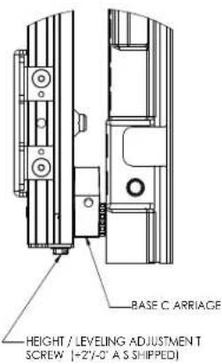
"IF BELOW EQUATIONS ARE 'FALSE', USE HEIGHT ADJUST SCREW TO ADJUST BOTTOM PANEL UNTIL THEY ARE TRUE"
4 HIGH: CH = 3(DH) 3 HIG H: CH = 2(DH) 2.HIG H: CH = DH
**IF ABOVE EQUATIONS ARE INITIALLY 'TRUE', ADJUSTMENT SCREW FOR LEVELING ONLY**
Figure 12

Figure 13
Plumb Leveling
- After the bottom row has been installed and leveled, adjust the outermost uprights away from the wall 1/4" (approximately four full turns) prior to plumbing middle uprights. Uprights should be adjusted to a point that the mount rail extends past the planar face of all the middle uprights. Depth adjustment is controlled by depth adjustment screws on each upright. (See Figure 14)

Just a tip - Slide H-blocks as necessary to attach a magnetic 2-foot level on the mount face to plumb uprights.

Figure 14
- After the outer uprights are plumb, use a #6-32 self-tapping screw (CC) to connect a string line from one outer upright to the other. (See Figure 15)
- Adjust inner uprights until they all touch the string. (See Figure 15)
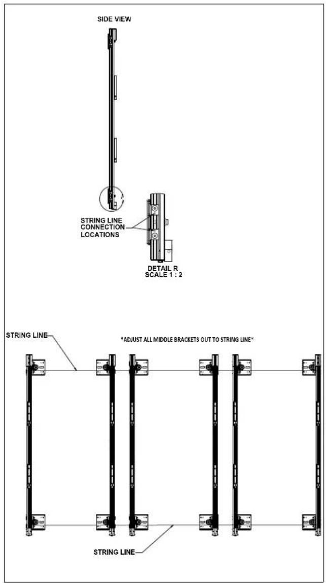
Figure 15
Displays Installation (First Row)
- Install mounting buttons (D or E) into displays to be installed. (See Figure 16)

Figure 16
- Install display to mount by inserting lower mounting buttons into the base carriages. (See Figure 16) and (See Figure 17)
- Slide the H-blocks down the extrusion to enclose the upper mounting buttons. (See Figure 17)

Figure 17
- Make any necessary adjustments using the height/leveling adjustment screws on the bottom of the mounts. (See Figure 12)
- Use a 4-foot level or laser level to ensure bottom row of displays are horizontally level. (See Figure 18)

natural_image
Diagram of a multi-level industrial or mechanical assembly with vertical supports and a central numbered component (no text or symbols)Figure 18
- Continue installing displays following Steps 1-5 until the first row is full.
IMPORTANT ! : If NOT using extender kit (DVM27U2E/DVM27U3E/DVM27U4E), proceed to Building Remaining Wall Section.
Installing Extender Kit (DVM27UE)
- Remove the top button capture bracket by removing two screws on top of starter uprights (A and B). Set bracket and screws aside for re-use. (See Figure 22)

Figure 19
- Remove socket head cap screw and loosen side screws at bottom of extender uprights (F and G) using 1/8" hex key. (See Figure 23)
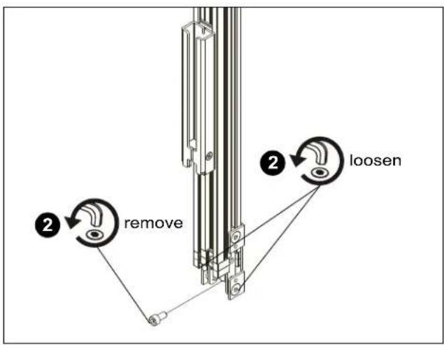
Figure 20
- Insert extender uprights (F and G) into T-slots on starter uprights (A and B). (See Figure 23)
- Tighten side screws and re-install removed socket head cap screw though starter mount extrusion. (See Figure 23)

Figure 21
- Level the extender uprights to ensure they are vertically level with the starter uprights. (See Figure 22)
- Mark mounting hole at each location. (See Figure 22)
- Drill a 7/32" hole at the location of each mounting hole. (See Figure 22)

Figure 22
- Use 5/16 x 2 1/2" hex head cap screws (CA) and 5/16" washers (CE) to secure extender uprights to wall. (See Figure 23)

Figure 23
-
Repeat Steps 2-8 if installing more than one extender upright.
-
After the top extender upright (F or G) is installed, install top button capture bracket and screws (removed in Step 1 of Installing Extender Kit (DVM27UE) Section. (See Figure 24)
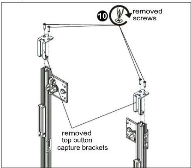
Figure 24
- Continue to install extender uprights across the upper row by repeating Steps 1-9 until row is complete.
- Plumb adjust the upper row of uprights following steps in Plumb Leveling Section.
Building Remaining Video Wall
- Make sure all installed uprights are level.
- Make sure the first row of displays is still level.
- Install displays in a "T" or "L" formation following steps in Displays Installation Section making sure the column is level after installation. (See Figure 25)
- Plumb adjust first column before proceeding to other columns. See Plumb Leveling Section for details.
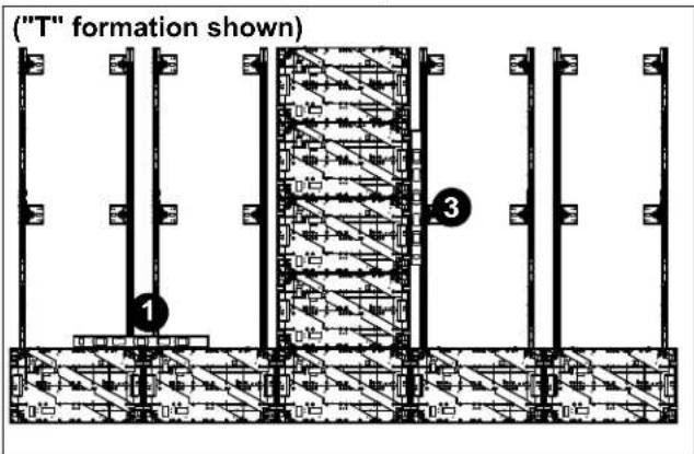
Figure 25
NOTE: Display depth can be adjusted using the mounting buttons either using a small flathead screwdriver from the side or a hex key (CH or CJ) from the front. (See Figure 26)

Figure 26
- Install #10-24 x 1" set screws (CB) into the highest H-block in each column using 3/32" hex key (CH). (See Figure 27)

Figure 27
- Add quick-release pin (CG) to the bottom of each column. (See Figure 28)
NOTE: Pins (CG) may be installed to either side of the column.

Figure 28
- Continue to build columns out until wall is complete following steps in Displays Installation Section.
- Add quick-release pin (CG) to the bottom of each column. (See Figure 28)
- Use display hardware included with display panels (typically threaded shoulder bolts or cam-locks) to connect displays to each other. (See Figure 29)

Figure 29
NOTE: Manage power cables behind displays as the wall is built.
NOTE: Signal cables typically can be connected from the front prior to installing LED modules.
- Install LED modules to displays (if necessary) to complete wall installation. (See Figure 30)

Figure 30
Fastener Installation Methods
IMPORTANT! : See Table 1 for appropriate hardware and pilot hole sizes for various wall types.
IMPORTANT ! : The expanse of the LED wall will most likely mean that attachment of the wall mounts will not all be in studs. The attachment method will most likely vary throughout the installation, and more than one of the various methods outlined here will most likely be used.
Wood Stud/Steel Stud (w/plywood backing)
IMPORTANT ! : The DVM72U LED wall mounts are designed to be mounted to a 3/4" thickness plywood-backed, 2" x 4" wood studs (16" on center minimum) wall with a maximum drywall thickness of 5/8" or a 3/4" thickness plywood-backed, steel stud wall covered with drywall having a maximum thickness of 5/8".
- Use one 5/16" x 2-1/2" hex flange head lag bolt (CA) and 5/16" washer (CE) through product and into pilot hole. (See Figure 31)
- Repeat for remaining pilot holes.

Figure 31
Concrete or Concrete Block
IMPORTANT ! : The DVM27U LED wall mounts are designed to be mounted to a bare 8" concrete or 8"x8"x16" concrete block wall.
- Install one UX10X60R anchor (CF) into each pilot hole using a hammer, making sure that the anchor is flush with the wall. (See Figure 32)
-
Use one 5/16" x 2-1/2" hex flange head lag bolt (CA) and 5/16" washer (CE) through product into each anchor in wall. (See Figure 32)
-
Repeat for remaining pilot holes.

Figure 32
Site Requirements for Wood or Steel Stud Installation

\*Steel stud ONLY
If back side of wall is unfinished, drywall must be installed to a minimum of one stud left and right of the stud(s) being used to install the mount. Drywall must be secured to studs with screws a maximum of 12" (305mm) apart down center of stud.

Steel Stud (2 x 4 / 25ga minimum)
Stud type and structural strength must conform to the North American Specification for the Design of Cold-Formed Steel Structural Members. [362 S 125 18, C-Shaped, S-Stud Section]
Figure 33
CHIEF®
A brand of legrand
8800-003416 Rev00
©2024 Legrand | AV
www.legrandav.com
06/2024
USA/International A 6436 City West Parkway, Eden Prairie, MN 55344
P 800.582.6480 / 952.225.6000
F 877.894.6918 / 952.894.6918
Europe A Franklinstraat 14, 6003 DK Weert, Netherlands
P +31 (0) 495 580 852
F +31 (0) 495 580 845
Asia Pacific A Office No. 918 on 9/F, Shatin Galleria
18-24 Shan Mei Street
Fotan, Shatin, Hong Kong
P 852 2145 4099
F 852 2145 4477



- INSTALLATION INSTRUCTIONS
- DISCLAIMER
- DEFINITIONS
- IMPORTANT SAFETY INSTRUCTIONS
- DIMENSIONS
- INSTALLATION
- Preinstallation
- Site Assessment
- Installation of First Row of Uprights
- Sample Calculation
- DVM27U Series Installation Instructions
- Plumb Leveling
- Displays Installation (First Row)
- Installing Extender Kit (DVM27UE)
- Building Remaining Video Wall
- Fastener Installation Methods
- Wood Stud/Steel Stud (w/plywood backing)
- Concrete or Concrete Block
- Site Requirements for Wood or Steel Stud Installation
- \*Steel stud ONLY
- CHIEF®
Brand : Chief
Model : DVM27U4
Category : Wall mount for screen