
208338 - AV Transmitter Intellinet - Free user manual and instructions
Find the device manual for free 208338 Intellinet in PDF.

| Product Type | H.264 HDMI Over IP Video Wall Extender (Transmitter) |
| Model Number | 208338 |
| Brand | Intellinet |
| Video Input | HDMI (with lock) |
| Video Output | Via LAN (H.264 encoding) |
| Network Interface | RJ-45 Ethernet (10/100 Mbps) |
| Transmission Range | Up to 100 m (330 ft) via Cat5e/6 |
| Video Resolution | Full HD (1920 x 1080) |
| Audio Support | HDMI audio embedded, can be toggled on/off |
| HDCP Compliance | HDCP 1.4 (compliant) |
| Power Supply | 5V DC / 2A (adapter included) |
| LED Indicators | Status (amber) and Power (green) |
| Channel ID Selection | Rotary switch (10 positions for pairing, 16 for video wall) |
| Video Wall Support | Yes, up to 3x3 configurations (e.g., 1x2, 2x2, 3x3) |
| Maximum Transmitters | 10 |
| Maximum Receivers | 246 (model 208345) |
| Management Software | Intellinet Video Wall Management UI (downloadable) |
| Mounting | VESA mountable (hardware included) |
| Security | Kensington security-lock slot |
| Included Accessories | Power adapter, HDMI cables, mounting hardware, hook-and-loop fastener, channel-selector tool |
| Certifications | FCC Part 15 Class B, CE RED 2014/53/EU |
| Operating Environment | Indoor, dry location |
Frequently Asked Questions - 208338 Intellinet
User questions about 208338 Intellinet
0 question about this device. Answer the ones you know or ask your own.
Ask a new question about this device
Download the instructions for your AV Transmitter in PDF format for free! Find your manual 208338 - Intellinet and take your electronic device back in hand. On this page are published all the documents necessary for the use of your device. 208338 by Intellinet.
USER MANUAL 208338 Intellinet
H.264 HDMI Over IP Video Wall Extender
User Manual
Models 208338 & 208345
CONTENTS
Introduction 3
Setup Components....3
Hardware Features 3
Transmitter 3
Receiver 4
Installation Guide 4
Connect Devices 5
Hardware Installation 5
Video-wall Diagram 6
VESA Mounting 7
Installation Example 7
Management UI 8
Download the Management UI 8
Select Interface 8
Introduction to the Management UI 8
Management UI - Device 9
Advanced Device Settings 9
Management UI - Walls 10
Create New Video Wall 10
Set Display Position....11
Bezel Correction 11
Management UI - Management 12
About 13
Notes 13
Additional Information 14
Introduction
The H.264 HDMI Over IP Video Wall Extender offers a cost effective solution to complete a variety of AV setups, including point-to-point, one-to-many, many-to-many and video-wall configurations. Both the transmitter and receiver work together to provide Full-HD audio and video to TVs, projectors or monitors up to 100 m (330 ft.) with nearly zero latency. This Extender works with any HDMI source such as a Blu-ray disk player, DVD player, PC, notebook, gaming console (ex. SONY PlayStation ^® , Nintendo Switch ^™ ) and is HDCP compliant.
No software or utility is required to easily build a video-wall display. The transmitter (TX) and receiver (RX) include rotary switches to create the desired set up (e.g., a 10-position switch for 10 TX-RX pairings and 16-position switch for 1x2-, 2x2-, or 3x3-screen video-wall displays). When used with an IGMP-snooping-enabled Gigabit Ethernet network switch, point-to-point, one-to-many, many-to-many configurations can exist on the same IP LAN. This Extender is the perfect choice for displaying digital media in all kinds of environments and for all kinds of purposes, including for surveillance systems, digital signage, trade shows, campuses, airports, shopping centers and conference centers. Connect up to 10 Transmitters (#208338) and 246 Receivers (#208345).
Setup Components
• H.264 HDMI Over IP Video Wall Extender - Transmitter
• H.264 HDMI Over IP Video Wall Extender - Receiver
• Power adapters — 5 V / 2 A
- HDMI cables
- Mounting hardware (with Channel-ID selector tool)
- Hook-&-loop fastener
- Installation manual
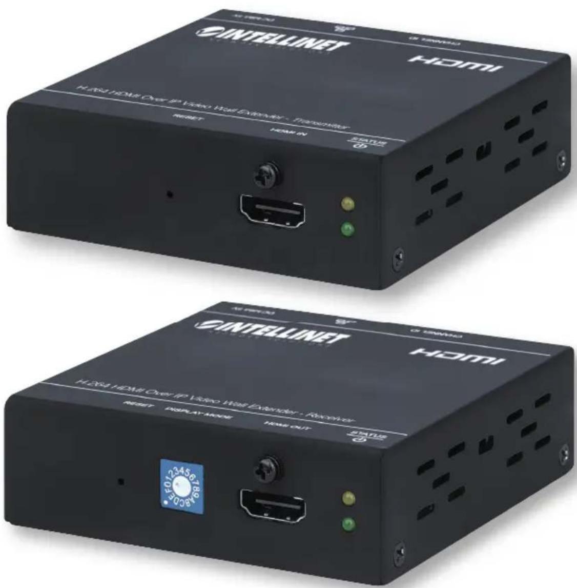
Hardware Features
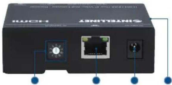
Transmitter

1 Reset
2 HDMI input port with lock
3 LEDs: status (upper, amber); power (lower, green)
4 Channel ID
5 LAN port
6 Power jack
7 Security-lock slot
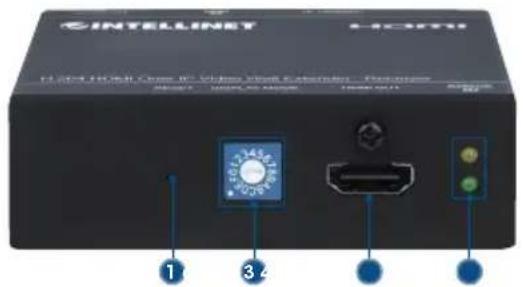
Receiver
natural_image
Front view of a black HCMH device with two ports and connected cables (no visible text or symbols)1 Reset
2 Video display ID
3 HDMI output port with lock
4 LEDs: status (upper, amber); power (lower, green)
5 Channel ID
6 LAN port
7 Power jack
8 Security-lock slot
Installation Guide
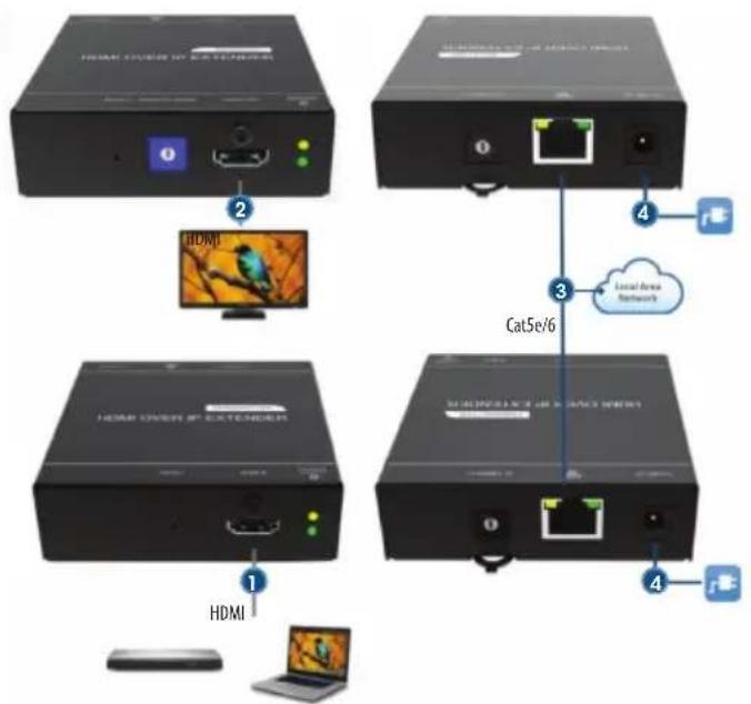
Complete setup with the instructions below. Images for the setups follow in the Connect Devices chapter.
1 Use HDMI cable to connect the HDMI Input port on the Transmitter to the HDMI Output port on your source.
2 Use HDMI cable to connect the HDMI Output port on the Receiver(s) to the HDMI Input port on your display(s).
3 Use Ethernet cable to complete the desired setup:
a Point-to-point: connect the LAN port on the Transmitter to the LAN port on the Receiver or to a network switch (to extend the signal).
b One-to-many and many-to-many: connect the LAN ports on the Transmitter(s) and Receiver(s) to a local area network through a Router and/or Switch hub.
4 Connect each transmitter and receiver to power with the included power adapters.
5 Use the channel-selector tool to match the channel IDs on the Transmitter and Receiver (NOTE: the devices will not connect automatically; they must be matched manually first).
6 To create a video wall, refer to the Video-wall Diagram section. Order your displays accordingly and set the Display ID on the receivers to the corresponding positions.
Connect Devices
Hardware Installation
Point-to-point
- Direct connect from Transmitter to Receiver unit.
• Transmitter unit to network switch to Receiver unit.
One-to-many
• Transmitter unit to an IGMP-snooping-enabled network switch to many Receiver units.
• Transmitter unit to network topology (must support IGMP snooping) to many Receiver units.

flowchart
graph TD
    A["Computer"] --> B["Switch"]
    C["HDMI HDMI"] --> D["Cat5e/6"]
    E["Mac"] --> F["Cat5e/6"]
    G["Desktop"] --> H["Laptop"]
    I["Image of Bird"] --> J["HDMI"]
    style A fill:#f9f,stroke:#333
    style B fill:#ccf,stroke:#333
    style C fill:#ccf,stroke:#333
    style D fill:#cfc,stroke:#333
    style E fill:#cfc,stroke:#333
    style F fill:#cfc,stroke:#333
    style G fill:#cfc,stroke:#333
    style H fill:#fcc,stroke:#333
    style I fill:#fcc,stroke:#333
Many-to-many
• Many Transmitter units to an IGMP-snooping-enabled network switch to many Receiver units
• Many Transmitter units to network topology (must support IGMP snooping) to many Receiver units.

flowchart
graph TD
    A["1 HDMI"] --> B["2 Cat5e/6"]
    C["2 HDMI"] --> D["3 Cat5e/6"]
    E["3 HDMI"] --> F["2 Cat5e/6"]
    G["3 HDMI"] --> H["3 Cat5e/6"]
    I["4 HDMI"] --> J["2 Cat5e/6"]
    K["5 HDMI"] --> L["3 Cat5e/6"]
    M["6 HDMI"] --> N["2 Cat5e/6"]
    O["7 HDMI"] --> P["3 Cat5e/6"]
    Q["8 HDMI"] --> R["2 Cat5e/6"]
    S["9 HDMI"] --> T["3 Cat5e/6"]
    U["10 HDMI"] --> V["2 Cat5e/6"]
    W["11 HDMI"] --> X["3 Cat5e/6"]
    Y["12 HDMI"] --> Z["2 Cat5e/6"]
    AA["13 HDMI"] --> AB["3 Cat5e/6"]
    AC["14 HDMI"] --> AD["2 Cat5e/6"]
    AE["15 HDMI"] --> AF["3 Cat5e/6"]
    AG["16 HDMI"] --> AH["2 Cat5e/6"]
    AI["17 HDMI"] --> AJ["3 Cat5e/6"]
    AK["18 HDMI"] --> AL["2 Cat5e/6"]
    AM["19 HDMI"] --> AN["3 Cat5e/6"]
    AO["20 HDMI"] --> AP["2 Cat5e/6"]
    AQ["21 HDMI"] --> AR["3 Cat5e/6"]
    AS["22 HDMI"] --> AT["2 Cat5e/6"]
    AU["23 HDMI"] --> AV["3 Cat5e/6"]
    AW["24 HDMI"] --> AX["2 Cat5e/6"]
    AY["Max. distance up to 500 m (1,640 ft.) when cascading with four switches"]
Video-wall Diagram
Video-wall Diagram
0
12
3 4 5 6
Display ID
←
←
1
→
7 8 9 A B C D E F
→ → → ↓ ↓ ↓ ↓
VESA Mounting
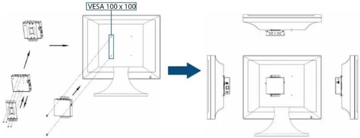
CAUTION! Use only the included power adapters. Using other power adapters may damage your device. IMPORTANT! Use the correct adapter plug for your area/region. This adapter is for dry and indoor uses only.
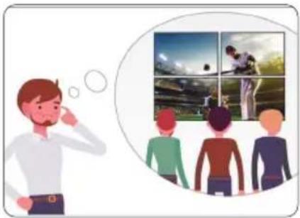
Installation Example
natural_image
Illustration of a man thinking while looking at four inset photos of a football field (no text or symbols)3 Select the TX / RX Channel ID

flowchart
graph TD
    A["Video Source"] --> B["TX"]
    C["Ethernet"] --> B
    B --> D["R1"]
    B --> E["R2"]
    B --> F["R3"]
    B --> G["R4"]
    D --> H["R1"]
    E --> I["R2"]
    F --> J["R3"]
    G --> K["R4"]
    H --> L["R1"]
    I --> M["R2"]
    J --> N["R3"]
    K --> O["R4"]
    L --> P["R1"]
    M --> Q["R2"]
    N --> R["R3"]
    O --> S["R4"]
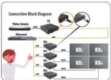
2 You'll need these:1 Want to set up a 2x2 video wall?

4 Select the RX Display ID
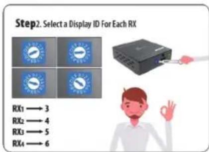
6 Done!5 Device connections

natural_image
Illustration of a man giving thumbs-up with four inset photos of tennis and baseball (no text or symbols)Management UI
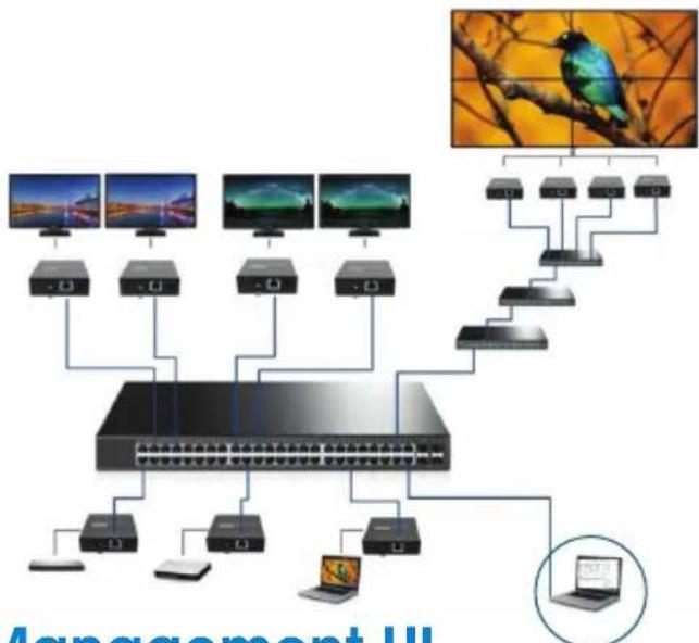
In One-to-many or Many-to-many setups, the transmitters and receivers in the Intellinet Network Solutions H.264 HDMI Over IP Video Wall Extender system can be conveniently managed through a Management User Interface (UI). This UI lets users to create and adjust settings for the connected units, see important information about them, create video walls and more. To log into the UI, use RJ45 cable to connect to the primary network switch for all Transmitter and Receiver devices in the setup. See the example setup that follows.
flowchart
graph TD
    A["Device 1"] --> B["Switch"]
    C["Device 2"] --> B
    D["Device 3"] --> B
    E["Device 4"] --> B
    F["Device 5"] --> B
    G["Device 6"] --> B
    H["Device 7"] --> B
    I["Device 8"] --> B
    J["Device 9"] --> B
    K["Device 10"] --> B
    L["Device 11"] --> B
    M["Device 12"] --> B
    N["Device 13"] --> B
    O["Device 14"] --> B
    P["Device 15"] --> B
    Q["Device 16"] --> B
    R["Device 17"] --> B
    S["Device 18"] --> B
    T["Device 19"] --> B
    U["Device 20"] --> B
    V["Device 21"] --> B
    W["Device 22"] --> B
    X["Device 23"] --> B
    Y["Device 24"] --> B
    Z["Device 25"] --> B
    AA["Device 26"] --> B
    AB["Device 27"] --> B
    AC["Device 28"] --> B
    AD["Device 29"] --> B
    AE["Device 30"] --> B
    AF["Device 31"] --> B
    AG["Device 32"] --> B
    AH["Device 33"] --> B
    AI["Device 34"] --> B
    AJ["Device 35"] --> B
    AK["Device 36"] --> B
    AL["Device 37"] --> B
    AM["Device 38"] --> B
    AN["Device 39"] --> B
    AO["Device 40"] --> B
    AP["Device 41"] --> B
    AQ["Device 42"] --> B
    AR["Device 43"] --> B
    AS["Device 44"] --> B
    AT["Device 45"] --> B
    AU["Device 46"] --> B
    AV["Device 47"] --> B
    AW["Device 48"] --> B
    AX["Device 49"] --> B
    AY["Image: Management III"]
Download the Management UI
Visit the product page at intellinet-network.com/barcode/208338 and click the DOWNLOADS for available downloads. Click the icon titled INTVWEGUI.exe at the folder of the Management UI to launch the program.

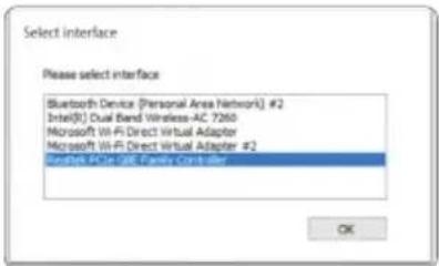
Select Interface
Make sure your computer is on the same local area network and select the network device named Realtek PCIe GBE Family Controller. Click "OK" to continue.
Introduction to the Man agement UI
The management UI includes four pages:
• Device: see the full information of connected Receivers and Transmitters
• Walls: create a new video wall
- Management: select or switch the video source for each created video wall; drag and drop the transmitters listed on the left to the video-wall setup shown on the right
- About: see publisher and UI version
Management UI - Device
See Receiver & Transmitter Information
The page shows the Device name, MAC address, Device ID and State of all Receivers and Transmitters. To edit the Device name, select a Receiver or Transmitter device and click the Edit icon on the top right side of the page.

Advanced Device Settings
Right-click a device for these options: Reboot, Reset to default, Audio On/Off, Show ID and Upgrade firmware. A device goes to the bottom of the list after it is rebooted. Show ID shows the information on the display.


Management UI - Walls
Create New Video Wall
Follow the steps to create a new video wall:
1 Click Create new wall and select the number of Rows and Columns. Then, edit the Wall name.
2 Click Show all receivers ID to easily identify which display is connected to each receiver.
3 Set the displays' positions using receiver IDs. Select and drag a receiver to the desired position.
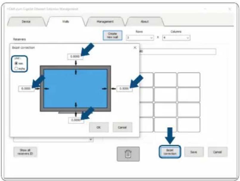
4 Click Bezel correction and select the unit to adjust the widths of each side of the display (i.e., top, bottom, left and right).

Set Display Position
Click Show all receivers ID. Every display screen will show the ID of its connected receiver. Refer to the receivers IDs to select and drag them to the desired positions.
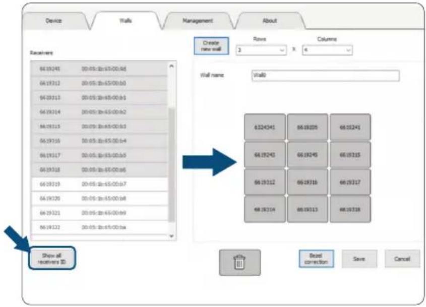
Bezel Correction
Click Bezel correction and select the desired unit to adjust the widths of its right, left, top and bottom sides.
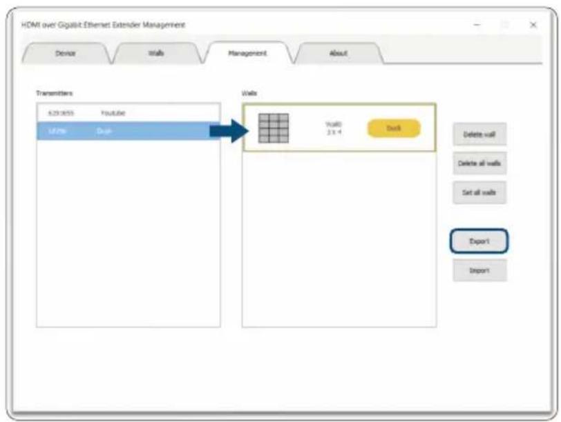
Management UI - Management
Select and drag a Transmitter to the desired wall. Click Export to save the wall configuration. To use this wall in the future, click Import and open the file.

About
See the current version of software or check for new software at the link provided.

Notes
Additional Information
WASTE ELECTRICAL & ELECTRONIC EQUIPMENT
DISPOSAL OF ELECTRIC AND ELECTRONIC EQUIPMENT
(Applicable In The European Union And Other European Countries With Separate Collection Systems)
ENGLISH: This symbol on the product or its packaging means that this product must not be treated as unsorted household waste. In accordance with EU Directive 2012/19/EU on Waste Electrical and Electronic Equipment (WEEE), this electrical product must be disposed of in accordance with the user's local regulations for electrical or electronic waste. Please dispose of this product by returning it to your local point of sale or recycling pickup point in your municipality.
This equipment has been tested and found to comply with the limits for a Class B digital device, pursuant to Part 15 of Federal Communications Commission (FCC) Rules. These limits are designed to provide reasonable protection against harmful interference in a residential installation. This equipment generates, uses and can radiate radio frequency energy, and if not installed and used in accordance with the instructions may cause harmful interference to radio communications. However, there is no guarantee that interference will not occur in a particular installation. If this equipment does cause harmful interference to radio or television reception, which can be determined by turning the equipment off and on, the user is encouraged to try to correct the interference by one or more of the following measures: reorient or relocate the receiving antenna; increase the separation between the equipment and the receiver; connect the equipment to an outlet on a circuit different from the receiver; or consult the dealer or an experienced radio/TV technician for help.
CE
ENGLISH: This device complies with the requirements of CE RED 2014/53/EU, 2014/30/EU and/or 2014/35/EU. The Declaration of Conformity for is available at:
4-F, No. 77, Sec. 1, Xintai 5th Rd.
Xizhi Dist., New Taipei City 221, Taiwan
Europe
IC Intracom Europe Löhbacher Str. 7, D-58553 Halver, Germany
All trademarks and trade names are the property of their respective owners.
All trademarks and trade names are the property of their respective owners.
© IC Intracom. All rights reserved. Intellinet Network Solutions is a trademark of IC Intracom, registered in the U.S. and other countries.
- H.264 HDMI Over IP Video Wall Extender
- User Manual
- CONTENTS
- Introduction
- Setup Components
- Hardware Features
- Transmitter
- Receiver
- Installation Guide
- Connect Devices
- Hardware Installation
- Point-to-point
- One-to-many
- Many-to-many
- Video-wall Diagram
- VESA Mounting
- Installation Example
- Management UI
- Download the Management UI
- Select Interface
- Introduction to the Man agement UI
- Management UI - Device
- See Receiver & Transmitter Information
- Advanced Device Settings
- Management UI - Walls
- Create New Video Wall
- Set Display Position
- Bezel Correction
- Management UI - Management
- About
- Notes
- Additional Information
- WASTE ELECTRICAL & ELECTRONIC EQUIPMENT
- DISPOSAL OF ELECTRIC AND ELECTRONIC EQUIPMENT
- CE
- Europe
Brand : Intellinet
Model : 208338
Category : AV Transmitter