
IDC-1000ZE - Camera SANYO - Free user manual and instructions
Find the device manual for free IDC-1000ZE SANYO in PDF.

| Type de produit | Digital Camera |
| Image Sensor | 2.0 Megapixels (approx.) |
| Optical Zoom | 3x (typical) |
| Digital Zoom | 4x (typical) |
| Display | 1.5-inch LCD |
| Storage Media | SD/MMC card |
| Power Source | 2 x AA batteries (alkaline or rechargeable) |
| Battery Life | Approx. 100 shots (alkaline) |
| Dimensions (W x H x D) | 100 x 60 x 30 mm |
| Weight (without batteries) | 120 g |
| Connectivity | USB 1.1, A/V out |
| Flash Range | 0.5 – 2.0 m |
| Focus Range | 50 cm to infinity (normal mode) |
| White Balance | Auto, Daylight, Cloudy, Fluorescent, Incandescent |
| ISO Sensitivity | Auto, 100, 200, 400 |
| Shutter Speed | 1/1000 – 1 s |
| File Format | JPEG, AVI (motion JPEG) |
| Maintenance | Clean lens with soft cloth; store in dry place |
| Safety Warnings | Avoid exposure to moisture; use only specified batteries |
| Spare Parts Availability | Check with local repair centers |
| Manual Details | Full user manual available online |
Frequently Asked Questions - IDC-1000ZE SANYO
User questions about IDC-1000ZE SANYO
0 question about this device. Answer the ones you know or ask your own.
Ask a new question about this device
Download the instructions for your Camera in PDF format for free! Find your manual IDC-1000ZE - SANYO and take your electronic device back in hand. On this page are published all the documents necessary for the use of your device. IDC-1000ZE by SANYO.
USER MANUAL IDC-1000ZE SANYO
natural_image
White SANYO floppy disk with a silver Ibito logo and printed text (no readable document content)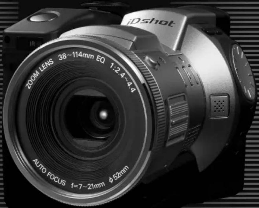
iDshot
iD
PHOTO
This manual explains how to safely operate the IDC-1000ZEX, IDC-1000ZE, and IDC-1000ZU. Any information regarding only one of these products will be labeled as such.
Please read these instructions carefully before using the digital disk camera. Make sure to read and understand the section USING YOUR DIGITAL DISK CAMERA SAFELY AND CORRECTLY from page 5 to 17. Keep this manual in a safe place for later reference.
Caution for laser
Do not open covers and do not repair yourself. Refer servicing to qualified personnel. This product utilizes a laser.
The use, adjustment, or performance of procedures other than those specified herein may result in hazardous radiation exposure.
Laser
Type : Semiconductor laser AlGanP
Output power : 3.5 mW (read-average),
5.85 mW (write-average)
Beam divergence : 45.5 degrees (objective lens emission)
Wavelength : 655 to 666 nm (at 20 to 25°C)
Warning
TO PREVENT THE RISK OF FIRE OR ELECTRIC SHOCK, DO NOT EXPOSE THIS APPLIANCE TO RAIN OR MOISTURE
FOR AMERICAN USERS
This device has been tested and found to comply with the limits for a Class B digital device, pursuant to Part 15 of the FCC Rules. These limits are designed to provide reasonable protection against harmful interference in a residential installation. This device generates, uses, and can radiate radio frequency energy; and, if not installed and used in accordance with the instructions, may cause harmful interference to radio communications. However, there is no guarantee that interference will not occur in a particular installation. If this device does cause harmful interference to radio or television reception, which can be determined by turning the device off and on, the user is encouraged to try to correct the interference by one or more of the following measures:
– Reorient or relocate the receiving antenna.
– Increase the separation between the device and receiver.
- Connect the device to an outlet on a circuit different from that to which the receiver is connected.
- Consult the dealer or an experienced radio/television technician for help.
Changes or modifications not expressly approved by the party responsible for compliance could void the user's authority to operate the device.

Tested To Comply With FCC Standards
FOR HOME OR OFFICE USE
Declaration of Conformity
Model Number : IDC-1000ZU
Trade Name : SANYO
Responsible party : SANYO FISHER COMPANY
Address : 21605 Plummer Street, Chatsworth, California 91311
Telephone No.: (818) 998-7322
This device complies with Part 15 of the FCC Rules. Operation is subject to the following two conditions:
(1) this device may not cause harmful interference, and
(2) this device must accept any interference received, including interference that may cause undesired operation.
FOR CANADIAN USERS
●This Class B digital apparatus complies with Canadian ICES-003.
BEFORE READING THE MANUAL
PowerPC is a registered trademark of International Business Machines Corporation in the United States.
Apple, Macintosh, and QuickTime are registered trademarks of Apple Computer Inc. in the United States.
Windows and Windows NT are registered trademarks in the United States and other countries of Microsoft Corporation in the United States.
Agfa PhotoGenie is a registered trademark in Germany and other countries of Agfa-Gevaert AG in Germany.
The iD PHOTO logo mark is a registered trademark.
All other company and product names are registered trademarks or trademarks of their respective owners.
Regarding the data storage media
- This digital disk camera uses an iD PHOTO disk for data storage. In this manual, the iD PHOTO disk is referred to as “disk.”
Caution
- It is forbidden to copy this manual, whole or in part, without prior written permission.
- All images and illustrations given in this manual are for explanation purposes and may differ slightly from that of the actual product. Also, actual specifications are subject to change without prior notice and therefore may differ from the contents of this manual.
- Sanyo Electric shall not be held responsible for any problems resulting from the use of this digital disk camera.
- Sanyo Electric declines all responsibility for damages due to improper use of the digital disk camera, failure to adhere to the instructions given in this manual, or repairs or changes done by those other than a technician authorized by the manufacturer.
- Sanyo Electric shall not be held responsible for any damage caused by optional devices or consumable items used with the digital disk camera other than those supplied with the digital disk camera or those specified by Sanyo Electric.
- Sanyo Electric shall not be held responsible for any losses or loss of revenue resulting from the loss of data caused by the malfunction, or the repairing of a malfunction, of the digital disk camera.
- The images captured with this digital disk camera will differ in quality from pictures taken with a standard film camera.
Symbols used in this manual
CAUTION Points that require special attention.
NOTE Points giving some extended instructions or operations that require special care.
HINT Points that may prove useful when using the digital disk camera.
HELP In case of problem, this may help in certain situations.

Explanations regarding still images.

Explanations regarding sequential shots.

Explanations regarding video clips.

Explanations regarding audio recordings.
CONTENTS
USING YOUR DIGITAL DISK CAMERA SAFELY AND CORRECTLY.... 5
Preparation
CHECKING THE INCLUDED ACCESSORIES 18
PARTS NAMES....19
POWER SUPPLY 23
INSERTING AND EJECTING THE DISK 30
TURNING THE POWER ON AND OFF 32
SETTING UP AND USING THE REMOTE CONTROL 36
CHECKING THE BATTERY PACK AND DISK 39
SETTING THE DATE AND TIME 42
Recording and playback
BASIC SHOOTING AND PLAYBACK OPERATIONS....46
PLAYING BACK FILES ON A TELEVISION SET 71
Shooting functions
USING THE VARIOUS SHOOTING FUNCTIONS 72
MANUAL MODE SETTINGS....88
Speciality shooting
INTERVAL SHOOTING....98
ANIMATION SHOOTING.... 107
Camera settings
CUSTOM SETTING....112
SETTING THE REMAINING DISK SPACE DISPLAY FORMAT.... 125
Editing
ADDING A VOICE MEMO TO AN IMAGE 127
ADDING AN IMAGE TO ANOTHER IMAGE 130
ENLARGING (ZOOMING IN) THE IMAGE 134
EDITING VIDEO CLIPS.... 136
PROGRAMMED PLAYBACK 141
Disk operations
HANDLING DATA STORED ON THE DISK 147
FORMATTING THE DISK 155
Appendices
USING WITH A COMPUTER SYSTEM 159
TROUBLESHOOTING....162
SPECIFICATIONS....169
USING YOUR DIGITAL DISK CAMERA SAFELY AND CORRECTLY
SAFETY PRECAUTIONS
The following safety precautions are to ensure the safe and correct use of your digital disk camera and prevent injury to the user and others, and property damage. Be sure to read carefully all the precautions listed here before using your digital disk camera.
LI-ION BATTERY PACK (UR-121)
DANGER
Your digital disk camera uses a Li-ion battery pack (part number UR-121).
■If you notice leaking electrolyte, discoloration, deformation, damaged portions, strange odors, or other abnormality, immediately remove from the device, stop use, and move away from any open flames

- If you continue use under these conditions, it may cause a fire, rupturing of the battery pack, eruption of electrolyte, or smoking.
- If electrolyte is leaking and a flame or spark occurs nearby, the electrolyte in the battery pack may ignite causing a fire, rupturing of the battery pack, eruption of electrolyte, or smoking.
■Do not disassemble or modify
●The battery pack is equipped with built-in safety mechanisms and protection devices to prevent dangerous accidents. Disassembling, modifying, soldering, or other similar operations on the battery pack may render these mechanisms or
devices dysfunctional and cause a fire, rupturing of the battery pack, or an eruption or leakage of electrolyte.
■Do not short the positive (+) and negative (-) poles with a metal pin or other object and do not carry or store together with a metal necklace or other object

- If the poles are shorted, a large amount of current will flow, which may cause a fire, rupturing of the battery pack, eruption or leakage of electrolyte, or overheating. Also, the metal object shorting the poles together will become excessively hot. When carrying or storing the battery pack, always place it in the supplied protective cover.
■Do not place in a fire or expose to excessive heat
●The insulation may melt or the gas venting valves and safety mechanisms may fail allowing the electrolyte to ignite and cause a fire or rupturing of the battery pack.

■Do not drop or subject to strong impacts
●Strong impacts may damage the safety mechanisms and protective devices and cause a chemical reaction within the battery pack that may cause a fire, rupturing of the battery pack, eruption or leakage of electrolyte, or overheating.

■Do not submerge in water or wet the terminals
●This will cause corrosion and damage the safety mechanisms and protective devices leading to a chemical reaction within the battery pack that may cause a fire, rupturing of the battery pack, eruption or leakage of electrolyte, or overheating.

■Cautions concerning the locations of use and storage
●Ambient temperature during use or charging: 0 to 40°C
Do not use, recharge, store, or leave near an open flame, in a car under the hot sun, or in any other hot location (60°C or higher).
Extreme heat will damage the safety mechanisms and protective devices and cause a chemical reaction within the battery pack that may cause a fire, rupturing of the battery pack, eruption or leakage of electrolyte, or overheating. If the safety mechanisms and protective devices are damaged, the battery pack will become unusable.
If subject to extremely hot or cold conditions, the capacity of the battery pack will decrease and its usable life will be shortened. Use in ambient temperatures of 20 ± 5^ is recommended. Ambient temperatures below 10^ will cause the operation time to become drastically shortened.
- Ambient temperature during storage: - 20 to 30^ C
When storing the battery pack, remove it from the device, insert it into its protective cover, and store it in a location between -20^ and 30^ .
●Ambient humidity: 45 to 85% RH
■Only recharge using the supplied NC-LSC04WSA AC adapter/charger

- If recharged using a different charger, an excessive charging condition or abnormal electrical currents may result and cause a chemical reaction within the battery
pack. This may cause a fire, rupturing of the battery pack, eruption or leakage of electrolyte, or overheating.
■Only use with the specified devices
- If used with devices not specified for its use, abnormal electrical currents may result and cause a fire, rupturing of the battery pack, eruption or leakage of electrolyte, or overheating.

■Do not remove or damage the covering
- Removing the covering, piercing with a nail, hitting with a hammer, stepping on, or damaging the cover in any way may cause an internal short and result in a fire, rupturing of the battery pack, eruption or leakage of electrolyte, or overheating.

■If you come in contact with electrolyte, immediately rinse with water

- If the electrolyte gets into your eyes, you risk losing your eyesight. Do not rub your eyes, wash them immediately with clean water, and seek medical attention
right away. If electrolyte gets on your skin or clothing, it may cause irritation. Immediately wash with clean water.
■Always insert orientated as indicated
- When inserting the battery pack in the AC adapter/charger or digital disk camera, make sure the positive (+) and negative (−) terminals are oriented correctly as indicated.

- If the battery pack is used or charged with the polarity of the terminals reversed, an abnormal chemical reaction will occur during charging and an abnormal current will flow during use. Both may cause a fire, rupturing of the battery pack, eruption or leakage of electrolyte, or overheating.
WARNING
■If charging is not completed even after the specified time elapses, stop the charging immediately

- If charging is continued, it may cause a fire, rupturing of the battery pack, eruption or leakage of electrolyte, or overheating.

■Keep out of the reach of children
●The battery pack is not a toy and an unforeseeable accident may occur if handled by children.
CAUTION
■Recharge before use
●Always first recharge the battery pack before using it for the first time, or before using it after a long period of non-use. During recharging, the battery pack will be warm. This is normal and does not indicate a malfunction.

■Take care when handling immediately after use
●The battery pack may be extremely hot immediately after use. After turning off the digital disk camera, allow time for the battery pack to cool before removing it.
■Cautions concerning recycling
- To help preserve the environment and promote the effective use of resources, when the battery pack has ended its usable life, completely discharge it, place tape on its positive (+) and negative (−) terminals to prevent shorting, and hand it in for recycling.

- If you must dispose of the battery pack yourself, always dispose of it as nonflammable refuse and follow the regulations for your area.
DIGITAL DISK CAMERA AND AC ADAPTER/CHARGER
WARNING
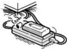
■Do not use the digital disk camera or AC adapter/charger if it makes a strange noise, emits a strange odor, or if smoke comes out from it

- If the digital disk camera or AC adapter/charger is used under these conditions, it may cause a fire or electric shock.
- If any of the above problems occurs, immediately perform the procedures given below and wait to make sure no more smoke is emitted. Then take it to the dealer for service. Do not try to repair the problem yourself.
Digital disk camera
① Turn off the digital disk camera.
② Remove the battery pack. If you are using the AC adapter/charger, remove the power plug from the power outlet.
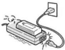
AC adapter/charger
① Remove the power plug from the power outlet.
② If the battery pack is attached, remove it.
■Do not modify or open the cabinet
●High voltage circuits and a laser emitter are inside the digital disk camera, and power supply circuitry is inside the AC adapter/charger. There is a danger of fire or electric shock if they are touched. Also, never disassemble the disk holder because the laser beam may enter your eyes and cause injury. Any internal check, setting, or repair should be performed by the dealer.

■Do not insert metal objects or the like
- Do not insert metal objects inside the devices or short any contacts inside the AC adapter/charger. Doing so may cause a fire or electric shock.

■Do not use while driving

- Do not capture images, play back images, or watch the LCD monitor while driving a vehicle. Doing so may cause an accident.
- Be careful where you put down the digital disk camera or AC adapter/charger inside an automobile. During sudden stops or turns they may fall behind the brake pedal and prevent braking.
- When using the digital disk camera while walking, be very careful of your surroundings and especially the traffic to avoid accidents.
■Be aware of your surroundings during use
●Pay close attention to your surroundings when using the digital disk camera. Failure to do so may lead to an accident or injury.
- Do not use the digital disk camera or AC adapter/charger inside an airplane or elsewhere where use may be restricted.

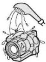
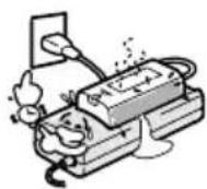
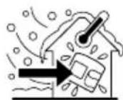
■Do not get the devices wet
●This digital disk camera and AC adapter/charger are not water-resistant. Do not allow them to get wet for doing so may cause a fire or electric shock.
- Do not use in the bathroom or shower.
- If water does get inside the digital disk camera or AC adapter/charger, immediately perform the procedures given below and contact the dealer for service. Do not try to repair the problem yourself.
Digital disk camera
① Turn off the digital disk camera.
② Remove the battery pack. If you are using the AC adapter/charger, remove the power plug from the power outlet.
AC adapter/charger
① Remove the power plug from the power outlet.
② If the battery pack is attached, remove it.
■Do not handle with wet hands
●Handling with wet hands may cause an electric shock.

■Do not use during a storm
●To avoid the risk of being struck by lightning, do not use the digital disk camera or AC adapter/charger during a thunderstorm. In particular, if used in an open field, you have an increased chance of being struck by lightning. Quickly seek refuge in a place that will protect you from lightning.

- Do not touch the AC adapter/charger or power cord while it is plugged into a power outlet during a thunderstorm. Doing so may cause an electric shock.
■Do not place on an unstable surface
●The digital disk camera or AC adapter/charger may fall, resulting in damage or injury. If the digital disk camera or AC adapter/charger has fallen and its body is damaged, turn it off (unplug the power cord, etc.), remove the battery pack, and take it to the dealer for repair. Using the digital disk camera or AC adapter/charger after its body has been damaged may cause a fire or electric shock.

■Do not look into the sun
- Do not look through the digital disk camera at the sun or any other strong source of light. Doing so may seriously injure your eyes or cause blindness.

- Do not use the flash close to a person’s face
- To prevent possible eye injury, do not use the flash near a person's face (especially young children or babies). If the flash is used close to a person's opened eyes, there is a risk that it may damage that person's eyesight.

■Do not use where there is risk of explosion

- Do not use the digital disk camera or AC adapter/charger in a location where there is explosive gas, or any other flammable material in the air. Doing so may cause a fire or an explosion.

natural_image
Illustration of a hand reaching toward a mechanical device with motion lines (no text or symbols)■Keep out of the reach of children
●The following may happen if children play with the digital disk camera or AC adapter/charger:
- They may wrap the strap around their neck and suffocate.
- They may swallow the batteries or other small parts. In such a case, consult a physician immediately.
- They may damage their eyesight if the flash goes off too close to their eyes.
• They may hurt themselves.
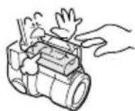
■Only use the specified battery pack and AC adapter/charger

natural_image
Illustration of a hand using a tool to press or install a mechanical component (no text or symbols visible)- Use only the supplied or separately sold UR-121 Li-ion battery pack. Use of a different battery may cause a fire, an electric shock, the batteries to ignite, rupturing of the batteries, or other problem.
- Plug only the supplied AC adapter/charger into the DC IN connector on the digital disk camera. Do not plug in any other device into the DC IN connector. Also, this AC adapter/charger is for exclusive use with this digital disk camera (IDC-1000ZEX, IDC-1000ZE, IDC-1000ZU). Do not use it with any other device.
■Use only to recharge the Sanyo UR-121 Li-ion battery pack

●The supplied AC adapter/charger is for exclusive use with the supplied or separately sold UR-121 Li-ion battery pack. Recharging a dry-cell battery or other type of rechargeable battery may cause excess heat, combustion, or leakage, and cause a fire, injuries, burns, or damage to nearby objects.
■ Do not invert the polarity ((+) and (-)) of the battery pack

- Place the battery pack in the AC adapter/charger with the (+) and (−) terminals oriented as indicated. If the battery pack is placed in the wrong orientation, the batteries may leak, overheat, explode, or be damaged. If the battery pack is charged with the polarity of the terminals reversed, it may cause a fire, rupturing of the battery pack, eruption or leakage of electrolyte, or overheating.
■Use the AC adapter/charger with a 100 to 240 V AC power supply

- If used with a power supply other than that specified, it may cause a fire or electric shock.
■Do not damage the power cord or DC cord of the AC adapter/charger
- Do not place heavy objects on the cords. Do not place the cords near a heat source. Do not excessively bend the cords, modify them, or secure them with staples.
- If a cord is damaged, or if it does not plug properly into the digital disk camera or wall outlet, contact the place of purchase.
■Cautions concerning the power cord
- Do not use the power cord with it wound up. Doing so may cause excessive heat and a fire.
- Do not leave the power cord plugged into the power outlet while the other end is not plugged into the AC adapter/charger. The loose end can cause electrocution if touched with wet hands or if handled by children.
- Only use the power cord supplied with the AC adapter/charger. If a different power cord is used, it may be rated for a different current load, and that may cause a fire.
- The supplied power cord is for exclusive use with the supplied AC adapter/charger. Do not use it with other devices for it may cause a fire or electric shock.
■Unplug the power cord from the power outlet when charging is finished
- If the AC adapter/charger is left plugged into the power outlet for a long period of time, there is a risk of fire.

■Do not pull on power cord to unplug it
- When unplugging the power cord, be sure to hold the power plug and slowly pull it out of the power outlet. Pulling the cord portion may damage the power cord and cause a fire or electric shock.

■Cautions when plugging in the battery charger
- Securely plug the power cord all the way in the power outlet when using the battery charger. If the battery charger is used with the power cord not fully plugged in, heat may generate and cause a fire.
- If the power cord is damaged, or cannot be correctly plugged into the power outlet, do not use the battery charger. Using the battery charger in this condition may cause a fire or electric shock.
- Do not allow dust, etc., to build up on the power cord or power outlet. A build-up of dust may cause a short circuit or generate heat and cause a fire.
CAUTION
■Cautions when carrying the digital disk camera
- Do not walk around with the digital disk camera hanging by the shoulder strap and not properly secured. It may hit other objects, get damaged, or cause an injury.
- Be careful not to drop the digital disk camera or AC adapter/charger or subject them to strong shocks.
- Make sure direct sunlight does not strike the digital disk camera lens or viewfinder, as that may damage the internal parts. When not using the digital disk camera, be sure to always attach the lens cap.
- When packaging or transporting the digital disk camera, be sure to reattach the protective spacer that came with the digital disk camera at the time of purchase (see pages 18, 30).
■Cautions during use and storage
- Your digital disk camera and AC adapter/charger are precision instruments. When using or storing the digital disk camera and AC adapter/charger, make sure to avoid the following locations to avoid damages.
- Places in direct sunlight
- Places near heat generating equipment (stoves, etc.)
- Places with drastic humidity and temperature changes
- Places that may get wet
- Places close to an air conditioner or heater
- Inside a car
- Places where there is dust and dirt
- Places where there is a fire burning
- Places where volatile products are stored
- Places subject to strong electromagnetic fields
- Places subject to vibrations

natural_image
Illustration of a sun, clouds, and a robot-like figure (no text or symbols)Operating environment
Digital disk camera
●Temperature 0 to 35°C (operation) -20 to 60°C (storage)
●Humidity 30 to 90% (operation, no condensation) 10 to 90% (storage, no condensation)
AC adapter/charger
- Temperature 0 to 35^ (operation) -20 to 60^ (storage)
● Humidity 45 to 85% (operation, no condensation) 45 to 85% (storage, no condensation)
- When connecting the digital disk camera and AC adapter/charger, make sure the cords are not caught on any objects.
■Do not cover with a cover, rug, or similar object
- Covering with a cover, rug, or similar object will cause the internal heat to rise and may cause a fire.

■Be aware that internal temperatures rise during use
- Be aware that the internal temperatures of the digital disk camera and AC adapter/charger will rise and may become hot to touch during use. Contact while hot for an extended period of time may cause light burns.

CAUTION
■Do not connect the AC adapter/charger to an electronic transformer
- Connecting the AC adapter/charger to an electronic transformer will cause a malfunction and possibly a fire.
■Cautions if the digital disk camera or AC adapter/charger is not going to be used for a long period
- For safety, remove the battery pack. The battery pack may generate heat or leak, and that may start a fire, cause injuries or burns, and damage any objects placed nearby. When the battery pack is removed for a long period, the date and time settings will be retained for approximately one year (or until the internal backup battery runs out).


natural_image
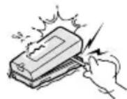
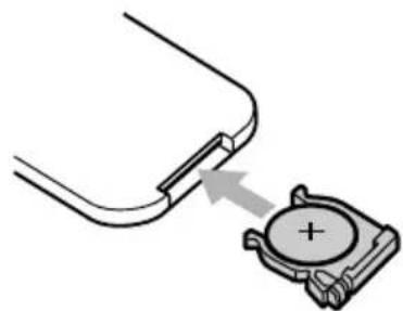
Cartoon illustration of a camera with a sleeping face and a rectangular base, no text or symbols presentCONCERNING THE LITHIUM BATTERY CR2025
WARNING
■Cautions concerning the battery CR2025
●One lithium battery CR2025 is used for the remote control and one is used for backing up the internal clock. Do not use a battery other than the lithium battery CR2025.
- Install the battery with the (+) and (−) terminals oriented as indicated. If the battery is placed in the wrong orientation, it may cause a fire, overheating, or rupturing.

natural_image
Cartoon illustration of a person heating with a sun and steam rising nearby (no text or symbols)- Do not recharge, short circuit, disassemble, modify, heat, or place the battery in a fire. Doing so may cause a fire, overheating, or rupturing.
- Do not hold the battery with metal tweezers or a similar tool. Doing so may cause a short circuit leading to a fire, overheating, or rupturing.
- Do not perform soldering on the battery or use, store, or leave it near a fire, under direct sunlight, in a hot car, or other high temperature location.
- Do not use the battery if it is leaking.
- If the electrolyte gets into your eyes, you risk losing your eyesight. Do not rub your eyes, wash them immediately with clean water, and seek medical attention right away. If electrolyte gets on your skin or clothing, it may cause irritation. Immediately wash with clean water.
- Keep the battery out of the reach of children. If the battery is accidentally swallowed, contact a physician immediately. It may cause poisoning or suffocation.
- When disposing of batteries, make sure to follow all applicable regulations.
- When disposing of the lithium battery, place tape on its positive (+) and negative (−) terminals to prevent shorting. Do not mix the lithium battery with other batteries. Doing so may cause a fire or rupturing.
INSTRUCTIONS FOR THE PROPER USE OF YOUR DIGITAL DISK CAMERA
■Cautions before capturing important images
- Before capturing important images, make sure that the digital disk camera is operating properly and in condition to capture the image properly.
- Sanyo Electric shall not be held responsible for any losses that result from images that could not be recorded, are erased, destroyed, or damaged in any way due to a problem with the digital disk camera, any of its accessories, or its software.
■Cautions concerning copyrights
●The images you capture with your digital disk camera are for your own private use, any other use may violate the rights of copyrights owners.
■Cautions when cleaning the digital disk camera and AC adapter/charger
Cleaning procedure
① Turn off the digital disk camera and remove the battery pack. (If the AC adapter/charger is connected, unplug its power cord.)
② Remove the dirt with a soft cloth.
③ If the digital disk camera is extremely dirty, wipe with a soft cloth moistened with a mild detergent diluted with water and wrung dry.
Caution
- Do not use benzene or thinner products to clean the digital disk camera or AC adapter/charger. Doing so may cause deformation, discoloration, or paint peeling. When using a chemically treated cloth, carefully read its instructions and warnings.
- Do not spray insecticides, or volatile sprays on the digital disk camera or AC adapter/charger. Do not leave rubber or vinyl objects against the digital disk camera or AC adapter/charger for a long period. They may cause deformation, discoloration, or paint peeling.
■Cautions when cleaning the lens
- If the lens gets dirty, use a commercially available air blower or a cleaning cloth for photographic equipment to clean it.
●It is also possible to clean the viewfinder (see page 166).
■Cautions concerning the battery pack terminals
- Periodically clean with a dry cloth the terminals of the battery pack, digital disk camera, and AC adapter/charger.
- Do not touch the terminals with your bare hands. Doing so will allow contaminants from your hands to adhere to the terminals and oxidize, increasing the contact resistance. If the contact resistance increases, the usable life of the battery pack will diminish and recharging may become impossible.
■Cautions when not using the digital disk camera
- Attach the lens cap whenever you are not using the digital disk camera.
When not using the digital disk camera for a long period
- Remove the battery pack. However, when the battery pack is removed for a long time, the digital disk camera functions may begin to not work properly. Periodically reinstall the battery pack and check the digital disk camera functions.
- If the battery pack is left in the digital disk camera, a small amount of power is still used even if the digital disk camera is turned off. If the battery pack is left in the digital disk camera for a long period, it may become completely discharged and loose its ability to be recharged again.
■Cautions concerning condensation
- Using the digital disk camera with condensation inside it may damage the digital disk camera.
Be careful of condensation under the following conditions
- When moving the digital disk camera suddenly from a cold place to a warm place.
- When the ambient temperature changes drastically, such as when a heater is turned on to quickly heat the room.
- When the digital disk camera is placed in the path of cool air from an air conditioner.
- When the digital disk camera is placed in a location of high humidity.
If condensation seems likely to form
- Place the digital disk camera in a plastic bag and seal it, and then wait until the digital disk camera has reached the ambient temperature.
■Cautions concerning undesired interference
- The digital disk camera or AC adapter/charger may create undesired interference if used close to a television or radio. To reduce the amount of undesired interference emitted, cores are attached to the supplied AV cable and the DC cord of the AC adapter/charger. Do not remove these cores. Also, when using the supplied microphone or IEEE1394 cable, attach one of the supplied cores as shown below.
Supplied AV cable
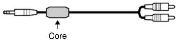
Supplied AC adapter/charger
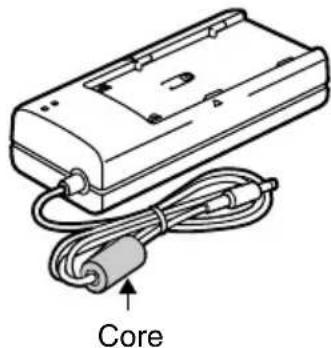
natural_image
Line drawing of a device with a Core cable and connector (no text or symbols on the diagram itself)When using the supplied microphone or IEEE1394 cable
- Attach a supplied core as shown below.
① Make a loop in the cord just behind the plug.
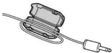
natural_image
Illustration of a mechanical device with a coiled cable and connector (no text or symbols)Ferrite core (small)

② Close the core.
- Be careful not to pinch the cord with the core when closing the core.
■Cautions concerning magnetism
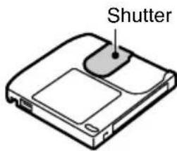
- Do not place credit cards, bankcards, floppy disks, or other items that may be damaged by magnetic fields near the speaker. Data may be lost or the magnetic strips on cards may be damaged.

■ Cautions concerning the iD PHOTO disk
- The iD PHOTO disk is provided for use with devices displaying the iD PHOTO logo mark for the storage and playback of image data. Do not use with devices that do not display the iD PHOTO logo mark for doing so may cause damage to the device and the disk.
- The iD PHOTO disk is a precision device. Do not bend, drop, or subject it to strong forces or shocks.
- Do not open the shutter and touch the iD PHOTO disk inside.
- Immediately after use, the iD PHOTO disk may be very hot. Before removing the iD PHOTO disk, turn off the digital disk camera and wait until the disk cools.
- Keep out of the reach of children. Children may put the disk in their mouths or perform some other unforeseeable action.

Cautions when handling the iD PHOTO disk
- Avoid storing or using the iD PHOTO disk in places similar to those given below for they may cause damage or the disk to malfunction.
- Places in direct sunlight or near heat generating equipment
- Places extremely cold
- Places with excessive dust, dirt, or humidity
- Places subject to vibrations
- Places with drastic humidity and temperature changes
- Places with excessive static electricity or electromagnetic noise
- Do not place the iD PHOTO disk near magnets or in strong magnetic fields.
- Do not disassemble the iD PHOTO disk.
- Do not allow the iD PHOTO disk to get wet.
- Wipe away dust or dirt with a soft, dry cloth. Do not use benzene, thinner, or other solvents.
- Do not use in locations with drastic temperature changes or in locations with a high humidity. These locations are subject to condensation. If condensation occurs in the iD PHOTO disk, reading from and writing to the disk may become impossible.
- Before using an iD PHOTO disk for the first time, be sure to format it with your digital disk camera first (see pages 155, 157).
- Before capturing important images, it is recommended to first try capturing images to make sure that the digital disk camera works properly. Also, to further ensure that images are captured properly, perform a full format beforehand (see page 157).
- Attach the labels carefully so that they will not come off accidentally. If the label comes off during insertion or removal of the iD PHOTO disk from the digital disk camera, it may cause damage (see page 18).
- Do not allow dirt or other foreign particles to enter the shutter portion of the iD PHOTO disk. Wipe away any dirt with a soft, dry cloth. Do not use benzene, thinner, or other solvents.


Cautions when carrying or storing the iD PHOTO disk
● Always remove the iD PHOTO disk from the digital disk camera after you have finished using it.
- When not using the iD PHOTO disk, always keep it in its protective case.
- Do not carry the iD PHOTO disk inside trouser pockets, as it may become damaged when you sit down or make other movements that may apply forces.
Making sure that data on your iD PHOTO disk does not become erased
Move the write-protect tab to the "O-m" mark.
- Move the tab using a sharp item such as the end of a ballpoint pen.
- Saving (adding data such as capturing images or recording), deleting, and formatting will become impossible.
- To make it possible to perform saving, deleting, and formatting again, move the tab back to its original position.
| Write protected | Write enabled |
■Cautions concerning data storage
- The iD PHOTO disk is a highly reliable storage device, however it is recommended that any important data be copied onto a separate media (such as a floppy disk, hard disk, or MO disk) for added safety against unforeseeable accidents.
- Stored data may be lost (or corrupted) in cases such as those listed below. Sanyo Electric will not be held responsible for any damage or lost profits arising from the loss of data.
- If the iD PHOTO disk is used incorrectly.
- If the iD PHOTO disk is not inserted correctly into the digital disk camera.
- If the iD PHOTO disk is subjected to electrical or mechanical shocks or other forces.
- If the iD PHOTO disk is removed from the digital disk camera or if the digital disk camera is turned off during reading or writing operations.
- If the iD PHOTO disk has reached the end of its usable life.
■Cautions concerning vibrations
- If the digital disk camera is subject to vibrations or shocks during image capturing or the playing back of data, the data may not be properly read or written. Therefore always be careful not subject the digital disk camera to vibrations or shocks during use.
■Cautions concerning rises in temperature
- During use, ☑ or ⚙ may appear to tell you that the internal temperature of the digital disk camera is rising. If this occurs, stop operations and turn off the digital disk camera as soon as possible. See pages 167 and 168 for further information.

natural_image
Plain gray background with a small white square in the top-left corner (no text or symbols)Rising temperature mark

High temperature mark
CHECKING THE INCLUDED ACCESSORIES
Open the box and check that all the accessories listed below are included. If a part listed here is not present or damaged, contact the place of purchase.
The page numbers listed next to the part names are the page numbers where that part is explained in detail.
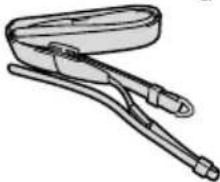
- Grip belt [page 48]

natural_image
Illustration of a medical or laboratory device with a handle and bulb (no text or symbols)● Shoulder belt [page 48]
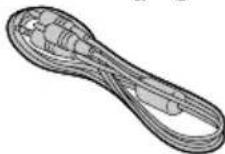
natural_image
Line drawing of a coiled cable or clamp device with two connectors (no text or symbols)- AV cable [page 71]
●Battery pack and protective cover (Li-ion battery pack UR-121) [pages 24, 27]
●AC adapter/charger and power cord
(NC-LSC04WSA) [pages 24, 29]

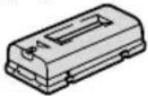
natural_image
Illustration of a rectangular electronic device with two cables and connectors (no text or symbols)●Remote control [pages 22, 36] (Lithium battery is installed at the time of purchase.)

- iD PHOTO disk, protective case, labels (730 MB: DSM-D730A) [pages 30, 155]
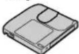
●Protective spacer [page 30] (Located inside disk holder at the time of purchase. Use to transport the digital disk camera.)
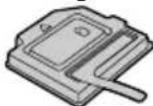
●Lens cap [page 12]

Press here to attach and remove the lens cap.
Attaching the labels


●Lithium battery for clock backup (CR2025) [page 23]

- Core [page 15]

Protective caseID PHOTO disk
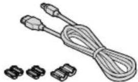
- USB interface cable - IEEE1394 interface cable
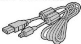
and 3 cores
natural_image
Illustration of a coiled cable with two connectors and three separate connector pins (no text or symbols)●Software: 3 CD-ROMs

natural_image
Three identical circular discs arranged horizontally (no text or symbols)●Scart adapter (for IDC-1000ZE only)
Use this adapter to connect an AV cable to a television or VCR equipped with the EURO-AV type audio/video input terminal.

●Microphone [page 49]

PARTS NAMES
Front
The page numbers listed next to the part names are the page numbers where that part is explained in detail.

①F1 button [pages 55, 84]
②F2 button [pages 55, 85]
③ Control dial [pages 52, 66, 87]
④ RETURN button [pages 55, 87]
⑤ Microphone [page 79]
⑥ W.BAL (white balance) button [page 96]
⑦ EXP (exposure) button [page 92]
⑧FOCUS button [page 90]
⑨ Zoom switch [page 74]
⑩ Lens [page 14]
⑪ Remote control sensor [page 36]
⑫ Self-timer lamp [pages 36, 81]
⑬ Shutter release button [pages 35, 51]
⑭ Flash [page 76] (Press the flash pop-up button to stand up the flash bulb.)

⑮ Flash pop-up button [page 76]
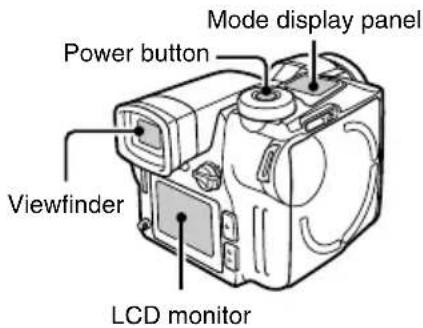
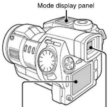
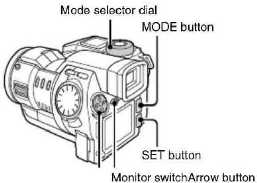
Rear
The page numbers listed next to the part names are the page numbers where that part is explained in detail.

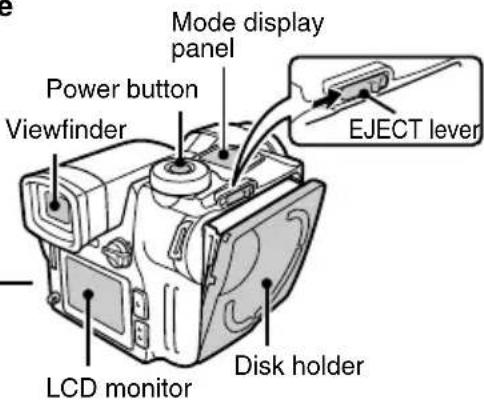
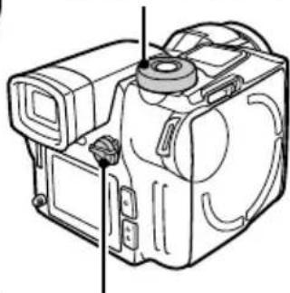
① Mode display panel [pages 32, 39, 41]
② Mode selector dial [page 47]
③ Grip belt holder [page 48]
④ Viewfinder [pages 32, 50]
⑤Monitor switch [page 32]
⑥Arrow button [page 52]
⑦ AUTO/MAN button [page 89]
⑧ Shoulder belt holder [page 48]
⑨ Terminal cover [pages 29, 49, 71]
⑩ MIC (microphone) input terminal [pages 49, 68]
⑪ AV output terminal [page 71]
⑫ DC IN (external DC power input) terminal [page 29]
⑬ Speaker [page 16]
⑭ Focus ring [page 90]
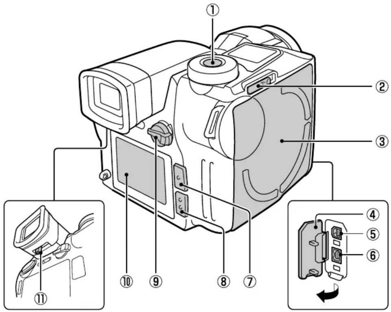
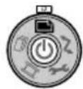
① Power button [pages 32, 35]
②EJECT lever [pages 30, 31]
③ Disk holder [pages 30, 31]
④ Interface cover [page 159]
⑤USB terminal [page 159]
⑥ IEEE1394 terminal [page 160]
⑦ MODE button [pages 43, 54]
⑧ SET button [pages 43, 54]
⑨ CAMERA/PLAY switch [page 47]
⑩ LCD monitor [pages 32, 50]
⑪ Diopter adjustment lever [page 33]
Bottom
The page numbers listed next to the part names are the page numbers where that part is explained in detail.

① Tripod stand hole [page 80]
② Grip belt holder [page 48]
③ BATT (battery cover release) knob [pages 23, 27]
④ Battery pack cover [pages 23, 27]
⑤Battery pack mating area [page 27]
⑥Clock backup battery cover [page 23]
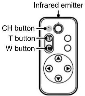
Remote control
The page numbers listed next to the part names are the page numbers where that part is explained in detail.
Excluding the CH button, all buttons perform the same operation as the button of the same name on the digital disk camera itself.
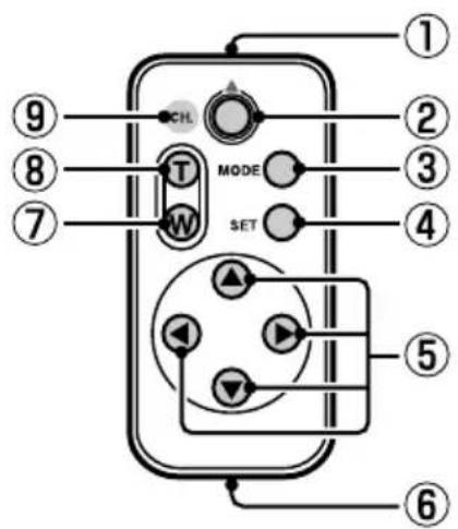
① Infrared emitter [page 36]
② Shutter release button [page 51]
③ MODE button [page 54]
④ SET button [page 54]
⑤Arrow button [page 52]
⑥ Battery holder [page 37]
⑦W (zoom wide) button [pages 38, 74]
⑧T (zoom telescopic) button [pages 38, 74]
⑨CH button [page 38]
POWER SUPPLY
Use only the UR-121 battery pack with your digital disk camera. To operate the digital disk camera using a power outlet, use the supplied AC adapter/charger.
Your digital disk camera can be operated using two different types of power supplies:
●The supplied battery pack [pages 24 to 28]
- The supplied AC adapter/charger (using the AC power supply from an AC power outlet) [page 29]
Caution
- Use only the supplied or separately sold UR-121 battery pack. Use of another battery pack may damage the digital disk camera.
- The supplied or separately sold UR-121 battery pack is for the exclusive use with this digital disk camera. Use with a different camera may cause a fire or electric shock.
Installing the clock backup battery
Follow the procedure below to install the battery for backing up the date and time settings, various camera settings, and other disk information. The backup lithium battery will last approximately one year and then will require replacement (one CR2025 battery).
1
Open the battery pack cover.
① Press and hold down the BATT knob on the digital disk camera bottom.
② Pull the battery pack cover toward the front of the digital disk camera and then lift it up.

2
Open the clock backup battery cover and install the clock backup battery.
●The clock backup battery (CR2025) is installed in the bottom of the section for the battery pack.
●Wipe the battery clean with a soft, dry cloth and then install it with the positive (+) terminal facing upward.

flowchart
graph TD
    A["Start"] --> B["Clock backup battery cover"]
    B --> C{Cycle 1}
    C --> D["Cycle 2"]
    D --> E{Cycle 3}
    E --> F["Cycle 4"]
    F --> G["End"]
NOTE
Saving the camera settings
- Whether a fully charged battery pack is installed, a clock backup battery is installed, or AC power is used with the AC adapter/charger, the manual mode settings and other camera settings will be saved even when the digital disk camera is turned off. However, when 📄 is selected at the hold settings menu, the settings are not saved and are returned to their initial settings (see page 112).
Charging the battery pack
The battery pack is not charged at the time of purchase and therefore needs to be charged before use. Always use the supplied AC adapter/charger to recharge the battery pack.
Follow the procedure below to charge the supplied battery pack or a new UR-121 battery pack used for the first time, or to recharge a battery pack that has become low in charge.
1 Remove the protective cover from the battery pack.
2 Insert the battery pack into the AC adapter/charger.
① Orient the battery pack as shown in the figure on the right, align the ▲ marks on the sides of the battery pack and AC adapter/charger, and insert the battery pack in the AC adapter/charger.
② Push in the direction of the arrow.
3 Insert the supplied power cord into the socket on the AC adapter/charger.
- Insert the power cord straight and until it is fully seated.
4 Plug the power cord into a power outlet (AC 100 to 240 V).
●Charging will start automatically.
●During charging, the BATTERY CHARGE lamp will light red.
●Charging will take approximately 120 minutes.
- When charging is completed, the BATTERY CHARGE lamp will turn off.


BATTERY CHARGE lamp (red)
NOTE
- Recharge the battery pack just before use or on the day before use. If charged and left unused, the charge will slowly leak reducing the time the battery pack can be used.
- Avoid storing the battery pack with it near full charge. It is recommended to store the battery pack when it is near fully discharged.
- If the battery pack is completely discharged, it may become unable to be recharged again. To avoid this, charge the battery pack for at least five minutes every six months.
5 When the BATTERY CHARGE lamp turns off, unplug the power cord from the wall outlet.
6 Remove the battery pack from the AC adapter/charger.
- If you are not going to attach the battery pack to the digital disk camera right away, then place it in its protective cover.

NOTE
- You can use the digital disk camera with the AC power supply even while charging (see page 29). In this situation, charging is stopped automatically and AC power is supplied to the digital disk camera. When the digital disk camera is turned off, charging is resumed.
- During charging, the battery pack and AC adapter/charger will become warm. This is not a malfunction.
If noise is received by a radio or television during charging
●Perform the charging in a location away from the radio or television.
Ambient temperature during charging
- The ambient temperature during charging should be kept between 10 and 35^ . If the temperature drops below 10^ , the characteristics of the battery pack may not allow it to become fully charged.
Recharge the battery pack before use in the situations given below
- If the battery pack has not been used for a long period of time.
- If the battery pack is new and is being used for the first time.
The BATTERY CHARGE and AC ADAPTER lamps
The BATTERY CHARGE and AC ADAPTER lamps allow you to check the condition of the battery pack and AC adapter/charger. If either of the lamps begins flashing, it indicates a problem. Refer to the table below to check and remedy the problem.
| BATTERY CHARGE lamp | Off Power is not being supplied | |
| On Charging | ||
| Flashing There is a | problem with the battery pack | |
| Immediately remove the battery pack. | ||
| Do not use a malfunctioning battery pack (the battery pack has likely ended its usable life). | ||
| AC ADAPTER lamp | Off The AC adapter/charger is not connected properly | |
| On AC power is being supplied to the digital disk camera | ||
| Flashing There is a | problem with the AC adapter/charger | |
| Immediately unplug the power cord from the power outlet. | ||
| Do not charge the battery pack. | ||
| Contact the place of purchase. | ||
HELP
If the BATTERY CHARGE lamp does not turn off
- If more than 150 minutes have elapsed since charging was begun and the BATTERY CHARGE lamp does not turn off, there is a malfunction. If this occurs, immediately stop charging and contact the place of purchase.
Installing the battery pack
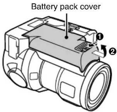
1 Open the battery pack cover.
① Press and hold down the BATT knob on the digital disk camera bottom.
② Pull the battery pack cover toward the front of the digital disk camera and then lift it up.
Battery pack cover

2 Attach the charged battery pack to the battery pack mating area.
① Orient the battery pack as shown in the figure below, align the edges of the battery pack and the battery pack mating area, and insert the battery pack in the battery pack mating area.
② Push in the direction of the arrow.

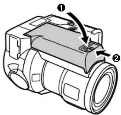
3 Close the battery pack cover.
① Close the battery pack cover.
② Push it towards the back of the digital disk camera until it is secured in place.
Removing the battery pack
Caution
- Before removing the battery pack, be sure to turn off the digital disk camera. Removing the battery pack while the power is still on may damage the digital disk camera or data on the disk.
1 If the digital disk camera is turned on, turn it off (see page 35).
- Press the power button for more than one second.
- When the power is turned off, the displays on the mode display panel and LCD monitor (or viewfinder) turn off.
2 Open the battery pack cover.
① Press and hold down the BATT knob on the digital disk camera bottom.
② Pull the battery pack cover toward the front of the digital disk camera and then lift it up.
3 Remove the battery pack.
- Slide the battery pack toward the front of the digital disk camera and lift it upward. (Be careful not to drop the battery pack when removing it.)
- Immediately after use, wait a few minutes before removing the battery pack because it may still be hot.
natural_image
Technical line drawing of a camera module with no visible text or symbols4 Close the battery pack cover.
Using the AC power supply
Use the supplied AC adapter/charger to operate the digital disk camera with an AC power supply (by connecting to a power outlet).
Caution
- The AC adapter/charger is for exclusive use with this digital disk camera (IDC-1000ZEX, IDC-1000ZE, IDC-1000ZU). Do not use it with any other device.
- If the AC ADAPTER lamp is flashing, there is likely a problem with the AC adapter/charger. If it is flashing, immediately unplug the power cord from the power outlet and contact the place of purchase (see page 26).
1 Insert the supplied power cord into the socket on the AC adapter/charger.
- Insert the power cord straight and until it is fully seated.
2 Plug the DC cord into the DC IN terminal on the digital disk camera.
3 Plug the power cord into a power outlet (AC 100 to 240 V).
4 Turn on the digital disk camera (see page 32).
- When the digital disk camera is turned on, the green AC ADAPTER lamp turns on.
- If charging is being performed at this time, charging is stopped automatically and AC power is supplied to the digital disk camera. (The red BATTERY CHARGE lamp turns off and the green AC ADAPTER lamp turns on.)

INSERTING AND EJECTING THE DISK
Be sure to insert the disk before using the digital disk camera. Use only iD PHOTO disks with the iD PHOTO logo mark (iD). No other type of disk can be used with this digital disk camera (IDC-1000ZEX, IDC-1000ZE, IDC-1000ZU). Also, before using the supplied disk or any other disk for the first time, always format it first with your digital disk camera (see pages 155, 157).
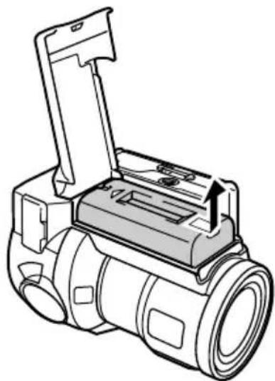
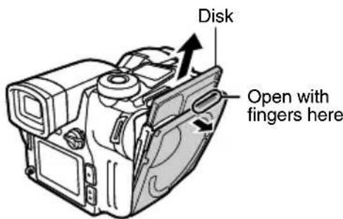
Inserting the disk
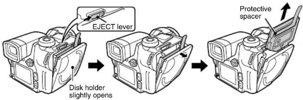
1 Push the EJECT lever in the direction of the arrow.
- The disk holder opens slightly. Gently open the disk holder in the direction of the arrow given below.
- A protective spacer is placed inside the disk holder at the time of purchase. Remove this spacer if it is present.
2 Insert the disk into the disk holder.
- Insert the disk in the direction of the arrow given (▼ mark) with its label facing outwards.
- Be sure to insert the disk all the way in until it is properly seated.

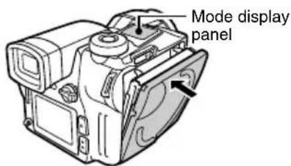
3 Push the disk holder closed.
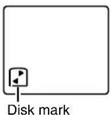
- When the disk is inserted, the disk mark in the mode display panel lights.
NOTE
If the disk mark turns
●The disk mark in the mode display panel rotates when a disk is inserted. While the mark is rotating, data on the disk is being read and recording cannot be performed. Wait until the disk mark stops rotating before using the digital disk camera. (The digital disk camera can be turned on while the disk mark is rotating.)
Ejecting the disk
Caution
Be careful not to let the disk fall
- Depending on how you are holding the digital disk camera, when the disk is ejected, it may fall out of the digital disk camera and become damaged. When ejecting the disk, be careful not to let the disk fall from the disk holder.
1 If the digital disk camera is turned on, turn it off (see page 35).
- Press the power button for more than one second.
- When the power is turned off, the displays on the mode display panel and LCD monitor (or viewfinder) turn off.
2 Push the EJECT lever in the direction of the arrow.
●The disk holder opens slightly.
3 Open the disk holder in the direction of the arrow.
- When the disk holder is opened, the disk is ejected.
4 Gently pull out the disk.
HELP
If the disk cannot be removed
- If data on the disk is being accessed (the disk mark is rotating; see page 30), the disk holder will not open when the EJECT lever is pushed. Wait until the disk mark stops rotating and the digital disk camera turns off.
- If the digital disk camera is on, the disk cannot be removed. Turn off the digital disk camera and then eject the disk with the EJECT lever.
●The disk can be removed in the power save mode (see page 35). - If the disk cannot be removed when the digital disk camera is off, turn the digital disk camera back on and then off again, and then eject the disk with the EJECT lever.
Turning on the digital disk camera
Preparation
●Prepare the power supply (see pages 27, 29).
1 Insert the disk (see page 30).
●The digital disk camera cannot be turned on if a disk is not inserted.
2 Press the power button for more than one second.
●The digital disk camera does not turn on right away to prevent it from being turned on accidentally.
●The mode display panel turns on.
●The display on the viewfinder or LCD monitor turns on.
- If the AC adapter/charger is connected and AC power is supplied, the AC ADAPTER lamp will light (see page 29).

NOTE
Changing the monitor
- The image composed by the digital disk camera can be displayed in either the viewfinder or the LCD monitor. For the sake of brevity, the term “monitor” is often used alone in this manual to refer to either one. For example, “select the monitor” means for you to select either the LCD monitor or viewfinder. Before capturing or playing back images, it will be necessary for you to select the monitor.
To show the display in the viewfinder, move the monitor switch to "FINDER"
- The display in the LCD monitor turns off.
- If the image in the viewfinder is out of focus, use the diopter adjustment lever below the viewfinder to adjust it (see page 21).

To show the display in the LCD monitor, move the monitor switch to "MONITOR"
- The display in the viewfinder turns off.
HELP
If the timer mark (☐) in the mode display panel is flashing
- This is warning you that the date and time have not been set. Once the date and time are set, this mark will stop flashing (see page 42).
NOTE
About the disk status display
- Once the power is turned on, the status of the disk may appear in the monitor.
If "PROTECTED" appears
- This indicates that the write-protect tab of the disk has been moved to the “O—” mark (see page 155).
If "DISK FULL" appears
- This indicates that there is no more space on the disk.
If "REFORMAT?" appears
- This indicates that the disk has not been formatted (see page 155).
If "NO FILE" appears
- This indicates that no files for the current playback mode can be found (see page 34).
What to do if "NO FILE" appears
When "NO FILE" appears it indicates that no files for the current playback mode can be found.
If "DISK : EMPTY" appears, then there are no files stored on the disk. Switching the CAMERA/PLAY switch to "CAMERA" brings up the shooting screen.
If "DISK : NOT EMPTY" appears, then there are other files stored on the disk. To play back those files, perform the operations given below.
Switch the playback mode
① Turn the mode dial to ☐, ☐, or ☒.
- The selected mode is entered and if files for that mode are present, the playback screen appears.
- If audio recordings are present, see "Playing back audio recordings" on page 69.
- If no files are found and "DISK : NOT EMPTY" still appears, perform the operations given in "Switch folders" below.
Switch folders
① Press the SET button.
- "SKIP FILE" appears. (The Skip File Screen)
② Turn the control dial to select a folder number.
- If an image appears, press the RETURN button to exit the Skip File Screen.
- If you turn the control dial and the folder number does not change, then there are no other folders.

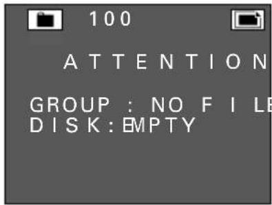
When the disk is empty

When data is present of a different type or in a different folder

Skip File Screen
NOTE
- Temporary video clip interval files (see page 106) and temporary animation files (see page 111) are not considered video clip files and therefore the "NO FILE" message will appear even if they are present. Be aware of this when erasing data or reformatting the disk.
HINT
- When you want to know the types of files or folder numbers present, see "Viewing the folder information" on page 118. Knowing the types of files present and the number of folders helps when playing back files.
Turning off the digital disk camera
1 Press the power button for more than one second.
●The digital disk camera does not turn off right away to prevent it from being turned off accidentally.
- When the power is turned off, the displays on the mode display panel and LCD monitor (or viewfinder) turn off.

Turning on the digital disk camera from the power save mode
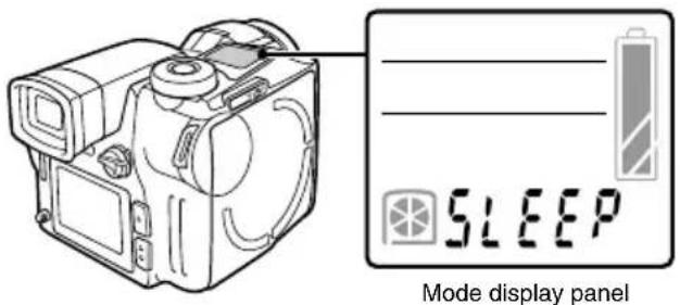
In order to prevent the battery pack from being used when not necessary, if the power is turned on and no operation is performed for a certain amount of time (three minutes in the shooting mode, five minutes in the playback mode, and thirty minutes when the AC adapter/charger is connected), your digital disk camera is equipped with a power save function that activates and automatically puts the digital disk camera in the power save mode. However, if the remote control menu (see page 124) at the Option Screen is set to 📄 (not using remote control), the digital disk camera will be turned off without going into the power save mode.
About the power save mode
When the digital disk camera enters the power save mode, "SLEEP" appears in the mode display panel.
●The power can be turned back on with the remote control when in the power save mode.
- If the power save mode is continued for two hours, the power is turned completely off.
- If the disk is ejected in the power save mode, the power is turned off automatically.
Turning the power back on
1 Press the shutter release button or power button.
●This method is the same for the shooting and playback modes.

NOTE
- You can connect the digital disk camera to your personal computer and set the time before the power save function activates to the time you desire. For more details, refer to the instruction manual supplied with the SANYO Software Pack.
SETTING UP AND USING THE REMOTE CONTROL
Setting up the remote control
A battery is installed in the remote control at the time of purchase.
1
Pull out the battery insulation sheet.
- Once the battery insulation sheet is removed, the remote control is ready for use.
natural_image
Diagram of a device with ports and an arrow indicating direction (no text or symbols)Battery insulation sheet
2
Perform the remote control setting at the digital disk camera (see page 124).
●The remote control setting must be set properly in order to use the remote control to operate the digital disk camera.
- At the time of purchase, the digital disk camera is already set so that the remote control can be used.
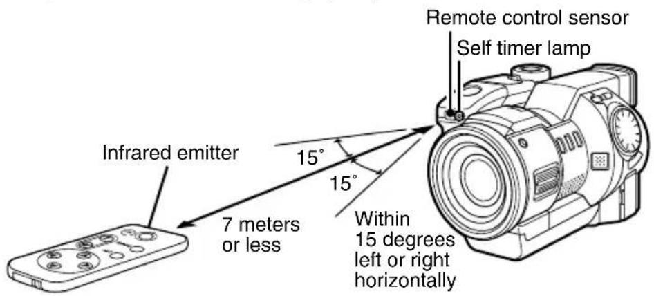
Using the remote control
The remote control must be used within a seven-meter distance from the remote control sensor, between 15 degrees to the left and right on the horizontal. If there is an obstruction between the remote control and its remote control sensor, it may block the signal and prevent operation of the digital disk camera by the remote control. If this is the case, remove the obstruction.
- Each button on the remote control performs the same operation as the button of the same name on the digital disk camera (see page 22).
- When an operation is performed with the remote control, the self-timer lamp lights for one second to signal that the signal has been received.
- If the remote control is located to the front and right of the digital disk camera, the digital disk camera lens may block its signal. If this is the case, change your position.
NOTE
- The signal range of the remote control may be decreased if used under bright sunlight or inverted lighting. This is a characteristic of infrared remote controls and not a malfunction. To reduce problems during use, do not allow such light to enter the remote control sensor.
Replacing the remote control battery
The life of the lithium battery will depend on your use of the remote control, but as a general guideline, it will require replacement approximately once a year. At that time replace it only with the commercially available CR2025 lithium battery.
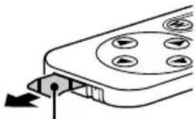
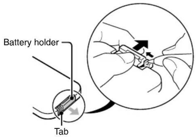
1 Pull out the battery holder.
- Push in the tab to release the battery holder and then pull it out.
2 Remove the battery.

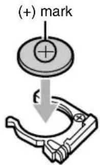
3 Insert the new battery (CR2025).
●Wipe the new battery with a soft, dry cloth and then insert it with the (+) mark facing upward.
4 Push in the battery holder.
natural_image
Diagram showing a connector with a positive charge symbol inside a battery (no text or labels)Changing the remote control code
This remote control will also work with other Sanyo cameras that can be operated by infrared remote control. Therefore, when more than one camera is present, it is recommended to change the remote control code to ensure that only the intended camera operates when the remote control is used. The remote control code is set to "1" at the time of purchase.
Changing the remote control code from "1" to "2"
1 Aim the infrared emitter at the remote control sensor on the digital disk camera.
2 Hold down the CH button and press the W button for more than three seconds.
- The self-timer lamp lights for one second when the remote control code changes to "2." Release the buttons on the remote control.

3 Press a button on the remote control and check that the operation was carried out correctly.
- The remote control code is not lost even if you replace the battery in the remote control.
- If the remote control codes for the remote control and digital disk camera do not match, operations will not be carried out.
Returning the remote control code to "1"
1 Aim the infrared emitter at the remote control sensor on the digital disk camera.
2 Hold down the CH button and press the T button for more than three seconds.
- The self-timer lamp lights for one second when the remote control code returns to "1." Release the buttons on the remote control.
CHECKING THE BATTERY PACK AND DISK
You can check the remaining charge in the battery pack and the remaining space on the disk with the LCD monitor, viewfinder, or mode display panel. Be sure to always check these values before using the digital disk camera to prevent problems.
LCD monitor Viewfinder
Checking the battery pack
1 Install the battery pack (see page 27).
2 Turn on the digital disk camera (see page 32).
●The remaining charge in the battery pack is displayed in the mode display panel.
- When the battery pack becomes low on charge, the remaining amount will also be displayed in the LCD monitor or viewfinder.
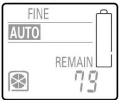
Mode display panel

natural_image
Simple gray background with a small white battery icon in the bottom right corner (no text or symbols)LCD monitor (or viewfinder)
Display of remaining charge
| Indicator | Remaining charge of battery pack | |
| Mode display panel | LCD monitor or viewfinder | |
 | No indication A | Approximately full charge. |
 | No indication B | Battery pack charge is low. |
 | No indication | It will soon be impossible to capture or playback images. The remaining charge is not sufficient to accept commands from a computer connected (see page 159) using the SANYO Software Pack. |
 | ||
 |  | Replace with a fully charged battery pack. |

LCD monitor Viewfinder
NOTE
- The amount of time a fully charged battery pack will last will depend on factors such as your use of the flash, your use of the LCD monitor, the ambient temperature, and other shooting conditions. For ambient temperatures below 10°C, the rate the charge decreases is especially fast. Therefore, even the same battery pack may allow different number of images to be captured under different conditions.
- Before using the digital disk camera for important situations (e.g. wedding or when traveling) or in cold environments, it is recommended to take a spare battery pack with you as a precaution.
- For ambient temperatures below 10°C, it is recommended to keep the battery pack warm by placing it in your pocket or some other warm location.
HELP
If the LCD monitor goes off suddenly
- When using the LCD monitor with the battery pack charge about half full, the LCD monitor may turn off momentarily after an image is captured. This is to allow a quick recharge of the flash. When the flash has been recharged, the LCD monitor will come back on automatically.
Checking the remaining disk space
1 Insert the disk (see page 30).
2 Turn on the digital disk camera (see page 32).
●The remaining space in the disk is displayed in the mode display panel.
- The remaining disk space is shown in one of three ways. See “Setting the remaining disk space display format” on page 125 to set the way you want it to be displayed.
- For more information on the remaining number of images and recording time, see page 172.
Display in mode display panel
●Remaining number of images/remaining recording time available
Depending on the current shooting mode, either the remaining number of images or the remaining recording time available will be displayed.

Remaining number of images that can be captured

Remaining recording time available (hrs:min:sec)
●Remaining percentage of disk space
The remaining percentage of disk space available is displayed.

Remaining percentage
●Remaining disk space
The remaining disk space in megabytes is displayed.
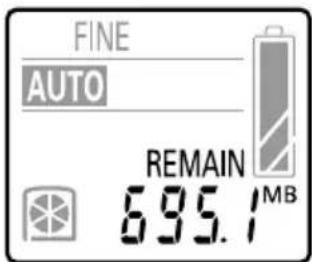
Remaining disk space (MB)
SETTING THE DATE AND TIME
Your digital disk camera is equipped with a clock function that will record the date and time that any image, video clip, or audio recording is made so that it can be displayed during playback. An internal battery backs up the clock setting so that it is retained even when the battery pack is removed.
Caution
- Even if the battery pack is removed and the digital disk camera is not connected to an AC power supply, the clock setting will be retained by an internal backup battery (see page 23). However, if this is continued for a long period of time, this battery will lose its charge and the clock and other camera settings will return to their initial settings (00:00, January 1, 2001). If you have not used your digital disk camera for a long time, make sure to first check the clock setting.
- When the clock setting is in its initial setting, the timer mark (①) in the mode display panel will flash. When the clock is set, the mark will disappear (see page 33).
Setting the clock
Preparation
- Insert a disk (see page 30).
●Turn the power on (see page 32).
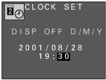
Example: Setting the clock to 7:30 p.m., August 28, 2001.
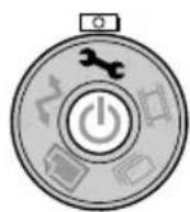
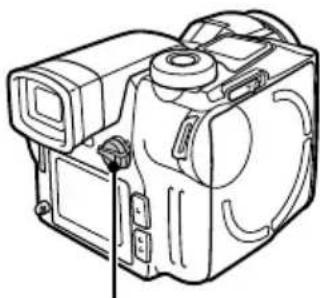
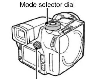
1 Turn the mode selector dial to (3c) to display the option screen.
2 Set the monitor switch to "MONITOR."
●The Option Screen appears in the LCD monitor.


Date and time setting icon Option Screen
3 Press the arrow to select the date and time setting icon ☑ and press the SET button.
●The Date and Time Setting Screen appears with the current date and time settings.
●The setting of whether or not to display the date and time at playback is displayed in orange.
- To set whether or not to display the date and time at playback, the date format, or the date and time, proceed to the operations given below.

Date and Time Setting Screen
Operation of buttons at the Date and Time Setting Screen
Arrow button
Change a setting: Press ▲ or ▼
Select the next item: Press ▶
Select the previous item: Press ◀
Other buttons
Cancel the procedure and return to the Option Screen: Press the MODE button
Enter the new settings and return to the Option Screen: Press the SET button
4 Set whether or not to display the date and time at playback.
① Press ▲ or ▼ to select "ON" or "OFF."
To display the date and time : Select ON
To not display the date and time : Select OFF
- To set the date format or the date and time, continue to the operations given below.

5 Set the date format.
① Press ▶ to select the date format.
• The date format turns orange.
② Press ▲ or ▼ to select the desired date format.
• Each time ▼ is pressed, the date format changes as shown below.

Year/month/day: Y/M/D
Month/day/year: M/D/Y
Day/month/year: D/M/Y
• Each time ▲ is pressed, the date format changes in reverse.

6
Set the date and time (the clock setting).
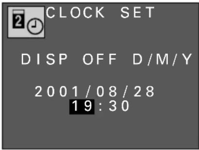
① Press ▶ to select the year setting.
- The year setting turns orange.
② Using the arrow button, change the setting to 7:30 p.m., August 28, 2001.
- The hour is set with a 24-hour clock. Therefore 7:30 p.m. is "19:30."
Arrow button
Decrease setting by one: Press ▲ once
Increase setting by one: Press ▼ once
Select the next item: Press ▶
Select the previous item: Press ◀
7
Press the SET button.
●The clock starts at the set time and you return to the Option Screen.
- You can set the clock accurately by listening to an official time recording and pressing the SET button at the exact time.

Option Screen
Changing the date and time setting
1 Perform steps 1 to 3 on page 42 and press the ◀ or ▶ on the arrow button to select the item to be changed.
2 Press ▲ or ▼ on the arrow button to change the setting to the desired value.
- To change another item, press ◀ or ▶ to select the other item and change it as desired.

3 Press the SET button.
●This completes the change of the date and time.
BASIC SHOOTING AND PLAYBACK OPERATIONS
Setting the mode
Your digital disk camera is equipped with a number of modes. The shooting mode and the playback mode are two of them and they both have still image, sequential shot, and video clip modes. Your digital disk camera is also equipped with the option mode for setting the clock, making audio recording, and performing other functions.
Switching between the shooting and playback modes
To capture images or record video clips, use the shooting mode, and to view images or play back video clips, use the playback mode.
Preparation
- Insert a disk (see page 30).
●Turn the power on (see page 32).
1 Set the CAMERA/PLAY switch to "CAMERA" or "PLAY."
For shooting mode: Set to "CAMERA"
For playback mode: Set to "PLAY"
natural_image
Line drawing of a mechanical device with ports and mounting brackets (no text or symbols)CAMERA/PLAY switch

Shooting mode

Playback mode
Changing the mode
Preparation
- Insert a disk (see page 30).
●Turn the power on (see page 32). - Set the CAMERA/PLAY switch (see page 46).
1 Turn the mode selector dial to the icon of the desired mode.
For still image mode: Set to
For sequential shot mode: Set to 📄
For video clip mode: Set to 📄
For option mode: Set to ↗
For PC connection mode: Set to ↗
CAMERA/PLAY switch
About the modes
| Mode | CAMERA/PLAY switch | Mode selector dial | |
| Shooting mode | Still image shooting mode | CAMERA (shooting mode) |  |
| Sequential shot shooting mode | |||
| Video clip shooting mode | [KXBD] | ||
| Playback mode | Still image playback mode | PLAY ( playback mode) |  |
| Sequential shot playback mode |  | ||
| Video clip playback mode | [92DT] | ||
| Option mode | CAMERA or PLAY (select either shooting or playback mode) | [9CAH] | |
| PC connection mode |  | ||
Attaching the grip belt and shoulder belt
Before using your digital disk camera, be sure to attach the grip belt. The shoulder belt is useful for carrying the digital disk camera over your shoulder or hanging it from your neck.
Attaching the grip belt

Attaching the shoulder belt
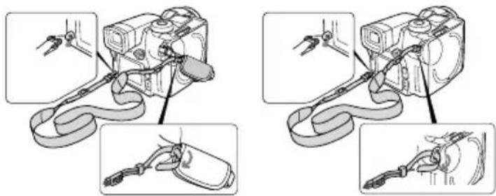
natural_image
Illustration of a mechanical device with attached wires and accessories, shown in two different states (no text or symbols present)Proper use of your digital disk camera
In order to capture the image you are aiming at properly, it is very important that you are holding the digital disk camera correctly with the correct posture. Be sure to always hold the digital disk camera steadily and make sure that the shoulder strap, your finger, or any other object is not in front of the lens.
As shown in the figures below, hold the digital disk camera steady with both hands and keep your elbows in toward your sides.
Horizontal shooting Vertical shooting Bad example

- When using the flash (see page 76), make sure that your fingers or other objects do not get in the way of the flash.
Using the supplied microphone
In addition to the built-in microphone, you can also use the supplied external microphone to make audio recording when using your digital disk camera. Place the microphone according to the scene that you are recording (see pages 62, 68, 79). The microphone can also be used together with the grip belt as shown below.

Capturing and playing back still images
Capturing still images
Preparation
- Insert a disk (see page 30).
●Turn the power on (see page 32).
1 Put the digital disk camera in the still image shooting mode.
- Set the CAMERA/PLAY switch to "CAMERA."
- Turn the mode selector dial to 📄.
- If necessary, set the resolution (see page 84) and compression ratio (see page 85) as desired.
Mode selector dial
natural_image
Line drawing of a mechanical device with no visible text or symbolsCAMERA/PLAY switch

2 Select which monitor to use and compose the image.
- You can compose the image by looking through the viewfinder or by looking at the LCD monitor.
Using the viewfinder
① Set the monitor switch to "FINDER."
- The image is displayed in the viewfinder and the LCD monitor turns off.
- If the image in the viewfinder is out of focus, use the diopter adjustment lever below the viewfinder to adjust it (see page 21).
② Look straight into the viewfinder and center the subject.
Using the LCD monitor
① Set the monitor switch to "MONITOR."
- The image is displayed in the LCD monitor and the viewfinder turns off.
② Point the digital disk camera at the subject and center the subject in the LCD monitor.

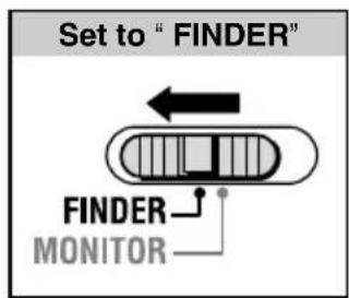
Monitor switch
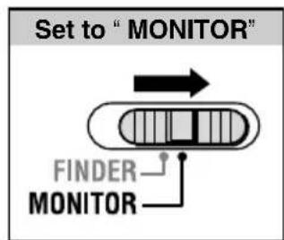
Monitor switch
3
Press the shutter release button.
- Your digital disk camera is equipped with an autofocus function. The autofocus function works as explained below.
① Press the shutter release button halfway (focus lock).
- The autofocus function activates and puts the subject in focus.
- If ▲ is selected for the shutter sound (see page 119), a beep will sound when the focus locks.
- When the focus locks, the focus icon (♦), shutter speed setting, and aperture setting appear in the monitor.
② Gently press the shutter release button all the way.
- The shutter is released and the image is captured.
- If ▲ is selected for the shutter sound (see page 119), the set shutter sound will be heard when the shutter is released (a camera clicking sound is set at the time of purchase).
- You can keep the shutter release button depressed and view the captured image in the monitor.
- When you release the shutter release button, the clock icon 📋 appears in the monitor signifying that the image is being saved. During this time, images cannot be captured. When the clock icon 📋 disappears, the digital disk camera is ready to capture the next image.
- To view the image you captured, set the CAMERA/PLAY switch to PLAY.
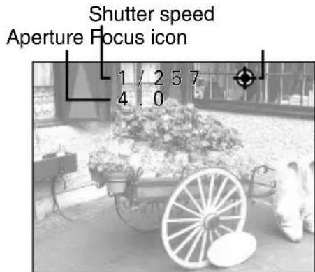

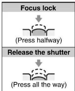
flowchart
graph TD
    A["Focus lock"] --> B["(Press halfway)"]
    C["Release the shutter"] --> D["(Press all the way)"]
NOTE
- If you are using the remote control to capture images, you cannot use the autofocus function.
Playing back still images
Preparation
- Insert a disk (see page 30).
●Turn the power on (see page 32).
1 Put the digital disk camera in the still image playback mode.
- Set the CAMERA/PLAY switch to "PLAY."
- Turn the mode selector dial to 📄.
●A captured still image appears in the viewfinder or LCD monitor.
2 Press ◀ or ▶ on the arrow button to select the image you want to view.
To display the previous image: Press ◀
To display the next image: Press ▶
Using the control dial
To display the previous image: Turn counterclockwise To display the next image: Turn clockwise
- If an image has a voice memo (see pages 78, 127) attached to it, the volume icon 📋 appears in the Playback Setting Screen (step 2 on page 54). To listen to the voice memo, first exit the Playback Setting Screen and then press the SET button.
- To adjust the playback volume, see "Adjusting the volume" on page 70.

Mode selector dial

natural_image
Line drawing of a mechanical device with no visible text or symbolsCAMERA/PLAY switch

MODE button

Control dial

Useful playback features for still images
Preparation
- Insert a disk (see page 30).
●Turn the power on (see page 32).
Consecutive playback
Follow the procedure below to play back images consecutively one after the other.
1 Put the digital disk camera in the still image playback mode.
- Set the CAMERA/PLAY switch to "PLAY."
- Turn the mode selector dial to 📄.
●A captured still image appears in the viewfinder or LCD monitor.
2 Press and hold ◀ or ▶ on the arrow button.
- Images are displayed one after the other while the arrow button is pressed down.
Automatic playback (slide show)
Follow the procedure below to play back images automatically in order in a slide show fashion. If voice memos (see pages 78, 127) are attached, they will be heard also.
1 Put the digital disk camera in the still image playback mode.
- Set the CAMERA/PLAY switch to "PLAY."
- Turn the mode selector dial to 📄.
●A captured still image appears in the viewfinder or LCD monitor.
2 Press and hold ▲ or ▼ on the arrow button until "SLIDE SHOW" appears.
- "SLIDE SHOW" appears in the monitor and automatic playback begins to display each image one after the other, each for about 4 seconds.
For automatic playback in order saved: Press ▼
For automatic playback in reverse order saved: Press ▲

3 To stop the automatic playback, press the arrow button.
- "SLIDE SHOW OFF" appears and automatic playback stops.
- You can also press the MODE or SET buttons to stop the automatic playback.

NOTE
- If the Playback Setting Screen (step 2 on page 54) or the Skip File Screen (step 2 on page 55) appears before step 2 for automatic playback (slide show), then automatic playback cannot be performed. If this occurs, first press the MODE button to exit the Playback Setting Screen or the Skip File Screen, and then continue with step 2.
HELP
If "NO FILE" appears
- There are no files for the currently selected playback mode. To check the type of files stored in the disk or the folder number, see "Viewing the folder information" on page 118. To find an image, see page 34. If "DISK : EMPTY" appears, there are no files in the disk.
9-image display playback
Follow the procedure below to display nine images captured in the still image shooting mode in the monitor at one time.
1 Put the digital disk camera in the still image playback mode.
- Set the CAMERA/PLAY switch to "PLAY."
- Turn the mode selector dial to 📄.
●A captured still image appears in the viewfinder or LCD monitor.
2 Press the MODE button to display the Playback Setting Screen.
- The 9-image playback icon is selected initially.
9-image playback icon
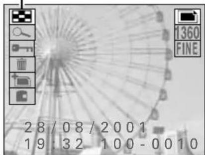
Playback Setting Screen
3 Press the SET button.
●The 9-image Playback Screen for still images appears.
●The number shown on each image is the image number for that image.
4 Press the arrow button to move the ✏ mark to the image you want to view and press the SET button.
●The selected image is displayed full screen.
- You can also move the ➕ mark by turning the control dial.

9-image Playback Screen
HELP
If ? appears in the 9-image display
- ? may be displayed if the images were saved on the disk using a different digital disk camera.
If an image number is missing
- An image number is the actual file name for that image and it does not change. Therefore, if an image is erased (see page 149), other image numbers will not change to fill the open space and it may seem that an image number is missing. For example, if image number 0005 in the image above is erased, then the image numbers that will appear are 0001 through 0004 and 0006 through 0010.
Specific image number playback
Follow the procedure below to specify the image number of the image that you want to view.
1 Put the digital disk camera in the still image playback mode.
- Set the CAMERA/PLAY switch to "PLAY."
- Turn the mode selector dial to 📄.
●A captured still image appears in the viewfinder or LCD monitor.
2 Press the F2 button.
●The Skip File Screen appears.
●To change the folder from which to play back images, press the F1 button, turn the control dial to select the folder number, and press the RETURN button.

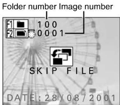
Skip File Screen
3 Turn the control dial to select the image number of the image that you want to view.
●After a few moments, the selected image is displayed full screen.
4 Press the RETURN button.
●The Skip File Screen disappears.
Capturing and playing back sequential shots
Capturing sequential shots
Preparation
- Insert a disk (see page 30).
●Turn the power on (see page 32).
1
Put the digital disk camera in the sequential shot shooting mode.
- Set the CAMERA/PLAY switch to "CAMERA."
●Turn the mode selector dial to 📄. - If necessary, set the resolution (see page 84), compression ratio (see page 85), and the sequential shot method (standard or AE shift) (see page 82) as desired.
2
Select which monitor to use and compose the image.
- You can compose the image by looking through the viewfinder or by looking at the LCD monitor. See step 2 on page 50.

Shutter release button
Mode selector dial
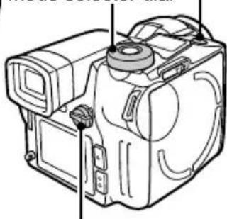
natural_image
Line drawing of a mechanical device with no visible text or symbolsCAMERA/PLAY switch
3
Press the shutter release button.
- For how to focus, see step 3 on page 51.
●The sequential shot begins when you press the shutter release button. - For information on how many images are captured, see page 172.
●While the sequential shot images are being captured, the REC icon will appear in the monitor. - When the REC icon disappears from the monitor, the sequential shot is finished.
- When you release the shutter release button, the clock icon 📋 appears in the monitor signifying that the images are being saved. During this time, sequential shots cannot be captured. When the clock icon 📋 disappears, the digital disk camera is ready to capture the next sequential shot.
- To view the sequential shot you captured, set the CAMERA/PLAY switch to "PLAY."
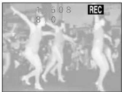
HELP
If the clock icon 📋 appears after the sequential shot and the disk mark ✪ appears rotating continuously in the mode display panel
- After a disk has been used (saving and deleting data) over and over again, the data stored on the disk becomes fragmented and the saving and playing back of images may take a longer time than normal. If the data storage sectors on the disk have become drastically fragmented, then the storage of a sequential shot may take a very long time. Wait until the clock icon 📁 and disk mark ✪ disappear.
Playing back sequential shots
Preparation
- Insert a disk (see page 30).
●Turn the power on (see page 32).
1 Put the digital disk camera in the sequential shot playback mode.
- Set the CAMERA/PLAY switch to "PLAY."
●Turn the mode selector dial to 📄.
●The 9-image Playback Screen for sequential shots appears.
●All the images of each sequential shot are grouped together and stored in a folder exclusively for that sequential shot. The 9-image Playback Screen shows the first image of each of these sequential shot folders.
2 Press the arrow button to move the ➕ mark to the sequential shot you want to view and press the SET button.
●The first image of the selected sequential shot is displayed full screen.
- You can also move the ➕ mark by turning the control dial.


9-image Playback Screen

natural_image
Black-and-white photo of a group of people dancing or performing in a public indoor setting (no visible text or symbols)HINT
To quickly display a different sequential shot
- After step 2, with the Playback Setting Screen not displayed, press ▲ or ▼ to change to the previous or following sequential shot respectively.
3 Press ◀ or ▶ on the arrow button to view the images of the sequential shot.
To display the previous image: Press ◀
To display the next image: Press ▶
Using the control dial
To display the previous image: Turn counterclockwise
To display the next image: Turn clockwise
- To view a different sequential shot, proceed to steps 4 through 6.
4 Press the MODE button.
●The Playback Setting Screen appears.
- The 9-image playback icon is selected.
5 Press the SET button.
●The 9-image Playback Screen appears.
6 Press the arrow button to move the ➕ mark to the sequential shot you want to view and press the SET button.
●The first image of the selected sequential shot is displayed full screen.
- You can also move the ➕ mark by turning the control dial.

natural_image
Black-and-white photo of a naval vessel and a smaller boat on a ship deck, no visible text or symbols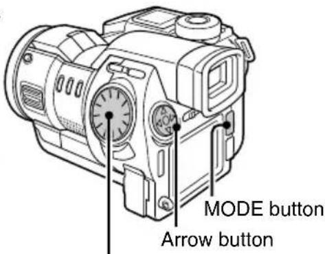
Control dial

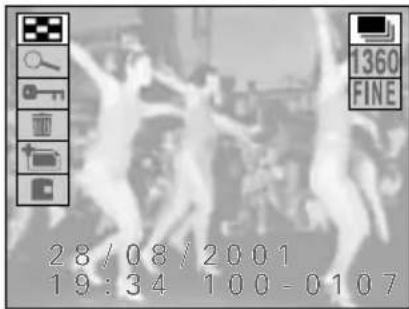
Playback Setting Screen
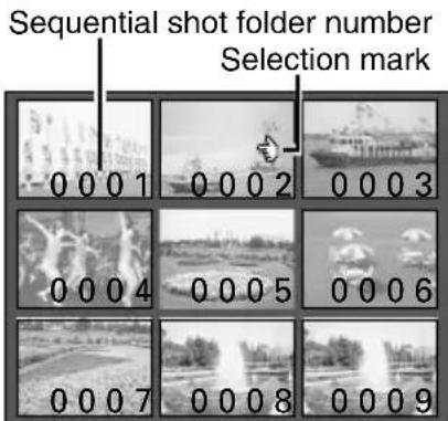
9-image Playback Screen
HELP
If ? appears in the 9-image display
- ? may be displayed if the sequential shots were saved on the disk using a different digital disk camera.
If a sequential shot folder number is missing
- A sequential shot folder number is the actual folder name for that sequential shot folder and it does not change. Therefore, if a sequential shot folder is erased (see page 149), other sequential shot folder numbers will not change to fill the open space and it may seem that a sequential shot folder number is missing. For example, if sequential shot folder number 0005 in the image above is erased, then the sequential shot folder numbers that will appear are 0001 through 0004 and 0006 through 0010.
Useful playback features for sequential shots
Preparation
- Insert a disk (see page 30).
●Turn the power on (see page 32).
Consecutive playback
Follow the procedure below to play back sequential shots consecutively one after the other.
1 Put the digital disk camera in the sequential shot playback mode.
- Set the CAMERA/PLAY switch to "PLAY."
●Turn the mode selector dial to 📄.
●The 9-image Playback Screen for sequential shots appears. Press the arrow button to move the 🔊 mark to the sequential shot you want to view and press the SET button.

2 Press and hold ◀ or ▶ on the arrow button.
●Images of the selected sequential shot are displayed one after the other while the arrow button is pressed down.
- Consecutive playback in the sequential shot playback mode only displays the images for one sequential shot (i.e. the images in one sequential shot folder).

natural_image
Technical line drawing of an electric motor with labeled arrow button (no other text or symbols)NOTE
To play back images from more than one sequential shot folder
- To view images from different sequential shots, you must either copy the images so that they can be handled as still images (see page 153) and perform the consecutive playback on the still images or program the playback (see page 141).
Specific sequential shot folder number playback
Follow the procedure below to specify the sequential shot folder number of the sequential shot that you want to view.
1 Put the digital disk camera in the sequential shot playback mode.
- Set the CAMERA/PLAY switch to "PLAY."
●Turn the mode selector dial to 📄.
●The 9-image Playback Screen for sequential shots appears. Press the arrow button to move the 🔊 mark to the sequential shot you want to view and press the SET button.
2 Press the F2 button.
●The Skip File Screen appears.
- To change the folder from which to play back sequential shots, press the F1 button, turn the control dial to select the folder number, and press the RETURN button.
3 Turn the control dial to select the sequential shot folder number of the sequential shot that you want to view.
●After a few moments, the first image of the selected sequential shot is displayed full screen.
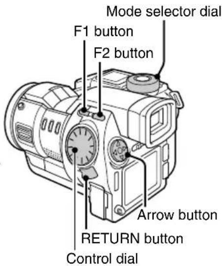

Skip File Screen
4 Press the RETURN button.
●The Skip File Screen disappears.
5 Press ◀ or ▶ on the arrow button to view the images of the sequential shot.
- You can also display the different images using the control dial.
HINT
To quickly display a different sequential shot
- After step 1, press ▲ or ▼ to change to the previous or following sequential shot respectively. See “HINT” on page 57.
Recording and playing back video clips
Recording video clips
Preparation
- Insert a disk (see page 30).
●Turn the power on (see page 32).
1
Put the digital disk camera in the video clip shooting mode.
- Set the CAMERA/PLAY switch to "CAMERA."
●Turn the mode selector dial to 📄. - If necessary, set the resolution (see page 84) and frame rate (see page 86) as desired.
2
Select which monitor to use and compose the image.
- You can compose the image by looking through the viewfinder or by looking at the LCD monitor. See step 2 on page 50.

Shutter release button Mode display panel Mode selector dial
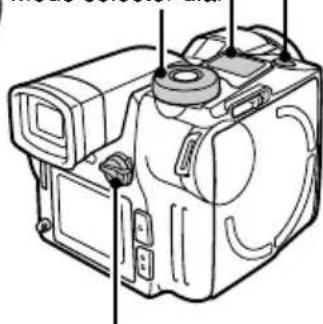
natural_image
Technical line drawing of a mechanical device housing with mounting brackets and internal components (no text or symbols)
CAMERA/PLAY switch
3
Press the shutter release button.
- For how to focus, see step 3 on page 51.
●The video clip (video and audio recording) begins when you press the shutter release button. - While the video clip is being recorded, the REC icon will appear in the monitor.
- By having the mode display panel show the remaining recording time available for the disk, you can check the remaining amount of time available (see page 125).

natural_image
Close-up of a metallic fan structure with internal grid lines and circular components (no text or symbols visible)4
Press the shutter release button again to stop recording.
● Recording stops and the REC icon disappears.
- When you stop recording, the clock icon 📋 appears in the monitor signifying that the video clip is being stored. During this time, video clips cannot be recorded. When the clock icon 📋 disappears, the digital disk camera is ready to record the next video clip.
- To view the video clip you recorded, set the CAMERA/PLAY switch to "PLAY."
NOTE
- Besides using the built-in microphone, you can also record audio by connecting the supplied microphone to the MIC input terminal. Be aware that the built-in microphone will not work when a microphone is connected to the MIC input terminal (see page 49).
- If 📁 appears during recording, the digital disk camera temperature is rising. To prevent the digital disk camera from becoming damaged, turn it off and follow the instructions given on page 168.
HELP
If recording stops before the remaining available recording time expires
- After a disk has been used (saving and deleting data) over and over again, the data stored on the disk becomes fragmented. If a fragmented disk is used, recording may stop before the remaining recording time available (see page 41) runs out. If this is the case, either use a new disk or copy the files you need on the fragmented disk to another disk and reformat (see page 157) the fragmented disk.
Playing back video clips
Preparation
- Insert a disk (see page 30).
●Turn the power on (see page 32).
1 Put the digital disk camera in the video clip playback mode.
- Set the CAMERA/PLAY switch to "PLAY."
●Turn the mode selector dial to 📄.
●The 9-image Playback Screen for video clips appears.
2 Press the arrow button to move the ✅ mark to the video clip you want to view and press the SET button.
●The first frame of the selected video clip is displayed full screen.
- You can also move the ➕ mark by turning the control dial.
3 Press the SET button to start the playback of the video clip.
●The video clip starts (audio and video). The audio for the video clip can be heard from the speaker on your digital disk camera.
- If the video clip was recorded at resolution 160, the video clip appears at 1/4 size in the middle of the monitor.
- To view a different video clip, proceed to steps 4 through 6.

CAMERA/PLAY switch

Video clip number Selection mark
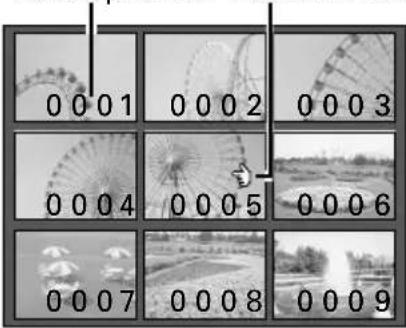
9-image Playback Screen


natural_image
Black and white photo of a large Ferris wheel and a smaller Ferris wheel against a clear sky (no text or symbols visible)4 Press the MODE button.
- If you are playing back a video clip, first press the SET button to stop the playback and then press the MODE button. (The Playback Setting Screen will not appear during the playback of a video clip.)
●The Playback Setting Screen appears. - The 9-image playback icon is selected initially.

Playback Setting Screen
5 Press the SET button.
●The 9-image Playback Screen appears.
6 Press the arrow button to move the ➕ mark to the video clip you want to view and press the SET button.
●The first frame of the selected video clip is displayed full screen. Press the SET button again to start the video clip.
- You can also move the ➕ mark by turning the control dial.
Video clip number Selection mark

9-image Playback Screen
HELP
If ? appears in the 9-image display
- ? may be displayed if the video clips were saved on the disk using a different digital disk camera.
If a video clip number is missing
- A video clip number is the actual file name for that video clip and it does not change. Therefore, if a video clip is erased (see page 149), other video clip numbers will not change to fill the open space and it may seem that a video clip number is missing. For example, if video clip number 0005 in the image above is erased, then the video clip numbers that will appear are 0001 through 0004 and 0006 through 0010.
Useful playback features for video clips
Preparation
- Insert a disk (see page 30).
●Turn the power on (see page 32).
Specific video clip number playback
Follow the procedure below to specify the video clip number of the video clip that you want to view.
1 Put the digital disk camera in the video clip playback mode.
- Set the CAMERA/PLAY switch to "PLAY."
●Turn the mode selector dial to 📄.
●The 9-image Playback Screen for video clips appears. Press the arrow button to move the 🔊 mark to the video clip you want to view and press the SET button.
2 Press the F2 button.
●The Skip File Screen appears.
- At this time, you can press the F1 button to change the folder from which to play back video clips. To change folders, after pressing the F1 button, turn the control dial to select the folder number and press the RETURN button.
3 Turn the control dial to select the video clip number of the video clip that you want to view.
●The first frame of the selected video clip is displayed full screen.
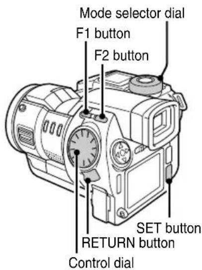
Folder number Video clip number
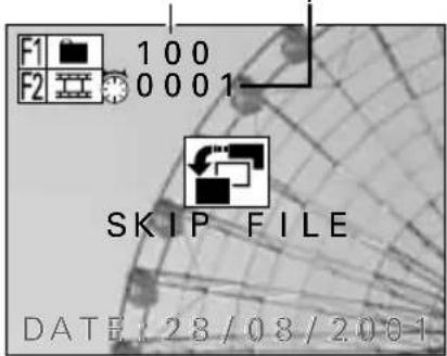
Skip File Screen
4 Press the RETURN button.
●The Skip File Screen disappears.
5 Press the SET button.
●The video clip starts.
How to play back video clips
■To pause playback
Press the SET button to pause playback.
- Press the SET button again to resume playback.
■To play back one frame at a time
① Pause playback.
② Press the arrow button.
To move forward one frame: Press ▶
To move backward one frame: Press ◀
■To return to the beginning or skip to the end
To return to the beginning of the video clip you are viewing: Press ▲ during playback.
To skip to the end of the video clip you are viewing: Press ▼ during playback.
To skip to the beginning of the next video clip: During pause, press ▼ or turn the control dial clockwise.
To return to the beginning of the previous video clip: During pause, press ▲ or turn the control dial counterclockwise.
■Viewing using the shuttle mode (viewing in 1/28ths)
① Press the RETURN button.
- You enter the shuttle mode and the Jog/Shuttle Screen appears.
- At the Jog/Shuttle Screen, press the F1 button to enter the jog mode and press the F2 button to enter the shuttle mode.
- In the shuttle mode, the video clip is divided up into 28 portions of even length and 1/28 of the video clip is skipped each time the control dial is turned one click. (This is useful to check the general contents of video clips.)
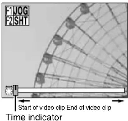
Jog/Shuttle Screen
② Slowly turn the control dial.
Advance playback: Turn the control dial clockwise.
Reverse playback: Turn the control dial counterclockwise.
- Press ▶ or ◀ to advance or reverse playback one frame at a time.
- Press ▲ or ▼ to return to the beginning or skip to the end of the video clip.
●The time indicator shows how far along the video clip playback has progressed.
③ To exit the Jog/Shuttle Screen, press the RETURN or SET button.
■Viewing using the jog mode (one frame at a time)
① Press the RETURN button.
●The Jog/Shuttle Screen appears.
② Press the F1 button.
- You enter the jog mode.
- In the jog mode, the video clip is advanced one frame at a time each time the control dial is turned one click. (This is useful to check the contents of video clips in detail.)
③ Slowly turn the control dial.
- The operation of the control dial and arrow button is the same as that for the shuttle mode above.
④ To exit the Jog/Shuttle Screen, press the RETURN or SET button.
■To adjust the volume
- Turn the mode selector dial to 📋 to display the Option Screen. Then select the audio recording icon 🎯 and press the SET button. Finally select the volume icon 🏠 and press ◀ or ▶ to adjust the volume.

Recording and playing back audio recordings
Recording audio recordings
Preparation
- Insert a disk (see page 30).
●Turn the power on (see page 32).
1 Put the digital disk camera in the option mode.
- Turn the mode selector dial to 📋 to display the Option Screen.

2 Press the arrow button to select the audio recording icon 🎯.
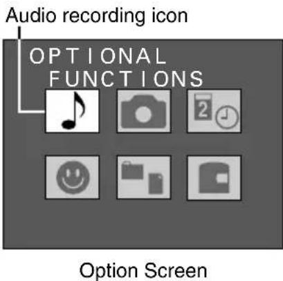
3 Press the SET button.
●The Audio Recording Screen appears.
- The record icon is selected initially.
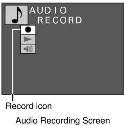
NOTE
- Besides using the built-in microphone, you can also record audio by connecting the supplied microphone to the MIC input terminal. Be aware that the built-in microphone will not work when a microphone is connected to the MIC input terminal (see page 49).
4 Press the SET button.
●The Recording Ready Screen appears.
5 Press the shutter release button.
●Audio recording starts.
- During recording, "RECORDING" appears in the monitor.
●Up to a maximum of two hours can be recorded.
6 Press the shutter release button again to stop recording.
- Recording stops and "COMPLETE" appears.
- When the Recording Ready Screen appears again, your digital disk camera is ready to begin another audio recording.
●To return to the Audio Recording Screen from the Recording Ready Screen, press the MODE button.
●To return to the Option Screen from the Audio Recording Screen, press the MODE button again.

Recording Ready Screen

Playing back audio recordings
Preparation
- Insert a disk (see page 30).
●Turn the power on (see page 32).
1 Put the digital disk camera in the option mode.
- Turn the mode selector dial to 📋 to display the Option Screen.
2 Press the arrow button to select the audio recording icon 🎯.
Audio recording icon

Option Screen
3 Press the SET button.
●The Audio Recording Screen appears.
4 Press ▼ on the arrow button to select the playback icon ▶.

Audio Recording Screen
5 Press the SET button.
●The 9-image Playback Screen for audio recordings appears.
6 Press the arrow button to move the 🔔 mark to the audio recording you want to hear and press the SET button.
●The Audio Recording Playback Setting Screen for the audio recording selected appears.
7 Press the SET button.
●Playback of the audio recording starts.

9-image Playback Screen
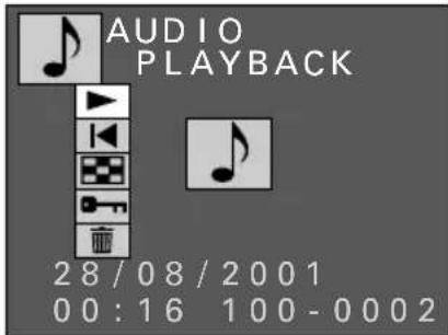
Audio Recording Playback Setting Screen
How to play back audio recordings
■To pause playback
Press the SET button to pause playback.
- Press the SET button again to resume playback.
■To change to a different audio recording
At the Audio Recording Playback Setting Screen (step 6), press ◀ or ▶.
To change to next audio recording: Press ▶
To change to previous audio recording: Press
At the Audio Recording Playback Setting Screen (step 6), select the 9-image playback icon and press the SET button.
● The 9-image Playback Screen appears. Perform steps 6 and 7 above.
■To return to the beginning
At the Audio Recording Playback Setting Screen (step 6), select the return icon ◀ and press the SET button.
●You return to the beginning of the selected audio recording.
■Adjusting the volume
- At the Audio Recording Screen (step 3 on page 69), select the volume icon ▼ and press ◀ or ▶.
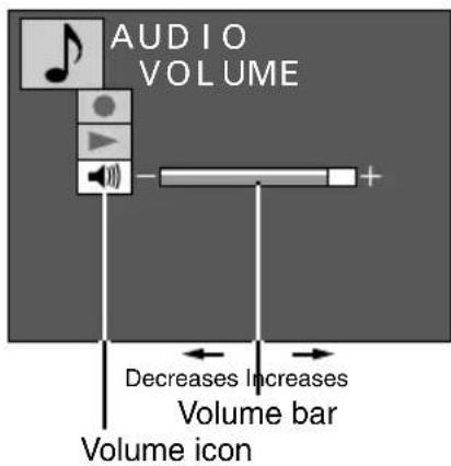
Audio Recording Screen
PLAYING BACK FILES ON A TELEVISION SET
The images, video clips, and audio recording saved on the disk in the digital disk camera can also be played back on a television set for viewing and listening. (When connected to a television set, the speaker of the digital disk camera is muted.)
Connecting the television set
Connect the supplied AV cable from the AV output terminal on the digital disk camera to the AUDIO and VIDEO input terminals on the TV.
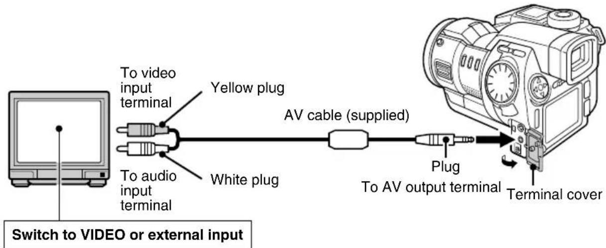
- Be careful not to connect the AV cable to the MIC input terminal.
●The audio output from the digital disk camera is monaural.
● After connecting the digital disk camera, be sure to switch the television to VIDEO or external input.
Playing the files
- To view images and video clips on the television, follow the same procedure used to play them back on the digital disk camera itself.
- To listen to audio recordings on the television, follow the same procedure used to play them back on the digital disk camera itself.
- Adjust the volume for the audio with the television controls. When the AV cable is connected, the volume control on the digital disk camera does not work.
NOTE
- The IDC-1000ZEX and IDC-1000ZE will play back images using a PAL format signal. It can only be used for playback with a PAL standard television.
- The IDC-1000ZU will play back images using an NTSC format signal. It can only be used for playback with an NTSC standard television.
- Some televisions may display a black frame around the image or cut off the edges of some of the menu screens. This is a characteristic of the television and does not indicate a malfunction.
USING THE VARIOUS SHOOTING FUNCTIONS
Using the macro focus setting
Use the macro focus setting when capturing images at close range (3 to 60 cm).
Preparation
- Set the CAMERA/PLAY switch to "CAMERA."
- Turn the mode selector dial to ☐, ☐, or ☐ to select the desired shooting mode.
1 Press the MODE button.
●The Shooting Setting Screen appears.
2 Press ▲ or ▼ on the arrow button to select the focus menu.
●The focus menu appears.


3 Press ▶ on the arrow button to select the 🎯 or 🥳 icon from the focus menu.
For macro focusing (3 to 60 cm): Select 🍴 (macro focus mode)
For macro to distant focusing (3 cm to ∞): Select 🏠 (total range focus mode)
For normal focusing (60 cm or greater): Select 🏠 (normal focus mode)
- Although you can perform macro photography with 🎨, for faster focusing, select 🎨.
4 Press the SET button.
●This completes the focus mode setting.
●The focus mode setting is retained even if the mode selector dial is turned, the CAMERA/PLAY switch is changed, or the digital disk camera is turned off (see page 112).
●The focus mode setting indicator appears in the right side of the monitor.
●To exit the Shooting Setting Screen, press the MODE button.
●Even after the Shooting Setting Screen is exited, the 🎯 or 🥼 focus setting indicator will remain.

natural_image
Black-and-white photo of sunflowers with flower petals and leaves, no visible text or symbolsFocus mode setting indicator
5 Compose the image.
- For capturing a subject from 3 to 20cm away, move the zoom switch to "T" and follow step 6 to set the focus. Especially if the subject is near 3cm away, it is important to move the zoom switch to "T" for a telescopic view.

6 Press the shutter release button.
- For how to focus the image, see step 3 on page 51.
●The image is captured with the selected macro focus setting.
NOTE
The difference between 🏠 (total range focus mode) and 🍌 (macro focus mode)
- allows you to capture images of subjects at a distance of 3 cm or greater with autofocus and without changing the focus mode setting. However, compared to 🎯 and 🥳, the time required for focusing is longer. For a faster focus, select 🎋 for objects that are close and 🥳 for object that are medium to far.
- Be aware that when you are capturing an image with both near and far objects, the ⏻ setting will not put all objects into focus.
Using the zoom
Use the zoom functions for enlarging subjects when composing images. Your digital disk camera offers two methods of zooming: optical zoom using the zoom lens and electronic zoom using the digital zoom function.
Using the optical zoom
The optical zoom allows you to enlarge up to 3x magnification.
Preparation
- Set the CAMERA/PLAY switch to "CAMERA."
- Turn the mode selector dial to ☐, ☐, or 📄 to select the desired shooting mode.
1 Set the zoom switch to "T" or "W" and compose the image.
For wide angle shooting: Set to "W"
For telescopic shooting: Set to "T"
2 Press the shutter release button.
- For how to focus the image, see step 3 on page 51.
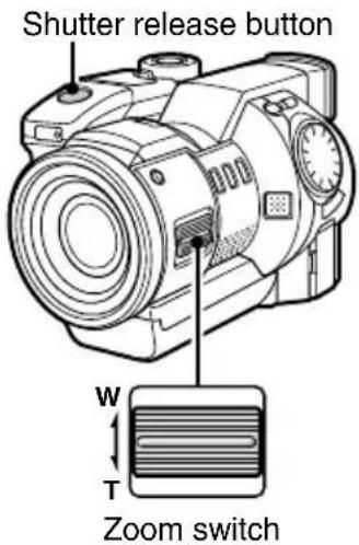
HINT
- By using the optical zoom and digital zoom together, you can enlarge the subject to even greater magnifications.
Using the digital zoom
The digital zoom allows you to enlarge the subject to be captured electronically. This is useful when you want to enlarge a subject more than that allowed by the optical zoom alone. The digital zoom can be used in the still image shooting mode when the resolution is set to 640, and in the video clip shooting mode when the resolution is 320 or 160. The digital zoom cannot be used when the resolution is 1360 or 1024 or in the sequential shot shooting mode.
Preparation
- Set the CAMERA/PLAY switch to "CAMERA."
- Turn the mode selector dial to 📄 or 🌐 to select the desired shooting mode.
1 Press the MODE button.
●The Shooting Setting Screen appears.
- The zoom icon 📁 is selected initially.
●The zoom bar also appears.
- If the zoom icon is 📁, then the zoom bar will not appear. (Depending on another setting such as the resolution, the digital zoom may not be able to be used.)
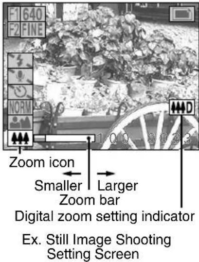
2 Press ▶ on the arrow button to enlarge the subject as desired.
● Each time ▶ is pressed, the pointer on the zoom bar moves to the right and the subject is enlarged.
- To return the subject to the original size, press ◀. The pointer moves back to the left.
● The magnification provided by the digital zoom depends on the resolution as shown below. Magnification
Resolution 640: 1 to 2.1x (5 levels) ......For still images
Resolution 320: 1 to 2x (5 levels) ......For video clips
Resolution 160: 1 to 4x (5 levels) ......For video clips
- When the digital zoom is set, the digital zoom setting indicator 📂 appears.
●The digital zoom setting is retained even if the mode selector dial is turned, the CAMERA/PLAY switch is changed, or the digital disk camera is turned off (see page 112).
3 Press the shutter release button.
- For how to focus, see step 3 on page 51.
●The image is captured zoomed up as set.
●To exit the Shooting Setting Screen, press the MODE button.
Using the flash
The flash is not only used to capture images in the dark, but also to capture images of subject that are in shadows or lit from behind. Your digital disk camera has four flash modes: automatic flash mode, red-eye reduction flash mode, forced flash mode, and flash off mode. Select the mode depending on the situation and conditions.
The flash range is given below.
Normal focus: 60 cm to 2.8 m (optical zoom set to "W")
60 cm to 1.5 m (optical zoom set to "T")
Macro focus: 20 cm to 60 cm
Preparation
- Set the CAMERA/PLAY switch to "CAMERA."
- Turn the mode selector dial to 📄 to select the still image shooting mode.
1 Press the flash pop-up button.
●The flash stands up at the front of the digital disk camera.
●The flash will not operate unless it has been stood up with the flash pop-up button.

Flash pop-up button
2 Press the MODE button.
●The Still Image Shooting Setting Screen appears.
3 Press ▲ or ▼ on the arrow button to select the flash menu.
- If the flash has not been stood up, the flash off mode will be set.
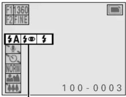
Flash menu
Still Image Shooting Setting Screen
4 Press ▶ on the arrow button to select the desired flash mode icon from the flash menu.
A (automatic flash): The digital disk camera will detect the subject brightness and use the flash when required.
(4) (red-eye reduction flash): This flash mode reduces the amount that people's eye turn red when subjected to a camera flash. When the shutter release button is pressed, the flash will first emit preparatory flashes and then the actual flash when the image is captured. The preparatory flashes reduce the amount of redness in the subject's eyes. The red-eye reduction flash mode will detect the brightness of the subject and only flash when necessary.
(forced flash): The flash will operate with every image captured regardless of the conditions. Use this setting under backlight conditions, when the subject is in the shade, under fluorescent lighting conditions, etc.
5 Press the SET button.
●This completes the flash mode setting.
- Place the flash back in the digital disk camera to set the flash off mode ⚡️.
●The flash mode setting is retained even if the flash is placed back in the digital disk camera, the mode selector dial is turned, the CAMERA/PLAY switch is changed, or the digital disk camera is turned off (see page 112).
- By setting the desired flash mode beforehand, you can turn the flash on and off by just standing up the flash and putting it back.
- To exit the Shooting Setting Screen, press the MODE button.

6 Press the shutter release button.
●The image is captured with the selected flash mode setting.
NOTE
- With sequential shots (see page 56), video clips (see page 61), audio recordings (see page 68), and interval shooting (see page 98), the flash cannot be used.
HELP
If capturing cannot be done after the flash is used
- Capturing cannot be performed while the flash is being recharged. The clock icon 📁 appears while the flash is being recharged. Wait until the clock icon disappears before composing the next image.
Recording a voice memo
In the still image shooting mode, you can record up to 10 seconds of audio when capturing an image. This sound file is called a voice memo. You can also add a voice memo to an image captured earlier (see “Adding a voice memo” on page 127).
Preparation
- Set the CAMERA/PLAY switch to "CAMERA."
- Turn the mode selector dial to 📄 to select the still image shooting mode.
1 Press the MODE button.
●The Still Image Shooting Setting Screen appears.

Still Image Shooting Setting Screen
2 Press ▲ or ▼ on the arrow button to select the voice memo menu.
●The voice memo menu appears.
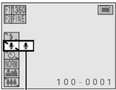
Voice memo menu
3 Press ▶ on the arrow button to select the voice memo icon 🖼️.
To record a voice memo: Select ⚙ (voice memo on)
To not record a voice memo: Select 🖼 (voice memo off)
4 Press the SET button.
●This completes the voice memo setting.
●The voice memo setting indicator appears in the right side of the monitor.
●The voice memo setting returns to voice memo off if the mode selector dial is turned, the CAMERA/PLAY switch is changed, or the digital disk camera is turned off.
●To exit the Still Image Shooting Setting Screen, press the MODE button.
●Even after the Still Image Shooting Setting Screen is exited, the voice memo setting indicator ⚙ will remain.
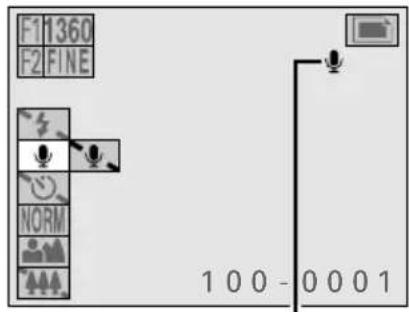
Voice memo setting indicator
5 Press the shutter release button.
●The image is captured and then the voice memo is recorded.
- While the voice memo is being recording, the REC icon will appear in the monitor.
●Up to a maximum of 10 seconds can be recorded.
●To stop the recording before the 10 seconds elapses, press the shutter release button again.
- If the shutter release button is not pressed, then the maximum 10 seconds will be recorded.
●Even after the recording is finished, the voice memo on settings remains unchanged.
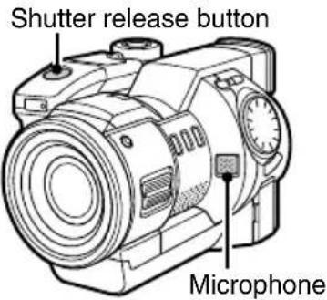
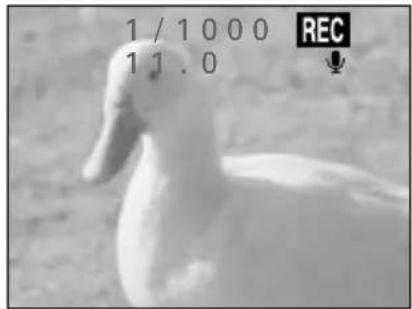
NOTE
- The voice memo sound file takes up approximately one-half the disk space required by one image with resolution 640 and compression ratio NORM.
- Besides using the built-in microphone, you can also record the voice memo by connecting the supplied microphone to the MIC input terminal. Be aware that the built-in microphone will not work when a microphone is connected to the MIC input terminal (see page 49).
Using the self-timer
The self-timer function allows you to have the digital disk camera wait 10 seconds after the shutter release button is pressed until it captures the image or starts recording. You can also change the amount of time the digital disk camera will wait from anywhere between 0 seconds to 9 hours 59 minutes 59 seconds.
* When using the self-timer, be sure to use a tripod or other means of holding the digital disk camera.
Preparation
- Set the CAMERA/PLAY switch to "CAMERA."
- Turn the mode selector dial to ☐, ☐, or ☐ to select the desired shooting mode.
1 Press the MODE button.
●The Shooting Setting Screen appears.
2 Press ▲ or ▼ on the arrow button to select the self-timer menu.
●The self-timer menu appears.
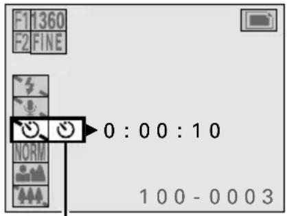
Timer menu
Shooting Setting Screen
3 Press ▶ on the arrow button to select the self-timer icon ☺.
- To set the self-timer: Select 🤨 (self-timer on)
- To not set the self-timer: Select 🤘 (self-timer off)
4 Press the SET button.
●This completes the self-timer setting.
- The timer mark ⏻ and the time until images are captured or recording is started appear in the mode display panel.
- The default time for the self-timer is 10 seconds. If you will not change this setting, skip to step 6.
- If you want to change the time for the self-timer, proceed to step 5.
- The self-timer setting returns to self-timer off and the self-timer time returns to 10 seconds if the mode selector dial is turned, or the digital disk camera is turned off.
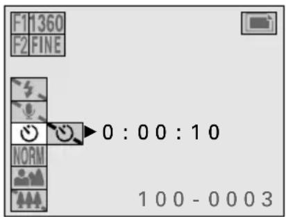
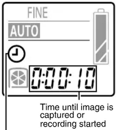
Timer mark
Mode display panel
5
Press ◀ or ▶ on the arrow button to highlight in orange the numbers to change.
- This is the time for the self-timer, or the time the digital disk camera waits until capturing images or starting recording after the shutter release button is pressed (hrs:min:sec).
- Using the arrow button, set the desired time for the self-timer.
How to set the time
Decrease the value: Press ▲
Increase the value: Press ▼
Move to the right: Press ▶
Move to the left: Press
- To exit the Shooting Setting Screen, press the MODE button.
6
Press the shutter release button.
- The self-timer lamp lights and then starts flashing three seconds before images are captured or recording starts.
- If the time for the self-timer is set to one minute or greater, the monitor automatically turns off. (If in this condition the EJECT lever is pushed, the digital disk camera turns off and the self-timer is stopped.) To turn the monitor on, press the power button; to turn it back off, press the power button again.
- You can check the time remaining before images are captured or recording starts at the mode display panel (see page 80).
- To stop the self-timer, press the MODE button when the monitor is turned on. To start the self-timer again, press the shutter release button.
- If the LCD monitor was turned off, the digital disk camera automatically turns off after the image is captured or the recording finished.

Time until image is captured or recording started (hrs:min:sec)
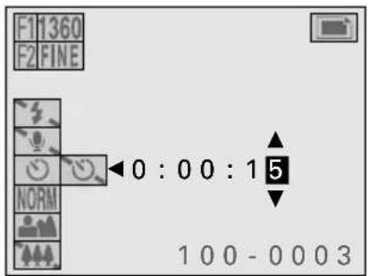

NOTE
Turning off the digital disk camera during the self-timer
- The power does not turn off if the power button is pressed during the self-timer. To turn off the digital disk camera, press the MODE button while the LCD monitor is turned on to stop the self-timer, and then press the power button.
Capturing a AE-shifted sequential shot
The AE shift sequential shot captures seven sequential images while automatically changing the exposure from under exposure (for a dark image) to over exposure (for a light image).
Dark image (under exposed) (Standard exposure) Bright image (over exposed)

flowchart
graph LR
    A["Plant"] --> B["Large plant"]
    B --> C["Small plant"]
    C --> D["Medium plant"]
    D --> E["Small plant"]
    E --> F["Large plant"]
    F --> G["Small plant"]
Preparation
- Set the CAMERA/PLAY switch to "CAMERA."
- Turn the mode selector dial to ☐ to select the sequential shot shooting mode.
1 Press the MODE button.
● The Sequential Shot Shooting Setting Screen appears.
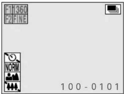
Sequential Shot Shooting Setting Screen
2 Press ▲ or ▼ on the arrow button to select the sequential shot menu.
● The sequential shot menu appears.

Sequential shot menu
3 Press ▶ on the arrow button to select the AE shift icon 🧑️.
AE shift sequential shot: Select
Normal sequential shot: Select NORM
- If the exposure control setting (see page 92) is set to a setting other than program AE, then the AE shift icon cannot be selected. For the AE shift sequential shot, change the exposure control setting to program AE (see page 94).
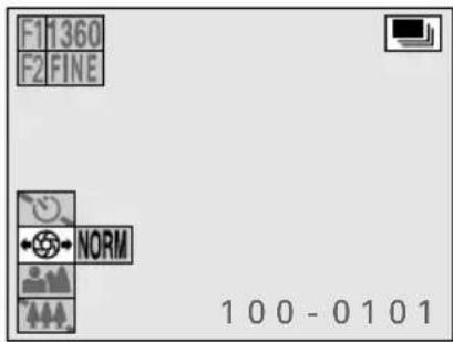
4 Press the SET button.
● This completes the AE shift sequential shot setting.
- The AE shift sequential shot setting returns to the normal sequential shot if the mode selector dial is turned, the CAMERA/PLAY switch is changed, or the digital disk camera is turned off.
- To exit the Shooting Setting Screen, press the MODE button.
5 Press the shutter release button.
● The AE shift sequential shot is taken.
- While the AE shift sequential shot images are being captured, the REC icon will appear in the monitor.
- Even after the AE shift sequential shot is finished, the AE shift sequential shot setting remains unchanged.
Recording mark
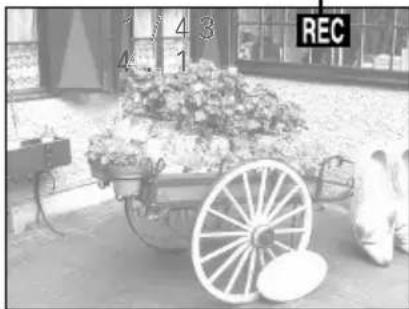
natural_image
Black-and-white photo of a vintage wooden wagon with flowers and a person sitting beside it, no visible text or symbols.NOTE
- For the AE shift sequential shot, even if you have set the exposure correction (see page 87), the exposure correction value is returned to ± 0 and then the AE shift sequential shot is captured.
- For the sequential shot shooting mode, the TIFF compression ratio cannot be set.
About the sequential shot speed
- The sequential shot speed for sequential shots depends on the resolution.
Resolution 1360: 7.5 images/second (approx. 0.13 seconds/image)
Resolution 1024: 7.5 images/second (approx. 0.13 seconds/image)
Resolution 640: 30 images/second (approx. 0.03 seconds/image)
HELP
If the exposure does not change
- If the subject is too bright or too dark, the exposure may not change as required.
Setting the image quality
The resolution and compression ratio settings determine the image quality. Set these settings according to the image quality you desire.
Setting the resolution
Use the procedure given below to set the image resolution. If the resolution is increased (larger number of pixels per image), the image quality will improve, but the remaining number of images that can be taken will decrease. In the video clip shooting mode, if the resolution is decreased, the length of time possible for the video clip will increase, but the size of the playback image will decrease. It is therefore important to select the resolution according to the desired image quality and purpose.
| Resolution (units: pixels)[Icon displayed on the LCD monitor] | ||||||
| 1360 x 10241360 | 1024 x 7681024 | 640 x 480640 | 320 x 240320 | 160 x 120160 | ||
| Shooting mode | Still image Yes | Yes Yes No | No | |||
| Sequential shot | Yes Yes Yes | No No | ||||
| Video clip No | No Yes Yes | Yes | ||||
Preparation
- Set the CAMERA/PLAY switch to "CAMERA."
- Turn the mode selector dial to ☐, ☐, or ☒ to select the desired shooting mode.
1 Press the F1 button.
● The current resolution appears in the upper left-hand corner of the monitor for two seconds.
- The current resolution also appears in the mode display panel for two seconds.
- The resolution setting changes each time the F1 button is pressed.
1360: For 1360 x 1024 resolution
1024: For 1024 x 768 resolution
640: For 640 x 480 resolution
320: For 320 x 240 resolution
160: For 160 x 120 resolution
- Some resolution cannot be set for some shooting modes (see table above).
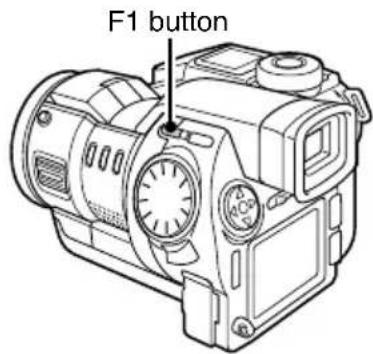

Resolution Ex. Still Image Shooting Screen
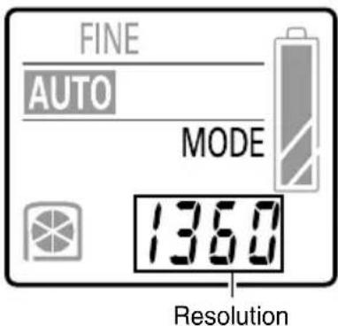
Mode display panel
Setting the compression ratio
Use the procedure given below to set the compression ratio. Even if the same resolution is used, you can change the compression ratio setting and increase the compression amount to capture more images by decreasing the image data size, or decrease the compression amount for no loss in image quality.
* The compression ratio cannot be set for video clips.
Preparation
- Set the CAMERA/PLAY switch to "CAMERA."
- Turn the mode selector dial to ☐ or ☐ to select the still image or sequential shot shooting mode.
1 Press the F2 button.
● The current compression ratio appears in the upper left-hand corner of the monitor for two seconds.
- The compression ratio setting changes each time the F2 button is pressed as shown below.

TIFF: Stores the data in TIFF format (no compression for highest quality)
FINE: Stores the data with low compression (high quality)
NORM: Stores the data with moderate compression (normal quality)
- You cannot set the compression ratio TIFF in the sequential shot shooting mode.
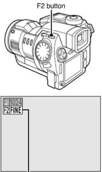
Compression ratio
NOTE
About the resolution and compression settings
- The image captured by a digital disk camera consists of a collection of small dots. The resolution refers to the number of these dots, and the greater the number, the higher the image quality. As the resolution increases, the size of the resulting data also increases, and the number of images that can be captured decreases. To compensate for this, this digital disk camera is able to compress the data. This digital disk camera uses JPEG compression.
- If JPEG compression is used, when the image is returned to its original size, an extremely small portion of it is lost. The higher the compression ratio, the more of the original image is lost. Therefore, this digital disk camera also allows you to store image data without any compression to ensure that none of the original image is lost. This is the TIFF compression ratio. It is important to select the resolution and compression setting that you require for your applications.
About TIFF format
- The TIFF format used by your digital disk camera conforms to TIFF Rev. 6.0 "Extension YCbCr Images v" used by the Exif standards for non-compressed YCbCr data. If you are downloading images to a personal computer, you will need a YCbCr TIFF-compatible application to view them. The applications included in the SANYO Software Pack are YCbCr TIFF-compatible.
Setting the frame rate
Follow the procedure below to set the frame rate at which video clips are recorded. The frame rate tells you how many frames are recorded each second. The greater the frame rate, the smoother the motion in the video clip, but also the larger the size of the video clip file.
Caution
- Although video clips recorded at different frame rates can be joined using the video clip editing functions (see page 139), the video clip recorded at 30 frames/second will be converted to 15 frames/second. If you are going to join video clips together, it is recommended to record them at the same frame rate.
Preparation
- Set the CAMERA/PLAY switch to "CAMERA."
- Turn the mode selector dial to 📄 to select the video clip shooting mode.
1
Press the F2 button.
● The current frame rate appears in the upper left-hand corner of the monitor for two seconds.
● The current frame rate also appears in the mode display panel for two seconds.
- The frame rate setting changes each time the F2 button is pressed.
15f: Records video clips at 15 frames/second
30f: Records video clips at 30 frames/second
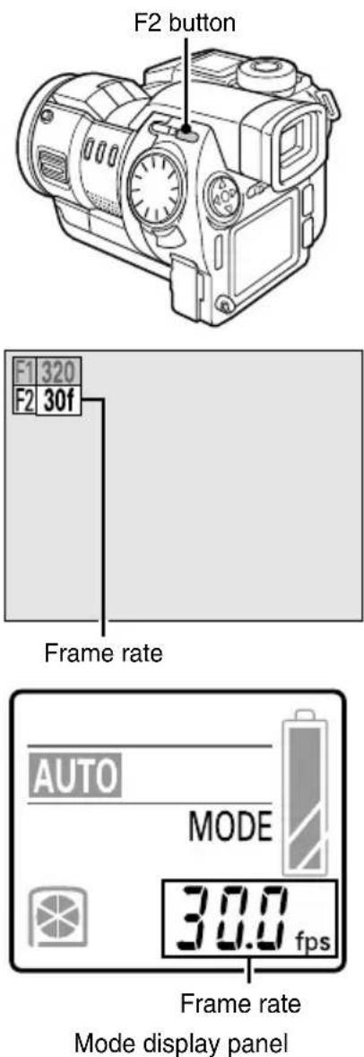
Setting the exposure correction
Preparation
- Set the CAMERA/PLAY switch to "CAMERA."
- Turn the mode selector dial to ☐, ☐, or 📄 to select the desired shooting mode.
1 Turn the control dial.
● The Exposure Correction Screen appears.
- If the exposure control setting (see page 92) is set to a setting other than program AE, then the Exposure Correction Screen will not appear. To set the exposure correction, change the exposure control setting to program AE (see page 94).
- If the AE shift sequential shot is selected (see page 82), the Exposure Correction Screen will not appear. To set the exposure correction, change back to the normal sequential shot mode (see page 83).
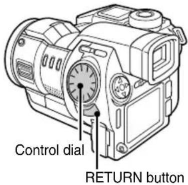
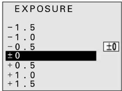
Exposure Correction Screen
2 Turn the control dial to select the desired exposure correction value.
- The exposure correction can be set from to -1.5 EV to +1.5 EV in 0.5-EV increments.
- Select positive values for brighter images and negative values for darker images.
- Set ± 0 EV for automatic exposure correction.
3 Wait two seconds.
● The exposure correction is entered and the Exposure Correction Screen disappears.
● The exposure correction value appears in the right side of the monitor.
- You can also enter the exposure correction setting and exit the Exposure Correction Screen by pressing the RETURN button.

Exposure correction value
NOTE
● To clear the exposure correction setting, select ±0 at step 2.
MANUAL MODE SETTINGS
About the manual mode settings
Your digital disk camera is equipped with a manual mode and automatic mode. The manual mode settings (see pages 90 to 97) are stored even after the digital disk camera is turned off so it is unnecessary for you to set the manual mode settings each time you switch to the manual mode. This allows you to use the automatic mode and switch to your previously set manual mode settings only when necessary. (You can also set your digital disk camera so that the manual mode settings are cleared each time it is turned off. See page 112.)
By becoming familiar with the manual mode settings, you can perform many different types of interesting effects for a wider range of interesting applications. The settings for the manual and automatic modes are made separately for the still image, sequential shot, and video clip shooting modes.
Automatic mode settings
In the automatic mode, the digital disk camera performs the following settings automatically.
- Focus setting
The focus is set automatically within the distance range of the focus mode set at the focus menu.
- Exposure control setting
The exposure (shutter speed and aperture) is set automatically according to the subject conditions. (Program AE)
- White balance setting
The white balance is set automatically according to the subject conditions. (Auto white balance)
Manual mode settings
In the manual mode, you can set the following settings as desired for the scene you are shooting.
- Focus setting
You can set auto focus, manual focus, and fixed focus.
- Exposure control setting
You can set program AE, AE lock, spot sample AE, shutter speed priority AE, aperture priority AE, and manual exposure (allows setting the shutter speed and aperture as desired).
- White balance setting
You can set auto white balance, white balance lock, sampling white balance, sunny sky, cloudy sky, fluorescent lighting, and tungsten lighting.
Switching between the automatic and manual modes
Follow the procedure below to change between the automatic and manual modes.
Preparation
- Set the CAMERA/PLAY switch to "CAMERA."
- Turn the mode selector dial to ☐, ☐, or 📋 to select the desired shooting mode.
1 Perform the manual mode settings (see pages 90 to 97).
2 Press the AUTO/MAN button.
- The digital disk camera changes between the automatic and manual modes each time the AUTO/MAN button is pressed.
- In the manual mode, the various settings are displayed, and in the automatic mode, they disappear.
- AUTO appears in the mode display panel in the automatic mode, and MANUAL appears in the manual mode.
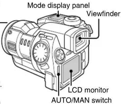
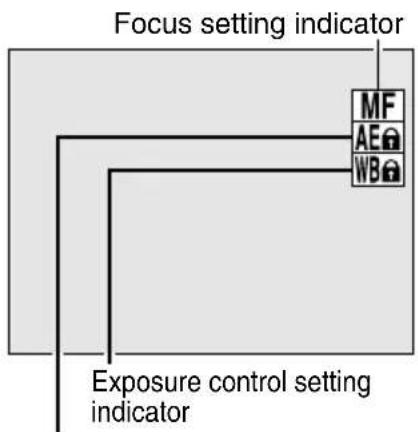
flowchart
graph TD
    A["Focus setting indicator"] --> B["MF"]
    A --> C["AE"]
    A --> D["WB"]
    E["Exposure control setting indicator"] --> B
    E --> C
    E --> D
White balance setting indicator Example of Manual Shooting Screen LCD monitor (or viewfinder)

For manual shooting Mode display panel
Setting the focus
In addition to autofocus, your digital disk camera also allows you to set the focus manually or fix the focus to a preset distance.
Setting to manual focus
Preparation
- Set the CAMERA/PLAY switch to "CAMERA."
- Turn the mode selector dial to 📄, 📋, or 🌐 to select the desired shooting mode.
1 Press the FOCUS button.
● The Manual Focus Screen appears.
- If the Fixed Focus Screen (see page 91) appears, turn the control dial to select "MAN. FOCUS" and press the RETURN button.
2 Turn the focus ring to set the focus you desire.
- Turn the focus ring fast to change the focus distance drastically, and turn the focus ring slowly to change the focus distance gradually.
● To aid in setting the focus, the focus distance and a focus bar appear in the monitor. - The focus bar is given as a guide. When the focus bar is extended all the way to the top, the focus is set appropriately for the measured distance.
- When the manual focus is set, the manual focus indicator MF appears.
3 Press the RETURN button.
● This completes the manual focus setting.
- When the manual focus is set, the focus distance indicator appears.
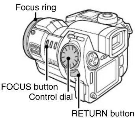
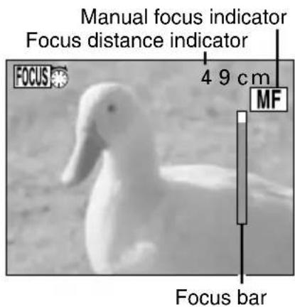
Manual Focus Screen
■ To return to autofocus, select "AUTO FOCUS" at the Fixed Focus Screen and press the RETURN button. (The manual focus indicator will disappear.)
NOTE
● The focus distance is the measured distance from the lens to the subject.
- Depending on the subject, there are rare occasions when the focus bar may not extend all the way to the top. In such a case, check the focus using the image in the monitor.
Setting to fixed focus
Preparation
- Set the CAMERA/PLAY switch to "CAMERA."
- Turn the mode selector dial to ☐, ☐, or ☐ to select the desired shooting mode.
The setting allows you to fix the focus setting. This is useful when you know the distance of the subject beforehand.
1 Set the focus mode (see page 72).
- The distances that can be set for fixed focus will differ depending on the focus mode set.
2 Press the FOCUS button.
● The Manual Focus Screen appears (see page 90).
- If the Fixed Focus Screen appears at this step, skip to step 4.
3 Turn the control dial.
● The Fixed Focus Screen appears.
- The contents of the Fixed Focus Screen will differ depending on which focus mode is set: macro focus mode, total range focus mode, or normal focus mode (see page 72).
4 Turn the control dial to select the desired focus distance.
5 Press the RETURN button.
● This completes the fixed focus setting.
- When the fixed focus is set, the focus distance indicator appears.
■ To return to autofocus, select "AUTO FOCUS" at the Fixed Focus Screen and press the RETURN button. (The focus distance indicator will disappear.)

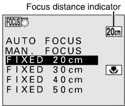
Fixed Focus Screen for macro focusing
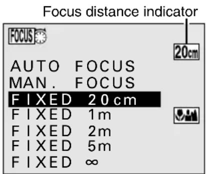
Fixed Focus Screen for total range focusing
NOTE
- If you change the focus mode (see page 72) after setting the manual focus (see page 90) or the fixed focus, the digital disk camera will return to autofocus.
Setting the exposure control
Your digital disk camera allows you to set a number of different exposure controls (shutter speeds and aperture settings). By becoming familiar with these settings, you can create a wide variety of expressions in your images.
Preparation
- Set the CAMERA/PLAY switch to "CAMERA."
- Turn the mode selector dial to ☐, ☐, or 📄 to select the desired shooting mode.
1 Press the EXP button.
- The EXP indicator appears. If you are going to set a setting other than AE lock, proceed to step 2.
- If the EXP button is pressed while program AE is set (the initial setting), the AE lock function activates and the exposure is locked to the setting when the EXP button was pressed. After the exposure is locked, the AE indicator appears.
- To perform shooting with this locked exposure setting, press the RETURN button. By pressing the AUTO/MAN button, you can now switch back and forth between program AE and this locked setting.
- If the EXP button is pressed while spot sample AE, shutter speed priority AE, aperture priority AE, or manual exposure is set, the Exposure Control Setting Screen in step 2 appears.
2 Turn the control dial to select the desired exposure control setting.
● The Exposure Control Setting Screen appears.
PROGRAM: Program AE
- For having the digital disk camera automatically set a proper shutter speed and aperture according to the subject brightness.
● This is the setting for automatic mode.
Example: For simple shooting that requires minimum setup.
AE LOCK: AE Lock
- As when the EXP button is pressed in step 1 above, when you select AE LOCK and press the RETURN button, the exposure is locked to the current setting. This exposure is locked and will be used when the shutter release button is pressed.
Example: For setting the exposure beforehand and then shooting.
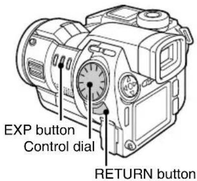
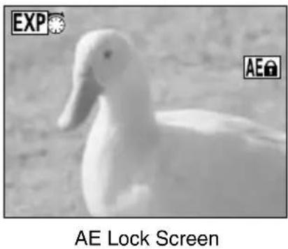
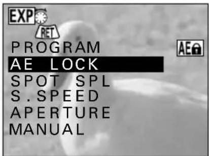
Exposure Control Setting Screen
SPOT SPL: Spot sample AE
- The exposure is set based on the light measured at the middle of the monitor. Shooting is performed with the exposure set to a portion of the subject.
Example: For setting the exposure to a person's face while there is a sunset in the background.
S.SPEED: Shutter speed priority AE
- This allows you to set a specific shutter speed and have the digital disk camera automatically set an appropriate aperture.
Example: For setting a fast shutter speed to capture a fast-moving object. Or for setting a slow shutter speed to shoot the flow of a slow-moving object or background scene.
APERTURE: Aperture priority AE
- This allows you to set a specific aperture and have the digital disk camera automatically set an appropriate shutter speed.
Example: For opening the aperture for portraits with a blurred background (for a shallow the field depth). Or for closing the aperture for a clear foreground and background (for a deep field depth).
MANUAL: Manual exposure
● This allows you to set a specific shutter speed and aperture as desired.
Example: For setting a slow shutter speed when shooting in a dark location without using a flash. Or for shooting nighttime scenes where lights flows across the image.
3 Press the RETURN button.
- When "PROGRAM" is not selected, set the exposure following the procedures given below after pressing the RETURN button.
■ When selecting "AE LOCK" and pressing the RETURN button
- The exposure is set to the value when the RETURN button is pressed.
- While AE lock is set, the indicator AE ^① appears.
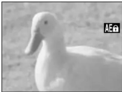
natural_image
Black and white photo of a duck-like animal (no text or symbols visible)AE Lock Screen
■ When selecting "SPOT SPL" and pressing the RETURN button
- A frame for the measurement area appears in the center of the monitor.
- Aim the measurement area at the spot to which you want to set the exposure and press the RETURN button again. The light is measured and the AE value is set (spot sample AE).
- While spot sample AE is set, the indicator SPOT appears.

Measurement area
Spot Sample AE Setting Screen
■ When selecting "S.SPEED" and pressing the RETURN button
- Sets the AE with shutter speed priority.
● The Shutter Speed Setting Screen appears. - Turn the control dial to select the desired shutter speed and press the RETURN button.
● The shutter speeds that can be selected will differ depending on the current shooting mode.
Still Image Shooting Mode:
1/500 to 16 seconds
Sequential Shot Shooting Mode:
1/2000 to 1/30 seconds (resolution 640)
1/2000 to 1/15 seconds (resolution 1360 or 1024)
Video Clip Shooting Mode:
1/2000 to 1/30 seconds (frame rate 30f)
1/2000 to 1/15 seconds (frame rate 15f)
- When the shutter speed priority AE is set, the indicator S appears.
Shutter speed setting

natural_image
Black-and-white photo of a duck with no visible text or symbolsShutter Speed Setting Screen
■ When selecting "APERTURE" and pressing the RETURN button
- Sets the AE with aperture priority.
● The Aperture Setting Screen appears. - Turn the control dial to select the desired aperture and press the RETURN button.
- When the ND filter is activated to reduce the passage of light, “+ND” appears to the right of the aperture setting.
- When the aperture priority AE is set, the indicator A appears.
Aperture setting
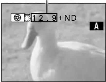
Aperture Setting Screen
■ When selecting "MANUAL" and pressing the RETURN button
● The Manual Exposure Setting Screen appears.
- To set the shutter speed, press the F1 button and turn the control dial.
- To set the aperture, press the F2 button and turn the control dial.
● After setting the desired shutter speed and aperture, press the RETURN button.
- When manual AE is set, the indicator M appears.
Shutter speed setting Aperture setting
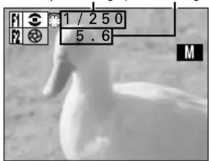
Manual Exposure Setting Screen
■ To return to program AE, press the EXP button to display the Exposure Control Setting Screen, select "PROGRAM," and press the RETURN button.
HINT
To capture images of people with night scenery in the background
- By using the flash and a slow shutter speed together, the foreground subject and background night scenery will both be captured well. With a slow shutter speed, the flash lights when the shutter opens so the foreground people are captured and the shutter stays open for a long exposure so the dark background is also captured.
NOTE
- When setting a slow shutter speed, it is recommended to use a tripod or other means to prevent the digital disk camera from moving.
- When setting a slow shutter speed, there are rare occasions when small points of light are also captured. This is a characteristic of the imaging element and not a malfunction.
Setting the white balance
Preparation
- Set the CAMERA/PLAY switch to "CAMERA."
- Turn the mode selector dial to ☐, ☐, or 📄 to select the desired shooting mode.
- The indicator W.BAL appears. If you are going to set a setting other than white balance lock, proceed to step 2.
- If the W.BAL button is pressed while auto white balance is set (the initial setting), the white balance lock function activates and the white balance is locked to the setting when the W.BAL button was pressed. After the white balance is locked, the indicator appears.
- To perform shooting with this locked white balance setting, press the RETURN button. By pressing the AUTO/MAN button, you can now switch back and forth between auto white balance and this locked setting.
- If the W.BAL button is pressed while sampling white balance, fine sky white balance, cloudy sky white balance, fluorescent white balance, or tungsten white balance is set, the White Balance Setting Screen in step 2 appears.

RETURN button
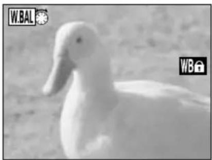
natural_image
Black-and-white photo of a duck with visible beak and bird, no text or symbols presentWhite Balance Lock Screen
2 Turn the control dial.
● The White Balance Setting Screen appears.
AUTOMATIC: Auto white balance
- For having the digital disk camera automatically set a proper white balance according to the light source. The setting for the automatic mode.
WB LOCK: White balance lock
- As when the W.BAL button is pressed in step 1 above, when you select WB LOCK and press the RETURN button, the white balance is locked to the current setting.
- When white balance lock is set, the indicator WB appears.

White Balance Setting Screen
SAMPLING WB: Sampling white balance
- For setting the white balance more accurately. Used for when the light source cannot be specified.
- When sampling white balance is set, the indicator 📋 appears.
FINE SKY: Fine sky white balance
- Sets the white balance to a value proper for when the light source is a sunny day.
- When fine sky white balance is set, the indicator 🙏 appears.
CLOUDY SKY: Cloudy sky white balance
- Sets the white balance to a value proper for when the light source is a cloudy day.
- When the cloudy sky white balance is set, the indicator 📁 appears.
FLUORESCENT: Fluorescent white balance
- Sets the white balance to a value proper for when the light source is fluorescent lighting.
- When the fluorescent white balance is set, the indicator 📄 appears.
- Sets the white balance to a value proper for when the light source is tungsten lighting.
- When the tungsten white balance is set, the indicator 🙏 appears.
3
Turn the control dial to select the desired white balance setting and press the RETURN button.
- This completes the white balance setting. The white balance setting indicator appears in the right side of the monitor.
- If you selected "SAMPLING WB," after you press the RETURN button, perform the operations below to complete the white balance setting.
① Aim the camera at a plain sheet of white paper and fill the entire monitor with the paper.
② Press the RETURN button again.
- This completes the sampling white balance setting.
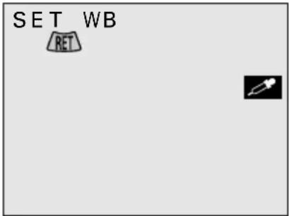
■ To return to auto white balance, press the W.BAL button to display the White Balance Setting Screen, select "AUTOMATIC," and press the RETURN button.
HINT
To capture sepia-tone images
- At ① of step 3, instead of using a white sheet of paper to set the white balance, use a blue one. You can experiment by changing the paper color with which the white balance is set for different results.
INTERVAL SHOOTING
Interval shooting is a special shooting feature where the digital disk camera captures images in set intervals. There are two types of interval shooting: still image interval shooting captures still images in set intervals and video clip interval shooting captures images in set intervals that will then become one video clip (see page 101).
With interval shooting, you can effectively capture the blooming of a flower blooming or other such extremely slow movement.
Still image interval shooting
Example: Capturing five images in ten-minute intervals.

flowchart
graph LR
    A["1 image captured"] --> B["10-minute interval"]
    B --> C["1 image captured"]
    C --> D["10-minute interval"]
    D --> E["1 image captured"]
    E --> F["10-minute interval"]
    F --> G["1 image captured"]
Preparation
- Set the CAMERA/PLAY switch to "CAMERA."
- Turn the mode selector dial to 📄 to select the still image shooting mode.
1 Press the MODE button.
● The Still Image Shooting Setting Screen appears.
- The resolution and compression ratio settings cannot be changed in the middle of interval shooting. If necessary, change these settings as desired before proceeding to step 2.
2 Press ▲ or ▼ on the arrow button to select the special shooting menu.
● The special shooting menu appears.

Special shooting menu Still Image Shooting Setting Screen
3 Press ▶ on the arrow button to select the INT icon.
For interval shooting: Select INT
For normal shooting: Select NORM
NOTE
- By fixing the settings for still image interval shooting, the images of the slow changes in the subject over time are captured more accurately. If interval shooting is performed with the digital disk camera set to autofocus, program AE, and auto white balance, then each image may be captured with slightly different settings making each image slightly different. To avoid this, set AE lock (see page 92) and white balance lock (see page 96) and set the focus manually.
- With still image interval shooting, you can use the voice memo (see page 78) and self-timer (see page 80) functions; you cannot use the flash (see page 76).
4 Press the SET button.
● The Still Image Interval Shooting Setting Screen appears.
5 Set the interval shooting parameters.
- Set the interval between images at "INT" and the number of images to be captured at "FRAME."
■ Performing the settings at the Still Image Interval Shooting Setting Screen
To change a setting: Press ▲ or ▼
To move to the next item: Press ▶
To move to the previous item: Press ◀
To cancel the settings and return to the Shooting Setting Screen: Press the MODE button
- The smallest interval that can be set will differ depending on the compression ratio and voice memo settings.
| Compression ratio | Smallest interval | |
| No voice memo | With voice memo | |
| TIFF | 30 seconds 45 | seconds |
| FINE 10 | seconds 30 seconds | |
| NORM 10 | seconds 30 seconds | |
- The largest interval that can be set is 9 hours 59 minutes 59 seconds.
- Between 1 and 999 images can be captured, depending on the remaining disk space and the amount of images in the folder to which you are saving (see page 148).
6 Press the SET button.
● The Still Image Interval Shooting Ready Screen appears.
- To stop the interval shooting before it is completed, press the MODE button.
- The timer mark and the time until the next image is captured (hrs:min:sec) appear in the mode display panel.
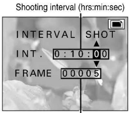
Number of frames
Still Image Interval Shooting Setting Screen
Ex. When capturing 5 images in 10-minute intervals
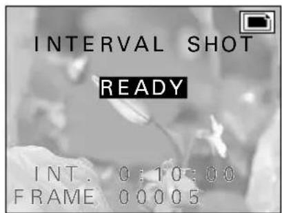
Still Image Interval Shooting Ready Screen
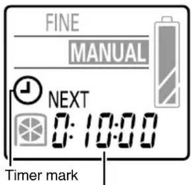
Time until next image is captured (hrs:min:sec)
Mode display panel
NOTE
- In order to perform interval shooting with 999 images, the folder to which the images are being saved must be empty of still images. You can also create a new folder (see page 115) and select that folder for saving the images.
7 Press the shutter release button.
- The still image interval shooting begins and the first image is captured.
● The monitor turns off. To turn the monitor back on, press the power button. To turn it back off, press the power button again. - When the time set in step 5 elapses, the next image is captured.
- When the set number of images is captured, the interval shooting is completed. To pause or end the interval shooting beforehand, perform the operations given below.
■ Pausing or ending still image interval shooting
① Press the power button to turn on the monitor and press the MODE button.
● The Still Image Interval Shooting Completion Screen appears. When this screen appears, the timer stops and the interval shooting is paused.
② Press ▲ or ▼ to select "STOP" or "CONTINUE."
CONTINUE: Resumes the interval shooting STOP: Ends the interval shooting
③ Press the SET button.
- If you selected "CONTINUE," the interval shooting resumes.
- If you selected "STOP," the interval shooting is ended and you return to the Still Image Shooting Setting Screen (step 1).
Shooting interval (hrs:min:sec)
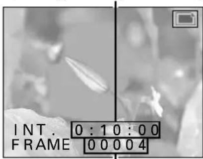
Remaining number of images Still Image Interval Shooting Screen
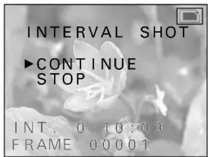
Still Image Interval Shooting Completion Screen
HELP
If "ERROR" is displayed when the power is turned on
- If the interval shooting was not completed properly due to a reason such as the battery power running out, this error message will appear when the power is turned back on. (This message tells you that the interval shooting was not ended properly.) Press the MODE button to enter the still image shooting mode.
NOTE
- When performing interval shooting, if necessary, use a tripod to prevent the digital disk camera from moving and ensure the same camera angle.

Error display
Video clip interval shooting
Video clip interval shooting is a special shooting technique that allows you to create a video clip by capturing the images for each frame separately and in set intervals. The audio is not recorded during the interval shooting, so the completed video clip will have no sound.
Example: Making a five-second video clip by capturing one frame every 20 seconds (for frame rate 30f, the interval shooting will take 50 minutes).

flowchart
graph LR
    A["1 frame captured"] --> B["1 frame captured"]
    B --> C["20-second interval 20-second interval"]
    C --> D["1 frame captured"]
    D --> E["1 frame captured"]
    E --> F["5-second playback"]
Preparation
- Set the CAMERA/PLAY switch to "CAMERA."
- Turn the mode selector dial to 📄 to select the video clip shooting mode.
1 Press the MODE button.
● The Video Clip Shooting Setting Screen appears.
- The resolution and frame rate settings cannot be changed in the middle of interval shooting. If necessary, change these settings as desired before proceeding to step 2.
2 Press ▲ or ▼ on the arrow button to select the special shooting menu.
● The special shooting menu appears.

Special shooting menu Video Clip Shooting Setting Screen
3 Press ▶ on the arrow button to select the INT icon.
For interval shooting: Select INT
For normal shooting: Select NORM
For animation shooting: Select ANM
NOTE
- By fixing the settings for video clip interval shooting, the images of the slow changes in the subject over time are captured more accurately. If interval shooting is performed with the digital disk camera set to autofocus, program AE, and auto white balance, then each image may be captured with slightly different settings making each image slightly different. To avoid this, set AE lock (see page 92) and white balance lock (see page 96) and set the focus manually.
- With video clip interval shooting, audio is not recorded; you can use the self-timer (see page 80) function.
About the video clip length and the frame rate setting
- With video clip interval shooting, to make a one-second long video clip, you will need to capture 30 images if the frame rate setting is 30f and 15 images if the frame rat setting is 15f.
4 Press the SET button.
- The Video Clip Interval Shooting Setting Screen appears.
5 Set the interval shooting parameters.
- Set the interval between images at "INT." and the length of the final video clip at "DUR."
- The number of frames will change according to the video clip length and the frame rate setting. Use this value as a reference.
■ Performing the settings at the Video Clip Interval Shooting Setting Screen
To change a setting: Press ▲ or ▼
To move to the next item: Press ▶
To move to the previous item: Press ◀
To cancel the settings and return to the Shooting Setting Screen: Press the MODE button
- The interval can be set from 10 seconds to 9 hours 59 minutes 59 seconds.
- The length of the video clip can be between 1 and 999 frames, depending on the remaining disk space.
Shooting interval (hrs:min:sec)
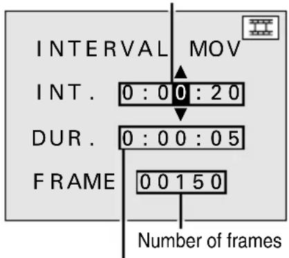
Length of video clip (hrs:min:sec)
Video Clip Interval Shooting Setting Screen
HELP
If "ERROR" appears at step 4
- This error message tells you that the temporary data for a video clip interval shooting or animation shooting (see page 107) already exists in the digital disk camera. Either save the temporary data or erase it (see steps ② and ③ on page 105). To start a new video clip interval shooting, you will need to erase any existing temporary data.
If "ERROR" is displayed when the power is turned on
- If the interval shooting was not completed properly due to a reason such as the battery power running out, this error message will appear when the power is turned back on. (This message tells you that the interval shooting was not ended properly.) Press the MODE button, perform steps 1 to 4 on page 101, and then perform steps ② and ③ on page 105.
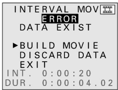
Video Clip Interval Shooting Error Screen

Error display
6
Press the SET button.
● The Video Clip Interval Shooting Ready Screen appears.
- To stop the interval shooting before it is completed, press the MODE button.
- The timer mark and the time until the next image is captured (hrs:min:sec) appear in the mode display panel.
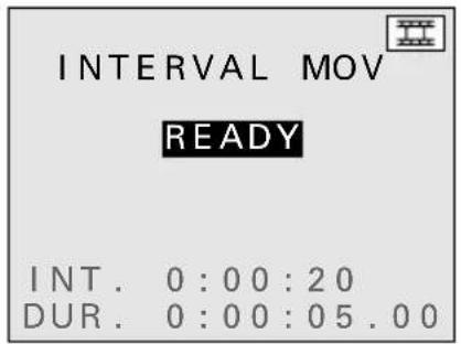
Video Clip Interval Shooting Ready Screen

Time until next frame is recorded (hrs:min:sec)
Mode display panel
7 Press the shutter release button.
- The video clip interval shooting begins and the first image is captured.
● The monitor turns off. To turn the monitor back on, press the power button. To turn it back off, press the power button again. - When the time set in step 5 elapses, the next image is captured.
● The remaining video clip length and number of frames displayed in the monitor will change as shown below.
Frame rate is set to 30f: Decreases one frame at a time Frame rate is set to 15f: Decreases two frames at a time - When the set video clip length is captured, the interval shooting is completed.
- To pause or end the interval shooting beforehand, perform the operations on the next page.
Shooting interval (hrs:min:sec)

Remaining length of video clip (hrs:min:sec.frames)
Video Clip Interval
Shooting Screen
- If the interval shooting is completed while the monitor is turned on, "PROCESSING" appears while the video clip is created from the captured images. When that is completed, the Video Clip Shooting Setting Screen appears.
- If the interval shooting is completed while the monitor is turned off, the video clip is not created and the digital disk camera automatically turns off. Afterward, be sure to create the video clip with the captured images (see page 106).
- The digital disk camera cannot be turned off during interval shooting. You will need to first end the interval shooting (see page 105) and then turn off the digital disk camera.
- Once the video clip is created from the temporary data, the video clip can be viewed just as a normal video clip (see page 63). Check the video clip and then erase the temporary data (see page 106).

NOTE
- When performing interval shooting, if necessary, use a tripod and the remote control to capture images. This prevents the digital disk camera from moving and ensures the same camera angle.
■ Pausing or ending video clip interval shooting
① Press the power button to turn on the monitor and press the MODE button.
● The Video Clip Interval Shooting Completion Screen appears. When this screen appears, the timer stops and the interval shooting is paused.
② Press ▲ or ▼ to select the desired option.
CONTINUE: Resumes the interval shooting BUILD MOVIE: Uses the temporary data captured to create a video clip and ends the interval shooting
DISCARD DATA: Erases the temporary data captured and ends the interval shooting
EXIT: Stops the interval shooting

Video Clip Interval Shooting Completion Screen
③ Press the SET button.
- If you selected "CONTINUE," the interval shooting resumes.
- If you selected "BUILD MOVIE," "PROCESSING" appears and the temporary data is used to create a video clip. When this is completed, the video clip interval shooting is ended.
- If you selected "DISCARD DATA," the temporary data is erased. See step 2 on page 106.
- If you selected "EXIT," the interval shooting is stopped with the images captured stored as temporary data. In this condition you can perform all of the functions of the digital disk camera except for video clip interval shooting and animation shooting (see page 107). If you attempt to perform video clip interval shooting, the Video Clip Interval Shooting Error Screen (see page 102) will appear, and if you attempt to perform animation shooting, the Animation Shooting Error Screen (see page 109) will appear. Follow the instructions given for those screens.
Erasing the temporary data from video clip interval shooting
During video clip interval shooting, the images captured are stored in your digital disk camera as temporary data. After this data is used to create the video clip, it will be necessary to erase this data. Also, if you stop interval shooting before it is completed and create the video clip, it will also be necessary to erase the temporary data.
Preparation
- Display the Video Clip Interval Shooting Error Screen (see page 102) or the Video Clip Interval Shooting Completion Screen (see page 105).
1
Press ▲ or ▼ on the arrow button to select "DISCARD DATA" and press the SET button.
● The Erase Confirmation Screen appears.
- To create a video clip from the temporary data, select "BUILD MOVIE" and press the SET button.
2
Press ▲ on the arrow button to select "YES" and press the SET button.
- "ERASING" appears.
- When the erasing is completed, the Video Clip Shooting Setting Screen appears.

Video Clip Interval Shooting Completion Screen

Erase Confirmation Screen
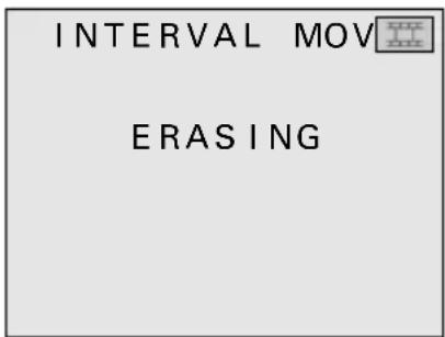
Erasing Screen
NOTE
- Even after the temporary data is used to create a video clip, it still remains and is not erased. (Your digital disk camera is programmed to not automatically erase the temporary data.)
- Since the temporary data is not a video clip, it will not appear in the Folder Information Screen (see page 118) or the Folder Erase All Confirmation Screen (see page 151) as a video clip. Be aware of this when erasing all the data in a folder or formatting a disk.
ANIMATION SHOOTING
Animation shooting is a special shooting technique that allows you to create a video clip by capturing the images for each frame separately with the shutter release button. This allows you to capture the images when you want based on the movement of the subject or the changes that you make to the subject. For example, you can gradually change the shape of a clay figure as you capture the images to make a video clip where the clay figure appears to be moving by itself. The audio is not recorded during the animation shooting, so the completed video clip will have no sound.
Animation shooting

flowchart
graph LR
    A["3D Object"] --> B["2D Object"]
    B --> C["1D Object"]
    C --> D["3D Object"]
    D --> E["2D Object"]
Capture one frame at a time
Preparation
- Set the CAMERA/PLAY switch to "CAMERA."
- Turn the mode selector dial to 📄 to select the video clip shooting mode.
1 Press the MODE button.
● The Video Clip Shooting Setting Screen appears.
- The resolution and frame rate settings cannot be changed in the middle of animation shooting. If necessary, change these settings as desired before proceeding to step 2.
2 Press ▲ or ▼ on the arrow button to select the special shooting menu.
● The special shooting menu appears.
3 Press ▶ on the arrow button to select the ANM icon.
For animation shooting: Select ANM
For normal shooting: Select NORM
For interval shooting: Select INT
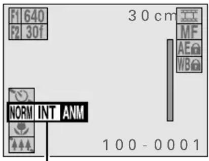
Special shooting menu Video Clip Shooting Setting Screen
NOTE
- By fixing the settings for animation shooting, the images of the different frames shot over time are captured more accurately. If animation shooting is performed with the digital disk camera set to autofocus, program AE, and auto white balance, then each image may be captured with slightly different settings making each image slightly different. To avoid this, set AE lock (see page 92) and white balance lock (see page 96) and set the focus manually.
- With animation shooting, audio is not recorded; you cannot use the self-timer (see page 80) function.
4 Press the SET button.
● The Animation Shooting Ready Screen appears.
- To stop animation shooting, press the MODE button.
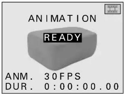
Animation Shooting Ready Screen
5 Press the shutter release button.
● The image for the first frame is captured.
- If the digital disk camera is left for three (when using the battery pack) or thirty (when using the AC adapter/charger) minutes after the first frame is captured, the monitor will automatically turn off. To turn the monitor back on, press the power button. To turn it back off, press the power button again.
● The recording time until now and number of frames displayed in the monitor will change as shown below.
Frame rate is set to 30f: Increases one frame at a time
Frame rate is set to 15f:
Increases two frames at a time
- The maximum number of frames that can be captured can be up to 999 frames, depending on the remaining disk space.
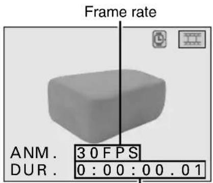
Recording time until now (Total playback time hrs:min:sec.frames)

Number of frames after completion
Mode display panel
HELP
If "ERROR" appears at step 4
- This error message tells you that the temporary data for an animation shooting or video clip interval shooting (see page 101) already exists in the digital disk camera. Either save the temporary data or erase it (see ② and ③ of step 7 on page 110). To start a new animation shooting, you will need to erase any existing temporary data.
NOTE
- When performing animation shooting, if necessary, use a tripod and the remote control to capture images. This prevents the digital disk camera from moving and ensures the same camera angle.

Animation Shooting Error Screen
6
Move the subject as desired.
- Repeat steps 5 and 6 until your animation shooting is completed.
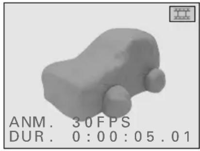
natural_image
3D rendered object resembling a vehicle or abstract shape with rounded ends, no visible text or symbols on the object itself.7
Complete the animation shooting.
① Press the power button to turn on the monitor and press the MODE button.
- The Animation Shooting Completion Screen appears.
② Press ▲ or ▼ to select the desired option.
CONTINUE: Resumes the animation shooting
BUILD MOVIE: Uses the temporary data captured to create a video clip and ends the animation shooting
DISCARD DATA: Erases the temporary data captured and ends the animation shooting
EXIT: Stops the animation shooting
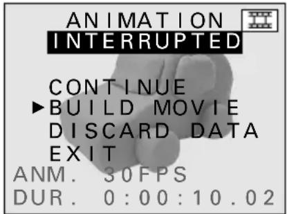
Animation Shooting Completion Screen
③ Press the SET button.
- If you selected "CONTINUE," the animation shooting resumes.
- If you selected "BUILD MOVIE," "PROCESSING" appears and the temporary data is used to create a video clip. When this is completed, the animation shooting is ended.
- If you selected "DISCARD DATA," the temporary data is erased. See step 2 on page 111.
-
If you selected "EXIT," the animation shooting is stopped with the images captured stored as temporary data. In this condition you can perform all of the functions of the digital disk camera except for animation shooting and video clip interval shooting (see page 101). If you attempt to perform animation shooting, the Animation Shooting Error Screen (see page 109) will appear, and if you attempt to perform video clip interval shooting, the Video Clip Interval Shooting Error Screen (see page 102) will appear. Follow the instructions given for those screens.
-
The digital disk camera cannot be turned off during animation shooting. You will need to first end the animation shooting and then turn off the digital disk camera.
- Once the video clip is created from the temporary data, the video clip can be viewed just as a normal video clip (see page 63). Check the video clip and then erase the temporary data (see page 111).
Erasing the temporary data from animation shooting
During animation shooting, the images captured are stored in your digital disk camera as temporary data. After this data is used to create the video clip, it will be necessary to erase this data. Also, if you stop animation shooting before it is completed and create the video clip, it will also be necessary to erase the temporary data.
Preparation
- Display the Animation Shooting Error Screen (see page 109) or the Animation Shooting Completion Screen (see page 110).
1
Press ▲ or ▼ on the arrow button to select "DISCARD DATA" and press the SET button.
● The Erase Confirmation Screen appears.
- To create a video clip from the temporary data, select "BUILD MOVIE" and press the SET button.
2
Press ▲ on the arrow button to select "YES" and press the SET button.
- "ERASING" appears.
- When the erasing is completed, the Video Clip Shooting Setting Screen appears.

Animation Shooting Completion Screen
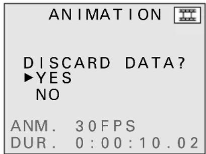
Erase Confirmation Screen

Erasing Screen
NOTE
- Even after the temporary data is used to create a video clip, it still remains and is not erased. (Your digital disk camera is programmed to not automatically erase the temporary data.)
- Since the temporary data is not a video clip, it will not appear in the Folder Information Screen (see page 118) or the Folder Erase All Confirmation Screen (see page 151) as a video clip. Be aware of this when erasing all the data in a folder or formatting a disk.
CUSTOM SETTING
You can customize the settings of your digital disk camera such as the manual mode settings, exposure metering method, ISO sensitivity, folder settings, shutter sounds, and remote control to make your digital disk camera work as you like.
Storing and initializing the manual mode settings
You can set whether or not your digital disk camera stores the macro focus (see page 72), digital zoom (see page 75), exposure correction (see page 87), and manual mode (see page 88) settings after the digital disk camera is turned off. Your digital disk camera is initially set to store these settings. To have your digital disk camera return to its initial settings each time it is turned off, make the proper settings by following the procedure below.
Preparation
- Turn the mode selector dial to 📋 to display the Option Screen.
1 Press the arrow button to select the camera icon and press the SET button.
● The Camera Setting Screen appears.
2 Press ▲ or ▼ on the arrow button to select the hold settings menu.
● The hold settings menu appears.
3 Press ▶ on the arrow button to select 📋 or 🏠.
To store settings even after turned off: Select 🚪 To return to initial settings after turned off: Select 🚪
4 Press the SET button.
- This completes the setting of whether or not to store manual mode and other settings.
- To return to the Option Screen, press the MODE button.
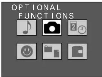
Option Screen

Hold settings menu Camera Setting Screen
NOTE
- Even if 🖼️ is selected for the hold settings menu, if all of the conditions given below are met, the settings will be initialized.
- The battery pack is removed (or it runs out of power).
• The AC adapter/charger is not connected. - The clock backup battery is removed (or it runs out of power) (see page 23).
Setting the exposure metering
Your digital disk camera is capable of two types of exposure metering: by dividing up the screen and calculating the total amount of light by adding up each division (matrix metering) or by measuring the amount of light in the central portion of the screen only (center-weighted metering). Your digital disk camera is initially set to use matrix metering for determining the proper exposure settings. To have your digital disk camera use center-weighted metering, make the proper settings by following the procedure below.
Preparation
- Turn the mode selector dial to 📁 to display the Option Screen.
1 Press the arrow button to select the camera icon and press the SET button.
● The Camera Setting Screen appears.
2 Press ▲ or ▼ on the arrow button to select the exposure metering menu.
● The exposure metering menu appears.
3 Press ▶ on the arrow button to select ☐ or ☐.
For matrix metering: Select ☐
For center-weighted metering: Select ☐
4 Press the SET button.
● This completes the exposure metering setting.
- To return to the Option Screen, press the MODE button.
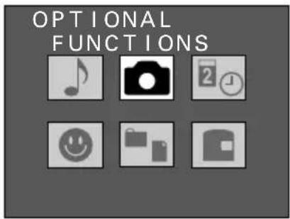
Option Screen
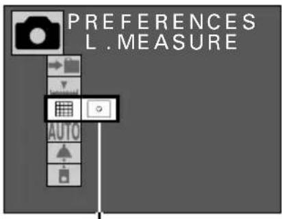
Exposure measurement menu Camera Setting Screen
Setting the ISO sensitivity
The initial settings for your digital disk camera have the digital disk camera set the ISO sensitivity automatically according to the brightness of the subject. However, you can fix the ISO sensitivity to ISO 100, 200, or 400 equivalency.
Preparation
- Turn the mode selector dial to 📋 to display the Option Screen.
1 Press the arrow button to select the camera icon and press the SET button.
● The Camera Setting Screen appears.
2 Press ▲ or ▼ on the arrow button to select the ISO menu.
- The ISO menu appears.
3 Press ▶ on the arrow button to select the desired ISO sensitivity.
AUTO: For having the ISO sensitivity set automatically (between ISO 100 and 200 equivalency)
100: Sets the sensitivity equivalent to ISO 100
200: Sets the sensitivity equivalent to ISO 200
400: Sets the sensitivity equivalent to ISO 400
4 Press the SET button.
● This completes the ISO sensitivity setting.
- To return to the Option Screen, press the MODE button.

Option Screen
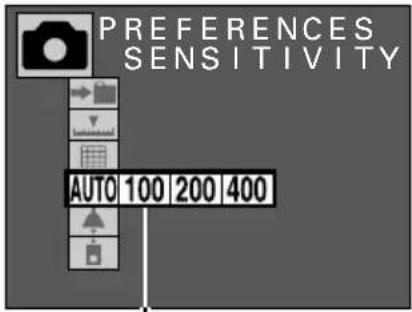
ISO menu
Camera Setting Screen
NOTE
- If the ISO sensitivity is set to 400, be aware that pattern noise or random noise may appear in captured images.
Dealing with the folder settings
The initial settings for your digital disk camera have all files (i.e. images, video clips, and audio recordings) stored in the folder number 100 (see page 148). When the number of files increases and exceeds a certain amount, a new folder is automatically created (folder number 101 and so on) and the new files are stored in this folder (see page 168).
Your digital disk camera also allows you to create new folders. By creating new folders, you can separate images and files into different folders for classification and also move files from one folder to another. By creating folders, your files can be neatly organized when they become too many to commit to memory.
Creating a folder
Preparation
- Turn the mode selector dial to 📋 to display the Option Screen.
1 Press the arrow button to select the camera icon and press the SET button.
● The Camera Setting Screen appears.
2 Select the folder icon → and press the SET button.
● The Folder Setting Screen appears.

Option Screen
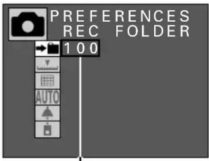
Current folder number
Camera Setting Screen
3 Press ▲ on the arrow button to select "NEW" and press the SET button.
● The Create Folder Confirmation Screen appears.

Folder Setting Screen
4 Select "YES" and press the SET button.
- The new folder will be assigned a number sequentially starting with 101 (i.e. 100 101 102 ·s 999 ). The number assigned to a folder cannot be set manually.
- After the new folder is created, you return to the Camera Setting Screen and subsequent files recorded by your digital disk camera will be stored in the new folder.

New folder number
Create Folder Confirmation Screen
NOTE
About the folder to which files are saved and the folder from which files are played
- Your digital disk camera allows you to create multiple folders so that you can organize your files into the different folders. The setting of which folder to save files to and which folder to play files from is done separately so be careful not to confuse the two.
Setting the save folder: Go to Folder Setting Screen (see page 117).
Setting the playback folder: There are two methods (the folder for saving will not change even if the folder for playing back files is changed).
- Select the desired folder at the Folder Information Screen (see page 118) and press the SET button.
- Change folders at the Skip File Screen (see pages 55, 60, 65).
- If you turn off the digital disk camera while it is in a playback mode and then turn it back on, a file from the previously selected playback folder will be displayed. If you perform any shooting, those files will be saved to the save folder selected at the Folder Setting Screen. At this time, if you return to the playback mode, files from the folder to which you just saved files will be displayed.
Example:
1 Select the folder to save files (the save folder) at the Folder Setting Screen (see page 117).
(Example: Set folder number 103)
- If shooting is performed, those files will be saved to folder number 103.
② Change to playback mode without turning off the digital disk camera.
- Files in folder number 103 are played back.
③ Change the playback folder at the Folder Information Screen (see page 118).
(Example: Set folder number 101)
④ Perform shooting.
● The files are saved to folder number 103.
⑤ Change to playback mode.
- Files in folder number 103 are played back.
Selecting a folder
Preparation
- Turn the mode selector dial to 📋 to display the Option Screen.
1 Press the arrow button to select the camera icon and press the SET button.
● The Camera Setting Screen appears.

Option Screen
2 Select the folder icon → and press the SET button.
● The Folder Setting Screen appears.
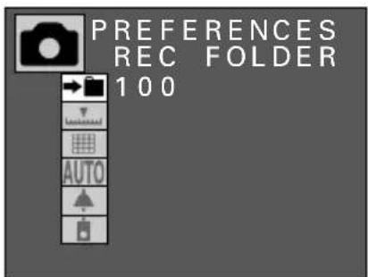
Camera Setting Screen
3 Press ▲ or ▼ to select the desired folder and press the SET button.
- This sets to which folder subsequent files are saved (the save folder).
- You return to the Camera Setting Screen.
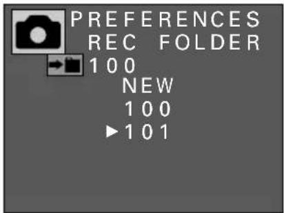
Folder Setting Screen
NOTE
- Changing the playback folder is performed at the Skip File Screen (see pages 55, 60, 65) or Folder Information Screen (see page 118). The save folder can only be changed at the Folder Setting Screen shown above.
Viewing the folder information
Follow the procedure below to view the number and types of files stored in folders and the date folders were created.
Preparation
- Turn the mode selector dial to 📋 to display the Option Screen.
1
Press the arrow button to select the folder information icon □ and press the SET button.
● The Folder Information Screen appears.
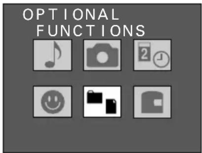
Option Screen

Folder list
Folder Information Screen
2
Press ▲ or ▼ on the arrow button to select the desired folder.
● The information for the selected folder appears.
- To return to the Option Screen, press the MODE button.
- If you press the SET button while the information of a folder is being displayed, that folder will become the folder from which files are played back (the playback folder).
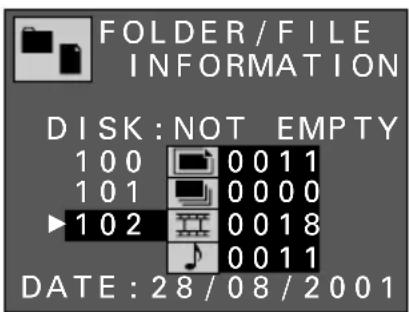
NOTE
- The playback folder can also be changed at the Skip File Screen (see pages 55, 60, 65). The save folder is changed at the Folder Setting Screen (see page 117).
- Up to 900 folders (folder numbers 100 to 999) can be created on one disk.
- Temporary video clip interval shooting data (see page 106) and temporary animation shooting data (see page 111) are not video clips and will not show up as video clip files. Be aware of this when erasing all the data in a folder or formatting a disk.
Setting the shutter sound
Your digital disk camera allows you to set whether or not a shutter sound will be heard when the shutter release button is pressed. Moreover, in addition to the camera sound that is the initial setting for the shutter sound, it also allows you to change the shutter sound to other sounds that you have recorded.
Setting whether or not to play the shutter sound
Follow the procedure below to set whether or not a shutter sound will be heard when you press the shutter release button.
Preparation
- Turn the mode selector dial to 📋 to display the Option Screen.
1 Press the arrow button to select the camera icon and press the SET button.
● The Camera Setting Screen appears.
2 Press ▲ or ▼ on the arrow button to select the shutter sound menu.
● The shutter sound menu appears.
3 Press ▶ on the arrow button to select ▲ or ▲ and press the SET button.
To play the shutter sound: Select
To not play the shutter sound: Select
To change the shutter sound (see next page): Select
- This completes the setting of whether or not to play the shutter sound.
- Even if ▲ is selected at the shutter sound menu, the shutter sound will not be played when filming a video clip.
- To return to the Option Screen, press the MODE button.

Option Screen
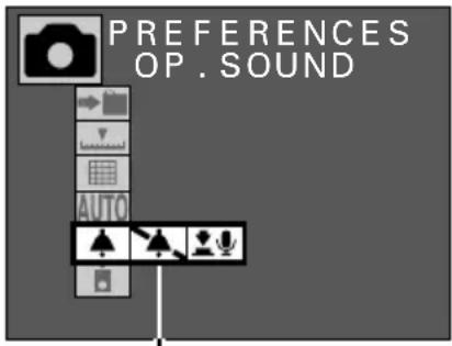
Shutter sound menu Camera Setting Screen
NOTE
To adjust the volume of the shutter sound
- At the Audio Recording Screen (see page 70), select the audio recording icon 📄 and press ◀ or ▶ to adjust the volume. The volume for playing back files will also be adjusted.
Changing the shutter sound
Follow the procedure below to record a new shutter sound using the microphone of the digital disk camera and set that recording as the shutter sound.
Preparation
- Turn the mode selector dial to 📋 to display the Option Screen.
1
Press the arrow button to select the camera icon and press the SET button.
● The Camera Setting Screen appears.
2
Press ▲ or ▼ on the arrow button to select the shutter sound menu.
● The shutter sound menu appears.
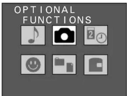
Option Screen
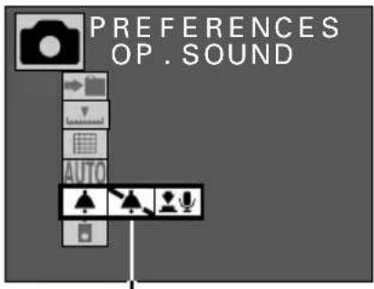
Shutter sound menu Camera Setting Screen
3
Press ▶ on the arrow button to select 🏠 and press the SET button.
● The Shutter Sound Screen appears.
MIC: To record a sound using the microphone
FILE: To use a stored audio recording
DEFAULT: To return to the initial setting
- You can press the shutter release button to hear the currently selected shutter sound.
- "MIC" is selected initially.

Shutter Sound Screen
4 Press the SET button.
● The Shutter Sound Recording Ready Screen appears.

Shutter Sound Recording Ready Screen
5 Press the shutter release button.
- Recording begins.
- Up to a maximum of five seconds can be recorded.
- To stop the recording before five seconds elapses, press the shutter release button.
- When recording is completed, "COMPLETE" appears and you return to the Shutter Sound Screen.
- At this time, you can press the shutter release button to hear the newly recorded shutter sound.
● The recorded sound file is stored on the disk in the digital disk camera (see page 148). - To return to the Option Screen, press the MODE button.
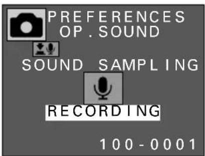

NOTE
- If a long shutter sound is set, the time from when the shutter release button is pressed until when the image is captured will become longer.
- In addition to recordings made using the microphone, you can also use the software included in the SANYO Software Pack to set sound files saved in your computer.
- Any silent portions at the beginning or end of the sound file will be cut and not used as the shutter sound (provided there is no background noise). In the example below, only the portion with sound is used as the shutter sound so the sound will be heard the moment the shutter release button is pressed.
0 1 second 2 seconds 3 seconds 4 seconds 5 seconds
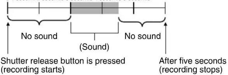
Selecting the shutter sound
Follow the procedure below to set a recording made using the microphone or one saved in your computer as the shutter sound. (Read the instruction manual included with the SANYO Software Pack.)
Preparation
- Turn the mode selector dial to 📋 to display the Option Screen.
1 Press the arrow button to select the camera icon and press the SET button.
● The Camera Setting Screen appears.
2 Press ▲ or ▼ on the arrow button to select the shutter sound menu.
● The shutter sound menu appears.
3 Press ▶ on the arrow button to select 🏠️ and press the SET button.
● The Shutter Sound Screen appears.
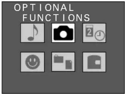
Option Screen

Shutter sound menu Camera Setting Screen
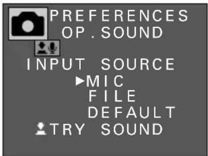
Shutter Sound Screen
4 Press ▼ on the arrow button to select "FILE" and press the SET button.
● The Shutter Sound Selection Screen appears.
- A list of the sound files stored in the sound folder is displayed.
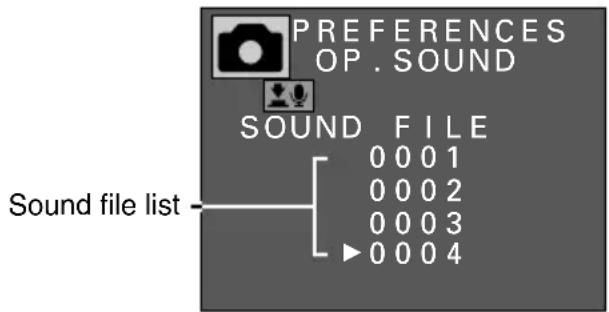
Shutter Sound Selection Screen
5 Press ▲ or ▼ on the arrow button to select the desired sound file and press the SET button.
- The selected sound file is set as the shutter sound and you return to the Shutter Sound Screen.
- For normally recorded audio recordings (see page 68), only the first five seconds are used for the shutter sound.
- You can press the shutter release button to hear the currently selected shutter sound.
- To return to the Option Screen, press the MODE button.
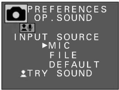
Shutter Sound Screen
NOTE
- To return the shutter sound to its initial setting, select "DEFAULT" at the Shutter Sound Screen and press the SET button.
Setting the remote control operation
Follow the procedure below to set whether or not you will use the remote control.
Preparation
- Turn the mode selector dial to 📋 to display the Option Screen.
1 Press the arrow button to select the camera icon and press the SET button.
● The Camera Setting Screen appears.
2 Press ▲ or ▼ on the arrow button to select the remote control menu.
● The remote control menu appears.
3 Press ▶ on the arrow button to select the desired remote control mode.
To use the remote control: Select
To not use the remote control: Select
4 Press the SET button.
- This completes the setting of whether or not you will use the remote control.
- Refer to page 36 for information regarding the use of the remote control.
- To return to the Option Screen, press the MODE button.

Option Screen

Remote control menu Camera Setting Screen
NOTE
- The power save function (see page 35) will differ depending on the remote control menu setting.
☐: If the digital disk camera is left for the specified amount of time, it enters the power save mode and then turns off.
☐: If the digital disk camera is left for the specified amount of time, it turns off without entering the power save mode.
SETTING THE REMAINING DISK SPACE DISPLAY FORMAT
Your digital disk camera allows you to set how the remaining disk space is displayed in the mode display panel. Follow the procedure below to set the desired remaining disk space display format.
Preparation
- Turn the mode selector dial to 📋 to display the Option Screen.
1 Press the arrow button to select the disk icon ☐ and press the SET button.
● The Disk Tools Screen appears.
- The remaining disk space display format menu is selected initially.
2 Press ▶ on the arrow button to select the desired remaining disk space display format.
- Select the format to use for displaying the remaining disk space.
To display the remaining number of images/remaining recording time available: Select Ⓞ/P
To display the remaining percentage of disk space: Select %
To display the remaining disk space in megabytes: Select MB

Option Screen

Remaining disk space display format menu Disk Tools Screen
3 Press the SET button.
● This completes the setting of the remaining disk space display format.
● To return to the Option Screen, press the MODE button.
● The display of the remaining disk space will appear as shown below.
| ○/P selected | % selected | MB selected | |
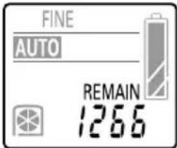 Remaining number of images (still image and sequential shot shooting) Remaining number of images (still image and sequential shot shooting) | 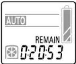 Remaining recording time (video clip shooting) Remaining recording time (video clip shooting) | 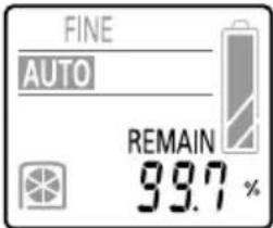 Remaining percentage Remaining percentage |  Remaining disk space Remaining disk space |
NOTE
Even after formatting the remaining disk space will not be 730 megabytes or 100%
- An iD PHOTO disk has 356,832 sectors of 2,048 bytes each for a total capacity of 730,791,936 bytes. However, the digital disk camera calculates one megabyte as 1,048,574 bytes for the display of the remaining disk space (in megabytes or percentage) so the display is a small amount less than the actual value.
ADDING A VOICE MEMO TO AN IMAGE
Adding a voice memo
You can add a voice memo to a still image captured in the still image mode, an image saved after magnifying, a compound image, or a copied image.
Preparation
- Set the CAMERA/PLAY switch to "PLAY."
- Turn the mode selector dial to 📄 to select the still image playback mode.
1 Display the image to which you wish to add a voice memo.
2 Press the MODE button to display the Playback Setting Screen.
3 Press ▲ or ▼ on the arrow button to select the edit still image icon 📄.

natural_image
Group of uniformed personnel standing in formation with flags, no visible text or symbols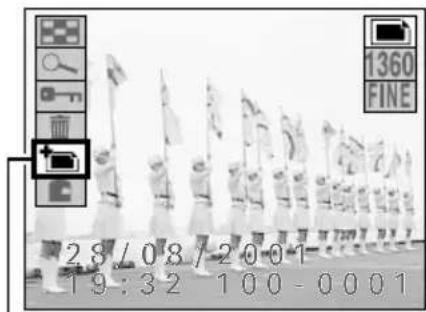
Edit still image icon
Playback Setting Screen
4 Press the SET button.
● The Edit Image Screen appears.
- At this time, you can still press ◀ or ▶ or turn the control dial to select another image.
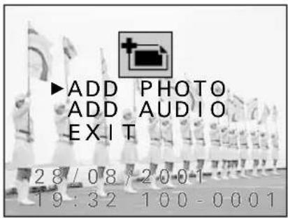
Edit Image Screen
NOTE
- If an image is protected, you cannot add a voice memo. To add a voice memo, first remove the protection (see page 152) and then add the voice memo.
5
Press ▼ on the arrow button to select "ADD AUDIO" and press the SET button.
- The digital disk camera is now ready to add the voice memo.
6
Press the shutter release button.
- The voice memo recording starts. Talk into the microphone on the digital disk camera. A maximum of up to ten seconds can be recorded. While the voice memo is being recorded, "RECORDING" appears. To stop the recording before the ten seconds elapses, press the shutter release button again.
- When recording is finished, "COMPLETE" appears and you return to the Edit Image Screen.
- To record voice memos for other images, press ◀ or ▶ or turn the control dial to select the desired image and repeat steps 5 and 6.
- To return to the Playback Setting Screen, press the MODE button, or select "EXIT" and press the SET button.
- For images with a voice memo, the voice memo mark will appear in the Playback Setting Screen.
- To listen to the voice memo, press the MODE button to exit the Playback Setting Screen and then press the SET button.
- To adjust the volume, see "Adjusting the volume" on page 70.
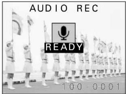
Shutter release button

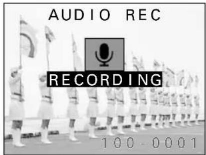
Voice memo mark

Playback Setting Screen
NOTE
● Voice memos can also be recorded when the image is captured (see page 78).
- After a voice memo has been added to an image, you can erase only the voice memo (see page 151). Also, when an image with a voice memo is erased, the attached voice memo is also erased.
- If a voice memo is added to an image that already has a voice memo, the new voice memo will replace the previous one.
- Besides using the built-in microphone, you can also record the voice memo by connecting the supplied microphone to the MIC input terminal. Be aware that the built-in microphone will not work when a microphone is connected to the MIC input terminal (see page 49).
HELP
If "DISK FULL" appears
- This indicates that there is not enough empty space on the disk to add a voice memo. If you wish to add a voice memo, you must first erase some data in order to free up some space (see page 149).
ADDING AN IMAGE TO ANOTHER IMAGE
Adding an image (compound image function)
You can insert an image into a frame set in a still image captured in the still image mode, an image saved after magnifying, or a copied image, and create a compound image consisting of an image within an image. This function can be used for simple image editing such as adding a picture of a face to a name card.
Compound image creation process
① Display the image for the background
② Set the size of the image to be added
③ Set the position of the image to added
④ Capture the image to be inserted (press the shutter release button)
● The compound image is created.
● The original image for the background remains.
Check the focus setting before creating the compound image
If the subject that you will shoot for the compound image is close (from 3 to 60~cm away), put the digital disk camera in the still image shooting mode and set the focus to either the macro focus mode or the total range focus mode (see page 72).
Preparation
- Set the CAMERA/PLAY switch to "PLAY."
- Turn the mode selector dial to 📄 to select the still image playback mode.
Display the image for the background
1 Display the still image for the background.
2 Press the MODE button to display the Playback Setting Screen.

Playback Setting Screen
3 Press ▲ or ▼ on the arrow button to select the edit still image icon and press the SET button.
● The Edit Image Screen appears.
- "ADD PHOTO" is selected initially.

Edit Image Screen
4 Press the SET button.
- The guidelines to set the frame for the image to be inserted appear (white lines).

natural_image
Group of uniformed personnel marching in formation with flags, no visible text or symbolsSet the size of the image to be added
To set the size of the frame, first set the top left corner of the frame (first point) and then the bottom right corner of the frame (second point). The position of the frame is set later.
First point Second point

natural_image
Black-and-white photo of uniformed marching soldiers holding flags, no visible text or symbols5 Use the arrow button to set the first point.
- Use ▲ and ▼ to move the horizontal guideline vertically.
- Use ◀ and ▶ to move the vertical guideline horizontally.
- Press and hold an arrow to move the guidelines continuously in that direction and release the arrow to stop the guideline.
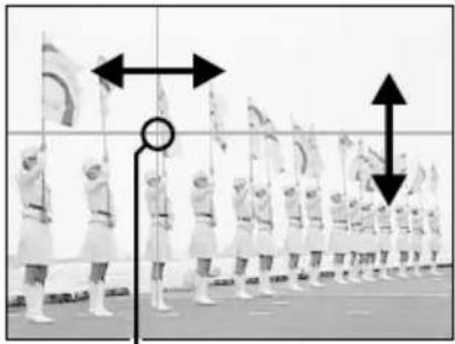
natural_image
Group of uniformed personnel marching in formation with directional arrows indicating movement (no text or symbols)First point
6 Press the SET button.
● The first point is set where the guidelines intersect.
● The guidelines for setting the second point appear.
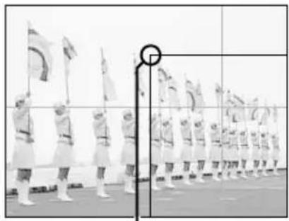
natural_image
Black-and-white photo of uniformed personnel marching in formation with flags, no visible text or symbolsFirst point location
7 Use the arrow button to set the second point and press the SET button.
- The size of the frame is now set by the rectangle formed by the two selected points.
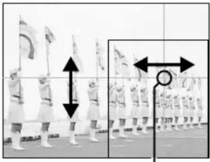
natural_image
Black-and-white photo of uniformed marching soldiers in formation, with one soldier standing upright and another holding a flag; no visible text or symbols.Second point
Set the position of the image to added
8
Use the arrow button to set the position of the frame where the image is to be inserted.
- Use the arrow button to move the frame to the position where you want the image to be inserted.
- To change the frame size, press the MODE button to return to step 5 and reset the first point.
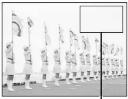
natural_image
Group of uniformed personnel marching in formation with flags, no visible text or symbolsFrame
9
Press the SET button.
● The image appears in the frame.

natural_image
Group of uniformed personnel marching in formation with flags, one person visible in the background (no text or symbols)Added image
Capture the image to be inserted
10
Compose the image as desired and press the shutter release button to capture the image.
● After the image is captured, you return to the Edit Image Screen.
- The compound image is completed and is saved as the last still image.
- To return to the Playback Setting Screen, press the MODE button, or select "EXIT" and press the SET button.
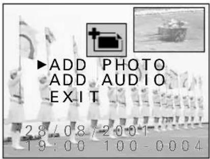
Edit Image Screen
HELP
If "DISK FULL" appears
- This indicates that there is not enough empty space on the disk to save the compound image. An amount of free space equal to the size of the background image is required. If you wish to save the image, you must first erase some data in order to free up some disk space (see page 149).
NOTE
- When capturing the image to be inserted, the flash and self-timer cannot be used. Also, even if the shutter sound menu setting is ▲ (see page 119), the shutter sound will not be heard.
- The compression setting for the compound image is NORM. (The resolution will not be changed.)
ENLARGING (ZOOMING IN) THE IMAGE
Captured images can be enlarged for viewing during playback and the enlarged image can be saved as a still image.
1 Display the image that you want to enlarge.
- See “Playing back still images” on page 52, “Playing back sequential shots” on page 57, or “Playing back video clips” on page 63.
2 Press the MODE button to display the Playback Setting Screen.
3 Press ▲ or ▼ on the arrow button to select the playback zoom icon 🔍 and press the SET button.
- The image is enlarged and the center portion of the image appears.
● The playback zoom indicator appears in the right side of the monitor. - You can use the arrow button to scroll through the image and display a different portion.

Playback zoom icon
Playback Setting Screen
4 To further enlarge the image, press the SET button again.
- Each time the SET button is pressed, the image is enlarged.
- You can also turn the control dial to perform the same operation.
To enlarge: Turn clockwise.
To return to original size: Turn counter-clockwise.
- The maximum amount an image can be enlarged will depend on its resolution.
1360 resolution: Up to 7 magnifications
1024 resolution: Up to 6 magnifications
640 resolution: Up to 5 magnifications
320 resolution: Up to 4 magnifications
160 resolution: Up to 4 magnifications
- If the SET button is pressed when the image has been enlarged to its maximum amount, the image returns to its normal size.

natural_image
Black-and-white photo of potted plants in a row beside a wooden cart, with a magnifying glass icon on the right (no text or symbols visible)Playback zoom indicator Zoomed Image Screen
5 Press the shutter release button to save the magnified portion of the image being displayed as a separate still image.
NOTE
- As the image is enlarged, the quality will become rougher.
- One frame of a video clip can be enlarged; however, a video clip cannot be played back while enlarged.
- For 1360 resolution, the maximum magnification amount is 21x.
HELP
If "DISK FULL" appears when you try to save the magnified image
- This indicates that there is not enough empty space on the disk to save the image. If you wish to save the image, you must first erase some data in order to free up some space (see page 149).
About the clipping and joining functions
Procedure for saving a portion of a video clip (clipping function)
You can select a specific scene of a video clip and save the portion up to and including that scene as a separate video clip or the portion from that scene to the end as a separate video clip.
① Display the video clip
② Set the scene where to clip
③ Select whether to save the beginning portion or ending portion
④ Save the portion as a video clip (press the SET button)
● The portion of the video clip is saved as a new video clip.
- The original video clip is left untouched. (The original video clip can be erased at this step.)
Procedure for joining two video clips together (joining function)
You can also join two video clips together and save them as one separate clip.
① Display the video clip to become the first portion
② Select the video clip to be last portion
③ Join the video clips (press the SET button)
● The video clips are joined and saved as a new video clip.
- The original video clips can be left untouched. (The original video clips can be erased at this step.)
NOTE
Concerning video clip editing
- Do not turn off the digital disk camera while you are editing video clips. If the power is turned off while editing video clips, not only will the editing not be properly completed, but the original video clip may also be erased.
- Note that as the number or size of the video clips increases, the disk installed in the digital disk camera may become full making it impossible to save the resulting video clip (the “DISK FULL” message will appear). In such a case, you will need to create space on the disk by erasing old video clips that are no longer necessary (see page 149).
Saving a portion of a video clip (clipping function)
Preparation
- Set the CAMERA/PLAY switch to "PLAY."
- Turn the mode selector dial to 📄 to select the video clip playback mode.
1 Display the video clip that you want to clip.
- See "Playing back video clips" on page 63.
2 Display the desired scene for clipping (see page 66).
- The portion of the video clip that will be saved (whether the beginning or ending portion) will include the selected scene.

3 Press the MODE button to display the Playback Setting Screen.
4 Press ▲ or ▼ on the arrow button to select the edit video clip icon 📁 and press the SET button.
● The Edit Video Clip Screen appears.
- "CLIPPING" is selected initially.

Playback Setting Screen

Edit Video Clip Screen
5 Press the SET button.
● The Clipping Screen appears.
- "CLIP FORMER" is selected initially.
6 Press ▲ or ▼ on the arrow button to select the portion of the video clip to be saved.
To save the beginning portion: Select "CLIP FORMER"
To save the ending portion: Select "CLIP LATTER"
7 Press the SET button.
● The Erase Original Confirmation Screen appears.
8 Press ▲ or ▼ on the arrow button to select whether or not to erase the original video clip when the new one is saved.
To erase the original video clip: Select "YES"
To not erase the original video clip: Select "NO"
9 Press the SET button.
- "PROCESSING" and then "LOADING" are displayed, and then you return to the Edit Video Clip Screen.
- The selected portion of the video clip is saved as a separate video clip.
- If "YES" was selected at step 8, the original video clip is erased as the selected portion is saved.
- To return to the Playback Setting Screen, press the MODE button, or select "EXIT" and press the SET button.
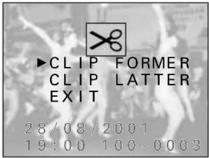
Clipping Screen

Erase Original Confirmation Screen
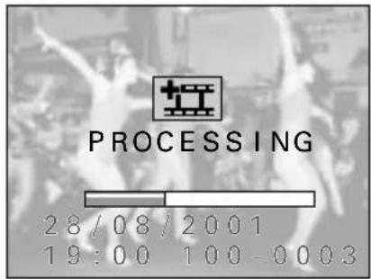
HELP
If "DISK FULL" appears
- This indicates that there is not enough available space on the disk to save the new video clip. For more information, refer to “Concerning video clip editing” on page 136.
If "BATTERY EMPTY" appears
- Video clip editing cannot be performed because the remaining charge in the battery pack is too low. Recharge the battery pack, replace it with a charged battery pack, or connect the AC adapter/charger and then perform the video clip editing.
NOTE
- Even if you select "YES" at step 8 and press the SET button, the original video clip will not be erased. If you want it to be erased if it is being protected, you need to first remove the protection (see page 152).
Joining two video clips together (joining function)
Preparation
- Set the CAMERA/PLAY switch to "PLAY."
- Turn the mode selector dial to 📄 to select the video clip playback mode.
1 Display the video clip that you want to join.
- See "Playing back video clips" on page 63.
- The second video clip will be attached to the end of this video clip after its last scene.

flowchart
graph LR
    A["Image: Group/Performance"] --> B["Video clip displayed now"]
    B --> C["Video clip to be attached"]
    C --> D["Filmstrip 1: Group/Performance"]
    C --> E["Filmstrip 2: Group/Performance"]
    C --> F["Filmstrip 3: Group/Performance"]
    C --> G["Filmstrip 4: Group/Performance"]
    C --> H["Filmstrip 5: Group/Performance"]
    C --> I["Filmstrip 6: Group/Performance"]
Video clip start Video clip end
2 Press the MODE button to display the Playback Setting Screen.
3 Press ▲ or ▼ on the arrow button to select the edit video clip icon 📁 and press the SET button.
● The Edit Video Clip Screen appears.
4 Press ▼ on the arrow button to select "JOINT."
5 Press the SET button.
● The 9-image Playback Screen for video clips appears.
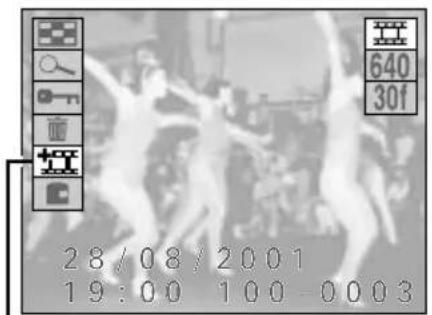
-Edit video clip icon
Playback Setting Screen
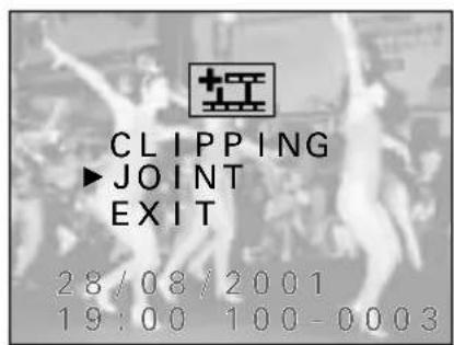
Edit Video Clip Screen
6 Press the arrow button to move the ➕ mark to the video clip that you want to attach.
7 Press the SET button.
● The Erase Original Confirmation Screen appears.
8 Press ▲ or ▼ on the arrow button to select whether or not to erase the original video clips when the new one is saved.
To erase the original video clips: Select "YES" To not erase the original video clips: Select "NO"
9 Press the SET button.
- "PROCESSING" and then "LOADING" are displayed, and then you return to the Edit Video Clip Screen.
- The two video clips are joined together and saved as a separate video clip.
- If "YES" was selected at step 8, the original video clips are erased as the joined video clip is saved.
- To return to the Playback Setting Screen, press the MODE button, or select "EXIT" and press the SET button.
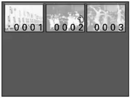
9-image Playback Screen

Erase Original Confirmation Screen
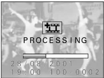
HELP
If "DISK FULL" appears
- This indicates that there is not enough available space on the disk to save the new video clip. For more information, refer to “Concerning video clip editing” on page 136.
If "SIZE ERROR" appears
- If the resolutions of the video clips are different, they cannot be joined. To join video clips together, select video clips recorded in the same resolution.
If "BATTERY EMPTY" appears
- Video clip editing cannot be performed because the remaining charge in the battery pack is too low. Recharge the battery pack, replace it with a charged battery pack, or connect the AC adapter/charger and then perform the video clip editing.
NOTE
- Even if you select "YES" at step 8 and press the SET button, the original video clip will not be erased if it is being protected. If you want it to be erased, you need to first remove the protection (see page 152).
- If the frame rates of the video clips being joined are different, the joined video clip will automatically become the lower frame rate of the two (see page 86).
- Video clips located in different folders cannot be joined. Move the video clips into the same folder before joining them (see page 153).
PROGRAMMED PLAYBACK
Your digital disk camera allows you to program the playback order so that you can play back a slide show of still images and video clips in any order you wish. Programming the playback allows you to play back still images and video clips together.
Creating a playback program
Follow the procedure below to set the order of the slide show. To do this you will create a program that specifies the files to play back. The program will then be saved onto the disk.
Preparation
- Move the write-protect tab on the disk to the write-enabled position (see page 155).
- Turn the mode selector dial to 📋 to display the Option Screen.
Caution
- Before creating a program, be sure to move the write-protect tab on the disk to the write-enabled position. If the tab is set to the write-protect position (the O mark), the program cannot be saved and the programmed playback cannot be performed.
1 Press the arrow button to select the program playback icon ⏻ and press the SET button.
- The Program Playback Selection Screen appears. To return to the Option Screen: Select "EXIT" To create a playback program: Select "VIEWER"
2 Press ▼ on the arrow button to select "VIEWER" and press the SET button.
- The Program Playback Setting Screen appears. - "PROGRAM" is selected initially.
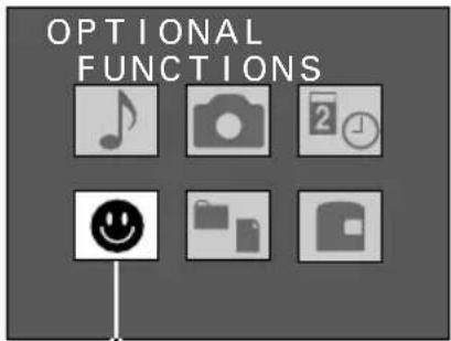
Program playback icon Option Screen
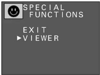
Program Playback Selection Screen
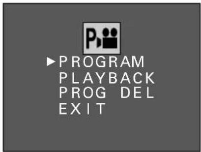
Program Playback Setting Screen
3 Press the SET button.
● The Compile Program Screen appears.
4 To change folders, select "FOLDER" and press ◀ or ▶ on the arrow button to select the desired folder number.
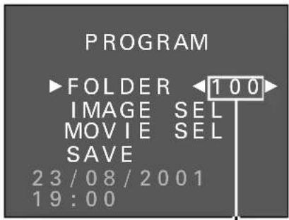
Folder number
Compile Program Screen
5 Press ▲ or ▼ on the arrow button to select “IMAGE SEL” or “MOVIE SEL.”
FOLDER: For selecting the folder where the files you want to play back are located
IMAGE SEL: For selecting still images to play back
MOVIE SEL: For selecting video clips to play back
SAVE: For saving the program

6 Press the SET button.
● The 9-image Playback Screen appears.
- If "NO IMAGE" appears, then there are no files of the type selected.
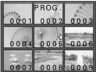
9-image Playback Screen
7 Select the files in the order you want them to be played back.
① Press the arrow button to move the ➕ mark to the desired file.
② Press the SET button.
- A check mark is placed on the selected file.
- To erase the check mark, press the SET button again.
- To change folders or type of file, press the MODE button to display the Compile Program Screen and repeat steps 4 to 6.
- Repeat ① and ② above to select the files for the playback program.
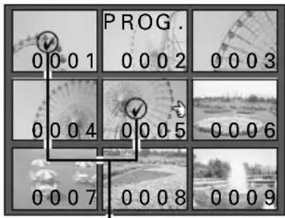
Check mark
8
Press the MODE button.
- You return to the Compile Program Screen.
● Proceed to steps 9 and 10. At this point, the program has not yet been saved.
9
Press ▼ on the arrow button to select "SAVE" and press the SET button.
- It will take a few moments for the program to be saved to the disk.
- Once saved, the Save Program Screen appears with the program number.
- In the example given on the right, the program was assigned the program number "0001."
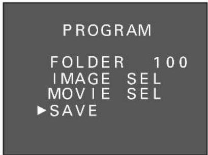
Compile Program Screen

Program number Save Program Screen
10
Press the SET button.
● The Compile Program Screen appears. The program has been compiled and saved.
- To return to the Program Playback Setting Screen, press the MODE button. To then return to the Program Playback Selection Screen, press the MODE button again, or select "EXIT" and press the SET button. To then return further back to the Playback Setting Screen, press the MODE button, or select "EXIT" and press the SET button.
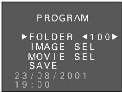
Compile Program Screen
Selecting a playback program and starting playback
Follow the procedure below to select a playback program and start the playback.
Preparation
- Turn the mode selector dial to 📋 to display the Option Screen.
1
Press the arrow button to select the program playback icon ⏻ and press the SET button.
- The Program Playback Selection Screen appears. To return to the Option Screen: Select "EXIT" To create a playback program: Select "VIEWER"

Program playback icon
Option Screen

Program Playback Selection Screen
2
Press ▼ on the arrow button to select "VIEWER" and press the SET button.
● The Program Playback Setting Screen appears.
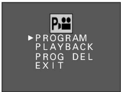
Program Playback Setting Screen
3
Press ▲ or ▼ on the arrow button to select "PLAYBACK" and press the SET button.
● The Program Selection Screen appears.
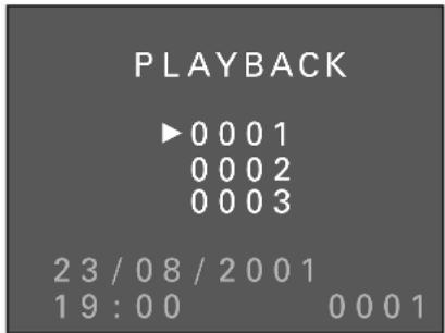
Program Selection Screen
4
Press ▲ or ▼ on the arrow button to select the desired program number and press the SET button.
● The playback program is selected and playback begins.
- To stop the playback, press the MODE button.
- When playback is completed, you return to the Program Playback Selection Screen.
Erasing a playback program
Follow the procedure below to erase a playback program that is no longer needed.
Preparation
- Turn the mode selector dial to 📋 to display the Option Screen.
1 Display the Program Playback Setting Screen.
● Perform steps 1 and 2 on page 144.
2 Press ▲ or ▼ on the arrow button to select "PROG DEL" and press the SET button.
● The Program Deletion Screen appears.
- If "NO PROGRAM" appears, there are no programs stored.
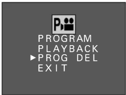
Program Playback Setting Screen
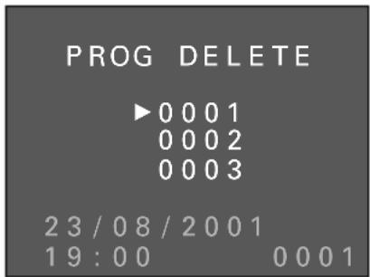
Program Deletion Screen
3 Press ▼ on the arrow button to select the program to be erased and press the SET button.
● The selected program is erased.
- If all programs are erased, you return to the Program Playback Setting Screen.
HANDLING DATA STORED ON THE DISK
How images, video clips, and audio recording are stored
Saving files recorded with your digital disk camera
- Saving files to a computer
Requires: Computer connecting cable and SANYO Software Pack (supplied), commercially available personal computer.
Advantages: The images are saved as data on the computer hard disk. They can then be processed or edited, sent over a network or the Internet, etc. for a wide range of applications.
For more information, see the instruction manual for the supplied SANYO Software Pack.
- Print out in high quality with a digital print service
The media used to store data recorded by your digital disk camera is the iD PHOTO disk. At the time of this print, most digital print services do not accept data on iD PHOTO disks, so you will need to copy the data onto another form of media. You can then take your image data to digital print service centers for high-quality print outs of your captured images. (Consult the service for more information.)
Advantages: You can receive high-quality printouts of the images you capture.
Caution: To print out a single shot from a sequential shot or a single scene from a video clip, you may need to first copy the data as a still image (see page 153). Be aware that if the image resolution is low, depending on the print size, the output image may not be high quality.
Data file formats
The format of the files saved on the disk and the method in which the file names are determined are explained below.
Still image files
Data format: JPEG or non-compressed YCbCr TIFF format (conforming to Exif Ver. 2.1) (see page 85)
File name structure: File name starts with SANY and will have the file extension jpg or tif.
Ex.: SANYoooo.jpg or SANYoooo.tif
The "oooo" represents a sequential number assigned automatically.
Voice memo data
Data format: WAVE format
File name structure: Same file name as the still image to which it is attached with the file extension wav.
Ex.: SANYoooo.wav
Sequential shots data
Data format: JPEG format
File name structure: File name starts with SEQT and will have the file extension jpg.
Ex.: SEQTxxyy.jpg
The "xx" represents the sequential shot folder number. The "yy" represents a sequential number assigned automatically.
Video clips data
Data format: QuickTime Movie format
File name structure: File name starts with VCLP and will have the file extension mov.
Ex.: VCLPoooo.mov
The "oooo" represents a sequential number assigned automatically.
Audio recording/shutter sound data
Data format: WAVE format
File name structure: File name starts with SUND and will have the file extension wav.
Ex.: SUNDoooo.wav
The "oooo" represents a sequential number assigned automatically.
Configuration of folders for the stored data
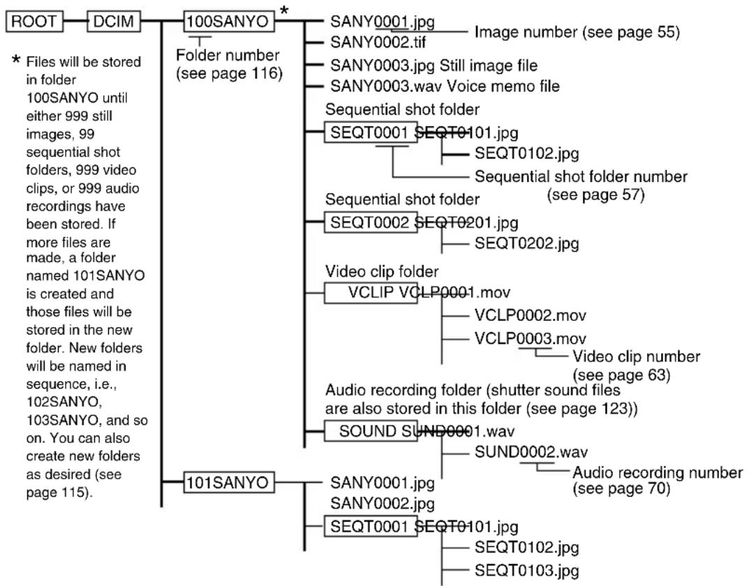
flowchart
graph TD
    A["ROOT"] --> B["DCIM"]
    B --> C["100SANYO"]
    C --> D["SANY0001.jpg"]
    C --> E["SANY0002.tif"]
    C --> F["SANY0003.jpg Still image file"]
    C --> G["SANY0003.wav Voice memo file"]
    C --> H["Sequential shot folder"]
    C --> I["SEQT0001 SEQT0101.jpg"]
    C --> J["Sequential shot folder (see page 57)"]
    C --> K["SEQT0002 SEQT0201.jpg"]
    C --> L["Video clip folder"]
    L --> M["VCLIP VCLP0001.mov"]
    L --> N["VCLP0002.mov"]
    L --> O["VCLP0003.mov"]
    C --> P["Audio recording folder (shutter sound files are also stored in this folder (see page 123))"]
    C --> Q["SOUND SUND0001.wav"]
    C --> R["SUND0002.wav"]
    C --> S["Audio recording number (see page 70)"]
    C --> T["SEQT0001 SEQT0101.jpg"]
    C --> U["SEQT0102.jpg"]
    C --> V["SEQT0103.jpg"]
    A --> W["* Files will be stored in folder 100SANYO until either 999 still images, 99 sequential shot folders, 999 video clips, or 999 audio recordings have been stored. If more files are made, a folder named 101SANYO is created and those files will be stored in the new folder. New folders will be named in sequence, i.e., 102SANYO, 103SANYO, and so on. You can also create new folders as desired (see page 115)."]
In addition to that shown above, other system files will also be created.
HELP
Do not modify the folders and file names in the disk using your computer
- Your digital disk camera stores and accesses data according to the rules given in the configuration shown above. If the folders, file names, or their configuration is modified by accessing the disk in some manner with your computer, your digital disk camera may not be able to playback data and may not operate properly.
Concerning the video clip data saved by the digital disk camera
- You can use QuickTime Ver. 3.0 or greater from Apple to playback the video clips. QuickTime 4.1 Pro for Windows and Macintosh is supplied with the SANYO Software Pack (supplied).
- To view images using MediaPlayer on a computer running Windows, use the software included in the SANYO Software Pack (supplied) to change the images to the Windows-compatible AVI format.
Erasing data
With your digital disk camera, if you ever make a mistake when capturing an image, filming a video clip, or recording an audio recording, or if it does not turn out as you want, or if you simply no longer need it, you can erase it. There are three methods of erasing data.
- Erasing a folder and all of its contents.
- Erasing a group of files (for sequential shots, this will erase the folder for one complete sequential shot).
- Erasing files one at a time.
With still images that have a voice memo attached, you can erase only the voice memo or erase the image and voice memo together.
Preparation
- Set the CAMERA/PLAY switch to "PLAY."
- Turn the mode selector dial to the playback mode of the type of file to be erased.
1 Display the file that you want to erase.
- For images and video clips, perform the procedure given in "Playing back still images" on page 52, "Playing back sequential shots" on page 57, or "Playing back video clips" on page 63 depending on the file type, and then proceed to step 2.
- For audio recordings, perform step 1 to 6 of "Playing back audio recordings" on page 69 and then proceed to step 3.
2 Press the MODE button.
● The Playback Setting Screen appears.
3 Press ▲ or ▼ on the arrow button to select the erase icon 📊 and press the SET button.
● The Erase Method Selection Screen appears.
4 Press ▲ on the arrow button to select the erase method.
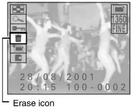
Ex. Still Image Playback Setting Screen

Ex. Erase Method Selection Screen for still images
■ For erasing still images (including those with voice memos attached)
FOLDER ERASE: Erases the current folder and all of its contents. All still images, sequential shots, video clips, and audio recordings inside the folder will be erased.
GROUP ERASE: Erases all the still images inside the current folder. Sequential shots, video clips, and audio recording will not be erased. Files inside other folders will not be erased.
ONE ERASE: Erases the still image currently being displayed.
EXIT: Returns you to the Playback Setting Screen.
■ For erasing sequential shots
FOLDER ERASE: Erases the current folder and all of its contents. All still images, sequential shots, video clips, and audio recordings inside the folder will be erased.
GROUP ERASE: Erases all the images inside the current sequential shot folder. Other sequential shots folders inside the current folder will not be erased. Still images, video clips, and audio recording will not be erased. Files inside other folders will not be erased.
ONE ERASE: Erases the image currently being displayed.
EXIT: Returns you to the Playback Setting Screen.
■ For erasing video clips
FOLDER ERASE: Erases the current folder and all of its contents. All still images, sequential shots, video clips, and audio recordings inside the folder will be erased.
GROUP ERASE: Erases all the video clips inside the current folder. Still images, sequential shots, and audio recording will not be erased. Files inside other folders will not be erased.
ONE ERASE: Erases the video clip currently being displayed.
EXIT: Returns you to the Playback Setting Screen.
■ For erasing audio recordings
GROUP: Erases all the audio recordings inside the current folder. Still images, sequential shots, and video clips will not be erased. Files inside other folders will not be erased.
ONE: Erases the audio recording currently selected.
EXIT: Returns you to the Playback Setting Screen.
5 Press the SET button.
● The Erase Confirmation Screen appears.
- For still images with a voice memo attached, a screen allowing you to select whether to erase just the voice memo or erase the still image and the voice memo will appear. See “Erasing still images with a voice memo attached” on page 151.
- If you select "ONE" for erasing audio recordings, only the audio recording selected will be erased. If you selected "GROUP," "ERASE GROUP?" appears.
- If you selected anything other than "FOLDER ERASE," proceed to step 6.

Ex. Erase Confirmation Screen for one still image
- If you selected "FOLDER ERASE," the Folder Erase All Confirmation Screen appears showing you whether or not the folder contains still image (including sequential shots), video clips, and audio recordings.
O: There are files present
- : There are no files present
- To erase these files, select "ERASE" and press the SET button. "ERASING" appears and the folder and all of its contents are erased.
ERASE: To erase the folder and all of its contents EXIT: To cancel the procedure and return to the Erase Method Selection Screen

Folder Erase All Confirmation Screen
6 Press ▲ on the arrow button to select “ERASE IMAGE,” “ERASE CLIP,” “GROUP ERASE,” or “ERASE” and press the SET button.
- If you selected "GROUP" for audio recordings, select "YES" and press the SET button.
- "ERASING" appears and the selected files are erased.
- If files that are protected are selected, "PROTECTED" appears and you return to the Erase Confirmation Screen. Protected files cannot be erased. To erase protected files, first remove the protection (see page 152).
- If all the files have been erased, "NO FILE" appears (see page 34).
NOTE
If some files cannot be erased
- Even if you select "GROUP ERASE," files that are protected cannot be erased. To erase protected files, first remove the protection (see page 152).
Erasing still images with a voice memo attached
- After pressing the SET button at step 5 on page 150, the Still Image With Voice Memo Erase Screen appears for you to select whether you want to erase only the voice memo or the voice memo and the still image.
① Press ▲ to select what is erased.
SOUND ONLY: To erase only the voice memo
IMAGE+SOUND: To erase the voice memo and the still image
② Press the SET button.
● The select data is erased.
If the erasing takes a long time
- If you selected "FOLDER ERASE" and there is a large amount of data in the folder (i.e., many sequential shots or images), it may take a long time for the data to be erased. Wait until the erase is completed.
Be aware of temporary data for video clip interval shooting (see page 106) or for animation shooting (see page 111)
- This temporary data is not considered a video clip and therefore does not show up in the Folder Erase All Confirmation Screen. This data also does not show up in the Folder Information Screen (see page 118). Be aware of this when erasing all the data in a folder or formatting a disk.
Protecting files from being erased
Your digital disk camera allows you to protect important files that you do not want to erase or do not want to have erased by mistake.
Preparation
- Set the CAMERA/PLAY switch to "PLAY."
- Turn the mode selector dial to the playback mode of the type of file to be protected.
1 Display the file that you want to protect.
- For images and video clips, perform the procedure given in "Playing back still images" on page 52, "Playing back sequential shots" on page 57, or "Playing back video clips" on page 63 depending on the file type, and then proceed to step 2.
- For audio recordings, perform step 1 to 6 of "Playing back audio recordings" on page 69 and then proceed to step 3.

Ex. Still Image Playback Setting Screen
2 Press the MODE button.
● The Playback Setting Screen appears.
3 Press ▲ or ▼ on the arrow button to select the protect icon ☐ and press the SET button.
- "LOCKED" appears and then you return to the Playback Setting Screen.
● The selected file is protected. - For files that are protected, the protect mark 🔒 appears.
- To protect another file, press ◀ or ▶, or turn the control dial, and select the next file. Then perform step 3 above.
- To exit the Playback Setting Screen, press the MODE button.
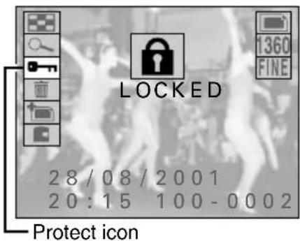
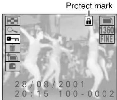
NOTE
- Even protected files will be erased if the disk is reformatted (see page 157).
To remove the protection from a file
- Display the desired file and perform steps 2 and 3 above. The protect mark will disappear and the protection removed.
Copying or moving files
Your digital disk camera allows you to move files from one folder to another folder or make another copy of a file into the same folder.
Preparation
- Set the CAMERA/PLAY switch to "PLAY."
- Turn the mode selector dial to the playback mode of the type of file to be copied or moved.
1 Display the file that you want to copy or move.
- Perform the procedure given in "Playing back still images" on page 52, "Playing back sequential shots" on page 57, or "Playing back video clips" on page 63 depending on the file type.
2 Press the MODE button.
● The Playback Setting Screen appears.
3 Press ▲ or ▼ on the arrow button to select the copy/move icon ☐ and press the SET button.
● The Copy/Move Selection Screen appears.
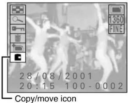
Ex. Still Image Playback Setting Screen
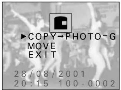
Copy/Move Selection Screen
4 Press ▼ on the arrow button to select the desired function.
COPY → PHOTO-G: To copy and save the displayed image as a still image
MOVE: To move the displayed image to a different folder
EXIT: To return to the Playback Setting Screen
5
Press the SET button.
- If you selected "COPY → PHOTO-G," the displayed image is copied and saved as a still image.
- If you selected "MOVE," the Destination Folder Selection Screen appears. Proceed to step 6 and select the destination folder for the move.

Destination Folder Selection Screen
6
Press ▲ or ▼ on the arrow button to select the destination folder and press the SET button.
● The displayed image is moved to the selected folder.
- If a sequential shot is displayed, the complete sequential shot folder is moved.

NOTE
What happens to the file or folder number after it is moved?
Still images and video clips: The file number becomes the number after the last number in the folder.
Sequential shots: The sequential shot folder number becomes the number after the last sequential shot folder number in the folder.
HELP
If "PROTECTED" appears and the move cannot be performed
- Files that are protected cannot be moved. To move the file, first remove the protection (see page 152).
FORMATTING THE DISK
About the iD PHOTO disk
The iD PHOTO disk that is inserted into your digital disk camera is a magneto-optic cartridge with a storage capacity of 730 megabytes. Be sure to insert the iD PHOTO disk into the digital disk camera before using the digital disk camera. In this manual the iD PHOTO disk is referred to as "disk" for brevity.
Preventing data from being erased
- By moving the write-protect tab to the key (O _T ) mark on the disk, you can prevent data from being written to the disk, prevent data from being erased from the disk, and prevent the disk from being reformatted. Move the write-protect tab back to its original position to allow data to be written, data to be erased, and the disk to be reformatted.
- You can move the write-protect tab with a ballpoint pen or other similar pointed tool.
Part names
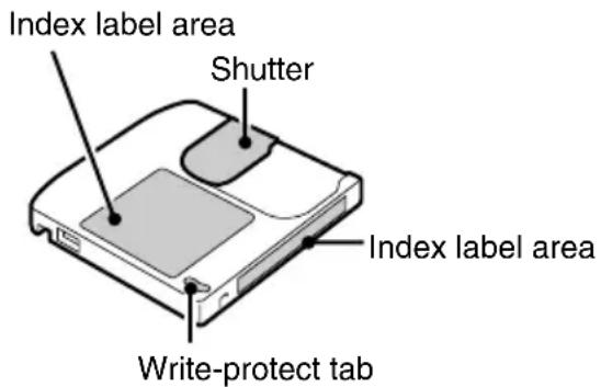
| Write protected | Write enabled |
 | 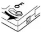 |
If "REFORMAT?" appears
The disk has not yet been formatted, so to be able to use the disk with your digital disk camera, you will need to first format it with the digital disk camera. If an unformatted disk or disk whose formatting has become corrupt is inserted into the digital disk camera, regardless of the position of the mode selector dial, "REFORMAT?" will appear (see page 156) and the disk mark and "----" will appear flashing in the mode display panel. If this occurs, perform the operations given below.
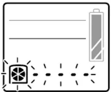
natural_image
Simple line drawing of a battery and a fan with dashed lines indicating alignment or alignment (no text or symbols)Mode display panel
Important
Be aware that if the disk is reformatted, all the data currently stored on the disk will be erased.
1 Press ▲ on the arrow button to select "YES."
- There are two types of format screens. Both are shown to the right.
- If the Quick Format Screen with the quick format icon 📄 appears, select "NO" and press the SET button to display a screen that allows you to select the full format process. At this screen, select "FULL FORMAT" and press the SET button.
- If the Full Format Screen with the full format icon 📄 appears, connect the supplied AC adapter/charger (see page 29). If the AC adapter/charger is not connected, you cannot reformat the disk.

Quick Format Screen
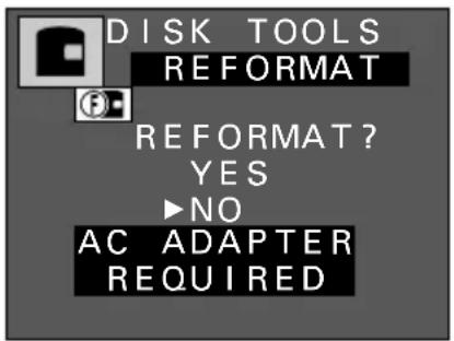
Full Format Screen
2 Press the SET button.
- Formatting starts.
- During formatting, "FORMATTING" appears.
- Do not turn off the digital disk camera while it is formatting a disk.
● A full format requires approximately 20 minutes. - To cancel formatting, press the MODE button. (To cancel the full formatting process, press the MODE button after the status bar appears.) If you cancel the format, be sure to properly format the disk later.
- When "FORMATTING" disappears and you return to the normal operation screen, formatting has been completed successfully.
- If formatting cannot be completed properly for a disk, the disk may be damaged. Replace the disk with a new one.
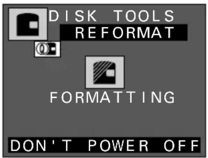
Quick Format Processing Screen
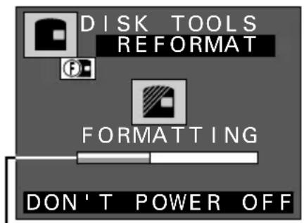
— Indicator of format process Full Format Processing Screen
HELP
If "PROTECTED" appears
- The write-protect tab on the disk is set to the key (O-n) mark. To format the disk, the write-protect tab must be set to the write-enabled position.
NOTE
- A newly purchased disk may display the Quick Format Screen or the Full Format Screen depending on how they were formatted before packaging. This is not a malfunction.
Reformatting a disk
When a disk is used for the first time, “REFORMAT?” appears (see page 156) and you automatically start the formatting process. However, depending on the condition of the disk, this message may not appear. To format the disk in such a case, follow the procedure given below.
Also, even for disks that have been formatted with the digital disk camera before, data may become corrupt or the disk may become reformatted by a computer making the disk unusable with the digital disk camera. If this happens, formatting the disk with the digital disk camera may make the disk usable again.
There are two types of formatting available with your digital disk camera.
Quick format: For quickly erasing all the data on the disk.
Full format: Before capturing important images, to ensure that images are captured properly, it is recommended to perform a full format beforehand.
Important
Be aware that if the disk is reformatted, all the data currently stored on the disk, even protect data (see page 152), will be erased.
Preparation
- Insert a disk with its write-protect tab set to the write-enabled position (see page 155).
- Turn the mode selector dial to 📋 to display the Option Screen.
1 Press the arrow button to select the disk icon ☐ and press the SET button.
● The Disk Tools Screen appears.
2 Press ▼ on the arrow button to select the quick format icon Ⓗ or the full format icon Ⓕ.
- When selecting the full format, be sure to connect the digital disk camera to an AC power outlet with the supplied AC adapter/charger. The full format takes approximately 20 minutes. If the AC adapter/charger is not connected, “AC ADAPTER REQUIRED” appears flashing and the format cannot be performed.
For the quick format: Select 🔊
For the full format: Select
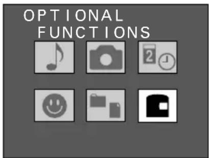
Option Screen
Quick format icon
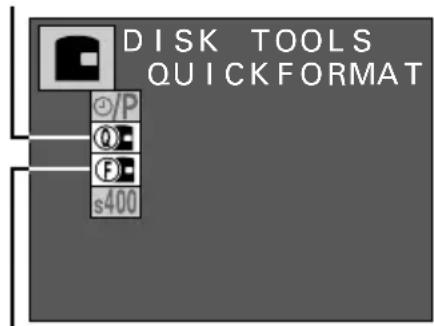
Full format icon
Disk Tools Screen
3 Press the SET button.
● The Format Confirmation Screen appears.

Format Confirmation Screen when the quick format icon 🔒 was selected

Format Confirmation Screen when the full format icon 📄 was selected
4 Press ▲ on the arrow button to select "YES" and press the SET button.
- Formatting starts.
- During formatting, "FORMATTING" appears.
- Do not turn off the digital disk camera while it is formatting a disk.
● A full format requires approximately 20 minutes. - To cancel formatting, press the MODE button. (To cancel the full formatting process, press the MODE button after the status bar appears.) If you cancel the format, be sure to properly format the disk later.
- When formatting is completed, you return to the Disk Tools Screen.
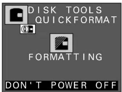
Format Processing Screen when the quick format icon Ⓞ was selected
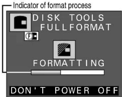
Format Processing Screen when the full format icon Ⓕ was selected
HELP
If "FORMAT FAILED" and ✕ appear
- Format was not completed properly. Press the SET button and try again.
USING WITH A COMPUTER SYSTEM
By connecting your digital disk camera to a computer, you can greatly expand the uses available with your digital disk camera.
Connecting to your computer
Your digital disk camera is equipped with a USB terminal and an IEEE1394 terminal for connecting the digital disk camera to a computer. By installing the software included in the SANYO Software Pack, you can download and edit files saved in your digital disk camera, operate your digital disk camera from your computer, and much more. (For using the different interfaces, the driver software for the interface is required.)
Connecting to the USB terminal

flowchart
graph LR
    A["Computer"] --> B["To USB port To USB terminal"]
    B --> C["USB computer interface cable (supplied)"]
    D["Mode selector dial"] --> E["Device with cable"]
    E --> F["Interface cover"]
- By connecting to a computer using the USB terminal, you can use the software included in the SANYO Software Pack to download data from the disk in the digital disk camera to the computer and operate the digital disk camera remotely from the computer.
- When the mode selector dial is set to and the USB connection is made, "PC--U" appears in the mode display panel.

Display when USB connection is made
NOTE
- When the digital disk camera is connected to a computer, the monitor of the digital disk camera turns off and all control except for the power button and mode selector dial become inoperable.
Connecting to the IEEE1394 terminal

flowchart
graph TD
    A["Computer"] --> B["Interface cover"]
    B --> C["Mode selector dial"]
    C --> D["To IEEE1394 port To IEEE1394 terminal"]
    D --> E["IEEE1394 computer interface cable (supplied)"]
- By connecting to a computer using the IEEE1394 terminal, you can use the iD PHOTO disk drive of the digital disk camera as an external drive of your computer. Then you can handle the data stored in the disk from your computer.
- When the mode selector dial is set to and the IEEE1394 connection is made, "PC--F" appears in the mode display panel.

Display when IEEE1394 connection is made
Selecting the IEEE1394 baud rate
Your digital disk camera supports communication up to 400 Mbps, but depending on the computer to which the digital disk camera is connected, the communication may become unstable. If this is the case, select the s200 icon in the baud rate menu to restore stable communication.
① Turn the mode selector dial to ↗ to display the Option Screen.
② Press the arrow button to select the disk icon ☐ and press the SET button.
● The Disk Tools Screen appears.
③ Press ▼ to select the baud rate menu.
4 Press ▶ to select the desired baud rate.
s200: Sets the baud rate to a maximum of 200 Mbps
s400: Sets the baud rate to a maximum of 400 Mbps
⑤ Press the SET button.
- The new baud rate is set.

Baud rate menu Disk Tools Screen
About the accessories available for your digital disk camera
The accessories available for your digital disk camera are given below.
●Li-ion battery pack (part number: UR-121AEX, UR-121A)
One Li-ion battery pack UR-121.
- iD PHOTO disk (part number: DSM-D730ACEX, DSM-D730ACU)
One 730-megabyte iD PHOTO disk DSM-D730A.
TROUBLESHOOTING
| Problem Cause | Action | Reference page | |||
| Power Does not turn on. | Battery pack is not installed. | Properly install battery pack. | 27 | ||
| Battery pack is not properly installed. | |||||
| Battery pack is dead. Recharge battery pack or replaced with a charged one. | 24, 27 | ||||
| Power cord is not plugged into wall outlet (when using AC adapter/charger). | Properly plug it in. | 29 | |||
| Power cord is not plugged into power socket (when using AC adapter/charger) | |||||
| Disk is not inserted. Properly insert disk. 30 | |||||
| Due to cold temperatures, battery pack temporarily lost power. | Place battery pack in pocket to warm it up before using. | 39 | |||
| Shooting Shutter release button does not work. | Power is not turned on. If power save function has activated, press shutter release button or power button once and then perform shooting. | 35 | |||
| Clock icon appears (ready status). | Wait until clock icon disappears. | 51 | |||
| Disk is full ("DISK FULL" appears in monitor and "REMAIN 0" appears in mode display panel). | Replace with a new disk. | 30, 31 | |||
| Erase unnecessary files or save files to another disk and then erase them. | 147, 149 | ||||
| Flash does not light. | Flash is not extended out. | Press flash pop-up button to stand up flash. | |||
| Subject is bright and flash is judged unnecessary by digital disk camera. | Not a malfunction. | ||||
| Battery pack is low. Recharge battery pack or replaced with a charged one. | 24, 27Reference page | ||||
| Problem Cause Action | |||||
| LCD monitor and viewfinder | When used in cold weather, image seems to leave traces as it moves. | Effects of the liquid crystals. | Not a malfunction. Such spots that appear in the monitor only appear in the monitor and will not be recorded with images. | ||
| Images displayed contain some red, blue, and green dots, or there are black spots visible. | |||||
| Area around LCD monitor is warm. | Normal effect due to internal structure. | Not a malfunction. | |||
| No image appears during shooting. | Lens cap is attached. Remove lens cap. | 18 | |||
| No playback image appears. | CAMERA/PLAY switch is set to “CAMERA.” | Turn CAMERA/PLAY switch to “PLAY.” | 46 | ||
| Viewing images | Focus does not work. | Subject is too close. If subject is between 3 to 60 cm away, set focus to (macro focus) or (total range focus); if subject is farther than 60 cm away, set focus to (normal focus) or (total range focus) | 72, 90 | ||
| Focus is not set properly. | |||||
| Digital disk camera moved when shutter release button was pressed. | Hold digital disk camera correctly and slowly press shutter release button halfway to lock focus. Then press shutter release button fully down. | 49, 51 | |||
| Focus does not lock. | |||||
| Shutter speed is too slow. | When capturing images with slow shutter speed, use tripod to stabilize digital disk camera and press shutter release button with remote control. | 95 | |||
| Lens is dirty. Clean lens. | 14 | ||||
| Viewing images | Image is too dark. | Flash was blocked by finger or other object. | Hold digital disk camera correctly and make sure flash is not obstructed. | 49 | |
| Subject was too far away. | Capture images inside flash range (within 2.8 meters). | 75 | |||
| Subject was lit from behind. | Use forced flash mode. | 76 | |||
| Use exposure correction. | 87 | ||||
| Capture using spot sample AE setting. | 93 | ||||
| Not enough light. Use exposure setting. | posure control setting. | 92 | |||
| Use ISO sensitivity setting. | 114 | ||||
| Image is too bright. | Forced flash is being used. | Set to flash mode other than forced flash. | 76 | ||
| Subject is too bright. Change camera angle or use other means to decrease subject brightness. | |||||
| Use exposure correction. | 87 | ||||
| Capture using spot sample AE setting. | 93 | ||||
| Shutter speed is slower than proper value (for shutter speed priority AE). | Adjust shutter speed to proper value. | 94 | |||
| ISO sensitivity is not set correctly. | Set ISO sensitivity to proper value. | 114 | |||
| Color for images captured indoors are not correct. | Due to ambient lighting. | Capture image using forced flash mode. | 76 | ||
| White balance is not set correctly. | Set white balance correctly. | 96 | |||
| Video clip image flickers. | Video clip was filmed under fluorescent lighting. | Set shutter speed to 1/100. | 94 | ||
| Viewing images | Part of image is missing. | Lens was blocked by shoulder strap, finger, or other object. | Hold digital disk camera correctly and make sure lens is not obstructed. | 49 | |
| No image appears (2 appears). | Playing back images on disks from other digital cameras may cause malfunctions. | Play back images on disks from your digital disk camera. | 54 | ||
| Audio recordings | No sound. Volume | setting is too low. | Adjust volume. | 70 | |
| Video clip was shot using interval shooting or animation shooting. | Sound is not recorded for interval shooting or animation shooting. | 98, 107 | |||
| Sound is noisy. Disk drive or lens movements are recorded (due to digital disk camera structure). | Not a malfunction. To prevent operations from being recorded, use supplied external microphone. | 49, 61, 68, 79 | |||
| Connecting to television. | No sound or image. | Digital disk camera is not properly connected to television (AV cable is connected to MIC input, etc.). | Connect properly (connect AV cable to AV output terminal on digital disk camera). | 71 | |
| Television input is not set correctly. | Set input to “VIDEO.” | ||||
| No sound. Volume | of television is too low. | Adjust volume. | |||
| Miscellaneous | Digital disk camera will not operate. | Possible temporary internal circuitry problem. | 1Press EJECT lever and remove disk. 2Insert disk again. 3Turn power on. Or remove both battery pack and clock backup battery, wait a few moments, and then reinstall them. (If using AC adapter/charger, disconnect DC plug from digital disk camera.) | ||
| “SYSTEM ERROR” is displayed. | |||||
| Digital disk camera settings are lost.Problem Cause | Clock backup battery is dead so settings are not backed up.Action | Replace clock backup battery with new one. | 23Reference page | ||
| Miscellaneous | Digital disk camera does not operate immediately after being turned on. | Normal effect due to internal structure. | When power is turned on, disk contents are read. While disk is read, disk mark appears rotating and digital disk camera cannot be operated. Wait until disk mark stops rotating. | 30 | |
| Sounds can be heard during power save mode. | Sounds from internal circuitry. | Not a malfunction. | 35 | ||
| Remote control does not work. | Remote control codes do not match. | Set remote control codes properly. | 38 | ||
| Remote control mode is set to [IMAGE]. | Set remote control mode to [IMAGE]. | 124 | |||
Dust is inside viewfinder. 1Remove screws | (2)on side of viewfinder.2Pull out and remove eyecup.3Clean dust from inside eyecup and viewfinder with a blower or soft cloth.●Be careful not to allow dust to get inside digital disk camera.4Put eyecup back to original position and secure with screws (2). | 14 | |||
Error messages
Error messages will appear in the monitor or mode display panel in response to conditions of the digital disk camera or disk.
| Monitor display Mode display panel Meaning and remedy | ||
| Monitor does not light |  | Disk is not inserted.↓Insert disk (see page 30). |
| REFORMAT?YES▶NO |  | Disk is not formatted, or formatting is corrupt.↓Follow instructions on screen and format disk (see page 155). |
 | 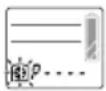 | Disk is write-protected.↓Set disk to write-enabled (see page 155). |
 | 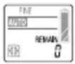 | Disk is full.↓Replace with disk that is not full (see pages 30, 31).Erase unnecessary files (see page 149).Save files to other media and erase from disk (see page 159). |
 | 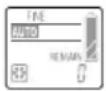 | Disk is not recognized.↓Remove disk and insert again.● If “REFORMAT?” appears, follow instructions on screen and reformat disk (see page 157).● If “????” appears again, either replace disk or press the SET button.●Leaving the digital disk camera turned on for a few minutes may remedy the problem. |
 or or  |   | Battery pack is dead.↓Replace with charged battery pack or use AC adapter/charger (see pages 24, 29, 40). |
| [XC34] appears in upper right | Normal display | Digital disk camera becomes warm (see pages 17, 62).↓Can still be used, but turn off power as soon as possible. |
| [70x5]HIGH TEMPTOK | 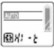 | Digital disk camera has become hot (see pages 17, 62).↓Press SET button and wait for “HIGH TEMP” to disappear before resuming use. (Temperature has risen beyond allowable range so turn off as soon as possible.)If temperature is still high, “HIGH TEMP” will appear again. (Only power button will operate.)Turn off digital disk camera to quickly lower temperature. |
| CREATENEW FOLDER101▶OK | Normal display | No more files can be saved to current folder so new folder is created.↓Press SET button. |
 FILES MAYBE LOSTDISK:READ ONLY▶OK FILES MAYBE LOSTDISK:READ ONLY▶OK | 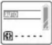 | Problem with disk.↓Press SET button. Some files on the disk may be lost (including files recorded by digital disk camera). Disk is made to read-only disk for reading non-corrupt files.Save files from disk to computer and full format disk with digital disk camera (see page 157) to return disk to normal.If “DISK ERROR” appears during full format, replace disk with new one. |
| FILE RECOVERYPOWER DOWNWHILE RECORDINGTRY RECOVER▶OK | Normal display | Power was turned off during filming of video clip.↓Press SET button.“SEARCHING” appears and video clip is repaired.On rare occasions, the video clip may not be able to be repaired. |
SPECIFICATIONS
Digital disk camera
| Type CCD digital camera (recording and playback) | ||
| Recording system Digital recording | ||
| Format standards iD format standards | ||
| Recording image file format Still images: JPEG format, TIFF (non-compressed YCbCr) format (Exif Ver. 2.1 compliant)Video clips: QuickTime MovieAudio: wav (monaural) | ||
| Recording media | iD PHOTO magneto-optic disk (CAD magnetic super resolution) (730 MB when unformatted) | |
| Imaging element 1/2-inch CCD solid-state type image pickup, 1,500,000 pixels(image elements), progressive scan, primary color filter | ||
| Recording resolution 1,360 x 1,024 pixels (still images and sequential shots only)1,024 x 768 pixels (still images and sequential shots only)640 x 480 pixels (still images, sequential shots, and video clips)320 x 240 pixels (video clips only)160 x 120 pixels (video clips only) | ||
| Video clip frame rate 640 x 480 pixels: 30 fps/15 fps320 x 240 pixels: 30 fps/15 fps160 x 120 pixels: 30 fps/15 fps | ||
| Data compression TIFF (non-compressed YCbCr) (for still images only)FINE (low compression) (for still images andNORM (moderate compression) sequential shots only) | ||
| White balance Full-auto TTL, manual setting possible | ||
| Lens Optical 3x zoom | lens with built-in ND filter | f = 7 to 21 mm (equivalent to f = 38 to 114 mm for 35-mm film camera)autofocus, 7 groups, 8 elements, aspheric lens (2) |
| Filter diameter 52 mm | ||
| Aperture | Open F2.4 (wide) to F4.4 (tele), smallest F8 (wide) to F12.9 (tele) | |
| ND filter | ND - 0.6 (25.1% transmittance)(covers F8.0)Effective smallest aperture value F = 16.0 (wide) to 25.8 (tele) | |
| Exposure metering | Matrix metering/center-weighted metering | |
| Exposure control type | Program AE for variable aperture and shutter range/AE lock/spot sample AE/shutter speed priority AE/aperture priority AE/manual exposure controlExposure control functions available at shooting screen (0±1.5 EV in 0.5-EV steps) | |
| Range | 60 cm to infinity (normal focus), 20 cm (min. 3 cm) to 60 cm (macro focus), 20 cm (min. 3 cm) to infinity (total range focus) | |
| Digital zoom For shooting: Still image and sequential shot mode(resolution 640): 1x to 2.1xVideo clip (resolution 320): 1x to 2xVideo clip (resolution 160): 1x to 4xFor playback: 1.0x to 21x (varies with resolution) | |||
| Shutter Still image shooting mode:16 to 1/500 sec (Slow shutter: 16, 8, 4, 2, 1 sec)Sequential shot shooting mode:1/30 to 1/2,000 sec (resolution 640)1/15 to 1/2,000 sec (resolution 1360 or 1024)Video clip shooting mode:1/30 to 1/2,000 sec (frame rate 30f)1/15 to 1/2,000 sec (frame rate 15f) | |||
| Sensitivity Auto (equivalent to ISO 100 to 200), and equivalent to ISO 100,ISO 200, and ISO 400 (set at Manual Shooting Screen) | |||
| Viewfinder 0.55-inch digital viewfinder (with diopter adjustment) | |||
| LCD monitor 1.8-inch low-temperature polysilicon TFT color liquid crystal | |||
| LCD monitor pixels Approx. 110,000 pixels | |||
| Flash working range 0.6 to 2.8 m (normal focus, lens wide), 0.6 to 1.5 m (normal focus, lens tele), 0.2 to 0.6 m (macro focus), guide number: 6.8 | |||
| Flash modes Automatic flash mode, forced flash mode (slow synchronic shooting possible), red-eye reduction flash mode, flash off mode | |||
| Focus TTL-type AF (TTL contrast detection method), manual focus, fixed focus | |||
| Self-timer 10-second delay (initial setting), can be set up to 9 hours 59 minutes 59 seconds | |||
| Special shooting functions Interval shooting (still image and video clip)Animation shooting (video clip) | |||
| Time/date Recorded with image data (automatic calendar from 1970 to 2039), clock has exclusive backup battery (CR2025) | |||
| Ambient environment | Temperature | 0 to 35°C (operation), -20 to 60°C (storage) | |
| Humidity | 30 to 90% (operating, no condensation),10 to 90% (storage, no condensation) | ||
| Power supply | Battery | Li-ion battery pack (UR-121) x 1Clock backup battery (CR2025) x 1 | |
| AC adapter/charger (supplied) | NC-LSC04WSA | ||
| Dimensions | 93 (W) x 140 (D) x 89 (H) mm | ||
| Weight | Approx. 575 g (without battery pack, disk, grip belt, and shoulder strap) | ||
Connectors
| AV output terminal 3.5-mm mini jack | ||
| MIC input terminal 3.5-mm mini jack, 2 kΩ, monauralSensitivity: -42 dB max., plug-in power | ||
| DC IN terminal DC 9.2 V (for use with supplied AC adapter/charger NC-LSC04WSA only) | ||
| USB terminal USB port, supports cam control mode | ||
| IEEE1394 terminal IEEE1394 | port (4P), supports disk drive mode | |
Battery operation
| Shooting Approx. 1 hour 30 minutes | |
| Playback Approx. 2 hours | |
- Until batteries run out when using the supplied disk and the supplied Li-ion battery pack at full charge at a 20°C ambient temperature.
- The time of operation may vary depending on the conditions of the battery pack and the conditions of use. Especially when used at temperatures below 10^ , the battery operation time is drastically reduced.
Possible number of images/possible shooting time/possible recording time
The table below shows the approximate possible number of images, the possible shooting time, and the possible recording time that can be stored on the supplied iD PHOTO disk.
| Shooting recording mode | Resolution setting | Compression ratio setting | Frame rate setting | Approximate maximum number of images or amount of recording time |
| Still image mode (no voice memo) | 1360 | TIFF | - 255 images | |
| FINE | - 1200 images | |||
| NORM | - 2000 images | |||
| 1024 | TIFF | - 450 images | ||
| FINE | - 2000 images | |||
| NORM | - 3000 images | |||
| 640 | TIFF | - 1150 images | ||
| FINE | - 4800 images | |||
| NORM | - 12000 images | |||
| Still image mode (with voice memo) | 1360 | TIFF | - 250 images | |
| FINE | - 1100 images | |||
| NORM | - 1600 images | |||
| 1024 | TIFF | - 425 images | ||
| FINE | - 1600 images | |||
| NORM - 2300 images | ||||
| 640 | TIFF | - 1000 images | ||
| FINE | - 3000 images | |||
| NORM | - 5000 images | |||
| Sequential shot mode | 1360 | FINE | - 1200 images | |
| NORM | - 2000 images | |||
| 1024 | FINE | - 2000 images | ||
| NORM | - 3000 images | |||
| 640 | FINE | - 4800 images | ||
| NORM | - 12000 images | |||
| Video clip mode | 640 | - | 30f | 8 minutes |
| - | 15f | 16 minutes | ||
| 320 | - | 30f | 20 minutes | |
| - | 15f | 40 minutes | ||
| 160 | - | 30f | 60 minutes | |
| - | 15f | 120 minutes | ||
| Audio recording - | - | - | 2 hours x 12 | |
- Even with disks of the same capacity, the amount of data that can actually be stored may differ depending on conditions during shooting or recording.
Approximate maximum number of sequential shot images that can be captured when shutter release button is pressed once
The number of images captured with a sequential shot will differ depending on the image quality as shown in the table below.
| Resolution setting Compression ratio setting Normal sequential shot AE shift sequential shot | |||
| 1360 | FINE | 11 images | 7 images |
| NORM | 20 images | ||
| 1024 | FINE | ||
| NORM | 30 images | ||
| 640 | FINE | 40 images | |
| NORM | |||
Internal disk drive
| Supported media iD PHOTO | disk 730 MB |
| Recording format Magneto optical recording formatMagnetic super resolution technology (CAD-MSR)Laser pulse magnetic field modulation recording | |
| Direct overwrite Supported | |
| Pickup Laser wavelength: 658 | nm, objective lens of NA 0.62 |
Supplied iD PHOTO disk
| Part number DSM-D730A (conforms to iD PHOTO standards) | |
| Recording capacity 730 MB (unformatted) | |
| Direct overwrite Supported | |
| File system UDF (universal disk format) Ver. 1.5 | |
| Dimensions 59.5 (W) x 56.5 (D) x 4.8 (H) mm | |
| Weight Approx. 13 g (without protective case) | |
Supplied AC adapter/charger
| Part number NC-LSC04WSA | ||
| Power supply AC 100 to 240 V (26 to 36 VA), 50 to 60 Hz | ||
| Rated output DC 8.4 V, 0 to 1.1 A (charging)DC 9.2 V, 0 to 1.2 A (DC output) | ||
| Compatible battery Supplied or sold separately Li-ion battery pack UR-121 | ||
| Ambient environment | Temperature | 0 to 35°C (operation), -20 to 60°C (storage) |
| Humidity 45 to | 85% (no condensation) | |
| Dimensions 55 (W) x 38.5 (H) | x 120 (D) mm | |
| Weight Approx. 190 g (without power cord) | ||
Supplied Li-ion battery pack
| Part number UR-121 | ||
| Voltage 7.4 V | ||
| Capacity | 1,600 mAh | |
| Ambient environment | Temperature | 0 to 40°C (operation and recharging), -20 to 30°C (storage) |
| Humidity 45 to | 85% (no condensation) | |
| Dimensions 37.6 (W) x 71.6 (D) x 20.4 (H) mm | ||
| Weight Approx. 95 g (without protective cover) | ||
- Sanyo Electric reserves the right to modify product designs and specifications without notice and without incurring any obligations.
http://www.idshot.com/en/
- iDshot
- Caution for laser
- Laser
- Warning
- FOR AMERICAN USERS
- Declaration of Conformity
- FOR CANADIAN USERS
- BEFORE READING THE MANUAL
- Regarding the data storage media
- Caution
- Symbols used in this manual
- CONTENTS
- Preparation
- Recording and playback
- Shooting functions
- Speciality shooting
- Camera settings
- Editing
- Disk operations
- Appendices
- USING YOUR DIGITAL DISK CAMERA SAFELY AND CORRECTLY
- SAFETY PRECAUTIONS
- LI-ION BATTERY PACK (UR-121)
- DANGER
- ■Cautions concerning the locations of use and storage
- ●Ambient temperature during use or charging: 0 to 40°C
- - Ambient temperature during storage: - 20 to 30° C
- ●Ambient humidity: 45 to 85% RH
- ■Only recharge using the supplied NC-LSC04WSA AC adapter/charger
- ■Only use with the specified devices
- ■Do not remove or damage the covering
- ■If you come in contact with electrolyte, immediately rinse with water
- ■Always insert orientated as indicated
- DIGITAL DISK CAMERA AND AC ADAPTER/CHARGER
- ■Do not use the digital disk camera or AC adapter/charger if it makes a strange noise, emits a strange odor, or if smoke comes out from it
- Digital disk camera
- AC adapter/charger
- ■Do not modify or open the cabinet
- ■Do not insert metal objects or the like
- ■Do not use while driving
- ■Be aware of your surroundings during use
- ■Do not get the devices wet
- ■Do not handle with wet hands
- ■Do not use during a storm
- ■Do not place on an unstable surface
- ■Do not look into the sun
- - Do not use the flash close to a person’s face
- ■Do not use where there is risk of explosion
- ■Keep out of the reach of children
- ■Only use the specified battery pack and AC adapter/charger
- ■Use only to recharge the Sanyo UR-121 Li-ion battery pack
- ■ Do not invert the polarity ((+) and (-)) of the battery pack
- ■Use the AC adapter/charger with a 100 to 240 V AC power supply
- ■Do not damage the power cord or DC cord of the AC adapter/charger
- ■Cautions concerning the power cord
- ■Unplug the power cord from the power outlet when charging is finished
- ■Do not pull on power cord to unplug it
- ■Cautions when plugging in the battery charger
- ■Cautions when carrying the digital disk camera
- ■Cautions during use and storage
- Operating environment
- ■Do not cover with a cover, rug, or similar object
- ■Be aware that internal temperatures rise during use
- ■Do not connect the AC adapter/charger to an electronic transformer
- ■Cautions if the digital disk camera or AC adapter/charger is not going to be used for a long period
- CONCERNING THE LITHIUM BATTERY CR2025
- ■Cautions concerning the battery CR2025
- INSTRUCTIONS FOR THE PROPER USE OF YOUR DIGITAL DISK CAMERA
- ■Cautions before capturing important images
- ■Cautions concerning copyrights
- ■Cautions when cleaning the digital disk camera and AC adapter/charger
- Cleaning procedure
- ■Cautions when cleaning the lens
- ■Cautions concerning the battery pack terminals
- ■Cautions when not using the digital disk camera
- When not using the digital disk camera for a long period
- ■Cautions concerning condensation
- Be careful of condensation under the following conditions
- If condensation seems likely to form
- ■Cautions concerning undesired interference
- When using the supplied microphone or IEEE1394 cable
- ■Cautions concerning magnetism
- ■ Cautions concerning the iD PHOTO disk
- Cautions when handling the iD PHOTO disk
- Cautions when carrying or storing the iD PHOTO disk
- Making sure that data on your iD PHOTO disk does not become erased
- Move the write-protect tab to the "O-m" mark.
- ■Cautions concerning data storage
- ■Cautions concerning vibrations
- ■Cautions concerning rises in temperature
- CHECKING THE INCLUDED ACCESSORIES
- PARTS NAMES
- Front
- Rear
- Bottom
- Remote control
- POWER SUPPLY
- Installing the clock backup battery
- 1
- Open the battery pack cover.
- 2
- Open the clock backup battery cover and install the clock backup battery.
- NOTE
- Saving the camera settings
- Charging the battery pack
- Remove the protective cover from the battery pack.
- Insert the battery pack into the AC adapter/charger.
- Insert the supplied power cord into the socket on the AC adapter/charger.
- Plug the power cord into a power outlet (AC 100 to 240 V).
- When the BATTERY CHARGE lamp turns off, unplug the power cord from the wall outlet.
- Remove the battery pack from the AC adapter/charger.
- If noise is received by a radio or television during charging
- Ambient temperature during charging
- Recharge the battery pack before use in the situations given below
- The BATTERY CHARGE and AC ADAPTER lamps
- HELP
- If the BATTERY CHARGE lamp does not turn off
- Installing the battery pack
- Open the battery pack cover.
- Attach the charged battery pack to the battery pack mating area.
- Close the battery pack cover.
- Removing the battery pack
- If the digital disk camera is turned on, turn it off (see page 35).
- Open the battery pack cover.
- Remove the battery pack.
- Close the battery pack cover.
- Using the AC power supply
- INSERTING AND EJECTING THE DISK
- Inserting the disk
- Push the EJECT lever in the direction of the arrow.
- Insert the disk into the disk holder.
- Push the disk holder closed.
- If the disk mark turns
- Ejecting the disk
- Be careful not to let the disk fall
- Push the EJECT lever in the direction of the arrow.
- Open the disk holder in the direction of the arrow.
- Gently pull out the disk.
- If the disk cannot be removed
- Turning on the digital disk camera
- Insert the disk (see page 30).
- Press the power button for more than one second.
- Changing the monitor
- To show the display in the viewfinder, move the monitor switch to "FINDER"
- To show the display in the LCD monitor, move the monitor switch to "MONITOR"
- If the timer mark (☐) in the mode display panel is flashing
- About the disk status display
- What to do if "NO FILE" appears
- Switch the playback mode
- Switch folders
- HINT
- Turning off the digital disk camera
- Press the power button for more than one second.
- Turning on the digital disk camera from the power save mode
- About the power save mode
- Turning the power back on
- Press the shutter release button or power button.
- SETTING UP AND USING THE REMOTE CONTROL
- Setting up the remote control
- Pull out the battery insulation sheet.
- Perform the remote control setting at the digital disk camera (see page 124).
- Using the remote control
- Replacing the remote control battery
- Pull out the battery holder.
- Remove the battery.
- Insert the new battery (CR2025).
- Push in the battery holder.
- Changing the remote control code
- Changing the remote control code from "1" to "2"
- Returning the remote control code to "1"
- CHECKING THE BATTERY PACK AND DISK
- Checking the battery pack
- Install the battery pack (see page 27).
- Turn on the digital disk camera (see page 32).
- If the LCD monitor goes off suddenly
- Checking the remaining disk space
- Display in mode display panel
- ●Remaining number of images/remaining recording time available
- ●Remaining percentage of disk space
- ●Remaining disk space
- SETTING THE DATE AND TIME
- Setting the clock
- Operation of buttons at the Date and Time Setting Screen
- Arrow button
- Other buttons
- Set whether or not to display the date and time at playback.
- Set the date format.
- 6
- Set the date and time (the clock setting).
- 7
- Press the SET button.
- Changing the date and time setting
- BASIC SHOOTING AND PLAYBACK OPERATIONS
- Setting the mode
- Switching between the shooting and playback modes
- Set the CAMERA/PLAY switch to "CAMERA" or "PLAY."
- Changing the mode
- Turn the mode selector dial to the icon of the desired mode.
- Attaching the grip belt and shoulder belt
- Proper use of your digital disk camera
- Using the supplied microphone
- Capturing and playing back still images
- Capturing still images
- Put the digital disk camera in the still image shooting mode.
- Select which monitor to use and compose the image.
- Using the viewfinder
- Using the LCD monitor
- 3
- Press the shutter release button.
- Playing back still images
- Put the digital disk camera in the still image playback mode.
- Press ◀ or ▶ on the arrow button to select the image you want to view.
- Using the control dial
- Useful playback features for still images
- Consecutive playback
- Press and hold ◀ or ▶ on the arrow button.
- Automatic playback (slide show)
- Press and hold ▲ or ▼ on the arrow button until "SLIDE SHOW" appears.
- To stop the automatic playback, press the arrow button.
- If "NO FILE" appears
- 9-image display playback
- Press the MODE button to display the Playback Setting Screen.
- Press the SET button.
- Press the arrow button to move the ✏ mark to the image you want to view and press the SET button.
- If ? appears in the 9-image display
- If an image number is missing
- Specific image number playback
- Press the F2 button.
- Turn the control dial to select the image number of the image that you want to view.
- Press the RETURN button.
- Capturing and playing back sequential shots
- Capturing sequential shots
- Put the digital disk camera in the sequential shot shooting mode.
- Select which monitor to use and compose the image.
- If the clock icon 📋 appears after the sequential shot and the disk mark ✪ appears rotating continuously in the mode display panel
- Playing back sequential shots
- Put the digital disk camera in the sequential shot playback mode.
- Press the arrow button to move the ➕ mark to the sequential shot you want to view and press the SET button.
- To quickly display a different sequential shot
- Press ◀ or ▶ on the arrow button to view the images of the sequential shot.
- Press the MODE button.
- Press the SET button.
- Press the arrow button to move the ➕ mark to the sequential shot you want to view and press the SET button.
- If a sequential shot folder number is missing
- Useful playback features for sequential shots
- To play back images from more than one sequential shot folder
- Specific sequential shot folder number playback
- Turn the control dial to select the sequential shot folder number of the sequential shot that you want to view.
- Press ◀ or ▶ on the arrow button to view the images of the sequential shot.
- Recording and playing back video clips
- Recording video clips
- Put the digital disk camera in the video clip shooting mode.
- 4
- Press the shutter release button again to stop recording.
- If recording stops before the remaining available recording time expires
- Playing back video clips
- Put the digital disk camera in the video clip playback mode.
- Press the arrow button to move the ✅ mark to the video clip you want to view and press the SET button.
- Press the SET button to start the playback of the video clip.
- Press the arrow button to move the ➕ mark to the video clip you want to view and press the SET button.
- If a video clip number is missing
- Useful playback features for video clips
- Specific video clip number playback
- Turn the control dial to select the video clip number of the video clip that you want to view.
- How to play back video clips
- ■To pause playback
- ■To play back one frame at a time
- ■To return to the beginning or skip to the end
- ■Viewing using the shuttle mode (viewing in 1/28ths)
- ■Viewing using the jog mode (one frame at a time)
- ① Press the RETURN button.
- ② Press the F1 button.
- ③ Slowly turn the control dial.
- ④ To exit the Jog/Shuttle Screen, press the RETURN or SET button.
- ■To adjust the volume
- Recording and playing back audio recordings
- Recording audio recordings
- Put the digital disk camera in the option mode.
- Press the arrow button to select the audio recording icon 🎯.
- Press the SET button.
- Press the shutter release button.
- Press the shutter release button again to stop recording.
- Playing back audio recordings
- Press ▼ on the arrow button to select the playback icon ▶.
- Press the arrow button to move the 🔔 mark to the audio recording you want to hear and press the SET button.
- Press the SET button.
- How to play back audio recordings
- ■To change to a different audio recording
- ■To return to the beginning
- ■Adjusting the volume
- PLAYING BACK FILES ON A TELEVISION SET
- Connecting the television set
- Playing the files
- USING THE VARIOUS SHOOTING FUNCTIONS
- Using the macro focus setting
- Press the MODE button.
- Press ▲ or ▼ on the arrow button to select the focus menu.
- Press ▶ on the arrow button to select the 🎯 or 🥳 icon from the focus menu.
- Compose the image.
- Press the shutter release button.
- Using the zoom
- Using the optical zoom
- Set the zoom switch to "T" or "W" and compose the image.
- Press the shutter release button.
- Using the digital zoom
- Press ▶ on the arrow button to enlarge the subject as desired.
- Press the shutter release button.
- Using the flash
- Press the flash pop-up button.
- Press the MODE button.
- Press ▲ or ▼ on the arrow button to select the flash menu.
- Press ▶ on the arrow button to select the desired flash mode icon from the flash menu.
- If capturing cannot be done after the flash is used
- Recording a voice memo
- Press ▲ or ▼ on the arrow button to select the voice memo menu.
- Press ▶ on the arrow button to select the voice memo icon 🖼️.
- Using the self-timer
- Press ▲ or ▼ on the arrow button to select the self-timer menu.
- Press ▶ on the arrow button to select the self-timer icon ☺.
- 5
- Press ◀ or ▶ on the arrow button to highlight in orange the numbers to change.
- How to set the time
- Turning off the digital disk camera during the self-timer
- Capturing a AE-shifted sequential shot
- Press ▲ or ▼ on the arrow button to select the sequential shot menu.
- Press ▶ on the arrow button to select the AE shift icon 🧑️.
- About the sequential shot speed
- If the exposure does not change
- Setting the image quality
- Setting the resolution
- Press the F1 button.
- Setting the compression ratio
- Press the F2 button.
- About the resolution and compression settings
- About TIFF format
- Setting the frame rate
- Press the F2 button.
- Setting the exposure correction
- Turn the control dial.
- Turn the control dial to select the desired exposure correction value.
- Wait two seconds.
- MANUAL MODE SETTINGS
- About the manual mode settings
- Automatic mode settings
- - Focus setting
- - Exposure control setting
- - White balance setting
- Switching between the automatic and manual modes
- Perform the manual mode settings (see pages 90 to 97).
- Press the AUTO/MAN button.
- Setting the focus
- Setting to manual focus
- Press the FOCUS button.
- Turn the focus ring to set the focus you desire.
- Press the RETURN button.
- Setting to fixed focus
- Set the focus mode (see page 72).
- Press the FOCUS button.
- Turn the control dial.
- Turn the control dial to select the desired focus distance.
- Press the RETURN button.
- Setting the exposure control
- Press the EXP button.
- Turn the control dial to select the desired exposure control setting.
- PROGRAM: Program AE
- AE LOCK: AE Lock
- SPOT SPL: Spot sample AE
- S.SPEED: Shutter speed priority AE
- APERTURE: Aperture priority AE
- MANUAL: Manual exposure
- ■ When selecting "AE LOCK" and pressing the RETURN button
- ■ When selecting "SPOT SPL" and pressing the RETURN button
- ■ When selecting "S.SPEED" and pressing the RETURN button
- ■ When selecting "APERTURE" and pressing the RETURN button
- ■ When selecting "MANUAL" and pressing the RETURN button
- To capture images of people with night scenery in the background
- Setting the white balance
- Turn the control dial.
- AUTOMATIC: Auto white balance
- WB LOCK: White balance lock
- SAMPLING WB: Sampling white balance
- FINE SKY: Fine sky white balance
- CLOUDY SKY: Cloudy sky white balance
- FLUORESCENT: Fluorescent white balance
- Turn the control dial to select the desired white balance setting and press the RETURN button.
- To capture sepia-tone images
- INTERVAL SHOOTING
- Still image interval shooting
- Press ▲ or ▼ on the arrow button to select the special shooting menu.
- Press ▶ on the arrow button to select the INT icon.
- Set the interval shooting parameters.
- Press the SET button.
- Press the shutter release button.
- ■ Pausing or ending still image interval shooting
- If "ERROR" is displayed when the power is turned on
- Video clip interval shooting
- About the video clip length and the frame rate setting
- ■ Performing the settings at the Video Clip Interval Shooting Setting Screen
- If "ERROR" appears at step 4
- ■ Pausing or ending video clip interval shooting
- Erasing the temporary data from video clip interval shooting
- ANIMATION SHOOTING
- Press ▶ on the arrow button to select the ANM icon.
- Move the subject as desired.
- Complete the animation shooting.
- Erasing the temporary data from animation shooting
- CUSTOM SETTING
- Storing and initializing the manual mode settings
- Setting the exposure metering
- Press the arrow button to select the camera icon and press the SET button.
- Press ▲ or ▼ on the arrow button to select the exposure metering menu.
- Press ▶ on the arrow button to select ☐ or ☐.
- Setting the ISO sensitivity
- Press ▲ or ▼ on the arrow button to select the ISO menu.
- Press ▶ on the arrow button to select the desired ISO sensitivity.
- Dealing with the folder settings
- Creating a folder
- Select the folder icon → and press the SET button.
- Press ▲ on the arrow button to select "NEW" and press the SET button.
- Select "YES" and press the SET button.
- About the folder to which files are saved and the folder from which files are played
- Example:
- Selecting a folder
- Press ▲ or ▼ to select the desired folder and press the SET button.
- Viewing the folder information
- Setting the shutter sound
- Setting whether or not to play the shutter sound
- Press ▲ or ▼ on the arrow button to select the shutter sound menu.
- Press ▶ on the arrow button to select ▲ or ▲ and press the SET button.
- To adjust the volume of the shutter sound
- Changing the shutter sound
- Selecting the shutter sound
- Press ▼ on the arrow button to select "FILE" and press the SET button.
- Press ▲ or ▼ on the arrow button to select the desired sound file and press the SET button.
- Setting the remote control operation
- Press ▲ or ▼ on the arrow button to select the remote control menu.
- Press ▶ on the arrow button to select the desired remote control mode.
- SETTING THE REMAINING DISK SPACE DISPLAY FORMAT
- Press the arrow button to select the disk icon ☐ and press the SET button.
- Press ▶ on the arrow button to select the desired remaining disk space display format.
- ADDING A VOICE MEMO TO AN IMAGE
- Adding a voice memo
- Press ▼ on the arrow button to select "ADD AUDIO" and press the SET button.
- If "DISK FULL" appears
- ADDING AN IMAGE TO ANOTHER IMAGE
- Adding an image (compound image function)
- Compound image creation process
- Check the focus setting before creating the compound image
- Display the image for the background
- Set the size of the image to be added
- Use the arrow button to set the first point.
- Use the arrow button to set the second point and press the SET button.
- Set the position of the image to added
- 8
- Use the arrow button to set the position of the frame where the image is to be inserted.
- 9
- Capture the image to be inserted
- 10
- Compose the image as desired and press the shutter release button to capture the image.
- ENLARGING (ZOOMING IN) THE IMAGE
- Display the image that you want to enlarge.
- Press ▲ or ▼ on the arrow button to select the playback zoom icon 🔍 and press the SET button.
- To further enlarge the image, press the SET button again.
- Press the shutter release button to save the magnified portion of the image being displayed as a separate still image.
- About the clipping and joining functions
- Procedure for saving a portion of a video clip (clipping function)
- Procedure for joining two video clips together (joining function)
- Concerning video clip editing
- Saving a portion of a video clip (clipping function)
- Display the video clip that you want to clip.
- Display the desired scene for clipping (see page 66).
- Press the MODE button to display the Playback Setting Screen.
- Press ▲ or ▼ on the arrow button to select the edit video clip icon 📁 and press the SET button.
- Press ▲ or ▼ on the arrow button to select the portion of the video clip to be saved.
- Press ▲ or ▼ on the arrow button to select whether or not to erase the original video clip when the new one is saved.
- Press the SET button.
- If "BATTERY EMPTY" appears
- Joining two video clips together (joining function)
- Display the video clip that you want to join.
- Press ▲ or ▼ on the arrow button to select the edit video clip icon 📁 and press the SET button.
- Press ▼ on the arrow button to select "JOINT."
- PROGRAMMED PLAYBACK
- Creating a playback program
- Press the arrow button to select the program playback icon ⏻ and press the SET button.
- Press ▼ on the arrow button to select "VIEWER" and press the SET button.
- To change folders, select "FOLDER" and press ◀ or ▶ on the arrow button to select the desired folder number.
- Press ▲ or ▼ on the arrow button to select “IMAGE SEL” or “MOVIE SEL.”
- Select the files in the order you want them to be played back.
- Press the MODE button.
- Press ▼ on the arrow button to select "SAVE" and press the SET button.
- Selecting a playback program and starting playback
- Press the arrow button to select the program playback icon ⏻ and press the SET button.
- Press ▼ on the arrow button to select "VIEWER" and press the SET button.
- Erasing a playback program
- Display the Program Playback Setting Screen.
- Press ▲ or ▼ on the arrow button to select "PROG DEL" and press the SET button.
- Press ▼ on the arrow button to select the program to be erased and press the SET button.
- HANDLING DATA STORED ON THE DISK
- How images, video clips, and audio recording are stored
- Data file formats
- Still image files
- Voice memo data
- Sequential shots data
- Video clips data
- Audio recording/shutter sound data
- Configuration of folders for the stored data
- Do not modify the folders and file names in the disk using your computer
- Concerning the video clip data saved by the digital disk camera
- Erasing data
- Display the file that you want to erase.
- Press ▲ or ▼ on the arrow button to select the erase icon 📊 and press the SET button.
- Press ▲ on the arrow button to select the erase method.
- ■ For erasing still images (including those with voice memos attached)
- ■ For erasing sequential shots
- ■ For erasing video clips
- ■ For erasing audio recordings
- Press ▲ on the arrow button to select “ERASE IMAGE,” “ERASE CLIP,” “GROUP ERASE,” or “ERASE” and press the SET button.
- If some files cannot be erased
- Erasing still images with a voice memo attached
- If the erasing takes a long time
- Be aware of temporary data for video clip interval shooting (see page 106) or for animation shooting (see page 111)
- Protecting files from being erased
- Display the file that you want to protect.
- Press ▲ or ▼ on the arrow button to select the protect icon ☐ and press the SET button.
- To remove the protection from a file
- Copying or moving files
- Display the file that you want to copy or move.
- Press ▲ or ▼ on the arrow button to select the copy/move icon ☐ and press the SET button.
- Press ▼ on the arrow button to select the desired function.
- Press ▲ or ▼ on the arrow button to select the destination folder and press the SET button.
- What happens to the file or folder number after it is moved?
- If "PROTECTED" appears and the move cannot be performed
- FORMATTING THE DISK
- About the iD PHOTO disk
- Preventing data from being erased
- Part names
- If "REFORMAT?" appears
- Important
- Press ▲ on the arrow button to select "YES."
- Press the SET button.
- If "PROTECTED" appears
- Reformatting a disk
- Press ▼ on the arrow button to select the quick format icon Ⓗ or the full format icon Ⓕ.
- Press ▲ on the arrow button to select "YES" and press the SET button.
- USING WITH A COMPUTER SYSTEM
- Connecting to your computer
- Connecting to the USB terminal
- Connecting to the IEEE1394 terminal
- Selecting the IEEE1394 baud rate
- About the accessories available for your digital disk camera
- Error messages
- SPECIFICATIONS
- Possible number of images/possible shooting time/possible recording time
Brand : SANYO
Model : IDC-1000ZE
Category : Camera