
ULWS-216 - Charger Polsen - Free user manual and instructions
Find the device manual for free ULWS-216 Polsen in PDF.


| Product Type | 16-Channel UHF Wireless Microphone System (Dual-Channel Receiver) |
| Model | ULWS-216 |
| Brand | Polsen |
| Frequency Range | 584.400 to 602.450 MHz |
| Number of Channels | 16 |
| Operating Distance | ≤140 ft (40 m); up to 300 ft (91.4 m) in optimum conditions |
| Receiver Outputs | 2× Balanced XLR, 1× Unbalanced 1/4 in. (combined for both channels) |
| Dynamic Range | >102 dB |
| Signal-to-Noise Ratio | >98 dB |
| Total Harmonic Distortion | <0.8% |
| RF Output Power (Transmitter) | 10 mW |
| Power Supply (Receiver) | 12 V DC, 5 A (included adapter) |
| Power Supply (Transmitter) | 2× AA batteries (alkaline or rechargeable) |
| Battery Life (Transmitter) | Approximately 8 hours |
| Receiver Dimensions (W×H×D) | 16 × 1.7 × 6.75 in (40.6 × 4.4 × 17.1 cm) |
| Receiver Weight | 3 lb (1.4 kg) |
| Transmitter Dimensions | 4.4 × 2.6 × 1.1 in (11.3 × 6.5 × 2.9 cm) |
| Transmitter Weight (with batteries) | 5 oz (142 g) |
| Microphone Type | Cardioid lavalier (back electret condenser) |
| Microphone Frequency Response | 20 Hz - 16 kHz |
| Housing Material | Metal (receiver) |
| Included Accessories | 2 antennas, 2 antenna extension cables, 2 antenna adapter plugs, DC power supply, carrying case, 2 lavalier microphones, 2 beltpack transmitters, windscreens, tie clips, 2 AA batteries |
| Care Instructions | Clean with a soft, dry cloth only. Keep away from water, flammable gases/liquids, and children. |
| Spare Parts / Repairability | AA batteries (standard/rechargeable). Use only Polsen ULW-BBCH charger for rechargeable batteries. Contact Polsen for service. |
Frequently Asked Questions - ULWS-216 Polsen
User questions about ULWS-216 Polsen
0 question about this device. Answer the ones you know or ask your own.
Ask a new question about this device
Download the instructions for your Charger in PDF format for free! Find your manual ULWS-216 - Polsen and take your electronic device back in hand. On this page are published all the documents necessary for the use of your device. ULWS-216 by Polsen.
USER MANUAL ULWS-216 Polsen
The Polsen ULWS user-friendly 16-channel UHF wireless systems will transmit audio 140 feet (40 m). In addition, the ULWS-216 and ULWS-216-H systems feature dual-channel receivers and include two lavalier microphones (ULWS-216) or two handheld transmitters (ULWS-216-H).
The ULWS system boasts many professional features like line input and frequency agility that are ideal for live performance as well as applications such as interviews, lectures, and electronic news gathering. Both ULWS systems deliver pristine audio transmission for broadcast-quality recordings. You can choose from 16 channels to avoid interference. The systems also feature a true diversity receiver with balanced, low-impedance XLR output that can be fed directly to the microphone-level input of a mixing console.
The ULWS-16 and ULWS-216 systems include a transmitter that's equipped with a line input that enables the transmission of devices such as an audio mixer. Cardioid lavalier microphones provide flexible positioning options and discreet microphone placement.
The ULWS-16-H and ULWS-216-H systems include sturdy, broadcast-quality handheld transmitters that are deal for applications such as live performance, news reporting, and interviews. The handheld transmitter features a mic capsule with a cardioid polar pattern great for video applications like outdoors, on trade show floors, or at live events where background noise can be problematic.
CONTENTS
Overview 5-8
Precautions 9
Instaling Batteries 10
Mounting the Receiver 11
Connecting the Receiver 12
Operating Instructions 12-16
Mounting the Transmitter 17
Receiver Operation 17-19
Specifications 20-23
Troubleshooting 24-27
Warranty 28
OVERVIEW
RECEIVER
ULWS-16
- RF indicator
- Down button
- Set button
- Up button
- LCD screen
- Power button
- Antenna B input
- Balanced 3-pin XLR output
- Unbalanced 1/4 in. output
- Power supply socket
- Antenna A input
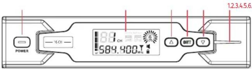
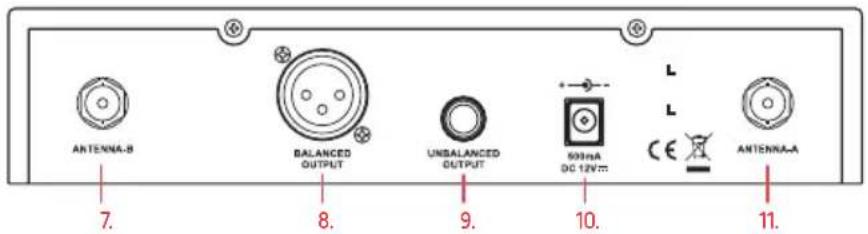
RECEIVER
ULWS-216
- RF indicator
- LCD Screen
- Power button
- Down button
- Set button
-
Up button
-
Antenna B input
- Channel 2 balanced 3-pin XLR output
-
Channel 1 balanced 3-pin XLR output
-
Unbalanced 1/4 in. output (ch. 1 and 2 combined)
- Power supply socket
- Antenna A input

LCD SCREEN
- Output volume level
- Transmitter gain
- Transmitter RF power
- Channel indicator
- Audio level meter
- Channel frequency
- RF input indicator
- Auto-lock icon
- Auto mute indicator

ALSO INCLUDED
- Antenna (×2)
• Antenna extension cables (×2)
• Antenna adapter plugs (×2) - DC power supply
- Carrying case
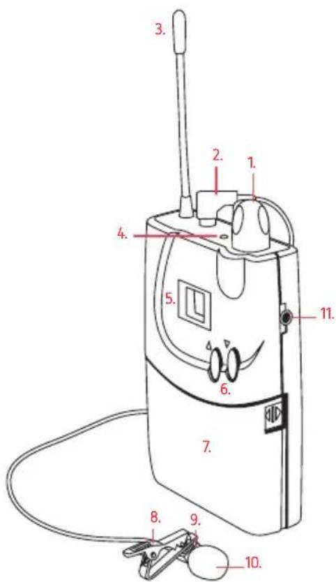
TRANSMITTER
- Level control
- Microphone input
- Antenna
- TX LED
- Channel indicator LED
- Channel up/down buttons
- Battery compartment panel
- Tie clip
- Cardioid lavalier microphone
- Windscreen
- Line-level input
- Charging contacts
- Belt clip
ALSO INCLUDED
AA batteries (×2)
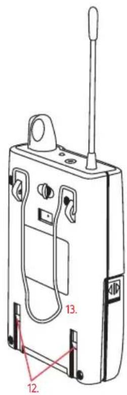
HANDHELD TRANSMITTER
- Grille and windscreen
- Mic capsule
- Anti-roll ring
- LCD screen
- Channel indicator
- Battery meter
- Power switch
- Battery cover
- Battery compartment
- Channel selector button
- Gain level control
- Antenna

PRECAUTIONS

- Please read and follow these instructions, and keep this manual in a safe place.
- Exposure to high sound levels can cause permanent hearing loss. Avoid listening at high volumes for extended periods of time.
- Keep this product away from water and any flammable gases or liquids.
- Handle this product with care.
- Clean this product with only a soft, dry cloth.
- Keep this product away from children.
- Use only parts provided by the manufacturer.
- All images are for illustrative purposes only.
INSTALLING BATTERIES
The transmitter and handheld transmitter are each powered by two AA batteries. To install the batteries, follow these steps:
Transmitter
- Make sure the unit is turned off by rotating the level control knob to the off position.
- Gently squeeze the battery compartment panel by the arrows on both sides, and pull out to swing the panel open.
- Insert fresh batteries in the proper orientations.
- Close the panel completely so it locks into place.
Tip: You can use rechargeable AA batteries with the transmitter, and recharge them by inserting them into the Polsen ULW-BBCH charger (sold separately). Use only rechargeable batteries with the charger. Do not attempt to charge standard batteries—this may result in damage to the unit and void the warranty.
Handheld Transmitter
- Unscrew the battery compartment cover to expose the battery compartment.
- Insert fresh batteries according to the orientation diagram inside the compartment.
- Replace the battery cover by screwing it firmly back into place.
MOUNTING THE RECEIVER
Use the mounting hardware (sold separately) to install the receiver into a standard 19-inch equipment rack.
- With the included screws, mount the angled rack attachments to the sides of the receiver.
- Attach the rack ears to the angled attachments.
- Attach the antenna extension cables to both antenna input jacks.
- Place the antenna plug adapters into the rack holes so the nut is on the outside of the rack, and attach the extension cables.
- Attach the antennas to the plug adapter from the outside of the rack, and tighten the adjustment nut until it is snug against the rack and holds the antenna securely in place.
- Use standard rack screws and washers (not included) to mount the receiver and antenna assembly into your equipment rack.
CONNECTING THE RECEIVER
Balanced XLR Audio Output
Use a balanced XLR cable to connect the output of the receiver to the balanced input on a mixing console.
Unbalanced 1/4-Inch Audio Output
The 1/4 in. phone jack can be connected to an unbalanced aux input of a mixer, guitar amp, or recorder.
OPERATING INSTRUCTIONS
Before you connect the system to your mixing board and talent, you should test and set initial parameters as detailed below:
Connecting the Transmitter and Receiver
RECEIVER
Channel selection:
Follow these steps with the transmitter powered off.
- Press and hold the set button [SET] until the auto lock icon [disappears.
-
Press the set button to make the channel indicator [88] blink.
-
Press the up or down buttons [ ] to select a channel.
- Press set to confirm.
- Look at the RF input indicator [▼] on the LCD screen. If it lights up or flickers, it indicates there's interference on that channel. Select a different channel and repeat these steps until you find an interference-free channel.
Note: If you connect the receiver to a sound system, mute the sound system. Anytime you change channels, remove your headphones, and mute connected sound systems to avoid audible RF noise bursts.
TRANSMITTER
- Connect the lavalier microphone to the transmitter's microphone input, or plug a line-level source such as an audio mixer or mobile device to the transmitter's line-level input.
- Turn on the transmitter by rotating the level control clockwise. You should hear a click and see the channel indicator LED [15]light up.
- Use the channel selector buttons [▲▼] to set the transmitter to the same channel as the receiver (see Selecting Channels on page 14).
Selecting channels:
- Press and hold the up or down button [▲▼] for 2 seconds. The channel number on the LCD display [18] will blink.
- Change the channel with short presses of the up or down buttons while the channel number is blinking.
- The channel number will continue to blink for 6 seconds. The channel number stops blinking to indicate that the channel has been selected.
Once the transmitter and receiver have been set to the same channel, the RF input indicator [Y] will glow.
Setting the Volume
Adjust the level control knob on the transmitter so the audio level meter on the receiver indicates that it's receiving a strong signal without peaking.
On the receiver, press and hold the set button until the auto lock icon disappears. Use the up and down buttons to adjust the volume output level. The objective is to transmit the highest possible level without distortion.
HANDHELD TRANSMITTER
Turn on the handheld transmitter by moving the power switch to the on position. The LCD display will illuminate, showing the selected channel [18] and battery icon[3]
Note: Anytime you change channels, remove your headphones and mute the connected sound systems to avoid audible RF noise bursts.
Setting the transmitter channel:
Important! After you have selected an interference-free channel, set the handheld transmitter to the same channel.
- Remove the battery compartment cover.
- Press and hold the select button. The channel indicator on the LCD display will blink.
- Change the channel with short presses of the select button until the desired channel is displayed. The channel indicator will continue to blink for 10 seconds and then stop to indicate that the channel has been selected.
Note: If you are using multiple ULWS-16 and ULWS-16-H wireless systems, make sure each system is set to a different channel—at least three channels apart as a guard band.
- Adjust the audio output level on the receiver or the input level on your input device as necessary. Make sure a sufficient level is being recorded. The objective is to transmit the highest possible level without distortion for the best signal-to-noise ratio throughout the signal path.
Important! It is not recommended to adjust the gain setting of the handheld transmitter. The gain is preset to the ideal setting. Any volume adjustments should be made on the receiver or on the input device. - When holding the ULW-16-HHT handheld transmitter, hold it in the middle of the transmitter body, not at the end where the antenna is located. Covering the antenna with your hand will degrade the transmission quality.
MOUNTING THE TRANSMITTER
Once you have determined that the transmission quality and level are good, mount the beltpack transmitter to your talent.
- Use the integrated belt clip to secure the transmitter to your talent. Use the included tie clip to place the microphone on your talent.
- If you are connecting to a line-level source, use an appropriate cable to connect to the mono 3.5 mm jack.
Note: The line-level input overrides the microphone input.
The transmitter's TX LED will glow orange when the unit is transmitting, and the receiver's RF indicator LED [■] will glow blue when the unit is receiving a strong radio frequency signal.
RECEIVER OPERATION
Attaching the Antennas
The receiver should always be used with the antennas attached.
Insert an antenna into the antenna input jack on the back of the receiver, and twist the coupling nut a quarter-turn until secure.
To attach the antennas to the receiver when it's mounted into an equipment rack (see Mounting the Receiver on page 11).
Auto Lock
The auto-lock feature ensures that the receiver's setting will not change if the buttons, including the power button, are accidentally pressed or bumped.
To disengage auto lock, press and hold the set button until the auto-lock icon [icon] turns off. You will be able to navigate through the settings by pressing the set button repeatedly. Adjust the values with the up and down buttons [▲▼].
After adjusting the settings values, auto lock engages after 5 seconds of inactivity.
Manual Channel Selection
To select a channel manually:
- Press and hold the set button [SET] until the auto-lock icon [🔒] turns off.
- Press the set button repeatedly until the channel indicator [38] blinks.
- Use the up and down buttons [▲▼] to select the desired channel.
- Press the set button to accept.
Volume
The output volume level adjusts the volume output level that's sent to the mixing board or PA. To adjust the volume:
- Press and hold the set button [SET] until the auto-lock icon turns off.
- Press the set button repeatedly until the volume indicator [ ] blinks.
- Use the up and down buttons [▲▼] to adjust the output volume level.
- Press the set button to accept.
SPECIFICATIONS
SYSTEM
| FREQUENCY RANGE | 584.400 to 602.450 MHz |
| NUMBER OF CHANNELS | 16 |
| FREQUENCY ALLOCATION | Ch. 1 584.400 MHz, Ch. 2 587.500 MHz, Ch. 3 589.575 MHz, Ch. 4 591.050 MHz, Ch. 5 593.425 MHz, Ch. 6 595.200 MHz, Ch. 7 598.450 MHz, Ch. 8 599.650 MHz, Ch. 9 601.275 MHz, Ch. 10 603.775 MHz, Ch. 11 605.500 MHz, Ch. 12 606.750 MHz, Ch. 13 586.025 MHz, Ch. 14 590.525 MHz, Ch. 15 594.150 MHz, Ch. 16 602.450 MHz |
| SWITCHING BANDWIDTH 25 MHz | |
| PEAK DEVIATION ±55 kHz | |
| TOTAL HARMONIC DISTORTION | <0.8% |
| OPERATING DISTANCE | ≤140 ft. (40 m); 300 ft. (91.4 m) in optimum conditions |
RECEIVER
| DYNAMIC RANGE | >102 dB |
| SIGNAL-TO-NOISE RATIO | >98 dB |
| OUTPUT | ULWS-16: 1× XLR, 1× 1/4 in.ULWS-216: 2× XLR, 2× 1/4 in. |
| OUTPUT IMPEDANCE | XLR: 3 kΩ1/4 in.: 3 kΩ |
| AUDIO OUTPUT LEVEL | XLR: +10 dBu1/4 in.: +8 dBu |
| RF SENSITIVITY | <-92 dBm for 30 dB S/N ratio |
| IMAGE REJECTION | >50 dB |
| HOUSING Metal | |
| POWER REQUIREMENT 12 V, 5 A DC | |
| DIMENSIONS (W × H × D) | ULWS-16: 8.3 × 1.7 × 6.75 in. (21.2 × 4.4 × 17.1 cm)ULWS-216: 16 × 1.7 × 6.75 in.(40.6 × 4.4 × 17.1 cm) |
| WEIGHT ULWS-16: 1.7 lb. (771 g) | ULWS-216: 3 lb. (1.4 kg) |
TRANSMITTER
| FREQUENCY RESPONSE | 60 Hz to 18 kHz |
| RF OUTPUT POWER | 10 mW |
| IMAGE REJECTION >55 dBc | |
| MAXIMUM INPUT VOLTAGE 1000 | mV |
| INPUT 1/8 in. (3.5 mm) | |
| POWER SUPPLY Two AA batteries | |
| OPERATING TIME Approximately 8 hr. | |
| DIMENSIONS | 4.4 × 2.6 × 1.1 in. (11.3 × 6.5 × 2.9 cm) |
| WEIGHT | With Batteries: 5 oz. (14.2 g); Without batteries: 3.3 oz. (94 g) |
MICROPHONE
| TRANSDUCER | Back electret condenser |
| POLAR PATTERN | Cardioid |
| FREQUENCY RESPONSE 20 Hz to 16 kHz | |
| SENSITIVITY -47 dB ±3 dB V/Pa | |
| IMPEDANCE | 2000 Ω ±30% |
| MAXIMUM SPL 130 dB | |
| OPERATING VOLTAGE 1.5 A, 10 V | |
| HEAD DIAMETER 1/4 in. (6.3 mm) | |
| CABLE LENGTH 42 in. (106.6 cm) | |
HANDHELD TRANSMITTER
| TRANSDUCER | Dynamic |
| POLAR PATTERN | Cardioid |
| FREQUENCY RESPONSE 60 Hz to 18 kHz | |
| RF OUTPUT POWER 10 mW | |
| IMAGE REJECTION | >55 dBc |
| SIGNAL-TO-NOISE RATIO 102 dB | |
| TOTAL HARMONIC DISTORTION | <1% |
| MAXIMUM INPUT VOLTAGE 1000 | mW |
| POWER SUPPLY Two AA batteries | |
| OPERATING TIME Approximately 8 hr. | |
| DIMENSIONS (H × W × L) | 2.1 × 2 × 10 in. (5.3 × 5.1 × 25.4 cm) |
| WEIGHT | With batteries: 15.6 oz. (441 g); Without batteries: 13.6 oz. (385 g) |
TROUBLESHOOTING
Because of the widespread use of wireless technology, many RF signals pervade our environment. This can sometimes make it challenging to work with wireless systems like the ULWS-16 and ULWS-216. In some cases, you may be doing everything correctly and still be experiencing some difficulties. Included in this troubleshooting guide are some tools and tips for dealing with RF signals and interference.
| Problem Possible Cause Solution Comment | |||
| The audio is noisy or distorted.This can include drop-outs, white noise, bursts, pops, and clicks. | The RF signal is weak. | Make sure there is an unobstructed line of sight between the receiver's and the transmitter's antennas. Keep in mind that your body, wardrobe, and onstage sets are possible obstructions.Make sure the receiver and transmitter are within the 100-foot (30.5 m) range.If there are obstructions, you may need to move closer.When using the ULW-16-HHT handheld transmitter, make sure you're holding it in the middle of the body and that your hand isn't covering the antenna, located at the end of the transmitter. | If the RF indicator blinks, the signal is not strong enough. Check the audio.The RF indicator should consistently glow blue. |
| The audio is noisy or distorted. This can include drop outs, white noise, bursts, pops, and clicks. (Continued) | The input level on the recorder or mixer is too high. | Turn down the audio input level on your recording device.Make sure the output of the receiver is plugged into the line-level input on your mixer, and that the line/ mic switch on your mixer is set to line.Turn down the gain on your mixer.If there is no adjustment on the device, adjust the microphone level on the transmitter. Keep this level as high as possible without distortion. | For general dialogue, try to keep the microphone-level in the target-level mark. Because the talent can adjust this, make sure the talent is aware of the receiver and knows not to change the controls unless instructed otherwise.Make note of your level settings before recording. |
| The batteries are weak. | Replace the batteries in the transmitter or handheld transmitter. | Make sure to bring extra batteries with you.You should replace the batteries on every shoot.Rechargeable batteries will save money over time, and NiCd batteries generally have a long performance time. | |
| The unit will not turn on. | The batteries are dead. | Replace the batteries in the proper unit. Make sure to bring extra batteries with you. | |
| There is no audio or the audio is intermittent. | The batteries in one of the units are dead. | Replace the dead batteries in the proper unit. Make sure to bring extra batteries with you. | |
| The audio cable is unreliable, or the cable or microphone is unplugged. | Check the audio cable to make sure it's reliable and is not shorting.Check all cables to make sure they are completely plugged into the proper inputs. | ||
| The line source is off or not playing back audio. | If you are transmitting a line-level signal, make sure there is audio coming out of the line-source device. | ||
| The line-level input overrides the microphone input. | If you want to record via the microphone input, make sure there is nothing plugged into the line-level input. | ||
| There is no audio or the audio is intermittent. (Continued) | The audio levels are too low. | Turn up the microphone level on the transmitter. The target level mark on the transmitter is a good start.Adjust the headphone level on the receiver and listen to make sure the signal is transmitting.Turn up the input levels on your recording device or mixer. | |
| The transmitter and receiver are set to different channels. | Make sure the transmitter, handheld transmitter, receiver, and all other devices in your audio chain are turned on and configured to the proper settings. | ||
| Too much ambiance is being picked up. | The microphone may be picking up too much ambiance. | Make sure the microphone is as close as possible to the subject. | Approximately inches (15.2 cm) from the subject is usually good microphone placement, but you may need to experiment. |
ONE-YEAR LIMITED WARRANTY
This Polsen product is warranted to the original purchaser to be free from defects in materials and workmanship under normal consumer use for a period of one (1) year from the original purchase date or thirty (30) days after replacement, whichever occurs later. The warranty provider's responsibility with respect to this limited warranty shall be limited solely to repair or replacement, at the provider's discretion, of any product that fails during normal use of this product in its intended manner and in its intended environment. Inoperability of the product or part(s) shall be determined by the warranty provider. If the product has been discontinued, the warranty provider reserves the right to replace it with a model of equivalent quality and function.
This warranty does not cover damage or defect caused by misuse, neglect, accident, alteration, abuse, improper installation or maintenance. EXCEPT AS PROVIDED HEREIN, THE WARRANTY PROVIDER MAKES NEITHER ANY EXPRESS WARRANTIES NOR ANY IMPLIED WARRANTIES, INCLUDING BUT NOT LIMITED TO ANY IMPLIED WARRANTY OF MERCHANTABILITY OR FITNESS FOR A PARTICULAR PURPOSE. This warranty provides you with specific legal rights, and you may also have additional rights that vary from state to state.
To obtain warranty coverage, contact the Polsen Customer Service Department to obtain a return merchandise authorization ("RMA") number, and return the defective product to Polsen along with the RMA number and proof of purchase. Shipment of the defective product is at the purchaser's own risk and expense.
For more information or to arrange service, visit www.polsenaudio.com or call Customer Service at 212-594-2353.
Product warranty provided by the Gradus Group.
www.gradusgroup.com
Polsen is a registered trademark of the Gradus Group. © 2018 Gradus Group LLC. All Rights Reserved.

POLSEN® A Gradus Group Brand
- CONTENTS
- OVERVIEW
- RECEIVER
- ULWS-16
- ULWS-216
- LCD SCREEN
- ALSO INCLUDED
- TRANSMITTER
- HANDHELD TRANSMITTER
- PRECAUTIONS
- INSTALLING BATTERIES
- MOUNTING THE RECEIVER
- CONNECTING THE RECEIVER
- Balanced XLR Audio Output
- Unbalanced 1/4-Inch Audio Output
- OPERATING INSTRUCTIONS
- Connecting the Transmitter and Receiver
- Selecting channels:
- Setting the Volume
- Setting the transmitter channel:
- MOUNTING THE TRANSMITTER
- RECEIVER OPERATION
- Attaching the Antennas
- Auto Lock
- Manual Channel Selection
- Volume
- SPECIFICATIONS
- TROUBLESHOOTING
- ONE-YEAR LIMITED WARRANTY
Brand : Polsen
Model : ULWS-216
Category : Charger