ATW-2192XBITH - Headphones Audio-Technica - Free user manual and instructions
Find the device manual for free ATW-2192XBITH Audio-Technica in PDF.

User questions about ATW-2192XBITH Audio-Technica
0 question about this device. Answer the ones you know or ask your own.
Ask a new question about this device
Download the instructions for your Headphones in PDF format for free! Find your manual ATW-2192XBITH - Audio-Technica and take your electronic device back in hand. On this page are published all the documents necessary for the use of your device. ATW-2192XBITH by Audio-Technica.
USER MANUAL ATW-2192XBITH Audio-Technica
Frequency-agile True Diversity UHF Wireless System
Installation and Operation
flowchart
graph LR
    A["POWER"] --> B["ON OFF"]
    B --> C["Digital Display"]
    C --> D["UP"]
    C --> E["DOWN"]
    D --> F["SET/SCAN"]
    E --> F
This device complies with part 15 of the FCC Rules. Operation is subject to the condition that this device does not cause harmful interference.
This device complies with INDUSTRY CANADA R.S.S. 210, en conformité avec IC: RSS-210/CNR210. Operation is subject to the following conditions: 1) This device may not cause harmful interference and 2) this device must accept any interference received, including interference which may cause undesired operation.
Hereby Audio-Technica declares that this device complies with the essential requirements and other relevant provisions of the R&TTE directive 1999/5/EC
FCC Notice
Caution
You are cautioned that any changes or modifications not expressly approved in this manual could void your authority to operate this equipment.
Note: This equipment has been tested and found to comply with the limits for a Class B digital device, pursuant to part 15 of the FCC Rules. These limits are designed to provide reasonable protection against harmful interference in a residential installation. This equipment generates, uses and can radiate radio frequency energy and, if not installed and used in accordance with the instructions, may cause harmful interference to radio communications. However, there is no guarantee that interference will not occur in a particular installation. If this equipment does cause harmful interference to radio or television reception, which can be determined by turning the equipment off and on, the user is encouraged to try to correct the interference by one or more of the following measures:
- Reorient or relocate the receiving antenna.
- Increase the separation between the equipment and receiver.
- Connect the equipment into an outlet on a circuit different from that to which the receiver is connected.
- Consult the dealer or an experienced radio/TV technician for help.
A copy of the user's manual and DoC can be found at www.audio-technica.com.
CAUTION! Electrical shock can result from removal of the receiver cover. Refer servicing to qualified service personnel. No user-serviceable parts inside.
- To prevent fire or shock hazard, do not expose this appliance to rain or moisture.
- To prevent fire, do not place any naked flame sources (such as lighted candles) on the apparatus.
- To prevent fire, do not cover the ventilation of the apparatus with newspaper, tablecloths, curtains etc.
- Do not expose this apparatus to drips or splashes.
- Do not place any objects filled with liquids, such as vases, on the apparatus.
- Do not install this apparatus in a confined space such as a bookcase or similar unit.
- The apparatus should be located close enough to the AC outlet so that you can easily grasp the AC adapter at any time. In case of emergency, disconnect the AC adapter quickly.
- Danger of explosion if battery is incorrectly replaced. Replace only with the same or equivalent type.
- Always consider environmental issues and follow your local regulations when disposing of batteries. Do not expose batteries to excessive heat.
The circuits inside the receiver and transmitter have been precisely adjusted for optimum performance and compliance with federal
regulations. Do not attempt to open the receiver or transmitter. To do so will void the warranty, and may cause improper operation.
Notice to individuals with implanted cardiac pacemakers or AICD devices:
Any source of RF (radio frequency) energy may interfere with normal functioning of the implanted device. All wireless microphones have low-power transmitters (less than 0.05 watts output) which are unlikely to cause difficulty, especially if they are at least a few inches away. However, since a "body-pack" mic transmitter typically is placed against the body, we suggest attaching it at the belt, rather than in a shirt pocket where it may be immediately adjacent to the medical device. Note also that any medical-device disruption will cease when the RF transmitting source is turned off. Please contact your physician or medical-device provider if you have any questions, or experience any problems with the use of this or any other RF equipment.
RF Interference
Please note that wireless frequencies are shared with other radio services. According to Federal Communications Commission regulations, "Wireless microphone operations are unprotected from interference from other licensed operations in the band. If any interference is received by any Government or non Government operation, the wireless microphone must cease operation..." If you need assistance with operation or frequency selection, please contact your dealer or Audio-Technica. Extensive wireless information also is available at www.audio-technica.com.
Thank you for choosing an Audio-Technica professional wireless system. You have joined thousands of other satisfied customers who have chosen our products because of their quality, performance and reliability. This Audio-Technica wireless microphone system is the successful result of years of design and manufacturing experience.
Each 2000 Series wireless system provides a choice of 10 PLL synthesized UHF frequencies in one of five UHF frequency ranges, available for flexible performance in a wide variety of regions worldwide:
Frequency Range
Band D 656.125 - 678.500 MHz
Band E 795.500 - 805.875 MHz
Band F 854.900 - 864.900 MHz
Band G 722.125 - 744.500 MHz
Band I 487.125 - 506.500 MHz
Band U 606.500 - 629.900 MHz
The band letter reference at the end of 2000 Series Stock Numbers indicates what band system/component operates in. For simplicity, model numbers used throughout this manual will reference only the basic model number without the band indications.
Each wireless system includes a receiver and either a body-pack or handheld transmitter. UniPak ^® body-pack transmitter systems include accessory microphones for particular applications. All A-T Wireless Essentials ^® microphones and cables, available separately, are pre-terminated for use with any Audio-Technica 2000 Series wireless system.
The ATW-R2100b receiver features true diversity reception. Two antennas feed two completely independent RF sections on the same frequency; automatic logic circuitry continuously compares and selects the superior received signal, providing better sound quality and reducing the possibility of interference and dropouts. The receiver also offers a switchable output attenuator to reduce the level of the output signal by 12 dB for flexible use with a variety of system configurations.
Switchable antenna power is also provided. Soft-touch controls provide convenient access to selection of operating frequency and automatic scanning, while an LCD information display provides constant monitoring of system operation. The receiver is half-width for a standard 1U 19" rack mount; rack-mount adapters are included. Two receivers can be mounted side by side, using an optional AT8630 joining-plate kit.
The versatile ATW-T210a UniPa® body-pack transmitter has both low- and high-impedance inputs plus a bias connection, for use with dynamic and electret condenser microphones, as well as Hi-Z instrument pickups. The UniPa® transmitter also offers separate trim controls for instrument and microphone, plus switchable high/low RF power.
The ATW-T220a handheld dynamic microphone/transmitter features the same element used in the PRO 41 dynamic handheld microphone created for professional live-sound venues. It also offers switchable high/low RF power. Both the ATW-T210a UniPal® and ATW-T220a handheld transmitters also offer charging contacts so the units can be placed in an optional recharging station for multi-transmitter charging.
For economical operation and wide availability, transmitters in the 2000 Series use two 1.5V AA alkaline batteries or rechargeable two AA NiMH batteries for use with Audio-Technica's ATW-CHG2 Recharging Station. Both transmitters have battery condition indicators. 2000 Series receivers feature a sophisticated Tone Lock™ tone squelch system that opens the receiver's audio output only when a 2000 Series transmitter is detected, reducing the possibility of interference. As a result, 2000 Series transmitters and receivers must be used together and should not be used with components from other Audio-Technica wireless systems, or with those of other manufacturers.
Please note that in multiple-system applications there must be a transmitter-receiver combination set to a separate channel (frequency) for each input desired (only one transmitter for each receiver).
Because the wireless frequencies are within UHF TV frequency bands, only certain channels (operating frequencies) may be useable in a particular geographic area. The 10 channels (operating frequencies) per band that are used in the 2000 Series have been selected for multi-channel compatibility. Subject to frequency availability in a particular geographic area, any of these 10 channels may be used together. The operating frequencies that correspond to each of the 10 channels are listed on page 10.
Receiver Installation
Location
For best operation the receiver should be at least 3 ft. (1 m) above the ground and at least 3 ft. away from a wall or metal surface to minimize reflections. The transmitter should be at least 3 ft. from the receiver, as shown in Figure A. Keep antennas away from noise sources such as digital equipment, motors, automobiles and neon lights, as well as away from large metal objects.
Fig. A
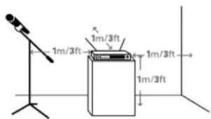
text_image
1m/3ft 1m/3ft 1m/3ft 1m/3ftOutput Connections
There are two audio outputs on the back panel: balanced and unbalanced. Use shielded audio cable for the connection between the receiver and the mixer. If the input of the mixer is a 14 jack, connect a cable from the 14 unbalanced audio output on the back of the receiver housing to the mixer. If the input of the mixer is an XLR-type input, connect a cable from the balanced XLR-type audio output on the back panel to the mixer. The two isolated audio outputs permit simultaneous feeds to both unbalanced and balanced inputs. For example, both a guitar amp and a mixer can be driven by the receiver.
Antennas
Attach the included pair of UHF antennas to the antenna input jacks. The antennas are normally positioned in the shape of a "V" (both 45° from vertical) for best reception.
Accessory antennas can be remotely located from the receiver. However, due to signal loss in cables at UHF frequencies, use the lowest-loss RF cables practical for any cable runs over 25 feet. RG8-type is a good choice. Use only copper-shielded cable, not CATV-type foil-shielded wire. Audio-Technica offers quality RF cables in four lengths, as well as remote antennas; see audio-technica.com for a wide selection of wireless system accessories.
Antenna Power
The antenna input jacks also can provide +12V DC output on their center pins to power inline RF devices. A maximum of 60 mA can be drawn from each of the jacks. While an accidental short-circuit will not harm the internal 12V supply, make certain that an antenna cable shield does not contact the center conductor. Antenna Power is selected by a switch on the back of the ATW-R2100b Receiver. The unit is shipped with the switch in the "off" position.
Note: the antennas included with the ATW-R2100b Receiver do not require power. If you have an antenna system that requires power (such as powered antennas or active combiners or splitters) switch the Antenna Power switch to the "on" position.
Power Connections
Connect the included AC adapter to the DC power input on the back of the receiver. Loop the small cord from the DC plug over the cord hook above the jack, to keep the plug from being detached by an accidental tug on the cord. Operation of the receiver is controlled by the front-panel Power switch.
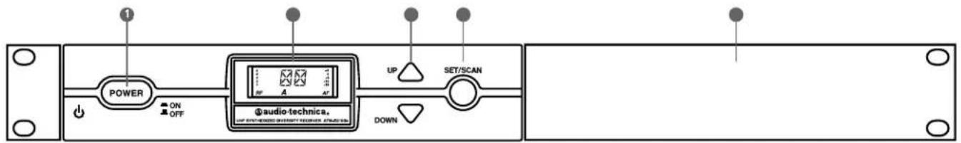
Receiver Controls and Functions
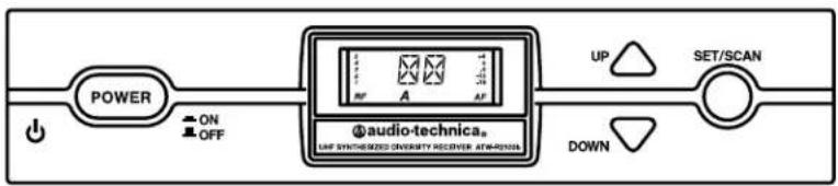
Fig. B - Front Panel Controls and Functions
text_image
POWER ON OFF AUDIO-TECHNICA. UP WITH-ENDS SHEET/SHORES 4000000 UP SET/SCAN DOWN- POWER SWITCH: Press the Power switch in to turn the receiver on. The LCD window will light, and the operating channel number will be displayed in the window. To turn the receiver off, press the Power switch again.
- LCD WINDOW: Liquid Crystal Display indicates channel setting and operational readings. See Fig. C for examples.
- UP/DOWN BUTTONS: Press Up or Down arrow buttons to arrive at desired channel. The selected number will flash on and off. Press and hold Set/Scan button to set the channel (operating frequency).
- SET/SCAN BUTTON: Two distinct operations are associated with this button:
Touch: A momentary press of the Set/Scan button. Hold: A press and hold (about two seconds) of the Set/Scan button.
The Set/Scan button can be used in two ways: Manual Set Mode, to permit selection of an operating channel; and Automatic Scan/Set Mode, to initiate the automatic channel scan and selection, as follows:
Manual Set Mode: After using the Up or Down arrow button to arrive at desired channel, hold the Set/Scan button to set the channel. NOTE: Before the channel has been set, a touch of the Set/Scan button will revert the channel to its previous setting.
Automatic Scan/Set Mode: Hold the Set/Scan button. The Automatic Scan/Set Mode will automatically scan for and set the next open channel.
- MOUNTING ADAPTERS: For mounting the receiver in any standard 19" rack. Attach adapters to the receiver with the screws supplied and remove the four receiver feet. (Use optional AT8630 joining-plate kit to mount two ATW-R2100b receivers side-by-side.)
Fig. C - Receiver LCD Window Display

text_image
5 4 3 2 1 RF A +4 0 -6 -12 -18 AF 6- RF SIGNAL LEVEL INDICATOR: Shows the strength of the RF signal received from the transmitter.
- TUNER OPERATION INDICATOR: Indicates which Tuner (A or B) has the better reception and is in operation.
- CHANNEL DISPLAY: Shows which channel is selected.
- AF LEVEL INDICATOR: Shows the audio modulation level of the received signal.
Fig. D - Rear Panel Controls and Functions

text_image
ANT. B 12V 50mA OFF ON ANT POWER MIN MAX SQUELCH ANT. A 12V 50mA -12dB AF LEVEL GROUND LIFT GROUND GROUND AF OUT BALANCED AF OUT UNBALANCED 12-3W DC 50mA 20- ANTENNA INPUT JACK: BNC-type antenna connector for Tuner "B." Attach the antenna directly, or extend it with a low-loss antenna cable. See the "Antennas" section on page 3 for more details.
- ANTENNA POWER SWITCH: Two-position switch turns on/off the 12V DC antenna power for use with powered antennas or accessories. Factory setting is off. See the "Antennas" section on page 3 for more details.
- SQUELCH CONTROL: Adjusts level of noise-muting circuit (preset at factory but can be adjusted as circumstances warrant). Factory setting is full counterclockwise (minimum).
- ANTENNA INPUT JACK: Input for Tuner "A." Attach the supplied antenna directly, or extend it to an accessory antenna with a low-loss antenna cable.
-
AF OUTPUT ATTENUATOR: Two-position switch adjusts audio output level of the balanced (XLR) audio output jack with attenuation of 0 dB or -12 dB. Factory setting is 0 dB.
-
AF LEVEL CONTROL: Adjusts audio output level of both AF output jacks. Factory setting maximum output—fully clockwise.
- GROUND LIFT SWITCH: Disconnects the ground pin of the balanced output jack (15) from ground. Normally, the switch should be to the left (ground connected). If hum caused by a ground loop occurs, slide switch to the right (ground lifted). Factory setting is ground connected.
- BALANCED AUDIO OUTPUT JACK: XLRM-type connector. A standard 2-conductor shielded cable can be used to connect the receiver output to a balanced microphone-level input on a mixer or integrated amplifier.
- UNBALANCED AUDIO OUTPUT JACK:1/4" phone jack. Can be connected to an unbalanced aux-level input of a mixer, guitar amp or tape recorder.
- POWER INPUT JACK: Connect the DC plug from the included in-line AC adapter.
- CORD HOOK: Loop the small DC cord around the cord hook to keep the DC plug from pulling out accidentally.
Transmitter Controls and Functions
Battery Selection
Two 1.5V AA alkaline batteries or rechargeable AA NiMH batteries for use with Audio-Technica's ATW-CHG2 Recharging Station are recommended.
UniPak® Transmitter Battery Installation
- Open the transmitter door by pressing gently on the side-cover indentations and pulling back the hinged cover.
- Lift the battery-keeper arm, and carefully insert two fresh 1.5V AA alkaline batteries or rechargeable AA NiMH batteries, observing correct polarity as marked inside the battery compartment.
- Close the battery-keeper arm.
- Close the transmitter door.
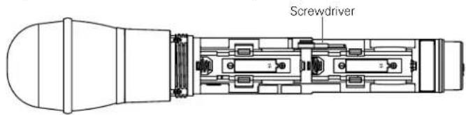
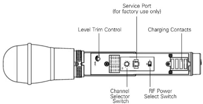
Fig. E - UniPak® Transmitter Open

text_image
Antenna Power-on LED Service Port (for factory use only) RF Power Select Switch Channel Selector Switch Audio Input Jack Instrument/ Microphone Level Trim Controls Battery-keeper Arm with Screwdriver attached Transmitter Door Charging ContactsHandheld Transmitter Battery Installation
- While holding the upper part of the transmitter body below the ball-screen, unscrew the lower body cover, slide it downward, and remove it to expose the battery compartment.
- Observe correct polarity as marked inside the battery compartment and carefully insert two fresh 1.5V AA alkaline batteries or rechargeable AA NiMH batteries. Make certain the batteries are fully seated in the battery compartment. (Fig. F)
- Slide the lower body cover back up the body, then screw the housing together. Do not overtighten.
Note: Remove batteries from the handheld transmitter starting at the bottom end, where finger indents in the battery housing are provided for easy grip.
Fig. F – Handheld Transmitter Battery Compartment
text_image
ScrewdriverBattery Indicator
After the battery is installed, turn on the power switch (located on the bottom of the handheld transmitter and on the top of the UniPak transmitter). The battery indicator LED (Fig. G/H) should turn red. If it does not, the batteries are installed incorrectly or they are dead.
Fig. G - UniPak Transmitter Top View
Fig. H - Handheld Transmitter Bottom View
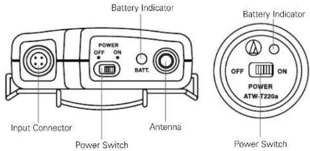
text_image
Battery Indicator POWER OFF ON BATT. Input Connector Power Switch Antenna Battery Indicator OFF ON POWER ATW-T220a Power SwitchUniPak ^® Transmitter Input Connection
Connect an audio input device (microphone or guitar cable) to the audio input connector on the top of the transmitter. A number of Audio-Technica professional microphones and cables are available separately, pre-terminated with a UniPak input connector.
UniPak® Transmitter Antenna
The ATW-T210a UHF UniPak® body-pack transmitter includes one field-replaceable antenna mounted on the transmitter. The antenna simply screws into the transmitter's antenna fitting. Check the installed antenna occasionally to make certain it is snugly attached (only finger-tight). If the received signal is marginal, experiment with different transmitter positions on your body or instrument or try repositioning the receiver. Do not attempt to modify the transmitting antenna. Replace it only with the same parts, available from the Audio-Technica Service Department.
System Operation
Switch on the receiver. Do not switch on the transmitter yet.
Receiver On...
The LCD display will light up. If two or more of the RF LCD segments light up at this point, there may be RF interference in the area. If this occurs, change operating channels (select another frequency).
How to Make Operating Channel Changes
Operating channel changes (frequency changes) may be made in two ways: manually and automatically.
To change channel manually
-
Use the Up/Down arrow buttons to reach the desired channel number.
-
Hold the Set/Scan button until the channel number stops flashing to set the receiver to the channel indicated. NOTE: Before the channel has been set, a touch (momentary press) of the Set/Scan (rather than a hold) will revert the channel to its previous setting.
To change channel automatically
- Hold the Set/Scan button. The Automatic Scan/Set Mode will automatically scan for and set the next open channel. LCD screen will flash "FS" four times to indicate start of scan. "E1" will show on the receiver display when no further usable frequencies remain in the 10 channel frequency list.
Transmitter On...
Before turning on the transmitter, use the provided screwdriver to set the transmitter channel selector switches (Fig. E/I) to the same numbers as those displayed on the receiver. Always turn the transmitter off when changing channels (frequencies).
The transmitters have a two-position, on-off power switch. When the switch is "On," the transmitter produces both RF and audio.
The transmitters have a two-position RF power select switch, offering low/high transmission modes to conserve battery life/maximize power. Factory setting is high.
There is about a half-second delay after the transmitter is switched to the "On" position before the receiver's Tone Lock squelch un-mutes the receiver.
When the transmitter is switched on and in normal operation, the receiver's RF signal level indicators will display as dark segments (signal strength indicators) from bottom to top at the left side of the LCD display.
Setting Levels
Correct adjustment of transmitter audio input, receiver audio output, and mixer/amplifier input and output levels is important for optimum system performance.
ATW-T220a Handheld Transmitter
The 2000 Series handheld transmitter has factory pre-set audio input levels. Factory setting is full clockwise, maximum gain.
- While speaking/singing into the microphone at typically loud levels, check the AF meter levels on the receiver. If all five AF meter bars are consistently illuminated and distortion is heard through the system, it may be necessary to adjust the transmitter audio input level.
- To adjust the transmitter audio input level, unscrew the lower body cover and slide it downwards, exposing the screwdriver and level trim control (Fig. 1). Remove the screwdriver and gently turn the level trim control counterclockwise until the topmost receiver AF level meter bar is illuminated only on audio peaks.
- Return the screwdriver to its clip and close and secure the lower body. No further transmitter gain adjustments should be needed, as long as the acoustic input does not change significantly.
CAUTION! The small trimmer controls are delicate; use only the supplied screwdriver. Do not force the trimmers beyond their normal 180° range of rotation. Return the screwdriver to its storage clip when not in use.
Fig. I – Handheld Transmitter Interior View
text_image
Service Port (for factory use only) Level Trim Control Charging Contacts Channel Selector Switch RF Power Select Switch
text_image
ScrewdriverSetting Levels (Continued)
ATW-T210a UniPak ^10 Transmitter
Trimmer adjustments in the UniPak ^® transmitter (Fig. E) will enable you to use microphones or instruments with different output levels.
- For MIC: Set microphone level trim control fully clockwise (maximum) and instrument level trim control fully counterclockwise (minimum). Factory setting is fully clockwise (maximum).
For INSTRUMENT: Set instrument level trim control fully clockwise (maximum) and microphone level trim control fully counterclockwise (minimum). Factory setting is fully clockwise (maximum). - Set the receiver's AF Level control to its full clockwise position (maximum). See Figure D on page 5.
- Plug the mic or instrument into the transmitter and power up the system.
- For MIC: Make an initial adjustment of the mixer's level controls that will allow audio through the system.
For INSTRUMENT: Make an initial adjustment of the instrument amplifier input level control that will allow audio through the system.
- For MIC: While speaking/singing into the microphone at typically loud levels, check the AF meter levels on the receiver. If all five meter bars are consistently illuminated and distortion is heard through the system, it may be necessary to adjust the UniPak transmitter audio input level. To adjust the transmitter audio input level, gently turn the microphone level trim control counterclockwise until the topmost receiver AF level meter bar is illuminated only on audio peaks.
For INSTRUMENT: While playing the instrument at typically loud levels, check the AF meter levels on the receiver. If all five meter bars are consistently illuminated and distortion is heard through the system, it may be necessary to adjust the UniPak transmitter audio input level. To adjust the transmitter audio input level, gently turn the instrument level trim control counterclockwise until the topmost receiver AF level meter bar is illuminated only on audio peaks.
- For MIC: While again speaking/singing into the microphone at typically loud levels, adjust the mixer's input trim control so the highest sound pressure level going into the microphone causes no input overload in the mixer, and yet permits the mixer's channel and output level controls to operate in their "normal" range (not set too high or too low).
For INSTRUMENT: While again playing the instrument at typically loud levels, adjust the receiver's AF Level control so the highest signal level causes no input overload in the instrument amplifier and yet permits the amplifier's input level controls to operate in their "normal" range (not set too high or too low).
Note: If the mixer cannot be adjusted to operate in its normal range without distortion, adjust the receiver's AF Level Control (turn counterclockwise) until the mixer/ amplifier is no longer overloaded.
Fig. E - UniPak® Transmitter Open
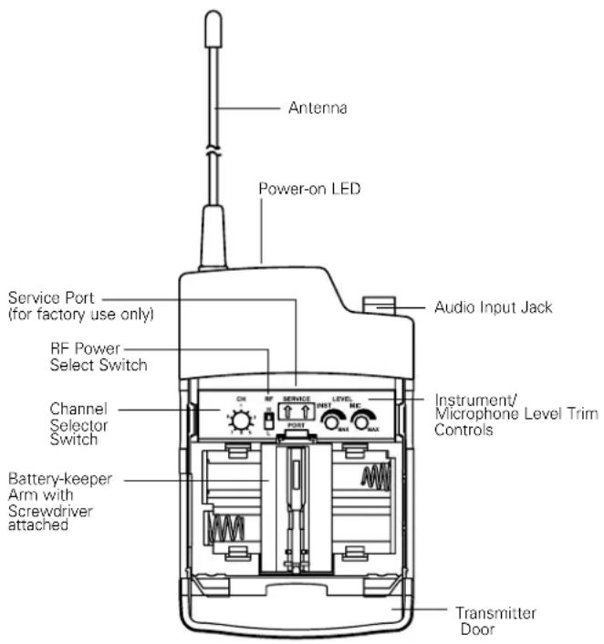
text_image
Antenna Power-on LED Service Port (for factory use only) RF Power Select Switch Channel Selector Switch Battery-keeper Arm with Screwdriver attached Audio Input Jack Instrument/ Microphone Level Trim Controls Transmitter DoorReceiver Squelch
The squelch control on the back panel of the receiver is preset at the factory for best system performance (factory setting is full counterclockwise), but can be adjusted if you must use the system in an area with considerable RF interference. If there is interference in the audio, and changing the channel is not an option, adjust the squelch control so the system will receive the signal from your transmitter but will "squelch" or eliminate the unwanted background RF noise. This adjustment can cause a reduction in useable range of the wireless transmitter, so set the control to the lowest position that reliably mutes the unwanted RF signals.
Specifications ^†
Overall System
| UHF Operating Frequencies | |
| Frequency Range | Number of Channels |
| Band D: 656.125 to 678.500 MHz | 10 |
| Band E: 795.500 to 805.875 MHz | 10 |
| Band F: 854.900 to 864.900 MHz | 10 |
| Band G: 722.125 to 744.500 MHz | 10 |
| Band I: 487.125 to 506.500 MHz | 10 |
| Band U (A): 606.500 to 613.300 MHz | 10 |
| Band U (B): 614.300 to 629.900 MHz | 10 |
Not all frequencies are available in all areas. Please check with local regulations.
| Modulation Mode | FM |
| Maximum Deviation | ±40 kHz |
| Dynamic Range | >110 dB (A-weighted), typical |
| Total Harmonic Distortion | < 1% (at 1 kHz, ±20 kHz deviation) |
| Operating Range | 100 m (300'), typical |
| Open range environment with no interfering signals. | |
| Operating Temperature Range | 5°C to +45°C |
| Battery and LCD performance may be reduced at very low temperatures. | |
| Frequency Response | 100 Hz to 15 kHz (+1 dB, -3 dB) |
ATW-R2100b Receiver
| Receiving System | True diversity |
| Image Rejection | 60 dB nominal, 55 dB minimum |
| RF Sensitivity | 20 dBuV at 60 dB S/N ratio(50 ohms termination) |
| Maximum Output Level | |
| XLR, balanced: | +9 dBV |
| 1⁄4" (6.3 mm), unbalanced: | +4 dBV |
| Balanced Audio Output Attenuator | Two position switch: 0 / -12 dB |
| Antenna Input | BNC-type, 50 ohmsBias voltage 12V DC, 60 mA, each |
| Power Requirements | 12-18V DC, 500 mA |
| Dimensions | 210.0 mm (8.27") W x162.2 mm (6.39") D x44.0 mm (1.73") H |
| Not including BNC connectors or feet. | |
| Net Weight | 1.0 kg (35.3 oz), without accessories |
| Accessories Included | Two flexible UHF antennas;AC adapter (country dependent);rack-mount adapters |
ATW-T210a UniPak® Transmitter
| RF Power Output (50 ohms) | High: 30 mW, Low: 10 mW (switchable) |
| Spurious Emissions | Following federal and national regulations |
Input Connection  | Four-pin Locking ConnectorIND, Pin 2: INST INPUT, Pin 3: MIC INPUT, Pin 4: DC BIAS +9V |
| Batteries | Two 1.5V AA alkaline (not included) or two 1.2V AA NiMH (not included) |
| Recharging power for NiMH batteries (with ATW-CHG2) | |
| U.S./Canada/Latin America: 3.2 V DC---230 mA x2 | |
| Other world areas: 3.2 V DC---320 mA x2 | |
| Battery Life | High: 7 hours (alkaline)Low: 9 hours (alkaline) |
| Depending on battery type and use pattern. | |
| Dimensions | 66.0 mm (2.60") W x22.5 mm (0.89") D x92.3 mm (3.63") H |
| Net Weight | 81 g (2.9 oz), without batteries |
ATW-T220a Handheld Transmitter
| RF Power Output (50 ohms) | High: 30 mW; Low: 10 mW, (switchable) |
| Spurious Emissions | Following federal and national regulations |
| Microphone Element | Dynamic cardioid |
| Batteries | Two 1.5V AA alkaline (not included) or two 1.2V AA NiMH (not included) |
| Recharging power for NiMH batteries (with ATW-CHG2) | |
| U.S./Canada/Latin America: 3.2 V DC---230 mA x2 | |
| Other world areas: 3.2 V DC---320 mA x2 | |
| Battery Life | High: 7 hours (alkaline)Low: 9 hours (alkaline) |
| Depending on battery type and use pattern. | |
| Dimensions | 232.0 mm (9.13") long,48.0 mm (1.89") diameter |
| Net Weight | 252 g (8.9 oz), without batteries |
| Accessory Included | AT8456a Quiet-FlexTM stand clamp |
† In the interest of standards development, A.T.U.S. offers full details on its test methods to other industry professionals on request. Specifications are subject to change without notice.
2000 Series Frequency Channel Plan
Band D
| Channel | Frequency-MHz |
| 1 656.125 | |
| 2 659.375 | |
| 3 660.000 | |
| 4 662.125 | |
| 5 665.125 | |
| 6 669.750 | |
| 7 671.500 | |
| 8 677.000 | |
| 9 678.125 | |
| 10 678.500 |
Band E
| Channel | Frequency-MHz |
| 1 | 795.500 |
| 2 | 795.825 |
| 3 | 797.825 |
| 4 | 798.675 |
| 5 | 800.400 |
| 6 | 800.975 |
| 7 | 803.850 |
| 8 | 804.400 |
| 9 | 804.700 |
| 10 | 805.875 |
Band F
| Channel | Frequency-MHz |
| 1 863.100 | |
| 2 863.500 | |
| 3 864.100 | |
| 4 864.900 | |
| 5 854.900 | |
| 6 855.275 | |
| 7 855.900 | |
| 8 856.175 | |
| 9 858.200 | |
| 10 861.750 |
Band G
| Channel | Frequency-MHz |
| 1 | 722.125 |
| 2 725.375 | |
| 3 726.000 | |
| 4 728.125 | |
| 5 731.125 | |
| 6 735.750 | |
| 7 737.500 | |
| 8 743.000 | |
| 9 744.125 | |
| 10 744.500 |
Band I
| Channel | Frequency-MHz |
| 1 487.125 | |
| 2 487.625 | |
| 3 488.875 | |
| 4 491.750 | |
| 5 494.375 | |
| 6 495.375 | |
| 7 501.375 | |
| 8 503.375 | |
| 9 505.750 | |
| 10 506.500 |
Band U (A)*
| Channel | Frequency-MHz |
| 1607.625 | |
| 2608.875 | |
| 3609.575 | |
| 4610.400 | |
| 5611.675 | |
| 6612.825 | |
| 7606.500 | |
| 8606.750 | |
| 9607.125 | |
| 10613.300 |
* Please note that the frequency range 608-614 MHz (Plan A) is illegal to use in many countries due to radio astronomy. Please check your local regulations.
Band U (B)
| Channel | Frequency-MHz |
| 1614.300 | |
| 2615.000 | |
| 3616.225 | |
| 4616.975 | |
| 5620.000 | |
| 6626.025 | |
| 7626.775 | |
| 8628.700 | |
| 9629.500 | |
| 10629.900 |
CAUTION: U.S. Public Safety/Security Restrictions (Private Land Mobile Radio Services)
Pertains to Band I Only.
Avoid the frequencies/channels listed below in each of the following U.S. metropolitan areas (as of November 2009). Refer to www.fcc.gov for updates.
Land Mobile Allocation
| Metropolitan Areas 2000 Series I Band Channels | TV Channels* to Avoid in Indicated Metropolitan Areas | |
| Boston, MA 1, 2 14, 16 | ||
| Dallas, TX 1, 2 16 | ||
| Detroit, MI 1, 2 15, 16 | ||
| Houston, TX 3, 4 17 | ||
| Los Angeles, CA 1, 2, 10 14, 16, 20 | ||
| New York, NY | 1, 2 14, 15, 16 | |
| Philadelphia, PA | 7, 8, 9, 10 | 19, 20 |
| Pittsburgh, PA | 5, 6 14, 18 | |
| San Francisco, CA | 1, 2, 3, 4 | 16, 17 |
| Washington, DC | 3, 4, 5, 6 | 17, 18 |
Note: Cleveland and Chicago public safety allocations (TV Channels 14 & 15) and Miami FL public safety allocations (TV Channel 14) are outside of the 2000 Series operating bandwidth.
* The 2000 Series operates in TV channels 16-20; Channels 14 and 15 are outside the 2000 Series operating bandwidth.
The ATW-T210a, ATW-T220a and ATW-R2100b are intended to use in BG, CZ, DE, DK, EE, ES, FI, FR, GB, GR, HR, HU, IE, IT, LT, LV, MT, NL, PL, PT, RO, SE, SI and SK.
Please note: Frequency usage is different for each country. Your Audio-Technica agent will have all the necessary details on the available legal frequencies for your area.
Statement of Compliance
CE 0560
| BG C | настоящото, Audio-technica Corp. декларира, че ATW-T210a, ATW-T220a и ATW-R2100b са произведени в съответствие с Директива 1999/5/EC. Пълния текст на Декларацията за съответствие, може да се намери на следния интернет адрес: |
| CZ | Tímto Audio-Technica Corporation prohlašuje, že ATW-T210a, ATW-T220a a ATW-R2100b jsou v souladu se směrnici 1999/5/EC. Úplné znění EU prohlášení o shodě je k dispozici na této internetové adrese: |
| DE | Hiermit erklärt die Audio-Technica Corp., dass ATW-T210a, ATW-T220a und ATW-R2100b den Richtlinien 1999/5/EG entsprechen. Den kompletten Wortlaut der EU-Konformitätserklärung finden Sie unter folgender Internet-Adresse |
| DK | Herved erklærer Audio-Technica Corp., at ATW-T210a, ATW-T220a og ATW-R2100b er i overensstemmelse med direktiv 2014/53/EF. Den fulde ordlyd af EU-overensstemmelseserklæringen er tilgængelig på følgende internetadresse |
| EE | Käesolevaga Audio-Technica Corp., kinnitab, et ATW-T210a, ATW-T220a ja ATW-R2100b on vastavuses 1999/5/ direktiiviga. EU vastavusdeklaratsiooni terviktekst on kättesaadav järgmisel Interneti-aadressil: |
| ES | Por la presente, Audio-Technica Corp. declara que ATW-T210a, ATW-T220a y ATW-R2100b cumplen con la Directiva 1999/5/CE. El texto completo de la declaración de conformidad de la UE está disponible en la siguiente dirección de Internet: |
| FI | Me, Audio-Technica Corp., vakuutamme yksinomaan omalla vastuulla että ATW-T210a, ATW-T220a ja ATW-R2100b täyttävät direktiivin 1999/5/EY. EU-vaatimustenmukaisuusvakuutus on luettavissa kokonaisuudessaan osoitteessa: |
| FR | Par la présente, Audio-Technica Corp. Déclare que ATW-T210a, ATW-T220a et ATW-R2100b sont conformes à la Directive 1999/5/CE. Le texte complet de la déclaration de conformité est disponible sur le site Internet suivant |
| GB | Hereby, Audio-Technica Corp., declares that ATW-T210a, ATW-T220a and ATW-R2100b are in compliance with Directive 1999/5/EC. The full text of the EU declaration of conformity is available at the following internet address: |
| GR | Με το παρών , η Audio Technica Corp., δηλώνει ότι τα ATW-T210a , ATW-T220a και ATW-R2100b συμφωνούν με την οδηγία 1999/5/EK . Το πλήρες κείμενο της οδηγίας της EU ( Δήλωση Συμμόρφωσης ), είναι διαθέσιμο στην παρακάτω διεύθυνση διαδικτίου. |
| HR | Ovime Audio-Technica izjavljuje da su ATW-T210a, ATW-T220a i ATW-R2100b u skladu s Direktivom 1999/5/EC. Puni tekst izjave EU o sukladnosti dostupan je na sljedećoj internet adresi: |
| HU | Jelen Nyilatkozattal az Audio-Technica Corporation kijelenti, hogy az ATW-T210a, ATW-T220a és ATW-R2100b megfelelnek a 1999/5/EC Irányelvnek. Az EU Megfelelőségi Nyilatkozat teljes szövege az alábbi internetcímen érhető el: |
| IE | Le seo, dearbhaíonn Audio-Technica Corp. go bhfuil ATW-T210a, ATW-T220a agus ATW-R2100b i gcomhréir le treoir 2014/53/EU. Tá an téasc iomlán dearbhú comhréireachta An Aontais Eorpaigh le fáil ag an seoladh idirlín seo a leanas: |
| IT | Con la presente, Audio-Technica Corp. dichiara che ATW-T210a, ATW-T220a e ATW-R2100b sono conformi alla direttiva 1999/5/CE. Il testo completo della dichiarazione di conformità EU è disponibile al seguente indirizzo internet: |
| LT | Šiuo dokumentu, Audio-Technica korporacija pareiškia, kad ATW-T210a, ATW-T220a ir ATW-R2100b atitinka direktyvą 1999/5/EB. Pilną ES atitikties deklaracijos tekstą galima rasti šiuo internetiniu adresu: |
| LV | Ar šo Audio-Technica Corporation deklarē, ka ATW-T210a, ATW-T220a un ATW-R2100b atbilst Direktīvai 1999/5/EC. Pilns ES Atbilstības Deklarācijas teksts ir pieejams sekojošā Interneta adresē: |
| MT | Il-Korporazzjoni Audio-Technica hawn tiddikjara li ATW-T210a, ATW-T220a, ATW-R2100b, huma konformi mad-Direttiva 1999/5/KE. Dan id-dokument tad-direttiva ta' konformita mill EU jinstab f'dan l-indirizz tal-internet: |
| NL | Hierbij verklaart Audio-Technica Corp., dat ATW-T210a, ATW-T220a en ATW-R2100b in overeenstemming zijn met Richtlijn 1999/5/EG. De volledige tekst van EU Conformiteitsverklaring is beschikbaar op het volgende internet adres: |
| PL | Niniejszym, firma Audio-Technica, oświadcza, že ATW-T210a, ATW-T220a, ATW-R2100b są zgodne z dyrektywą 1999/5/EC. Pełny tekst deklaracji zgodności EU jest dostępny pod następującym adresem internetowym: |
| PT | Pela presente, Audio-Technica Corp. declara que ATW-T210a, ATW-T220a e ATW-R2100b cumprem com a Diretiva 1999/5/CE. O texto completo da declaração de conformidade da UE está disponível no seguinte endereço de Internet: |
| RO | Prin prezenta declarație Audio-Technica Corporation confirmă, că produsele ATW-T210a, ATW-T220a și ATW-R2100b sunt conforme cu directivele 1999/5/EC. Declarația de Conformitate EUcompletă poate fi accesată prin adresa următoare: |
| SE | Härmed försäkrar Audio-Technica Corp., att ATW-T210a, ATW-T220a och ATW-R2100b överstämmer med direktiv 1999/5/EG. Den fullständiga texten av EU direktiv finner ni på följande Internetadress: |
| SI | S tem Audio-Technica Corp., izjavlja, da so ATW-T210a, ATW-T220a in ATW-R2100b v skladu z Direktivo 1999/5/EC. Celotno besedilo izjave EU o skladnosti je na voljo na naslednjem spletnem naslovu: |
| SK | Týmto spoločnosť Audio-Technica Corp. potvrdzuje, že ATW-T210a, ATW-T220a a ATW-R2100b sú v súlade s Nariadením EU č. 1999/5/EC. Úplné znenie EU vyhlásenia o zhode je dostupné na nasledujúcej internetovej adrese: |
A full copy of the declaration of conformity with directive 1999/5/EC may be obtained from:
eu.audio-technica.com/doc

This explanation is a guidance concerned with the environmental laws and regulations of the People's Republic of China. The printed information as well as the list of contained materials conform with the standard values established by the related laws and regulations of the People's Republic of China, and does not apply to other Restrictions of Hazardous Substances including Europe's RoHS directive.
Deutsch
To reduce the environmental impact of a multi-language printed document, product information is available online at www.audio-technica.com in a selection of languages.