
NV-ET1804 - Wi-Fi Router Phybridge - Free user manual and instructions
Find the device manual for free NV-ET1804 Phybridge in PDF.


| Type of product | Four-port PoE+ transmitter / media converter |
| Model number | NV-ET1804 |
| Brand | Phybridge (NVT) |
| Dimensions (W x H x D) | 6.00 x 1.39 x 4.40 inches (152 x 35 x 112 mm), excluding connectors |
| Weight | 1.20 lb (0.54 kg) |
| Power supply | 56 VDC, Class 2 / LPS, supplied via TBus receiver or optional NV-PS56-60W/90W external power supply (100-240 VAC input) |
| Power consumption | ≤3 W (transmitter only) |
| Operating temperature | -40°F to 185°F (-40°C to +85°C) |
| Storage temperature | -40°F to 185°F (-40°C to +85°C) |
| Humidity | 20-85% relative humidity, non-condensing |
| Ethernet interfaces | 4 x RJ45, 10/100/1000 BaseT, auto-negotiation, auto MDI/MDI-X |
| PoE support | IEEE 802.3af/at (PoE/PoE+) and high power up to 50 W per port |
| TBus link interface | BNC or RJ45, supports coax, UTP, STP, un-twisted wire |
| Maximum TBus distance | Up to 8,000 ft (2.5 km) at lower data rates |
| Aggregate data throughput | Up to 150 Mbps (dynamic bandwidth allocation) |
| Encryption | 128-bit AES with one-button joining |
| Transient protection | Built-in |
| LED indicators | Power, Link, Quality, Data, PoE per port |
| Mounting | Horizontal or vertical using keyholes (4" apart) |
| Regulatory compliance | UL 60950-1, FCC Part 15A |
| Warranty | Limited lifetime |
| Maintenance and cleaning | Clean only with a dry cloth; no user-serviceable parts inside |
| Safety warnings | Do not expose to rain or moisture; avoid heat sources; use certified power cord |
| Spare parts and repairability | No user-serviceable parts; refer servicing to qualified personnel; contact NVT for RMA returns |
Frequently Asked Questions - NV-ET1804 Phybridge
- Link (green): On = remote device detected.
- Quality (green/amber/red): Green = good signal; Amber = fair; Red = poor.
- Data (green): Flashes with traffic.
- PoE (green): On = PoE device connected.
User questions about NV-ET1804 Phybridge
0 question about this device. Answer the ones you know or ask your own.
Ask a new question about this device
Download the instructions for your Wi-Fi Router in PDF format for free! Find your manual NV-ET1804 - Phybridge and take your electronic device back in hand. On this page are published all the documents necessary for the use of your device. NV-ET1804 by Phybridge.
USER MANUAL NV-ET1804 Phybridge
IMPORTANT SAFETY INSTRUCTIONS
1) Read these instructions.
2) Keep these instructions.
3) Heed all warnings.
4) Follow all instructions.
5) Do not use this apparatus near water.
6) Clean only with a dry cloth.
7) Install in accordance with the manufacturer's instructions.
8) Do not install near any heat sources such as radiators, heat registers, stoves or other apparatus that produce heat.
9) Do not defeat the safety purpose of the polarized or grounding-type plug. A polarized plug has two blades with one wider than the other. A grounding type plug has two blades and a third grounding prong. The wider blade or the third prong are provided for your safety. If the provided plug does not fit into your outlet, consult an electrician for replacement of the obsolete outlet.
10) Protect the power cord from being walked on or pinched particularly at plugs, convenience receptacles, and the point where they exit from the apparatus.
11) Only use attachments/accessories specified by the manufacturer.
12) Refer all servicing to qualified service personnel. Servicing is required when the apparatus has been damaged in any way, such as a power supply cord or plug is damaged, liquid has been spilled, or objects have fallen into the apparatus, the apparatus has been exposed to rain or moisture, does not operate normally, or has been dropped. This installation should be made by a qualified service person and should conform to all local codes.
13) Low Voltage Connections: The installation shall be in accordance with the applicable provisions of the National Electrical Code ANSI/NFPA 70, Article 800.90 and Canadian Electrical Code Part 1, Section 60-504.
TO REDUCE THE RISK OF ELECTRICAL SHOCK, DO NOT REMOVE COVER OR BACK. NO USER SERVICEABLE PARTS INSIDE. REFER SERVICING TO QUALIFIED SERVICE PERSONNEL.
WARNING: TO REDUCE THE RISK OF ELECTRICAL SHOCK, DO NOT EXPOSE THIS APPARATUS TO RAIN OR MOISTURE.
This installation should be made by a qualified service person and should conform to all local codes.
WARNING - Do not install the unit in an environment where the operating ambient temperature exceeds 185^ F ( 85^ C). The ventilation should not be impeded by covering the unit with items, such as newspapers, table-cloths, curtains, etc. No naked flame sources, such as lighted candles should be placed on the apparatus.
WARNING - Do not interconnect multiple power supply outputs. Never use more than two power supplies within a TBus channel. Never use more than one 60 watt remote power supply on each TBus channel. Do not connect additional loads which would exceed the marked output current rating of the power supply.
WARNING - The apparatus shall not be exposed to dripping or splashing and no objects filled with liquids, such as vases, shall be placed on the apparatus.
WARNING - Use only a Certified power cord and plug (coupler / mains) assemblies for location installed.
⚠ WARNING - Power cord is regarded as main disconnect.
WARNING - The appliance coupler (power cord/ mains) shall remain readily operable.
WARNING - For safety, never put NVT signals in the same conduit as high-voltage wiring.
This product is intended to be supplied by a certified power source marked "Class 2" or "LPS" and rated 56 VDC, 30mA minimum, 1,600mA maximum, which may or may not be provided with the product.
Power supplies, when provided, are external inline, with an IEC380-C14 power inlet and 6 ft (1.8 m) line-cord. Input Voltage is 100 \~240 VAC 50-60 Hz. A molded P1J 5.5 mm barrel connector provides a Class 2 (SELV) 56 VDC regulated output. Line cord UL approved type SPT-2, SVT, or SJT, 18/3 AWG Min. 300VAC, 60°C Max. 15 ft (4.5 m) long. One end with IEC380-C13 appliance coupler and the other end with NEMA 1015P or equivalent for country.
Complies with these regulatory agency certifications and directives.


UL Listed to IEC/UL 60950-1 Complies with FCC part 15A limits
Four Port PoE+ Transmitter Model NV-ET1804
- 100 BaseT transmission; Network speeds up to 150 Mbps*; Up to 8,000ft (2,500m)*
- Powers up to four PoE, PoE+, or High Power PoE cameras (or other PoE devices), up to 50 watts*
- Use with any TBus Receiver
- One TBus receiver at the network-end can support multiple remote Transmitters/IP cameras
- 56 VDC is distributed over the TBus to all connected equipment
- Easy configuration, no PC required
- Transparently supports all networking protocols (UDP, TCP/IP, HTTP, Multicast*, etc.)
- 128-bit AES encrypted transmission; Built-in transient protection
- Limited lifetime warranty
The NVT Model NV-ET1804 TBus Four Port PoE+ Transmitter is a compact media converter that allows 10/100 BaseT Ethernet and PoE+ power to be transmitted using virtually any kind of cable. These devices are often used in legacy installations where existing cable is re-deployed as part of an upgrade to IP cameras. 56 VDC class 2 power is delivered to one transceiver, which distributes it to multiple* remote transmitters, and their PoE, PoE+, or High Power PoE cameras*.
These transceivers are extremely simple to use, with no IP or MAC addressing required. Status LEDs indicate power, Ethernet/PoE, and TBus connectivity/activity/quality. They are backed by NVT's award winning customer support and limited lifetime warranty.
* Distance and number of devices supported may be lower due to power supply capacity and wire voltage-drop. See Wire Distance Charts on page 7. Aggregate TBus bandwidth is dynamically allocated (shared based on traffic), and decreases with wire distance. See Wire Distance Chart on page 9. Multicast requires an IGMP Querier, either in a network switch, or within the NV-ER1808i or NV-ER1816i Receiver Hub. High bandwidth streaming devices (>15Mbps) that employ unusually “chatty” protocols (TCP/IP, TFTP, etc.) are not recommended. Use RTP/UDP instead.
CONFIGURATION INSTRUCTIONS
The NV-ET1804 TBus transmitter delivers high bandwidth encrypted Ethernet signals over virtually any kind of wire (Coax, UTP, STP, Un-twisted wire, etc.). To provide utmost signal integrity and security, the NV-ET1804 transceivers must be configured to communicate exclusively with other transceivers within their TBus Network Group. This group typically consists of one or more remote Transmitters, typically located at the IP camera and one Receiver, typically located at the control-room. Transmitters may be the NV-ET1801 or NV-ET1804. The Receiver may be the NV-ET1801, NV-ER1804, NV-ER1808i, or NV-ER1816i.
Before functioning on the network, each NV-ET1804 must learn which other transceivers are to be part of that group. This simple process is called Joining. It is recommended that transceivers in each Network Group be configured prior to deployment using these instructions:
Step One: Gather Materials
- All 1800 series Transceivers • Device labels
- RJ45 patch-cord • IP Network Documentation Log
- Small paper-clip, partially straightened
Step Two: Connect Hardware
- Remove and discard the "Configure Before Use" labels.
-
Use an RJ45 or BNC patch-cord to connect the TBus ports of two Transceivers.
-
Apply power to one of the TBus devices.
- The blue POWER LED on each Transceiver will blink for 8 seconds and then go on.
- After 20 seconds, verify that the green TBus Link LED on each transceiver is off. If a TBus Link LED is on, the Transceiver has been previously joined. Perform the un-joining process below before proceeding.
Step Three: Joining
- On Transceiver #1, using the straightened paper-clip, momentarily depress and release the small JOIN push-button located on the bottom of the unit. Its blue Power LED will begin blinking.
- Depress and release the same push-button on the Transceiver #2. Its blue Power LED will begin blinking.
- Both Transceivers have now entered Join Mode. They will find each other and establish encrypted communication. In about 10 seconds, the blue Power LEDs on both Transceivers will return to a steady on condition, and their green TBus Link LEDs will illuminate, indicating a successful Join.
- One TBus Link LED will remain on solid. The other may wink with data.
Step Four: Adding Transceivers (if required)
- Disconnect Transceiver #1 and replace it with a new un-joined Transceiver.
- Repeat steps two and three to add additional Transceivers to the same Network Group.
Step Five: Documentation
- Label the configured Transceivers with a unique Network Group ID of your choice. This will help you identify them after they have been deployed.
-
Record this Network Group information in your IP Network Documentation Log:
-
Camera Number • Camera-end NVT Transceiver MAC Address
- Camera Position/Location • NVT Transceiver Network Group Name
- Camera Make & Model • Control Room NVT Transceiver MAC Address
- Camera MAC & IP Address • Control Room Router Port Number
- Camera Login & Password
This log may include essential documentation which will help you identify all system devices during and after deployment. The NV-ER1808i and NV-ER1816i user interfaces have data-entry fields for this purpose.
Un-Joining a Transceiver
If you need to move a Transceiver from one Network Group to another, it must first un-learn its previous Network Group and be returned to an un-joined state. Do this by:
- Apply power.
- The blue POWER LED on each Transceiver will blink for 8 seconds and then go on.
- Using the straightened paper-clip, depress the small JOIN push-button until the blue Power LED goes off (about 13 seconds).
- Un-joining is now complete.
If you are not sure that un-joining has been successful, remove and then re-apply power, and repeat.


INSTALLATION INSTRUCTIONS

flowchart
graph LR
    A["IP Camera"] -->|Cat5| B["NV-ET1804"]
    C["IP Camera"] -->|≤328ft (≤100m)| B
    D["IP Camera"] -->|≤328ft (≤100m)| B
    B --> E["TBus. any wire"]
    E --> F["NV-ET1801 or NV-ER1804 or NV-ER1808i or NV-ER1816i"]
    F --> G["Switch or Router"]
    G --> H["56VDC Power Supply"]
    G --> I["LAN/WAN"]
    G --> J["Hybrid DVR or NVR"]
    J --> K["Monitor"]
Figure 1 - Typical Installation
Many installations that use the NV-ET1804 transmitter involve the replacement of an analog camera with an IP camera, while reusing the installed cable to deliver the TBus signal. Since most IP cameras support PoE (Power over Ethernet), the legacy 24VAC distribution may no longer be needed.
⚠️ Disconnect all analog equipment from the cable before installing the IP equipment. The NV-ET1804 uses the cable to deliver 56V DC. To prevent damage, never connect analog cameras, analog control-room equipment, or ethernet equipment to a TBus port.
Transceiver Configuration
NVT TBus transceivers must be configured to communicate exclusively with other transceivers within their Network Group. This “Joining” configuration process is described on page 3.
Connecting the Camera End
Install the new IP camera. Mount the NV-ET1801 nearby in a clean dry place. Ambient temperature must be between -40°F and +185°F (-40°C to +85°C).
The NV-ET1804 may be mounted in a horizontal or vertical orientation using the keyholes on the underside. The keyholes are 4" (102mm) apart. Screw heads should be between .225" and .325" (5.7 and 8.2 mm) and no taller than 0.350" (8.9mm) off the mounting surface.
For each camera, connect an RJ45 patch cable between the network connector (PoE) of the camera and an Ethernet RJ45 jack on the NV-ET1804. Connect the TBus building wiring to the TBus BNC or RJ45 jack on the NV-ET1804.
For most installations, the IP camera's power will be low enough, and the TBus distance short enough, so that the NV-ET1804 and its IP camera can receive power from the head-end. In most cases, a power supply will not be needed at this end. For additional details, see the distance chart on page 7.
Connecting the Control-Room End
Install a TBus receiver at the control-room end of the TBus building wiring. This receiver may be an NV-ET1801, NV-ER1804, NV-ER1808i, or NV-ER1816i.
Connect the TBus building wiring to the TBus BNC or RJ45 jack on the
receiver.
If the receiver is an NV-ET1801 or an NV-ER1804, connect an NV-PS56-60W (or NV-PS56-90W) 56VDC power supply to the power jack on the receiver. If the receiver is an NV-ER1808i, or NV-ER1816i, then connect its IEC power inlet and turn on the power switch.
This will provide power to the entire system, including the cameras.
The blue “Power” LEDs will begin to blink on both transceivers, indicating initialization. After 10 seconds, the blue LED will go on solid, and the green LINK LED will go on indicating that the device has established communication with another TBus transceiver.
Check the Quality LED. It should be green. An amber LED indicates a weak signal, while a red LED indicates a poor signal.
If your receiver is an NV-ET1801 or NV-ER1804, and the blue LEDs continues to blink, check the power supply's LED. If it is cycling on and off then there is an overload condition. Check for wire faults (including polarity) or excessive loading.
Connect an RJ45 patch-cord between the Ethernet RJ45 jack on the receiver and either: 1) an IP camera video input on a Hybrid DVR, or 2) an Ethernet switch allocated for video. See application examples on pages 9 & 10.
The green Ethernet LED will illuminate when the Ethernet link is established, and will blink when data traffic is present.
Verify Camera End LEDs
Check the LEDs on the NV-ET1804. The blue power LED should be on. The green Link LED should also be on, indicating that the NV-ET1804 is communicating with the receiver. The Quality LED should be green. An amber LED indicates a weak signal, while a red LED indicates a poor signal.
For each camera connected, the NV-ET1804's green Ethernet LED will illuminate when the Ethernet link is established, and will blink when data traffic is present. If the camera is PoE device, the green PoE LED will also be on.
BUS ARCHITECTURE
Unlike point-to-point devices that require one device at each end of every cable, TBus transceivers communicate using a bus-architecture.
This means that multiple remote camera-end transmitters may be connected together to one receiver at the control-room. Wire may be star topology, daisy-chained, or any combination.
TBus supports virtually any type of wire, including coax, UTP, STP, even un-twisted wire. And different wire types can be concatenated together, as needed.
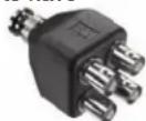
Coax cables are connected together using BNC splitters, available from NVT, or elsewhere. If you purchase BNC "T" connectors from another supplier, please purchase high quality connectors. Low cost connectors have been found to have intermittent shield connections.
UTP and STP wire may be connected to either the BNC or the RJ45, whichever is convenient.
NVT has screw-terminal adaptors available for this purpose. These adaptors support up to four sets of wires, each up to 16AWG.

NV-BNCT
NV-EC4BNC

NV-BNCA

NV-RJ45A
PoE CONSIDERATIONS STREAMING
In PoE parlance, the NV-ET1804 transmitter is known as Power Sourcing Equipment (PSE). It is capable of supporting conventional ethernet, PoE, and PoE+, as well as high power devices up to 50 watts. As such, the NV-ET1804 can support an IP camera that employs an ethernet powered P/T/Z/heater/blower.
Unlike conventional PoE, voltage-drop and load current must be confirmed by the installer. For additional details, see the distance chart on page 7.
NVT's Class 2 current limiting ensures safety of the installation during fault conditions, while delivering higher power with more efficient allocation amongst loads. WARNING: For safety, never use more than two power supplies within a TBus channel. Never exceed 120 watts within a TBus channel. Never use more than one 60 watt remote power supply on each Hub-based TBus channel.
Although NVT transceivers may be connected to PoE-enabled switch ports, they do not use PoE power from the switch, relying instead on their own higher current 56VDC power sources.
NETWORKING CONSIDERATIONS
For IP-based CCTV applications, there are some network configurations that are robust, and others that are not recommended. In general, it is best to deploy a separate LAN exclusively for video traffic. Although it is possible to place IP cameras onto the end-user's "Enterprise LAN", there are several disadvantages in doing so. These include:
Traffic Management Considerations
When sharing the resources of a LAN, the nature of the traffic must be well understood for it to operate efficiently. For most end-users, the business use of their LAN is constantly changing, critical for their day-to-day operations, and not managed by the same group that manages their security. IP video can often consume large amounts of bandwidth, which may or may not be compatible with existing IT traffic.
Security Considerations
Most surveillance systems are installed specifically to protect against breaches in security. A shared LAN provides potential opportunities for unauthorized access to security assets. Sniffing IP addresses can result in the unintended disclosure of IP cameras or network vulnerabilities. Spoofing IP addresses could result in the disruption of recording.
If you must pass IP camera video through "public" LANs, NVT recommends that video be recorded prior to leaving the secure LAN. Then encrypt it by using a Virtual Private Network (VPN) so that neither the video, nor its addressing is readable on the LAN. Many low-cost routers support VPNs.
TOCOL CONSIDERATIONS
Most IP cameras can support multiple video streams using various protocols. MJPEG and H.264 are the most common, and can be transmitted at various rates using unicast (point-to-point) or multicast (single source with multiple destinations).
The NV-ET1804 supports aggregate bandwidths up to 150 Mbps, allowing many devices to operate smoothly on one TBus network. The 150 Mbps bandwidth is dynamically allocated amongst all devices on the TBus network, so care must be taken to not exceed the bandwidth capabilities of the transmission path.
Some protocols, such as TFTP, are particularly ‘chatty’, meaning they generate a lot of acknowledgements that can easily clog a network. NVT recommends simpler protocols for video transmission, such as RTP over UDP.
MULTICAST PACKET SUPPORT

flowchart
graph LR
    A["IP Camera"] -->|Cat5| B["NV-ET1804"]
    C["IP Camera"] -->|Cat5| B
    D["IP Camera"] -->|Cat5| B
    E["IP Camera"] -->|≤328ft (≤100m)| B
    B --> F[" bus any wire "]
    F --> G[" Routing Table"]
    G --> H[" Routing Table"]
    H --> I[" Embedded IGMP Network Querier "]
    I --> J[" Ethernet Switch "]
    J --> K[" IGMP Report "]
    J --> L[" IGMP Query "]
    J --> M[" Firewall "]
    N[" Network Video Recorder "] --> J
    O[" LAN/WAN "] --> P[" Firewall "]
Figure 2 - IGMP Multicast Control
On rare occasions, a customer will experience a problem where a camera sending unicast packets performs flawlessly, but the TBus transceivers “fail” to deliver multicast streams.
Because the TBus devices are delivering data amongst each other in a distributed bus architecture, they need to be told where to send which multicast streams. The TBus transceivers count on the switch(es) to deliver that information.
Sometimes switches have been configured in a way that assumes the TBus transceivers are edge devices (such as PCs or IP cameras). In the interest of saving bandwidth, they do not forward the IGMP control information. Without knowledge of any request for a multicast stream, the TBus transceivers dutifully block that traffic.
Switches and routers (and NVT devices) do not routinely deliver multicast traffic to all destinations. That could overload the network. Instead they rely on a special control protocol to identify and report which recipients (such as the VMS/NVR) are requesting which multicast streams.
That protocol is called Internet Group Management Protocol (IGMP).
How does IGMP Work?
A “Querier” control resource is implemented on one network host, such as a switch or router. Virtually all routers and most switches are equipped with this capability. If there are multiple hosts, the one with the lowest IP address is elected to perform this Querier function.
The Querier is responsible for sending IGMP Queries to the entire network, typically once every three minutes. Any device, such as the VMS/NVR, that wishes to receive a particular
multicast stream responds to this Query by generating an IGMP Report that is sent in the direction of the camera. That Report is monitored and passed on by switches and routers within the network. That monitoring is called IGMP Snooping.
These switches and routers each keep their own Routing Table and use it to determine which ports should and should not receive each multicast stream. It would be inappropriate for the switch to send a multicast stream everywhere, as it would clog the network.
The TBus transceivers are not point-to-point devices. They join together to function as a distributed switch. Like a switch, they listen for IGMP Reports and block unknown multicast packets. This is particularly important in a multi-camera environment, as we do not want the stream from one camera being delivered to all other cameras. That could generate too much traffic.
Switches and routers forward the IGMP Reports on to other switches. However in the interest of not forwarding unnecessary traffic, many switches do not forward these reports to 'Client Ports', such as PCs.
If the TBus transceivers do not receive IGMP Reports, then they will BLOCK UNKNOWN MULTICAST PACKETS, and the multicast video will not pass through.
Solutions
There are several ways to fix this: Running unicast only; Influence the IT department to re-configure the switch; Operate a separate “security” network (recommended); or use the NV-ER1808i or NV-ER1816i Receiver hubs that have their own table-entry list for multicast group addresses.
Contact NVT for more information.
WIRE TYPE AND POWER DISTANCE
The distance capability of wire is dependant on its ability to deliver DC power, and separately, to deliver high-frequency data signals.
The graph below shows maximum power delivery when using a 56V power supply. If you are locally powering your camera (or other remote device), then this graph does not apply. The graph on the next page shows the maximum data delivery rate.
A Distance Calculator can be found at www.nvt.com.
PoE devices require a minimum of 43V to operate. With a 56V supply, we have up to 13V of allowable voltage drop on the wire.
The voltage will dip in proportion to the remote (camera) load. The graph below shows what PoE power distances are supported for various loads and wire types.
- Start with the camera wattage at the left. Sometimes IP cameras are listed as to their PoE Class rather than wattage.
- Now read over to the right until you find your kind of wire. Then look up (feet) or down (meters) to find your maximum distance.
- If your wire is not among the examples, simply measure its total resistance and find the value on the right side of the graph. The maximum supported wattage is on the left.

Figure 3 - Power Distance
Network Video Technologies
(+1) 650.462.8100 • +44 (0) 208 977-6614
nvt.com • info@nvt.com
There are a wide variety of wire qualities, from copper-plated steel at the low end (CATV wire) to high performance low-loss pure copper.
The graph below will help you to determine your data thoughput as a function of wire type and distance.
A Distance Calculator can be found at www.nvt.com.

line
| Maximum Network Data Rate (Mbps) | RG-11 Coax | RG-6 Coax | RG-59 Coax | UTP Cat 5 | Shielded 18/2 | Un-Shielded 18/2 | | -------------------------------- | ---------- | --------- | ---------- | --------- | ------------- | ---------------- | | 0 | 4000 ft | 3000 ft | 2000 ft | 100 ft | 50 ft | 30 ft | | 2040 | 7000 ft | 5000 ft | 3000 ft | 200 ft | 100 ft | 70 ft | | 4080 | 10000 ft | 7000 ft | 4000 ft | 300 ft | 200 ft | 100 ft | | 6160 | 12000 ft | 8000 ft | 5000 ft | 400 ft | 300 ft | 150 ft | | 8320 | 14000 ft | 9000 ft | 6000 ft | 500 ft | 400 ft | 200 ft | | 10540 | 16000 ft | 10000 ft | 7000 ft | 600 ft | 500 ft | 250 ft | | 12880 | 18000 ft | 11000 ft | 8000 ft | 700 ft | 600 ft | 300 ft | | 15240 | 20000 ft | 12000 ft | 9000 ft | 800 ft | 700 ft | 350 ft | | 17680 | 22000 ft | 13000 ft | 10000 ft | 900 ft | 800 ft | 400 ft | | 2016 | 24000 ft | 14000 ft | 11000 ft | 1000 ft | 900 ft | 450 ft | | 2256 | 26000 ft | 15000 ft | 12000 ft | 1100 ft | 1000 ft | 500 ft | | 2512 | 28000 ft | 16000 ft | 13000 ft | 1200 ft | 1100 ft | 550 ft | | 2768 | 30000 ft | 17000 ft | 14000 ft | 1300 ft | 1200 ft | 600 ft | | 3136 | 32000 ft | 18000 ft | 15000 ft | 1400 ft | 1300 ft | 650 ft | | 3412 | 34000 ft | 19000 ft | 16000 ft | 1500 ft | 1400 ft | 75% | | 3684 | 36000 ft | 20000 ft | 17000 ft | 1600 ft | 1500 ft | 85% | | 4 | 38 | - | - | - | - | - | The chart is a line graph with two distinct lines representing different data series. The x-axis represents 'Maximum Network Data Rate (Mbps)' and the y-axis represents 'Typical TBus Wire Distance'. The legend indicates 'RG-11 Coax', 'RG-6 Coax', 'RG-59 Coax', 'UTP Cat 5', 'Shielded 18/2', and 'Un-Shielded 18/2'. The data series are labeled along the curves. The chart is saved as a PNG file named 'typical_tbus_wire_distance.png'.Figure 4 - Data Distance
Network Video Technologies
(+1) 650.462.8100 • +44 (0) 208 977-6614
nvt.com • info@nvt.com
APPLICATION EXAMPLES

flowchart
graph LR
    A["IP Camera"] -->|Cat5| B["NV-ET1804"]
    C["IP Camera"] -->|≤328ft (≤100m)| B
    D["IP Camera"] -->|≤328ft (≤100m)| B
    B --> E["Coax Coax"]
    E --> F["TBus."]
    F --> G["UTP wire"]
    G --> H["NV-ET1801 or NV-ER1804 or NV-ER1808i or NV-ER1816i"]
    H --> I["Cat5 ≤328ft (≤100m)"]
    I --> J["Switch or Router"]
    J --> K["LAN/WAN"]
    J --> L["Hybrid DVR or NVR"]
Figure 5 - Four Cameras

flowchart
graph LR
    A["IP Camera"] -->|Cat5| B["NV-ET1804"]
    C["IP Camera"] -->|any wire| B
    D["IP Camera"] -->|any wire| B
    E["IP Camera"] -->|any wire| B
    F["IP Camera"] -->|≤328ft (≤100m)| G["NV-ET1801"]
    H["IP Camera"] -->|≤328ft (≤100m)| I["NV-ET1801"]
    J["IP Camera"] -->|any wire| K["NV-ET1801 or NV-ER1804 or NV-ER1808i or NV-ER1816i"]
    L["Switch or Router"] -->|Cat5 ≤328ft (≤100m)| M["56VDC Power Supply"]
    N["Hybrid DVR or NVR"] --> O["LAN/WAN"]
    B --> P["TBus. any wire"]
    G --> Q["TBus. any wire"]
    K --> R["TBus. any wire"]
    M --> S["Switch or Router"]
    O --> S
    S --> T["56VDC Power Supply"]
Figure 6 - Multi-Camera Star Topology

flowchart
graph LR
    A["NV-ET1804 NV-ET1804 NV-ET1801"] --> B["IP Camera"]
    A --> C["IP Camera"]
    A --> D["IP Camera"]
    A --> E["IP Camera"]
    A --> F["IP Camera"]
    A --> G["IP Camera"]
    A --> H["IP Camera"]
    A --> I["IP Camera"]
    A --> J["IP Camera"]
    A --> K["IP Camera"]
    A --> L["NV-ET1801"]
    L --> M["TBus. any wire"]
    M --> N["NV-ET1801 or NV-ER1804 or NV-ER1808i or NV-ER1816i"]
    N --> O["Cat5 ≤328ft (≤100m)"]
    N --> P["56VDC Power Supply"]
    P --> Q["Switch or Router"]
    Q --> R["LAN/WAN"]
    R --> S["Hybrid DVR or NVR"]
Figure 7 - Multi-Camera Daisy-Chain Topology
Network Video Technologies
(+1) 650.462.8100 • +44 (0) 208 977-6614
nvt.com • info@nvt.com
MORE APPLICATION EXAMPLES

flowchart
graph LR
    A["IP Camera"] -->|Cat5| B["NV-ET1804"]
    C["IP Camera"] -->|≤328ft (≤100m)| B
    D["IP Camera"] -->|≤328ft (≤100m)| B
    B -->|Coax Coax| E["TBus. UTP wire"]
    E --> F["NV-ET1801 or NV-ER1804 or NV-ER1808i or NV-ER1816i"]
    F --> G["56VDC Power Supply"]
    G --> H["Switch or Router"]
    H --> I["LAN/WAN"]
    I --> J["Hybrid DVR or NVR"]
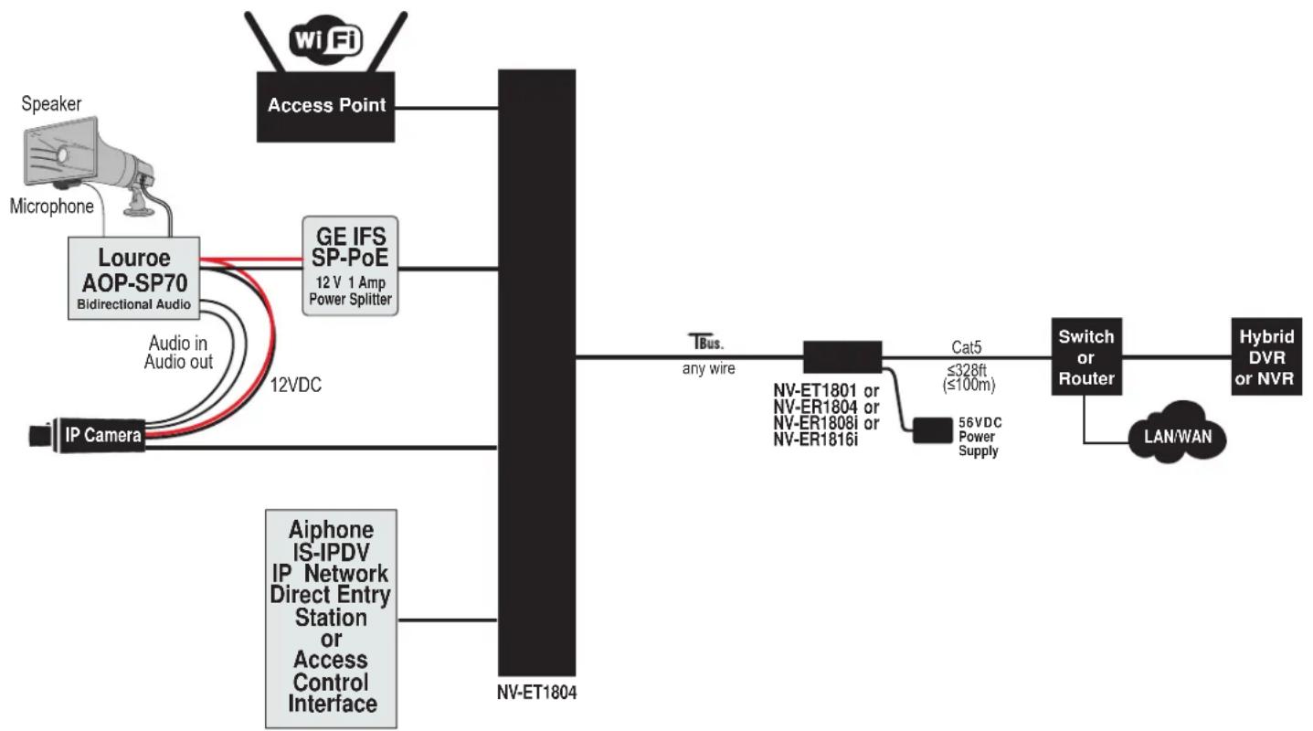
Figure 8 - Mixed Media
flowchart
graph LR
    A["Wi-Fi"] --> B["Access Point"]
    C["Speaker"] --> D["Louroe AOP-SP70 Bidirectional Audio"]
    E["Microphone"] --> D
    D --> F["GE IFS SP-PoE 12 V 1 Amp Power Splitter"]
    G["IP Camera"] --> H["Aiphone IS-IPDV IP Network Direct Entry Station or Access Control Interface"]
    H --> I["NV-ET1804"]
    I --> J["TBus. any wire"]
    J --> K["NV-ET1801 or NV-ER1804 or NV-ER1808i or NV-ER1816i"]
    K --> L["Cat5 ≤328ft (≤100m)"]
    L --> M["Switch or Router"]
    M --> N["Hybrid DVR or NVR"]
    M --> O["LAN/WAN"]
    P["12VDC"] --> H
Figure 9 - Door Entry Devices
Network Video Technologies
(+1) 650.462.8100 • +44 (0) 208 977-6614
nvt.com • info@nvt.com
NV-ET1801 Single port transmitter
NV-ET1804 Four port transmitter
NV-ER1804 Four port receiver
NV-ER1808i Eight port receiver hub
NV-ER1816i Sixteen port receiver hub
NV-PS56-250W Auxiliary 56V 250W Single Power Supply
NV-PS56-250W-2 Auxiliary 56V 250W Dual Power Supply
NV-PS56-250W-3 Auxiliary 56V 250W Triple Power Supply

natural_image
Illustration of three different network switch devices with ports and connectors (no text or symbols visible)


natural_image
Front view of a gray electronic device with ports and indicator lights (no visible text or symbols)

1800 SERIES ACCESSORIES
NV-PS56-60W 56V DC power supply, 60 watts with IEC line cord

natural_image
Black electronic device with two cables and a power plug, no visible text or symbolsNV-PS56-90W 56V DC power supply, 90 watts with IEC line cord

natural_image
Black rectangular electronic device with attached cables and connectors (no visible text or symbols)NV-BNCT BNC "T" adaptor

NV-EC4BNC 1:4 BNC splitter adaptor

NV-BNCA BNC Screw terminal adaptor

NV-RJ45A RJ45 Screw terminal adaptor

NV-PC4PR RJ45 Patch Cord, 4-pair 3' (1m) Grey

TECHNICAL SPECIFICATIONS
RJ45 ETHERNET INTERFACES (4 each)
| Connectivity: | 10/100/1000 BaseT IEEE 802.3ab auto-negotiation, auto MDI / MDX crossover |
| PoE Power: | This Power Sourcing Equipment (PSE) detects and supports Powered Devices (PDs) that are compatible with IEEE 802.3af or 802.3at, or PDs that draw up to 50 watts. For maximum power distance, 56VDC appears on all eight RJ45 pins*. |
| Protection: | Industrial transient protectionThermistor current protection |
| Wire type: | Cat5 or better |
| Distance: | up to 328 feet (100m) |
TBus LINK INTERERFACE
| Connectivity: | BNC or RJ45 |
| Wire type: | Coax, single- or multi-pair UTP, 18/2, or STP wire |
| Impedance: | 25 to 100 Ω |
| Topology: | Bus architecture supports star, daisy-chain, or any combination. One control-room Receiver may support multiple remote TBus Transmitters. |
| Data throughput: | 150 Mbps total network bandwidth* with dynamic bandwidth allocation |
| Latency: | 3 mS |
| Wire distance: | Up to 8,000 feet, 1.5 miles (2.5 Km)* |
| Transmission technology: | IEEE 1901 |
| Wire distance: | Up to 8,000 feet, 1.5 miles (2.5 Km)* |
| Encryption: | 128-bit AES, through one-button Joining |
\*IMPORTANT NOTE:
Data rate, distance, and number of devices may be lower due to wire voltage-drop, power supply capacity, or signal attenuation. See pages 7 & 8.


WARNING:
For safety, never use more than two power supplies within a TBus channel. Never use more than one 60 watt remote power supply on each TBus channel.
REGULATORY
UL Listed to IEC/UL 60950-1
Complies with FCC part 15A limits


WARRANTY
Limited Lifetime
Specifications subject to change without notice.
LED STATUS INDICATORS
| NV-ET1604 Ethernet Transmitter | 50W←→PoE Data 1 PoE Data 2 PoE Data 3 PoE Data 4 PoE TCT100 PoE Network Video Technologies | ||||
| Link | Link Quality | Data | PoEPowe | ||
| Flashes when initializing or Joining | Remote device detected | Green = good Amber = fair Red = poor | Green = good Flashes with Data | Green = PoE device connected | |
MECHANICAL / ENVIRONMENTAL
| Body Dimensions: | 6.00 in (152 mm) wide1.39 in (35 mm) high4.40 in (112 mm) deepexcluding connectors |
| Shipping weight: | 1.20 lb (0.54 Kg) |
| Operating / storage temperature: | -40°F to 185°F (-40°C to +85°C)20 to 85% relative humiditynon-condensing |
| Power consumption: | ≤3W |
| Generated heat: | 10 BTU/hour |
| Transient immunity: | 5 x 20μS 3,000A, 6,000VESD 20KV, 200pF |
POWER SUPPLY
Power is usually supplied by the TBus Receiver. For optional supplemental local power, an additional class 2 power supply may be purchased. These supplies are external inline, with an IEC380-C14 power inlet and a 6 ft (1.18 m) line cord. Input voltage is 100\~240VAC 50/60Hz. A molded P1J 5.5mm barrel connector provides a class 2 (SELV) regulated output.
| Model NV-PS56-60W: | 56V 60W |
| 4.90 in (124 mm) long | |
| 2.00 in (51 mm) wide | |
| 1.25 in (32 mm) high, 0.67 lbs (300 g) |
| Model NV-PS56-90W: | 56V 90W |
| 5.77 in (147 mm) long | |
| 2.36 in (60 mm) wide | |
| 1.27 in (32 mm) high, 0.94 lb (430 g) |
| Operating / storage temperature: | -40°F to +185°F (-40°C to +85°C)20 to 5% relative humiditynon-condensing |
| Transient Immunity: | 5x20μS 3000A, 6000VESD 20KV, 200pF |
Use only the power cord provided with the unit or equivalent UL approved type SPT-2, SVT, or SJT 18/3 AWG 100\~240 VAC, 1 Amp 60°C max 15 ft (4.5 m) long. One end with IEC380-C13 appliance coupler and the other end with NEMA 1015P or equivalent for your country.
TROUBLESHOOTING
Confirm that the NVT transceivers have been configured to communicate with each other, per instructions on page 3.
If you are experiencing problems, attempt to simplify your setup. Test each cable segment separately. For example, test a simpler configuration first. Then add in the NVT transceivers, back-to-back. Test each segment of a long cable-run independently. Attempt to isolate the problem.
Most IP camera installation problems involve configuring the IP camera and the recorder to recognize each other. If in doubt, connect the camera directly to the Ethernet switch, bypassing the transceivers. Consult the IP camera and/or recorder installation manuals for configuration instructions, or contact the camera or recorder manufacturer.
Which camera and NVT LEDs are on?
Can you ping the camera?
Test if unicast traffic passes smoothly but multicast traffic is blocked. (See page 6.)
NETWORK DIAGNOSTIC TOOLS
NVT has developed a Console Utility that can be downloaded from www.nvt.com. Once installed on any Windows PC, the applicationscours the network for NVT devices, and reports each of their MAC addresses, as well as the MAC addresses of any other NVT devices within its joined group.
Additional network tools, such as Packet Sniffers or Traffic generators are available from other sources such as LAN Shark, LANTraffic, etc.
CUSTOMER SUPPORT
NVT customer support is available for consultation from 8:00 AM to 5:30 PM PST Monday through Friday. In addition, emergency after-hours callback support is available.
USA Office: (+1) (650) 462-8100
USA Fax: (+1) (650) 326-1940
UK Office: (+44) (0)20 8977 6614
UK Fax: (+44) (0)20 8973 1855
Email USA: www.nvt.com/email/info
Email UK: www.nvt.com/email/eusales
Web home page: www.nvt.com
PRODUCT RETURNS
Please call before returning units to NVT. Returned materials must have a “Returned Materials Authorization” (RMA) number from NVT marked on the outside of the shipping carton.
LIMITED LIFETIME WARRANTY
NVT warrants that the product conforms to NVT's applicable published specifications and is free of defects for the life of the product. There shall be no other warranties, express, statutory, or otherwise, including any implied warranty of merchantability, of fitness, or any other obligation on the part of NVT with respect to any of the products. In the event that any of the products is damaged, altered, or modified without the express written consent of NVT, any warranty for those products will cease and NVT will have no further liability as it pertains to those products.
NVT assumes no responsibility for damages or penalties incurred resulting from the use of this product in a manner or location other than for which it is intended.
NVT's liability under any warranties shall be discharged by replacing or repairing any part or parts which do not conform to the applicable warranty under normal and proper use. NVT's liability with respect to any product shall not exceed a refund of the price received by NVT for that product, and in no event shall NVT have any liability for any incidental, consequential, special, or indirect damages.
Some states do not allow the exclusion or limitation of special, incidental, or consequential damages, so the above limitations or exclusions may not apply to you. This warranty gives you specific legal rights, and you may also have other rights which vary from state to state.
FCC USER INFORMATION
This equipment has been tested and found to comply with the limits for a Class B digital device, pursuant to part 15 of the FCC Rules. These limits are designed to provide reasonable protection against harmful interference in a residential installation. This equipment generates, uses, and can radiate radio frequency energy and, if not installed and used in accordance with the instructions, may cause harmful interference to radio communications. However, there is no guarantee that interference will not occur in a particular installation. If this equipment does cause harmful interference to radio or television reception, which can be determined by turning the equipment off and on, the user is encouraged to try to correct the interference by one or more of the following measures:
- Reorient or relocate the receiving antenna.
- Increase the separation between the equipment and the receiver.
- Connect the equipment into an outlet on a circuit different from that to which the receiver is connected.
- Consult the dealer or an experienced radio/TV technician for help.
WARNING
Changes or modifications not expressly approved by the manufacturer could void the user's authority to operate the equipment.
- IMPORTANT SAFETY INSTRUCTIONS
- Four Port PoE+ Transmitter Model NV-ET1804
- CONFIGURATION INSTRUCTIONS
- Step One: Gather Materials
- Step Two: Connect Hardware
- Step Three: Joining
- Step Four: Adding Transceivers (if required)
- Step Five: Documentation
- Un-Joining a Transceiver
- INSTALLATION INSTRUCTIONS
- Transceiver Configuration
- Connecting the Camera End
- Connecting the Control-Room End
- If your receiver is an NV-ET1801 or NV-ER1804, and the blue LEDs continues to blink, check the power supply's LED. If it is cycling on and off then there is an overload condition. Check for wire faults (including polarity) or excessive loading.
- Verify Camera End LEDs
- BUS ARCHITECTURE
- PoE CONSIDERATIONS STREAMING
- NETWORKING CONSIDERATIONS
- Traffic Management Considerations
- Security Considerations
- TOCOL CONSIDERATIONS
- MULTICAST PACKET SUPPORT
- How does IGMP Work?
- If the TBus transceivers do not receive IGMP Reports, then they will BLOCK UNKNOWN MULTICAST PACKETS, and the multicast video will not pass through.
- Solutions
- WIRE TYPE AND POWER DISTANCE
- A Distance Calculator can be found at www.nvt.com.
- Network Video Technologies
- APPLICATION EXAMPLES
- MORE APPLICATION EXAMPLES
- SERIES ACCESSORIES
- TECHNICAL SPECIFICATIONS
- \*IMPORTANT NOTE:
- WARNING:
- REGULATORY
- WARRANTY
- POWER SUPPLY
- TROUBLESHOOTING
- NETWORK DIAGNOSTIC TOOLS
- CUSTOMER SUPPORT
- PRODUCT RETURNS
- LIMITED LIFETIME WARRANTY
- FCC USER INFORMATION
- WARNING
Brand : Phybridge
Model : NV-ET1804
Category : Wi-Fi Router