RE3-RX5L - Microphone ELECTRO-VOICE - Free user manual and instructions
Find the device manual for free RE3-RX5L ELECTRO-VOICE in PDF.

User questions about RE3-RX5L ELECTRO-VOICE
0 question about this device. Answer the ones you know or ask your own.
Ask a new question about this device
Download the instructions for your Microphone in PDF format for free! Find your manual RE3-RX5L - ELECTRO-VOICE and take your electronic device back in hand. On this page are published all the documents necessary for the use of your device. RE3-RX5L by ELECTRO-VOICE.
USER MANUAL RE3-RX5L ELECTRO-VOICE
1 Safety, precautions, and notices 4
1.1 Important safety instructions 4
1.2 Battery precautions 5
1.3 Notices 5
1.4 Licensing, certifications, restrictions and manufacturers declarations 6
2 Short information 10
2.1 Shipping contents 11
3 Description 13
4 Glossary of terms 15
5 Best practices for successful operation 17
6 Quick setup 19
6.1 Preparing the receiver 19
6.2 Preparing the transmitter 19
6.3 Sync the transmitter to the receiver 19
6.4 Ensure transmitter input sensitivity is set for best signal level 20
7 RE3-RX receiver 21
7.1 Product identification 21
7.2 LCD display 24
7.3 RE3-RX setup menu 25
8 RE3-HHT handheld transmitter 40
8.1 Product identification 40
8.2 LCD display 42
8.3 Installing batteries 43
8.4 RE3-HHT setup menu 43
9 RE3-BPT bodypack transmitter 47
9.1 Product identification 47
9.2 LCD display 49
9.3 Installing batteries 50
9.4 RE3-BPT Setup Menu 50
10 Accessories for RE3 54
11 Troubleshooting and FAQ 56
11.1 Troubleshooting 56
11.2 Frequently Asked Questions 62
12 Technical data 67
13 Frequency Group / Channel Tables 77
1 Safety, precautions, and notices
1.1 Important safety instructions

WARNING: TO REDUCE THE RISK OF FIRE OR ELECTRIC SHOCK, DO NOT OVEREXPOSE THIS APPLIANCE TO RAIN OR MOISTURE
AVIS: RISQUE DE CHOC ELECTRIQUE, NE PAS OUVRIR.
WARNING: THE MAINS PLUG OR DC INLET IS USED AS A DISCONNECT DEVICE. THE DISCONNECT DEVICE SHALL REMAIN READILY OPERABLE.
WARNING: CONNECT ONLY TO MAINS SOCKET WITH PROTECTIVE EARTHING CONNECTION.
WARNING: TO REDUCE THE RISK OF ELECTRIC SHOCK, DO NOT REMOVE COVER (OR BACK) AS THERE ARE NO USER-SERVICABLE PARTS INSIDE. REFER SERVICING TO QUALIFIED PERSONNEL.

The exclamation point within an equilateral triangle is intended to alert the user to the presence of important operating and maintenance (servicing) instructions in the literature accompanying the appliance.
- Read these instructions.
- Keep these instructions.
- Heed all warnings.
- Follow all instructions.
- Do not use this apparatus near water.
- Clean only with a dry cloth.
- Do not block any ventilation openings. Install in accordance with the manufacturer's instructions.
- Do not install near any heat sources such as radiators, heat registers, stoves, or other apparatus (including amplifiers) that produce heat.
- Do not defeat the safety purpose of the polarized or grounding-type plug where present. A polarized plug has two blades with one wider than the other. A grounding type plug has two blades and a third grounding prong. The wide blade or the third prong is provided for your safety. If the provided plug does not fit into your outlet, consult an electrician for replacement of the obsolete outlet.
-
Protect the power cord from being walked on or pinched particularly at plugs, convenience receptacles, and the point where they exit from the apparatus.
-
Only use attachments/accessories specified by the manufacturer.
- Unplug the apparatus during lightning storms or when unused for long periods of time.
- Refer all servicing to qualified service personnel. Servicing is required when the apparatus has been damaged in any way, such as power-supply cord or plug is damaged, liquid has been spilled or objects have fallen into the apparatus, the apparatus has been exposed to rain or moisture, does not operate normally, or has been dropped.
- No naked flame sources, such as lighted candles, should be placed on the apparatus.
- To reduce the risk of fire or electric shock, do not expose this apparatus to rain or moisture. The apparatus should not be exposed to dripping or splashing. Objects filled with liquids, such as vases or open beverage containers should not be placed on apparatus.
- To completely disconnect DC power from this apparatus, the DC power supply cord must be unplugged from the apparatus, or the apparatus' external power supply must be unplugged from the AC socket.
- To completely disconnect AC power from this apparatus' external power supply, the power supply plug must be unplugged at the AC socket.
1.2 Battery precautions

Keep batteries out of the reach of children.
Observe and install batteries according to the correct polarity as marked on the battery and the transmitter battery compartment.
Do not expose the battery to excessive heat such as sunshine, fire, or other sources of high heat.
Always consider the environment issues and follow local regulations when disposing of batteries.
Remove depleted battery immediately.
Danger of explosion if battery is incorrectly replaced. Replace only with the same or equivalent type.
Use only disposable LR6(AA) alkaline or NiMH batteries.
Do not mix new batteries with old ones in the transmitter at the same time.
Do not use different battery types or models.
Do not use a leaking battery. If battery leakage occurs, avoid contact with skin. If contact occurs, immediately wash thoroughly with soap and water.
If battery leakage comes into contact with your eyes, immediately flush with water and seek medical attention.
Remove and safely store batteries away from the transmitter when the transmitter will not be used for 60 or more days.
1.3 Notices

Old electrical and electronic appliances
Electrical or electronic devices that are no longer serviceable must be collected separately and sent for environmentally compatible recycling (in accordance with the European Waste Electrical and Electronic Equipment Directive). To dispose of old electrical or electronic devices, you should use the return and collection systems put in place in the country concerned.
Copyright and disclaimer
All rights reserved. No part of this document may be reproduced or transmitted in any form by any means, electronic, mechanical, photocopying, recording, or otherwise, without the prior written permission of the publisher. For information on getting permission for reprints and excerpts, contact Electro-Voice. All content including specifications, data, and illustrations in this manual are subject to change without prior notice.
1.4 Licensing, certifications, restrictions and manufacturers declarations
Regarding handheld transmitters RE3-HHT-5L (480-524 MHz), RE3-HHT-5H (560-596 MHz), RE3-HHT-6M (653-663 MHz), and bodypack transmitters RE3-BPT-5L (480-524 MHz), RE3-BPT-5H (560-596 MHz), and RE3-BPT-6M (653-663 MHz):
1.4.1 FCC information
Certified under FCC Part 15 and FCC Part 74.
FCC ID: B5DH2285L, B5DH2285H, B5DH2286M, B5DB1245L, B5DB1245H, B5DB1246M.

NOTE: Regarding RE3-HHT-6M (653-663 MHz) and RE3-BPT-6M (653-663 MHz); use of frequencies beginning at 653.000 MHz up to 657.000 MHz is covered under FCC Part 74 ID numbers B5DH2286M and B5DB1246M, and require an LPAS user license, however use of frequencies between 657.025 up to 663.000 MHz is covered under FCC Part 15, and do not require an additional user license. For more information, see https://www.fcc.gov/consumers/guides/operation-wireless-microphones.
FCC Supplier's Declaration of Conformity
47 CFR, Section 2.1077 Compliance Information
Product Identifier:
Electro-Voice:
RE3 Wireless Receiver, AASP Active Antenna Splitter, ALPA
Active Log Periodic Antenna, RFAMP Antenna Booster, BC2
Battery Charger
Responsible Party – U.S. Contact Information
Bosch Security Systems, Inc.
130 Perinton Parkway
Fairport, NY 14450
USA
Tel: +1 (585) 223-4060
FCC Compliance Statement
This device complies with Part 15 of the FCC Rules. Operation is
subject to the following two conditions: (1) This device may not be
CAUTION: Changes or modification made by the user could void the user's authority to operate the equipment.
This equipment has been tested and found to comply with the limits for a Class B digital device, pursuant to Part 15 of the FCC Rules. These limits are designed to provide reasonable protection against harmful interference in a residential installation. This equipment generates, uses, and can radiate radio frequency energy and, if not installed and used in accordance with the instructions, may cause harmful interference to radio communications. However, there is no guarantee that interference will not occur in a particular installation. If this equipment does cause harmful interference to radio or television reception, which can be determined by turning the equipment off and on, the user is encouraged to try to correct the interference by one or more of the following measures:
■ Reorient or relocate the receiving antenna.
- Increase the separation between the equipment and the receiver.
- Connect the equipment to an outlet on a circuit different from that to which the receiver is connected.
- Consult the dealer or an experienced radio/TV technician for help.
1.4.2 IC (Industry Canada)
Certified in Canada by IC under RSS-102, and RSS-210, and RSS-Gen
IC: 1321A-RE3HHT488, 1321A-RE3HHT560, 1321A-RE3HHT653, 1321A-RE3BPT488, 1321A-RE3BPT560, 1321A-RE3BPT653.
This device complies with Industry Canada license-exempt RSS standard(s). Operation is subject to the following two conditions:
(1) This device may not cause interference, and
(2) This device must accept any interference, including interference that may cause undesired operation of the device.
NOTE: Regarding RE3-HHT-6M (653-663 MHz) and RE3-BPT-6M (653-663 MHz); the use of frequencies between 653.025 up to 663.000 MHz, please check the Canada's ISED
(Innovation, Science and Economic Development) website for the current information of the license status of this band.
1.4.3 Licensing information
Licensing: A ministerial license to operate this equipment may be required in certain areas.
Consult your national authority for possible requirements. Changes or modifications not expressly approved by Electro-Voice could void your authority to operate the equipment.
Licensing of Electro-Voice wireless microphone equipment is the user's responsibility, and licensability depends on the user's classification and application, and upon the selected frequencies on which it will operate. Electro-Voice advises the user to contact the appropriate telecommunications authority concerning proper licensing, and before selecting and ordering frequency bands.
1.4.4 EU (European Union)
The CE Declaration of Conformity can be obtained and downloaded from: www.electrovoice.com
This Equipment is in compliance with the following directives:
■ 2011/65/EU RoHS Directive
■ 2012/19/EU WEEE Directive
■ 2014/53/EU RED Directive
Regarding (applies to) handheld transmitter RE3-HHT-5L (480-524 MHz), RE3-HHT-5H (560-596 MHz), RE3-HHT-6M (653-663 MHz), RE3-HHT-8M (823-865 MHz), and bodypack transmitter RE3-BPT-5L (480-524 MHz), RE3-BPT-5H (560-596 MHz), RE3-BPT-6M (653-663 MHz), and RE3-BPT-8M (823-865 MHz):
This equipment is intended for use in wireless microphone applications.
Some countries in the EEA (European Economic Area) have restrictions placed on this equipment. If an EEA country is not listed it did not have any restrictions of the product at the time this document was published.
The country codes used in regard to these restrictions are the following:
Austria (AT), Belgium (BE), Cyprus (CY), Denmark (DK), Germany (DE), Greece (EL), Spain (ES), Ireland (IE), Iceland (IS), Latvia (LV), Lithuania (LT), Malta (MT), Norway (NO), Slovakia (SK), Sweden (SE) and United Kingdom (UK).
Listed below are these restrictions:
- Transmitters in the ranges, 488 – 524 MHz, 560 – 596 MHz and 653 – 663 MHz, require a license in the following countries: AT, BE, CY, DE, IE, LV, LT, SK, SE, UK.
- Transmitters in the ranges, 488 – 524 MHz, 560 – 596 MHz and 653 – 663 MHz, require the transmitter be used in TV white spaces: AT, DK, IS, MT, NO, ES.
- Transmitters in the ranges, 488 – 524 MHz, 560 – 596 MHz and 653 – 663 MHz, if used outdoor will have geographical restrictions of operation in the United Kingdom (UK)
- Transmitters in the range, 823 – 865, require a license for use in the 823 – 832 MHz range in the following countries: AT, BE, CY, EL, IE, LV, LT, UK.
- Transmitters in the range, 488 – 524 MHz, may only use the range 510 – 524 MHz in Norway (NO).
Note: TV white spaces are gaps between operating TV broadcast stations where there are no active TV broadcasts.
Always consult your national authority before placing equipment into operation as requirements and spectrum usage can change.
1.4.5 AU and NZ
This device operates under an ACMA class license and must comply with all the terms of that license including operating frequencies.
2 Short information
The following table lists products in a family, with CTN (Commercial Type Number) and identifying product name DESCRIPTION.
| CTN | DESCRIPTION |
| RE3-ND76-5L | Handheld set with ND76 head 488-524MHz |
| RE3-ND76-5H | Handheld set with ND76 head 560-596MHz |
| RE3-ND76-6M | Handheld set with ND76 head 653-663MHz |
| RE3-ND76-8M | Handheld set with ND76 head 823-865MHz |
| RE3-ND76-T | Handheld set with ND76 head 803-806MHz |
| RE3-ND86-5L | Handheld set with ND86 head 488-524MHz |
| RE3-ND86-5H | Handheld set with ND86 head 560-596MHz |
| RE3-ND86-6M | Handheld set with ND86 head 653-663MHz |
| RE3-ND86-8M | Handheld set with ND86 head 823-865MHz |
| RE3-ND86-T | Handheld set with ND86 head 803-806MHz |
| RE3-ND96-5L | Handheld set with ND96 head 488-524MHz |
| RE3-ND96-5H | Handheld set with ND96 head 560-596MHz |
| RE3-ND96-6M | Handheld set with ND96 head 653-663MHz |
| RE3-ND96-8M | Handheld set with ND96 head 823-865MHz |
| RE3-ND96-T | Handheld set with ND96 head 803-806MHz |
| RE3-RE420-5L | Handheld set with RE420 head 488-524MHz |
| RE3-RE420-5H | Handheld set with RE420 head 560-596MHz |
| RE3-RE420-6M | Handheld set with RE420 head 653-663MHz |
| RE3-RE420-8M | Handheld set with RE420 head 823-865MHz |
| RE3-RE420-T | Handheld set with RE420 head 803-806MHz |
| RE3-RE520-5L | Handheld set with RE520 head 488-524MHz |
| RE3-RE520-5H | Handheld set with RE520 head 560-596MHz |
| RE3-RE520-6M | Handheld set with RE520 head 653-663MHz |
| RE3-RE520-8M | Handheld set with RE520 head 823-865MHz |
| RE3-RE520-T | Handheld set with RE520 head 803-806MHz |
| RE3-BPOL-5L | Bodypack set, omni lavalier 488-524MHz |
| RE3-BPOL-5H | Bodypack set, omni lavalier 560-596MHz |
| RE3-BPOL-6M | Bodypack set, omni lavalier 653-663MHz |
| RE3-BPOL-8M | Bodypack set, omni lavalier 823-865MHz |
| RE3-BPOL-T | Bodypack set, omni lavalier 803-806MHz |
| RE3-BPCL-5L | Bodypack set, cardioid mic 488-524MHz |
| RE3-BPCL-5H | Bodypack set, cardioid mic 560-596MHz |
| RE3-BPCL-6M | Bodypack set, cardioid mic 653-663MHz |
| RE3-BPCL-8M | Bodypack set, cardioid mic 823-865MHz |
| RE3-BPCL-T | Bodypack set, cardioid mic 803-806MHz |
| RE3-BPHW-5L | Bodypack set, headworn mic 488-524MHz |
| RE3-BPHW-5H | Bodypack set, headworn mic 560-596MHz |
| RE3-BPHW-6M | Bodypack set, headworn mic 653-663MHz |
| RE3-BPHW-8M | Bodypack set, headworn mic 823-865MHz |
| RE3-BPHW-T | Bodypack set, headworn mic 803-806MHz |
| RE3-BPGC-5L | Bodypack instrument set 488-524MHz |
| RE3-BPGC-5H | Bodypack instrument set 560-596MHz |
| RE3-BPGC-6M | Bodypack instrument set 653-663MHz |
| RE3-BPGC-8M | Bodypack instrument set 823-865MHz |
| RE3-BPGC-T | Bodypack instrument set 803-806MHz |
| RE3-BPNID-5L | Bodypack set, no input device 488-524MHz |
| RE3-BPNID-5H | Bodypack set, no input device 560-596MHz |
| RE3-BPNID-6M | Bodypack set, no input device 653-663MHz |
| RE3-BPNID-8M | Bodypack set, no input device 823-865MHz |
| RE3-BPNID-T | Bodypack set, no input device 803-806MHz |
2.1 Shipping contents
This manual is packaged in a preconfigured set containing a receiver and its supplied accessories, as well as a transmitter and its supplied accessories. The delivered set configurations vary.
2.1.1 Items contained in all sets
| Quantity | Component |
| 1 | Receiver |
| 2 | Receiver antennas |
| 1 | Receiver power supply with four power convention specific AC plug clips |
| 2 | Rack-mount brackets |
| 2 | Rack-mount bracket hole filler plugs |
| 1 | Pack of four (4) screws to mount rack brackets |
| 1 | Safety booklet |
| 1 | Installation manual |
2.1.2 Set variants (based upon configuration ordered)
Handheld sets (RE3-ND76, RE3-ND86, RE3-ND96, RE3-RE420, and RE3-RE520)
| Quantity | Component |
| 1 | Handheld transmitter body |
| 1 | Handheld transmitter stand adapter |
| 2 | AA alkaline batteries |
| 1 | Microphone headBased on the set configuration, the package will contain one (1) microphone head from the following list:RE3-ND76 contains 1 ND76-RC3 thread-on head and data sheetRE3-ND86 contains 1 ND86-RC3 thread-on head and data sheetRE3-ND96 contains 1 ND96-RC3 thread-on head and data sheetRE3-RE420 contains 1 RE420-RC3 thread-on head and data sheetRE3-RE520 contains 1 RE520-RC3 thread-on head and data sheet |
Bodypack sets (RE3-BPOL, RE3-BPCL, RE3-BPHW, RE3-BPGC, and RE3-BPNID)
| Quantity | Component |
| 1 | Bodypack transmitter |
| 2 | AA alkaline batteries |
| 1 | Input deviceBased on the set configuration, the package will contain one input device from the following list:RE3-BPOL contains 1 RE3-ACC-OL3 omnidirectional lavalier microphone, clip, windscreen, and data sheetRE3-BPCL contains 1 RE3-ACC-CL3 cardioid lavalier microphone clip, windscreen, and data sheetRE3-BPHW contains 1 RE3-ACC-HW3 cardioid headworn microphone, windscreen, and data sheetRE3-BPGC contains 1 RE3-ACC-GC3 instrument cable with 14 " plug and data sheet |
NOTE: RE3-BPNID does not contain an input device.
3 Description
Thank you for choosing an Electro-Voice wireless microphone product. Please take time to consult this manual to understand all the features and functions built into your Electro-Voice wireless set and fully utilize its performance capabilities.
RE3 is a range of RF wireless microphone products operating in the UHF portion of the radio spectrum. The use of this portion of the radio spectrum falls under local government regulations which may require the user to obtain and maintain a license to operate the wireless product. It is the user's responsibility to know and adhere to local license requirements.
Primary products, such as receivers and transmitters, are preconfigured into sets covering a wide variety of common applications, making them ideal performance and presentation solutions for both portable productions, as well as fixed installation applications. All sets contain one 12 rack space receiver with antennas, power supply and rack mount, one transmitter with batteries and its input device (as applicable), as well as user documentation sheets.
Additionally, the RE3 extended portfolio contains an extensive assortment of optional accessories to aid in the creation of large, multi-channel, professional-application systems. For a full list of available accessories, see Accessories for RE3, page 48 of this manual.
Set features
- Rack mountable 12 space receiver with mounting hardware
- Robust metal handheld and bodypack transmitter bodies
■ Easy-to-read LDC displays
■ Frequency scanning for selecting open frequencies
■ Sync function links transmitter to receiver
■ Keylock function protects settings from unwanted changes
■ Diversity reception technology for trouble-free operation - Broad selection of transmitter microphone types maximize application diversity
-
Wide selection of tuning bandwidths to help compensate for changing global RF regulations
■ Frequencies independently adjustable in 25kHz steps -
Eight groups of pre-coordinated frequencies with up to 22 coordinated channels per group
■ Simple multi-channel system setup
■ Transmitters powered by common AA cells - Selectable hi and low transmitter power in most global regions.
- Extensive selection of optional system accessories available
See also
Technical data, page 58
Frequency Group / Channel Tables, page 67
4 Glossary of terms
| Term | Definition |
| System vs set | Because the terms system and set can be used interchangeably, thereby causing confusion, this manual refers to a set as a single mated pair of one transmitter and one receiver. Whereas a system is the collection of multiple wireless sets and antenna distribution items. |
| Set | A pre-packaged combination of receiver, receiver antenna, receiver power supply, transmitter, transmitter input device, and other supplied accessories. For example, if you purchased an RE3-ND76-5L, the manufacturer considers it a set. Also it is the basic hardware combination of a mated transmitter and receiver. |
| SET | A multi-purpose menu navigation key which functions as an enter key, a menu advance key, an item select key, and a save or store key. |
| Scroll | To navigate up and down menus or item options using the ▲ and ▼ buttons. |
| Group | A predefined combination of intermodulation-free frequencies. |
| Channel | As it relates to frequencies within a group, it is the exact frequency a set can be tuned to.As it relates to a multi-channel system, it is the quantity of unique paired transmitters and receivers. For example, a multi-channel system consisting of eight receivers and eight mated transmitters is said to be an eight channel system. |
| Intermodulation | The adverse reception interference that occurs when two or more non-coordinated frequencies produce harmonics which disrupt reception of one or more channels. |
| SYNC | The operation of synchronizing a receiver's transmitter data to the mated transmitter. |
| RX | Abbreviation for receiver. |
| TX | Abbreviation for transmitter. |
| RF | Abbreviation for radio frequency. RE3 is an RF wireless microphone set operating in the UHF radio spectrum. |
| UHF | Abbreviation for ultra-high frequency, and is the term when applied to wireless microphone products as the portion of radio spectrum shared with UHF television signals between 470MHz and 865MHz. Those limits vary by country where used. |
| MHz | Abbreviation for megahertz denoting frequencies measuring in the millions of cycles per second. A common reference for wireless microphones using this shortened numerical expression could be |
| 652.725MHz (six-hundred fifty-two million, seven hundred twenty-five thousand cycles per second). | |
| Multi-channel system | A system made up of two or more sets where each set is tuned to a specific frequency (channel) which does not interfere with the operation of other member sets within the system. A multi-channel system can be made up of sets all from the same frequency band, or sets from multiple frequency bands.When using multiple sets operating in the same frequency band, each set must be operating on a frequency-coordinated channel within the same group. |
5 Best practices for successful operation
- Never attempt to operate two or more transmitters on the same frequency at the same time. While multiple receivers can successfully tune to a single transmitted frequency, multiple transmitters simultaneously operating on the same frequency will immediately interfere with each other. If a goal is to create a combo system by adding an optional transmitter (one bodypack transmitter and one handheld transmitter to work with one receiver), only one of those transmitters can be on and tuned to the receiver at a time.
- Ensure the receiver's antennas are properly attached, exposed (not buried within a rack) and oriented as suggested in the Preparing the receiver section, page 17.
- Scan for open frequencies first with transmitter off. The receiver antennas must be properly connected for best scan results.
- When scanning and synchronizing a multi-channel system, scan and synchronize one system at a time. To begin, have all transmitters off and scan system receiver 1 first. Then turn on system transmitter 1 and sync it to receiver 1. Leaving system transmitter 1 on, move on to receiver 2. With system transmitter 1 on, scan system receiver 2 and tune it to the next open frequency within the same group as system 1. Turn on system transmitter 2 and sync it to system receiver 2. Then leave system transmitter 2 on. Follow this process while scanning and syncing all channels within a multi-channel system.
- Always have all member sets of a multi-channel system within the same frequency band operating in the same frequency group. Mixing frequencies (channels) from different groups within the same frequency band is not recommended. Channels within a group are intermodulation-free. Simultaneous operation of channels from different groups may lead to intermodulation interference.
- If desired, use the receiver's mic configuration menu items to set transmitter operating parameters prior to syncing the transmitter to the receiver. If a receiver's mic configuration is changed since the last transmitter sync, resync the transmitter to update its parameter settings.
- Properly setting transmitter sensitivity is key to optimum performance. Best practice: While observing the receiver's AF meter activity, adjust the transmitter sensitivity so that high vocal peaks light the yellow LED segment. Under extremely loud vocal peaks, an occasional red LED segment light is OK, but a solid and constant red LED should be avoided.
- Choosing transmitter low or high power: The transmitter in your set may have two output power setting options (8M band has only one). The higher setting may not be appropriate for your application as it is possible that high may be too high based on the
distance between the transmitter and receiver antennas, or other systems within close proximity in a multi-channel system. Low is likely to be sufficient when the set is in a small to medium size room or space. High may be the best choice for large rooms or spaces where the distance between transmitter and receiver antennas is substantial or existing RF conditions limit the range between transmitter and receiver. Simple performance tests will help identify best settings, and having two output power options will aid in successful operation.
- A large multi-channel system can be made up of sets operating in different frequency bands. This is a good method to follow when maximizing a high channel count system potential. Based on RF conditions in the operating vicinity, select appropriate numbers of sets from available bands in your country to achieve a desired high channel count system.
6 Quick setup
6.1 Preparing the receiver
a. Remove the receiver, packaged power supply kit and two antennas from the product carton.
b. Place the receiver either on a stable flat surface or in a 19" rack using the rack kit supplied.
c. Locate the power supply and attach the supplied AC wall outlet clip which is appropriate for your country's mains power by sliding it into the power supply head, and plug the DC power lead end of the cable into the receiver DC input jack.
d. Locate, unwrap, and attach the two supplied receiver antennas by inserting them onto the receiver's BNC antenna jacks and locking them into place by applying a right-hand twist. Take special care to ensure the receiver antennas are exposed to open air, not touching any items that would ground them, and oriented 90 degrees to one another and positioned at 45 degrees relative to the floor.
e. Turn on the receiver by pressing the power button.
f. Ensure the transmitter for this set is turned off.
g. Press the scan button and follow the scanning instructions described in Scanning for open channels, page 24.
h. After the scan is complete, select the group and channel from the results list which best matches your system needs.
i. Follow the scanning instructions in Scanning for open channels, page 24 to return the receiver's display to the home screen.
j. Leave the receiver on until the desired mating transmitter has been prepared and synced.
6.2 Preparing the transmitter
a. Remove the transmitter, batteries, and input device (if supplied) from the product carton.
b. Insert the batteries into the transmitter paying close attention to the battery polarity (+ and -) and matching those polarities to the + and - poles of the battery compartment battery clips.
c. Connect the transmitter's input device to the transmitter (a bodypack set will contain either a lavalier microphone, headworn microphone, or instrument cable – a handheld set will contain a thread-on microphone head.
d. Turn on the transmitter by pressing the power button.
6.3 Sync the transmitter to the receiver
a. Locate the transmitter's sync port and the receiver's sync emitter which are both identified with the (●) symbol.
b. Maintaining direct line of sight and a separation distance of two to twelve inches between the transmitter and receiver ports.
c. Directly aim the transmitter sync port at the receiver sync emitter.
d. Press the sync button on the front of the receiver to begin the syncing process (green LED flashes on receiver).
e. Hold the transmitter in place until the sync process is complete. Upon successful sync the transmitter will be tuned to the receiver and ready for use.
6.4 Ensure transmitter input sensitivity is set for best signal level
a. While viewing receiver AF meter activity, perform as you would in a normal performance using proper microphone placement.
b. Observe the AF meter LED segments. Ideal level should show all green LEDs and the yellow LED lit on emphasis peaks. An occasional red LED is OK, but a constant, solid red LED should be avoided.
c. Adjust transmitter input sensitivity until item b above is achieved.
Upon successful completion of this section, your set is ready for operation.
7 RE3-RX receiver
7.1 Product identification
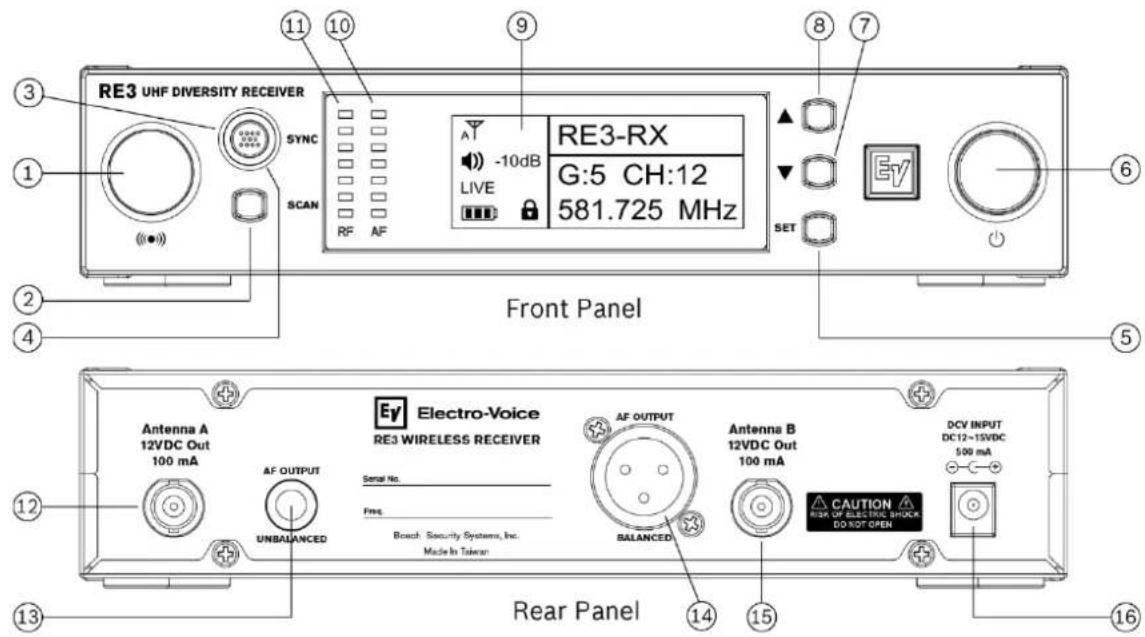
| ID | Item | Description, usage and notes |
| 1 | Sync signal emitter | This port emits the sync signal to the transmitter. When synchronizing the transmitter to the receiver, aim the transmitter's unobstructed sync port directly toward this emitter. A direct line of sight is required. Maintain a distance between tw inches and twelve inches (or between 5cm and 30cm) for best sync performance. |
| 2 | SCAN button | Briefly pressing the SCAN button opens the frequency scan menu.Pressing and holding the SCAN button for three seconds opens the scan all groups option directly. |
| 3 | SYNC button | A dual-purpose action button.Primary purpose: press to initiate synchronization of the receiver's stored transmitter settings to the transmitter while the receiver is not in parameter edit mode.Secondary purpose: As a menu escape button while in parameter edit mode, press once to return to the previous menu without saving any changes made. Pressing multiple times will escape back the number of menus relative to the number of button pushes made with a final destination of the home screen. |
| 4 | SYNC button LED | A circular LED indicator surrounding the SYNC button. The LED will rapidly flash green during the sync operation and will glow solid green when sync operation is successful. The LED will remain solid green after a successful sync operation. If sync fails, the LED will flash green slowly and constantly until a successful sync operation. |
| 5 | SET button | The most commonly used menu navigation button, it is a multi-purpose action button which functions as an enter key, a menu advance key, an item select key, and a save or store key. |
| 6 | Power button | Turns the receiver on or off. Press in to turn receiver on. Press in again to turn receiver off. |
| 7 | ▼ down button | This is a dual-purpose menu navigation button.As a menu scroll button, press to scroll downward through main menu items.As an editable parameter value adjuster, pressing the ▼ button will decrease the displayed value of the current parameter, or the next state condition value below the displayed state value.Pressing while displaying main operating menu decreases audio output level. |
| 8 | ▲ up button | This is a dual-purpose menu navigation button.As a menu scroll button, press to scroll upward through main menu items.As an editable parameter value adjuster, pressing the ▲ button will increase the displayed value of the current parameter, or the next state condition value above the displayed state value.Pressing while displaying main operating menu increases audio output level. |
| 9 | LCD display | Backlit LCD displays all operating information and menus. |
| 10 | AF meter | AF (audio frequency) meter is a seven-segment LED containing five green, one yellow, and one red segments. It displays the audio signal strength received from the transmitter. Fewer lit segments indicate a weaker audio signal compared to more lit segments indicating a stronger audio signal. Red warns of a potential clip. |
| 11 | RF meter | RF (radio frequency) meter is a seven-segment LED indicator. It displays the RF signal strength received from the transmitter. Fewer lit segments indicate a weaker radio signal compared to more lit segments indicating a stronger radio signal. |
| 12 | Antenna A jack | BNC RF jack to attach either a supplied half-wave whip antenna, or antenna extension coax cable connected to a front-mounted orremote extension antenna. This jack supplies 12 volts DC booster feed to power in-line RF amplifiers or active antennas when antenna power is set to on (factory default). The RE3 diversity receiver requires connecting antennas to both antenna jacks. |
| 13 | AF output jack (unbalanced audio) | 14 " audio output jack ( 14 " TS). Using a standard unbalanced instrument cable with 14 " plugs, connect this to the unbalanced line input jack on a mixer, powered loudspeaker, or instrument amplifier. |
| 14 | AF output jack (balanced audio) | XLR audio output jack (XLRM). Using a standard balanced microphone cable, connect this to the balanced microphone input jack (mic level) on a mixer, powered loudspeaker, or signal processor. |
| 15 | Antenna B jack | BNC RF jack to attach either a supplied half-wave whip antenna, or antenna extension coax cable connected to a front-mounted or remote extension antenna. This jack also supplies 12 volts DC booster feed to power in-line RF amplifiers or active antennas when antenna power is set to on (factory default). The RE3 diversity receiver requires connecting antennas to both antenna jacks. |
| 16 | DC power jack | Connection point for receiver's external power supply. This is where a DC distribution lead connects when using the optional AASP antenna splitter. |
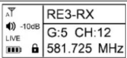
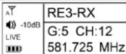
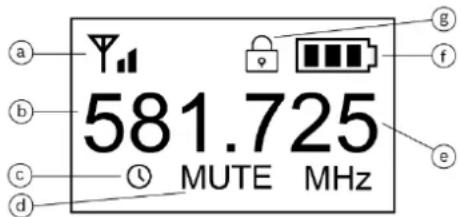
7.2 LCD display
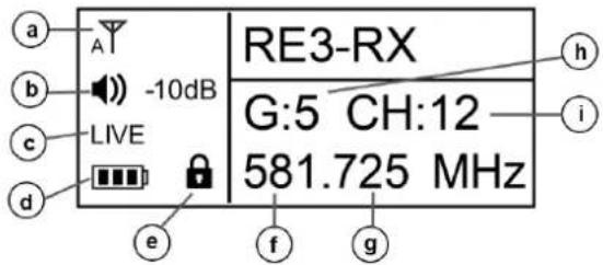
| ID | Item | Description, usage and notes | |
| a | Antenna status icon | A indicates the diversity circuit is choosing antenna A signal at the moment. T_B indicates the diversity circuit is choosing antenna B signal at the moment. T_x indicates there is no antenna signal present for the diversity circuit to choose. | |
| b | Audio output volume level | Displays the receiver audio output volume level. Menu item adjustment allows settings between 0dB to -50dB in 1dB increments. Beyond -50 is MUTE. | |
| c | Transmitter activity status | Displays the following possible transmitter audio states:LIVE indicates mated transmitter audio is live and present at the receiver.MUTE indicates mated transmitter is in mute mode.NoSYNC indicates no synced transmitter is on. | |
| d | Mated transmitter battery status icon | Indicates the synced transmitter's battery life.\( \boxed{\boxed{\boxed{\boxed{\boxed{\boxed{\boxed{\boxed{\boxed{\boxed{\boxed{\boxed{\boxed{\boxed{\boxed{\boxed{\boxed{\boxed{\boxed{\boxed{\boxed{\boxed{\boxed{\boxed{\boxed{\boxed{\boxed{\boxed{\boxed{\boxed{\boxed{\boxed{\boxed{\boxed{\boxed{\boxed{\boxed{\boxed{\boxed{\boxed{\boxed{\boxed{\boxed{\boxed{\boxed{\boxed{\boxed{\boxed{\boxed{\boxed{\boxed{boxed{\boxed{\boxed{\boxed{\boxed{\boxed{\boxed{\boxed{\boxed{\boxed{\boxed{\boxed{\boxed{\boxed{\boxed{\boxed{\boxed{\boxed{\boxed{\boxed{\boxed{\boxed{\boxed{\boxed{\boxed{\boxed{\boxed{\boxed{\boxed{\boxed{\boxed{\boxed{\boxed{\boxed{\boxed{\boxed{\boxed{\boxed{\boxed{\boxed{\boxed{\boxed{\boxed{\boxed{\boxed{\boxed{\boxed{\boxed{\boxed{\boxed {\boxed{\boxed{\boxed{\boxed{\boxed{\boxed{\boxed{\boxed{\boxed{\boxed{\boxed{\boxed{\boxed{\boxed{\boxed{\boxed{\boxed{\boxed{\boxed{\boxed{\boxed{\boxed{\boxed{\boxed{\boxed{\boxed{\boxed{\boxed{\boxed{\boxed{\boxed{\boxed{\boxed{\boxed{\boxed{\boxed{\boxed{\boxed{\boxed{\boxed{\boxed{\boxed{\boxed{\boxed{\boxed{\boxed{\boxed{\boxed{\boxed{\boxed}{\boxed{\boxed{\boxed{\boxed{\boxed{\boxed{\boxed{\boxed{\boxed{\boxed{\boxed{\boxed{\boxed{\boxed{\boxed{\boxed{\boxed{\boxed{\boxed{\boxed{\boxed{\boxed{\boxed{\boxed{\boxed{\boxed{\boxed{\boxed{\boxed{\boxed{\boxed{\boxed{\boxed{\boxed{\boxed{\boxed{\boxed{\boxed{\boxed{\boxed{\boxed{\boxed{\boxed{\boxed{\boxed{\boxed{\boxed{\boxed{\boxed{\boxed{-}}}}}}} = between 40% and 100% charge remains.\( \boxed{\boxed{\boxed{\boxed{\boxed{\boxed{\boxed{\boxed{\boxed{\boxed{\boxed{\boxed{\boxed{\boxed{\boxed{\boxed{\boxed{\boxed{\boxed{\boxed{\boxed{\boxed{\boxed{\boxed{\boxed{\boxed{\boxed{\boxed{\boxed{\boxed{\boxed{\boxed{\boxed{\boxed{\boxed{\boxed{\boxed{\boxed{\boxed{\boxed{\boxed{\boxed{\boxed{\boxed{\boxed{\boxed{\boxed{\boxed{\begin{array}{}}}}}}}}}}= between 40% and 100% charge remains.\( \boxed{\boxed{\boxed{\boxed{\boxed{\boxed{\boxed{\boxed{\boxed{\boxed{\boxed{\boxed{\boxed{\boxed{\boxed{\boxed{\boxed{\boxed{\boxed{\boxed{\boxed{\boxed{\boxed{\boxed{\boxed{\boxed{\boxed{\boxed{\boxed{\boxed{\boxed{\boxed{\boxed{\boxed{\boxed{\boxed{\boxed{\boxed{\boxed{\boxed{\boxed{\boxed{boxed{\boxed{\boxed{\boxed{\boxed{\boxed{\boxed{\boxed{boxed{\boxed{\boxed{\boxed{\boxed{\boxed{\boxed{\boxed{\boxed{\boxed{\boxed{\boxed{\boxed{\boxed{\boxed{\boxed{\boxed{\boxed{\boxed{\boxed{\boxed{\boxed{\boxed{\boxed{\boxed{\boxed{\boxed{\boxed{\boxed{\boxed{\boxed{\boxed{\boxed{\boxed{\boxed{\boxed{\boxed{\boxed{\boxed{\boxed{\boxed{\boxed{boxed{\boxed{\boxed{\boxed{\boxed{\boxed{\boxed{\boxed{-}}}}}}}}}}}}= between 40% and 100% charge remains.\( \boxed{\boxed{\boxed{\boxed{\boxed{\boxed{\boxed{\boxed{\boxed{\boxed{\boxed{\boxed{\boxed{\boxed{\boxed{\boxed{\boxed{\boxed{\boxed{\boxed{\boxed{\boxed{\boxed{\boxed{\boxed{\boxed{\boxed{\boxed{\boxed{\boxed{\boxed{\boxed{\boxed{\boxed{\boxed{\boxed{\boxed{\boxed{\boxed{boxed{\boxed{\boxed{\boxed{\boxed{\boxed{\boxed{\boxed{\boxed{\boxed{\boxed{boxed{\boxed{\boxed{\boxed{\boxed{\boxed{\boxed{\boxed{\boxed{\boxed{\boxed{\boxed{\boxed{\boxed{\boxed{\boxed{\boxed{\boxed{\boxed{\boxed{\boxed{\boxed{\boxed{\boxed{\boxed{\boxed{\boxed{\boxed{\boxed{\boxed{\boxed{\boxed{\boxed{\boxed{\boxed{\boxed{\boxed{\boxed{\boxed{boxed{\boxed{\boxed{\boxed{\boxed{\boxed{\boxed{\boxed{\boxed{\boxed{\boxed{{\begin{array}{}}}}}}}}}}}}= between 40% and 100% charge remains.\( \boxed{\boxed{\boxed{\boxed{\boxed{\boxed{\boxed{\boxed{\boxed{\boxed{\boxed{\boxed{\boxed{\boxed{\boxed{\boxed{\boxed{\boxed{\boxed{\boxed{\boxed{\boxed{\boxed{\boxed{\boxed{\boxed{\boxed{\boxed{\boxed{\boxed{\boxed{\boxed{\boxed{\boxed{\boxed{\boxed{\boxed{\boxed{\Box}}}}}}}}}}= between 40% and 100% charge remains.\( \boxed{\boxed{\boxed{\boxed{\boxed{\boxed{\boxed{\boxed{\boxed{\boxed{\boxed{\boxed{\boxed{\boxed{\boxed{\boxed{\boxed{\boxed{\boxed{\boxed{\boxed{\boxed{\boxed{\boxed{\boxed{\boxed{\boxed{\boxed{\boxed{\boxed{\boxed{\boxed{\boxed{\boxed{\boxed{\boxed{\boxed{\boxed{\boxed{{\begin{array}{}}}}}}}}}}}}= between 40% and 100% charge remains.\( \boxed{\boxed{\boxed{\boxed{\boxed{\boxed{\boxed{\boxed{\boxed{\boxed{\boxed{\boxed{\boxed{\boxed{\boxed{\boxed{\boxed{\boxed{\boxed{\boxed{\boxed{\boxed{\boxed{\boxed{\boxed{boxed{\boxed{\boxed{\boxed{\boxed{\boxed{\boxed{\boxed{\boxed{\boxed{\boxed{\boxed{\boxed{\boxed{\boxed{\boxed{\boxed{\boxed{\boxed{\boxed{\boxed{\boxed{\boxed{\boxed{\boxed{boxed{\boxed{\boxed{\boxed{\boxed{\boxed{\boxed{\boxed{\boxed{\boxed{\boxed{\boxed{\boxed{\boxed{\boxed{\boxed{\boxed{\boxed{\boxed{\boxed{\boxed{\boxed{\boxed{\boxed{\boxed{-}}}}}}}}}}= between 40% and 100% charge remains.\( \boxed{\boxed{\boxed{\boxed{\boxed{\boxed{\boxed{\boxed{\boxed{\boxed{\boxed{\boxed{\boxed{\boxed{\boxed{\boxed{\boxed{\boxed{\boxed{\boxed{\boxed{\boxed{\boxed{\boxed{\boxed{\boxed{\boxed{\boxed{\boxed{\boxed{\boxed{\boxed{\boxed{\boxed{\boxed{\boxed{\boxed{\boxed{\boxed{-}}}}}}}}}}= between 40% and 100% charge remains.\( \boxed{\boxed{\boxed{\boxed{\boxed{\boxed{\boxed{\boxed{\boxed{\boxed{\boxed{\boxed{\boxed{\boxed{boxed{\boxed{\boxed{\boxed{\boxed{\boxed{\boxed{\boxed{\boxed{\boxed{\boxed{\boxed{\boxed{\boxed{\boxed{\boxed{\boxed{\boxed{\boxed{\boxed{\boxed{\boxed{\boxed{boxed{\boxed{boxed{\boxed{boxed{\boxed{boxed{\boxed{boxed{\boxed{boxed{\boxed{boxed{\boxed{boxed{\boxed{boxed{\boxed{boxed{\boxed{boxed{\boxed{boxed{\boxed{boxed{\boxed{boxed{\boxed{boxed{\boxed{boxed{\boxed{boxed{\boxed{boxed{\boxed{boxed{\boxed{boxed{\boxed{boxed{\boxed{boxed{\boxed{boxed{\boxed{boxed{\boxed{boxed{\boxed{\boxed{boxed{\boxed{boxed{\boxed{boxed{\boxed{boxed{\boxed{boxed{\boxed{boxed{\boxed{boxed{\boxed{boxed{\boxed{boxed{\boxed{boxed{\boxed{boxed{\boxed{boxed{\boxed{boxed{\boxed{boxed{\boxed{boxed{\boxed{boxed{\boxed{boxed{\boxed{boxed{\boxed{boxed{\boxed{boxed{\boxed{boxed{\boxed{boxed{\boxed{boxed{\boxed{boxed{boxed{\boxed{boxed{\boxed{boxed{\boxed{boxed{\boxed{boxed{\boxed{boxed{\boxed{boxed{\boxed{boxed{\boxed{boxed{\boxed{boxed{\boxed{boxed{\boxed{boxed{\boxed{boxed{\boxed{boxed{\boxed{boxed{\boxed{boxed{\boxed{boxed{\boxed{boxed{\boxed{boxed{\boxed{boxed{\boxed{boxed{\boxed{boxed{\boxed{boxed{\boxed{boxed{\boxed{boxed{boxed{boxed{\boxed{boxed{\boxed{boxed{\boxed{boxed{\boxed{boxed{\boxed{boxed{\boxed{boxed{\boxed{boxed{\boxed{boxed{\boxed{boxed{\boxed{boxed{\boxed{boxed{\boxed{boxed{\boxed{boxed{\boxed{boxed{\boxed{boxed{\boxed{boxed{\boxed{boxed{\boxed{boxed{\boxed{boxed{\boxed{boxed{\boxed{boxed{\boxed{boxed{\boxed{boxed{\boxed{\boxed{\boxed{boxed{\boxed{boxed{\boxed{boxed{\boxed{boxed{\boxed{boxed{\boxed{boxed{\boxed{boxed{\boxed{boxed{\boxed{boxed{\boxed{boxed{\boxed{boxed{\boxed{boxed{\boxed{boxed{\boxed{boxed{\boxed{boxed{\boxed{boxed{\boxed{boxed{\boxed{boxed{\boxed{boxed{\boxed{boxed{\boxed{boxed{\boxed{boxed{\boxed{boxed{\boxed{\boxed{boxed{boxed{\boxed{boxed{\boxed{boxed{\boxed{boxed{\boxed{boxed{\boxed{boxed{\boxed{boxed{\boxed{boxed{\boxed{boxed{\boxed{boxed{\boxed{boxed{\boxed{boxed{\boxed{boxed{\boxed{boxed{\boxed{boxed{\boxed{boxed{\boxed{boxed{\boxed{boxed{\boxed{boxed{\boxed{boxed{\boxed{boxed{\boxed{boxed{\boxed{boxed{\boxed{boxed{boxed{\boxed{\boxed{boxed{\boxed{boxed{\boxed{boxed{\boxed{boxed{\boxed{boxed{\boxed{boxed{\boxed{boxed{\boxed{boxed{\boxed{boxed{\boxed{boxed{\boxed{boxed{\boxed{boxed{\boxed{boxed{\boxed{boxed{\boxed{boxed{\boxed{boxed{\boxed{boxed{\boxed{boxed{\boxed{boxed{\boxed{boxed{\boxed{boxed{\boxed{boxed{\boxed{boxed{\boxed{\boxed{\boxed{\boxed{boxed{\boxed{boxed{\boxed{boxed{\boxed{boxed{\boxed{boxed{\boxed{boxed{\boxed{boxed{\boxed{boxed{\boxed{boxed{\boxed{boxed{\boxed{boxed{\boxed{boxed{\boxed{boxed{\boxed{boxed{\boxed{boxed{\boxed{boxed{\boxed{boxed{\boxed{boxed{\boxed{boxed{\boxed{boxed{\boxed{boxed{\boxed{boxed{\boxed{boxed{boxed{\boxed{boxed{boxed{\boxed{boxed{\boxed{boxed{\boxed{boxed{\boxed{boxed{\boxed{boxed{\boxed{boxed{\boxed{boxed{\boxed{boxed{\boxed{boxed{\boxed{boxed{\boxed{boxed{\boxed{boxed{\boxed{boxed{\boxed{boxed{\boxed{boxed{\boxed{boxed{\boxed{boxed{\boxed{boxed{\boxed{boxed{\boxed{boxed{\boxed{boxed{\boxed{boxed{\boxed{\boxed{boxed{\boxed{\boxed{boxed{\boxed{boxed{\boxed{boxed{\boxed{boxed{\boxed{boxed{\boxed{boxed{\boxed{boxed{\boxed{boxed{\boxed{boxed{\boxed{boxed{\boxed{boxed{\boxed{boxed{\boxed{boxed{\boxed{boxed{\boxed{boxed{\boxed{boxed{\boxed{boxed{\boxed{boxed{\boxed{boxed{\boxed{boxed{\boxed{boxed{\boxed{boxed{\boxed{boxed{boxed{\boxed{\boxed{\boxed{boxed{\boxed{boxed{\boxed{boxed{\boxed{boxed{\boxed{boxed{\boxed{boxed{\boxed{boxed{\boxed{boxed{\boxed{boxed{\boxed{boxed{\boxed{boxed{\boxed{boxed{\boxed{boxed{\boxed{boxed{\boxed{boxed{\boxed{boxed{\boxed{boxed{\boxed{boxed{\boxed{boxed{\boxed{boxed{\boxed{boxed{\boxed{boxed{\boxed{boxed{boxed{boxed{\boxed{\boxed{boxed{\boxed{boxed{\boxed{boxed{\boxed{boxed{\boxed{boxed{\boxed{boxed{\boxed{boxed{\boxed{boxed{\boxed{boxed{\boxed{boxed{\boxed{boxed{\boxed{boxed{\boxed{boxed{\boxed{boxed{\boxed{boxed{\boxed{boxed{\boxed{boxed{\boxed{boxed{\boxed{boxed{\boxed{boxed{\boxed{boxed{\boxed{boxed{\boxed{boxed{boxed{boxed{boxed{\boxed{boxed{\boxed{boxed{\boxed{boxed{\boxed{boxed{\boxed{boxed{\boxed{boxed{\boxed{boxed{\boxed{boxed{\boxed{boxed{\boxed{boxed{\boxed{boxed{\boxed{boxed{\boxed{boxed{\boxed{boxed{\boxed{boxed{\boxed{boxed{\boxed{boxed{\boxed{boxed{\boxed{boxed{\boxed{boxed{\boxed{boxed{\boxed{boxed{\boxed{boxed{boxed{boxed{boxed{boxed{\boxed{boxed{\boxed{boxed{\boxed{boxed{\boxed{boxed{\boxed{boxed{\boxed{boxed{\boxed{boxed{\boxed{boxed{\boxed{boxed{\boxed{boxed{\boxed{boxed{\boxed{boxed{\boxed{boxed{\boxed{boxed{\boxed{boxed{\boxed{boxed{\boxed{boxed{\boxed{boxed{\boxed{boxed{\boxed{boxed{\boxed{boxed{\boxed{boxed{\boxed{\boxed{boxed{boxed{boxed{\boxed{boxed{\boxed{boxed{\boxed{boxed{\boxed{boxed{\boxed{boxed{\boxed{boxed{\boxed{boxed{\boxed{boxed{\boxed{boxed{\boxed{boxed{\boxed{boxed{\boxed{boxed{\:}}}}}}}}}}}}= between 40% and 100% charge remains.\( \boxed{\text{[~]}}}}}}}}= between 40\% and 100\% charge remains.\( \text{[~]}}}}}}}}= between 40\% and 100\% charge remains.\( \text{[~]}}}}}}= between 40\% and 100\% charge remains.\( \text{[~]}}}}}}}}= between 40\% and 100\% charge remains.\( \text{[~]}}}}}}}}= between 40\% and 100\% charge remains.\( \text{[~]}}}}}}}}= between 40\% and 100\% charge remains.\( \text{[~]}}}}}}= between 40\% and 100\% charge remains.\( \text{[~]}}}}}}}}= between 40\% of charge remains.\( \text{[~]}}}}}}}}= between 40\% of charge remains.\( \text{[~]}}}}}}}}= between 40\% of charge remains.\( \text{[~]}}}}}}}}= between 40\% of charge remains.\( \text{[~]}}}}}}}}= between 40\% of charge remains.\( \text{[~]}}}}} = between 40\% of charge remains.\( \text{[~]}}}}}}}}= between 40\% of charge remains.\( \text{[~]}}}}}}= between 40\% of charge remains.\( \text{[~]}}}}}}}}= between 40\% of charge remains.\( \text{[~]}}}}}}}}= between 40\% of charge remains.\( \text{[~]}}}}}}}}= between 40\% of charge remains.\( \text{[~]}}}}}}}}= between 40\% of 100\% charge remains.\( \text{[~]}}}}}}}}= between 40\% of charge remains.\( \text{[~]}}}}}}}}= between 40\% of 100\% charge remains.\( \text{[~]}}}}}}}}= between 40\% of 100\% charge remains.\( \text{[~]}}}}}}}}= between 40\% of 100\% charge remains.\( \text{[~]}}}}}}}}= between 40\% of 100\% charge remains.\( \text{[~]}}}}}}}}= below 40\% of 100\% charge remains.\( \text{[~]}}}}}}}}}}= below 40\% of 100\% charge remains.\( \text{[~]}}}}}}}}}}= below 40\% of 100\% charge remains.\( \text{[~]}}}}}}}}}}= below 40\% of 100\% charge remains.\( \text{[~]}}}}}}}}}}= below 40\% of all 100\% charge remains.\( \text{[~]}}}}}}}}}}= below 40\% of 100\% charge remains.\( \text{[~]}}}}}}}}= below 40\% of 100\% charge remains.\( \text{[~]}}}}}}}}}}= below 40\% of 100\% charge remains.\( \text{[~]}}}}}}}}}}= below 40\% of 100\% charge remain.\( \text{[~]}}}}}}}}}}= below 40\% of 100\% charge remains.\( \text{[~]}}}}}}}}}}= below 40\% of 100\% charge remains.\( \text{[~]}}}}}}}}= below 40\% of 100\% charge remains.\( \text{[~]}}}}}}}}= below 40\% of 100\% charge remains.\( \text{[~]}}}}}}}}= below 40\% of 100\% charge remains.\( \text{[~]}}}}}}}}= below 40\% of 10 0% charge remains.\( \text{[~]}}}}}}}}= below 40\% of 100\% charge remains.\( \text{[~]}}}}}}}}= below 40\% of 100\% charge remains.\( \text{[~]}}}}}}}}= below 40\% of 100\% charge remains.\( \text{[~]}}}}}}= below 40\% of 100\% charge remains.\( \text{[~]}}}}}}= below 40\% of 100\% charge remains.\( \text{[~]}}}}}}= below 40\% of 100\% charge remains.\( \text{[~]}}}}}}= below 40\% of 100\% charge remained.\( \text{[~]}}}}}}= below 40\% of 100\% charge remains.\( \text{[~]}}}}}}= below 40\% of 100\% charge remains.\( \text{[~]}}}}}}= below 40\% of 100\% charge remains.\( \text{[~]}}}}}}= below 40\% OF 100\% charge remains.\( \text{[~]}}}}}}= below 40\% of 100\% charge remains.\( \text{[~]}}}}}}= below 40\% of 100\% charge remains.\( \text{[~]}}}}}}= below 40\% of 100\% charge remains.\( \text{[~]}}}}}}}=\ below 40\% of 100\% charge remains.\( \text{[~]}}}}}}= below 40\% of 100\% charge remains.\( \text{[~]}}}}}}= below 40\% of 100\% charge remains.\( \text{[~]}}}}}}= below 40\% of 100\% charge remains.\( \mathrm{[~]}}}}}}= below 40\% of 100\% charge remains.\( \text{[~]}}}}}}= below 40\% of 100\% charge remains.\( \text{[~]}}}}}}= below 40\% of 100\% charge remains.\( \text{[~]}}}}}}= below 40\% of 10 0% charge remains.\( \text{[~]}}}}}}= below 40\% of 100\% charge remains.\( \text{[~]}}}}}}= below 40\% of 100\% charge remains.\( \text{[~]}}}}}}= below 40\% of 100\% charge remains.\( \text{[~]}}}}}}= below 4 0% of 100\% charge remains.\( \text{[~]}}}}}}= below 40\% of 100\% charge remains.\( \text{[~]}}}}}}= below 40\% of 100\% charge remains.\( \text{[~]}}}}}}= below 40\% of 100\% charge remains.\( \text{[~] |
| i | Channel | The channel number of the receiver's tuned frequency. |
7.3 RE3-RX setup menu
7.3.1 RE3-RX menu operation
Navigating and using the RE3-RX menu system is simple and intuitive. To change from the home screen to the menu, press and hold the SET button for three seconds.
SET is the most commonly used menu navigation button. It is a multi-purpose action button which functions as an enter key, a menu advance key, an item select key, and a save or store key.
Use the ▲ and ▼ navigation buttons to scroll through menus and change values or item states.
SYNC serves as a menu exit button while in menu or edit menu modes. Briefly press once to return to the previous menu without saving any changes made. Briefly pressing multiple times will escape back the number of menus relative to the number of button pushes made with a final destination of the home screen.
NOTE: Once saved and stored, menu setting changes are recalled the next time receiver is powered up.
NOTE: Remember to SAVE wanted edits prior to escaping out of a submenu.
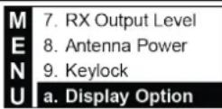
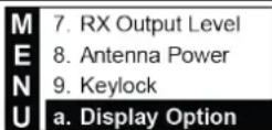
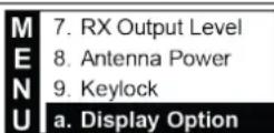
7.3.2 Menu items overview
Steps to navigating operating menu and submenus:
- Press and hold SET for three seconds.
- Scroll up and down using the ▲ and ▼ buttons.
- Press SET to select an item for investigation or editing. Also, press SET to advance to some submenu option parameters.
| 1. Scan | |
| 2. Frequency | |
| M | 3. Group/Channel |
| 4. Squelch | |
| E | 5. Mic Config |
| 6. Volume | |
| N | 7. RX Output Level |
| 8. Antenna Power | |
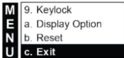
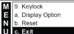
| U | 9. Keylock |
| a. Display Option | |
| b. Reset | |
| c. Exit |
| Item | Description |
| 1. Scan | Submenu selection to scan for open frequencies. Selecting opens scan submenu. |
| 2. Frequency | Submenu selection to access manual control in setting frequency.Selecting opens frequency submenu. |
| 3. Group/Channel | Submenu selection to access manual control in setting group and channel. Selecting opens Group/Channel submenu. |
| 4. Squelch | Submenu selection to access squelch setting to control background radio noise. Selecting opens squelch submenu. Factory default is 0 (zero). |
| 5. Mic Config | Submenu selection to access a variety of microphone transmitter parameters, which transfer to the transmitter during SYNC operation.Selecting opens MicConfig submenu. |
| 6. Volume | Submenu selection to access manual control of receiver output volume. Selecting opens setup volume submenu. |
| 7. RX output level | Submenu selection to access manual control of receiver output level.Selecting opens output level submenu where MIC level or LINE level are options. |
| 8. Antenna Power | Submenu selection to access manual control of receiver antenna booster feed voltage. Selecting opens Antenna Power submenu where ON and OFF are options. Factory default is ON. |
| 9. Keylock | Submenu selection to access manual control of Keylock feature operating status. Selecting opens Keylock where ON and OFF are options. Factory default is OFF. |
| a. Display option | Submenu selection to access manual control of receiver display characteristics. Selecting opens Display Options submenu where contrast and brightness are controlled. Factory defaults are 4. |
| b. Reset | Submenu selection to access a manual receiver reset to factory default settings. Selecting opens reset submenu. |
| c. Exit | Returns to home screen. |
7.3.3 Scanning for open channels
Three methods are available. 1) Briefly press the SCAN button on the front panel to open the Scan submenu (arrive at step 1 below). 2) Press and hold SCAN button on the front panel for 3 seconds to enter "Scan All Groups" dialog (arrive at step 2 below). 3) Select 1 from the main menu to open Scan submenu.
1 Select 1. All Groups and press SET to begin scan process.
| M | 1. All Groups |
| E | 2. Result List |
| N | 3. Current Group |
| U | 4. Return |
| 2 Press SET to start, or SYNC to quit. | 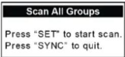 | |
| 3 Wait for scanning process to complete. |  | |
| 4 | When scan is complete, view the results list.Scroll through groups using ▲ or ▼ noting open channel quantity per group.Press SET on the group number having the number of open channels which best meets your wireless system needs. This advances to the CH number. | 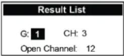 |
| 5 | CH number is highlighted and displays the first open channel in the group. While highlighted, scrolling through the open channels using ▲ or ▼ will identify all open channels in the group. Note that some channel numbers will not appear as they are not open at the time of the scan.Press SET on CH number. This selects that group and channel the set will operate on. |  |
| 6 | This also returns to Result List on the scan menu. |  |
| 7 | Either scroll ▼ down to Exit and press SET, or press SYNC on the receiver front panel to return to the home screen. The selected Group/Channel and associated Frequency displays on the home screen. |   |
NOTE: This group and channel must be set on the transmitter as well. Follow the SYNC operation steps to sync the transmitter to the receiver, or manually set the transmitter to this group and channel.
NOTE: This process is required for any system of sets, either a single set system, or a multi-channel system.
ALL SETS in a multi-channel system operating on the same frequency band MUST use the same group number.
7.3.4 Using the result list during the same session
A session is the period of time after a scan has been performed prior to a receiver power-down. All scan data is stored in temporary memory until power-down. The session expires upon receiver power-down.
During a session, you can return to the result list to select a different group and channel, or just a different channel within the same group.
| 1 | Enter the main menu and select Scan by pressing SET. | MENU | 1. Scan2. Frequency3. Group/Channel4. Squelch |
| 2 | Press ▼ to scroll down to Result List. Press SET to enter Result List. | MENU | 1. All Groups2. Result List3. Current Group4. Return |
| 3 | Scroll through groups using the ▲ or ▼ buttons noting open channel quantity per group. Select either the same previous group or a new group by pressing SET. This advances to the channel and CH # highlights. | Result ListG: 1 CH: 3Open Channel: 12 | |
| 4 | Press the ▲ or ▼ button to scroll through open channels. Note that some channel numbers may be skipped because they were not clear at the time of the scan. Press SET on CH number.This selects that group and channel the set will operate on. | Result ListG: 5 CH: 12Open Channel: 15 | |
| 5 | This also returns to Result List on the scan menu. | MENU | 1. All Groups2. Result List3. Current Group4. Return |
| 6 | Either scroll ▼down to Exit and press SET, or briefly press SYNC on the receiver front panel to escape to the home screen. The selected Group/Channel and associated Frequency displays on the home screen. | MENU | 9. Keylocka. Display Optionb. Resetc. ExitORSYNC |
7.3.5 Scanning current group
The current assigned group, or a particular selected group can be scanned individually. This process will locate clear channels within that group individually.
| 1 | Enter the main menu and select Scan by pressing SET. | MENU | 1. Scan2. Frequency3. Group/Channel4. Squelch |
| 2 | Press the ▼ button to scroll down to Current Group. Press SET to enter Result List. | MENU | 1. All Groups2. Result List3. Current Group4. Return |
| 3 | The current assigned group is displayed. Prepare to scan that group, or scroll through other groups using ▲ or ▼.Select the group to scan by pressing SET. The scan of that group begins. When the scan is complete, the highlight box advances to channel, and the first clear channel in that group appears. | |
| 4 | Either press SET to save the channel displayed and exit, or press ▲ or ▼ to scroll through to locate the next open channel. A brief scan occurs while locating the next clear channel. Some channel numbers may be skipped because they were not clear at the time of the scan. Press SET to save. This selects that group and channel the set will operate on. | |
| 5 | This returns to Current Group on the scan menu. | MENU 1. All Groups2. Result List3. Current Group4. Return |
| 6 | Either scroll ▼down to Exit and press SET, or briefly press SYNC on the receiver front panel to return to the home screen. The selected Group/Channel and associated Frequency displays on the home screen. | MENU 9. Keylocka. Display Optionb. Resetc. ExitORSYNC |
7.3.6 Return
Selecting Return in the Scan menu returns to the main menu.
| 1 | While in the Scan menu, press the ▼ button to scroll down to Return. Press SET. | MENU | 1. All Groups2. Result List3. Current Group4. Return |
| 2 | The screen returns to the main menu. | MENU | 1. Scan2. Frequency3. Group/Channel4. Squelch |
| 3 | Either scroll ▼down to Exit and press SET, or briefly press SYNC on the receiver front panel to return to the home screen. | MENU | 9. Keylocka. Display Optionb. Resetc. ExitORSYNC |
| 4 | Home screen | ATLIVE | RE3-RXG:5 CH:12581.725 MHz |
7.3.7 Manually setting frequency
Setting custom frequencies manually does not benefit from the scan function of locating clear channels. It is important to note that manually entered custom frequencies may experience interference, which can be avoided by using the scan function.
| 1 | Press the▼button to scroll down to Frequency on the main menu. Select by pressing SET to enter the Setup Frequency screen. |  |
| 2 | The three digits to the left of the decimal are in millions (MHz) and are highlighted. Pressing▲increases frequency in increments of 1 MHz per press, pressing▼decreases frequency in increments of 1 MHz per press. Press SET to move to next set of three digits. |  |
| 3 | The three digits to the right of the decimal are in thousands (kHz). Pressing▲increases frequency in increments of 25 kHz per press,▼decreases frequency in increments of 25 kHz per press.The G:__ and CH:__ under the frequency will populate when a preset group and channel match the frequency dialed in. | 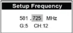 |
| 4 | Press SET to save the custom frequency and to exit to the main menu. | 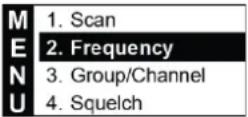 |
| 5 | Either scroll▼down to Exit and press SET, or briefly press SYNC on the receiver front panel to return to the home screen. The selected custom Frequency displays on the home screen. | 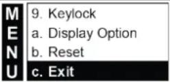  |
7.3.8 Manually setting group and channel
Setting group and channel manually does not benefit from the scan function of locating clear channels. It is important to note that manually entered group/channel combination may experience interference, which can be avoided by using the scan function.
Press the ▼ button to scroll down to Group/Channel on the main menu. Select by pressing SET to enter the Setup Group screen.

| 2 | The current selected group number is highlighted. Pressing▲ increases the group number (1-8) in single digit increments, and pressing▼ decreases the group number (1-8) in single digit increments. Press SET to move to Channel. | 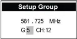 |
| 3 | The current selected channel number is highlighted. Pressir▲ increases the channel number (up to max of 22) in single digit increments, and pressing▼ decreases the channel number in single digit increments. The frequencies above the G:__ CH__ change to display the frequency of the changed group and channel. | 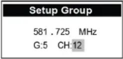 |
| 4 | Press SET to save the chosen Group/Channel and return to the main menu. |  |
| 5 | Either scroll▼down to Exit and press SET, or briefly press SYNC on the receiver front panel to return to the home screen. The selected custom Frequency displays on the home screen. | 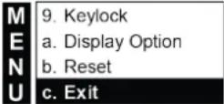 |
 |
7.3.9 Adjusting receiver squelch
Setting the squelch appropriately based on conditions is important to controlling background radio noise, as well as maintaining the desired radio system range (the functional distance between transmitter and receiver antennas). Squelch is basically a noise gate across the receiver's audio path that is keyed open by a combination of audio path signal level, and the presence of a unique combination of tone codes in the received signal. Squelch sets the threshold where the received signal amplitude will open the noise gate. Signals above the threshold will open the audio path gate, while signal levels below the threshold will not open the gate.
NOTE: Improperly set squelch negatively affects system range (the distance between transmitter and receiver).
Press the ▼ button to scroll down to Squelch on the main menu. Select by pressing SET to enter the Setup Squelch screen.

The display shows the current squelch setting. The numbers on this scale are arbitrary values from -5 to the left of 0, to +10 to the right of 0. Higher number values tighten the gate threshold, while lower number values loosen the gate threshold.
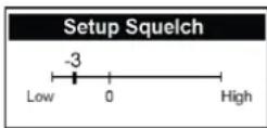
3
Pressing the ▲ button moves the fader bar to the right while increasing the displayed value in single digit increments thereby tightening the noise gate, and pressing the ▼ button moves the fader bar to the left while decreasing the displayed value in single digit increments thereby loosening the noise gate.
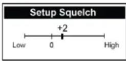
4 Press SET to save and return to main menu.

Either scroll ▼down to Exit and press SET, or briefly press SYNC on the receiver front panel to return to the home screen.
OR

7.3.10 Mic Config submenu
Operating parameters of the transmitter can be set up within the MicConfig submenu and written to the transmitter during the SYNC operation.
Enter the submenu as follows:
| 1 | Press the ▼ or ▲ button to scroll to MicConfig in the main menu. Select by pressing SET to enter the MicConfig screen. | MENU2. Frequency3. Group/Channel4. Squelch5. Mic Config |
| 2 | Press the ▼ or ▲ button to highlight the item to edit. | |
| 3 | Press SET to toggle over and highlight the parameter on the right. | |
| 4 | When highlighted, press ▼ or ▲ to make numerical or status changes to that parameter. | |
| 5 | Press SET to toggle back to the menu option side on left. | |
| 6 | Continue to scroll ▼ or ▲ to other items for editing. | |
| 7 | When finished, scroll to Save Settings and press SET to save settings to prevent settings being lost. | |
| 8 | Exit Without Save option exits to the main menu without save. | |
Parameter description and setting options:
| Sensitivity | -3dB | |
| M | Attenuate | OFF |
| RFPower | Low | |
| E | AutoOFF | OFF |
| KeyLock | OFF | |
| N | Mic Display | Freq. |
| SYNC Config | ||
| U | Save Settings | |
| Exit Without Save |
| Item | Description | Setting options |
| Sensitivity | A means for the transmitter audio input stage to match the output of the connected microphone. Lower values may produce lower transmitter audio gain. Higher values may produce higher transmitter audio gain. | -15dB, -12dB, -9dB, -6dB, -3dB, 0dB, 3dB, 6dB, 9dB, 12dB, 15dB |
| Attenuate | When set to on, the transmitter audio input stage is attenuated by 20dB, reducing the gain between the microphone output and the transmitter's audio input preamp. | Off or On |
| RFPower | Selects transmitter RF output power. This option is band specific.NOTE: 8M Band is not adjustable. | Lo or High |
| AutoOFF | Assigns a time period for the transmitter to automatically turn off once mute is engaged to conserve battery life. | Off, 1 minute, 10 minutes, and 30 minutes |
| KeyLock | Prevents unwanted tampering with, or changes to transmitter parameter settings. | Off or On |
| Mic Display | Selects the tuning information displayed on the transmitter home screen. | Freq. or GP/CH |
| SYNC Config | Allows selection of MicConfig items synced to the transmitter during SYNC operation. Scroll with the ▼ and ▲ buttons. Select or deselect using SET. | ☐ Frequency☐ Sensitivity☐ Attenuate☐ RF Power☐ AutoOFF☐ KeyLockSave and Exit |
| Save Settings | Saves setting changes and exits to main menu. | |
| Exit Without Save | Exits to the main menu without saving changes. |
7.3.11 Adjusting receiver volume
Setting the receiver output gain through menu item 6, Volume sets the gain leaving the receiver and arriving at the destination circuit; either a microphone preamp, or a line in preamp.
1 Press the ▼ button to scroll down to Volume from the main menu. Select by pressing SET to enter the Volume screen.

The display shows the current volume setting in dB of attenuation where 0 dB is the highest output volume, and -50 is the lowest output volume before mute.
Use the ▲ and ▼ buttons to adjust to the desired volume. Pressing ▲ increases the volume by 1 dB (press and hold the
3 ▲ button quickly increases the value) and pressing ▼ decreases the volume by 1 dB (press and hold ▼ button quickly decreases the value).
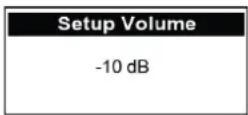
| 4 | Press SET to save changes and return to main menu. | 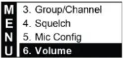 |
| 5 | Either scroll ▼down to Exit and press SET, or briefly press SYNC on the receiver front panel to return to the home screen. | 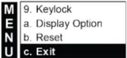 |
 |
7.3.12 Adjusting receiver output level
Setting the receiver output level through menu item 7, RX Output Level assigns either mic level, or line level to the receiver XLR and 14 ” TS output jacks. This is an important step in ensuring the signal level leaving the receiver is appropriate for the destination circuit of either a microphone preamp, or a line in preamp.
| 1 | Press the ▼ button to scroll down to RX Output Level from the main menu. Select by pressing SET to enter the RX Output Level screen. | 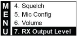 |
| 2 | The display shows the current volume setting of either MIC or LINE. |  |
| 3 | To select desired level, pressing the ▲ button toggles from MIC to LINE, and the ▼ button toggles from LINE to MIC. |  |
| 4 | Press SET to save changes and return to main menu. | 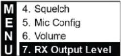 |
| 5 | Either scroll ▼down to Exit and press SET, or briefly press SYNC on the receiver front panel to return to the home screen. | 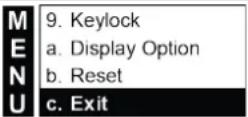  |
7.3.13 Turning antenna power on and off
The receiver antenna jacks can supply 12vDC booster feed to power the optional RFAMP booster, or ALPA active antenna.
| 1 | From the main menu, press the ▼ button to scroll down to Antenna Power. | MENU5. Mic Config6. Volume7. RX Output Level8. Antenna Power |
| 2 | The display choices are ON or OFF. | Antenna PowerONOFF |
| 3 | To select, pressing the ▲ button toggles from OFF to ON, and the ▼ button toggles from ON to OFF. | Antenna PowerONOFF |
| 4 | Press SET to save changes and return to main menu. | MENU5. Mic Config6. Volume7. RX Output Level8. Antenna Power |
| 5 | Either scroll ▼ down to Exit and press SET, or briefly press SYNC on the receiver front panel to return to the home screen. | MENU9. Keylocka. Display Optionb. Resetc. ExitORSYNC |
7.3.14 Keylock
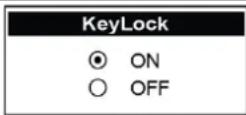
The receiver can be set to Keylock mode, thereby preventing unwanted tampering with, or changes to receiver parameter settings. Menu item 9, Keylock, accesses settings of either on or off.
To turn Keylock ON
| 1 | From the main menu, press the ▼ button to scroll down to Keylock. Select by pressing SET to enter the Keylock screen. | MENU | 6. Volume7. RX Output Level8. Antenna Power9. Keylock |
| 2 | The display shows the setting of OFF. | KeyLockONOFF | |
| 3 | Use the ▲ button to toggle from OFF to ON. | KeyLockONOFF | |
| 4 | Press SET to save changes. The display returns to the home screen where the 🔒 icon appears. Access to menus is now LOCKED until unlock is performed. | AT-10dBLIVELIVE | RE3-RXG:5 CH:12581.725 MHz |
To turn Keylock OFF
Entering the menus is not possible when Keylock is on. Keylock must be turned off to access menus.
1 Press and hold SET for two seconds to enter Keylock screen.
2 The display shows the setting of ON.
3 Press the▼ button to toggle from ON to OFF.
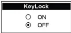
4 Press SET to save changes. The display returns to the home screen where the 🔒 icon no longer appears.
7.3.15 Adjusting display options: contrast and brightness
Adjustments to the display contrast and brightness are made in menu item a, Display Options.
Press the ▼ button to scroll down to Display Options from the main menu. Select by pressing SET to enter the Display Options screen where the screen shows the current settings.
Contrast setting is highlighted. To make any changes, press the ▲ button to assign higher contrast value, or press the ▼ button to assign lower contrast value. Press set to move to brightness.
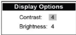
Current brightness value is highlighted. To make any changes, press the ▲ button to assign higher brightness value, or press the ▼ button to assign lower brightness value.
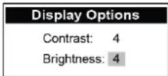
4 Press SET to save changes. The display then returns to the main menu.
5 Press SET to save. The display returns to the main menu.
Either scroll ▼down to Exit and press SET, or briefly press SYNC on the receiver front panel to return to the home
screen. The contrast and brightness changes will impact the appearance of all screens.
OR

7.3.16 System reset
Resetting the receiver in menu item b, Reset restores all settings to factory default. Be very sure you want to do this as all custom settings will be erased.
| 1 | Press the ▼ button to scroll down to Reset from the main menu. Select by pressing SET to enter the Reset screen. | 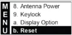 |
| 2 | The reset screen displays the warning message shown. No is highlighted as the default option. |  |
| 3 | Press ▲ to toggle to Yes.(NOTE: If Yes is highlighted and you wish to change to No, press the ▼ button to select and highlight No). |  |
| 4 | Press SET when you are sure of your choice.If No is selected, Cancel is displayed and the screen returns to the main menu.If Yes is selected, dialogs of “Resetting” and “Reboot” consecutively appear. The receiver restarts with factory default settings. The display then shows the home screen with G:1 and CH:1 as default. | 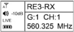 |
7.3.17 Exit
Select item c, Exit to return to home screen.
| 1 | From the main menu, press the▼button to scroll down to Exit. Press SET. | MENU | 9. Keylocka. Display Optionb. Resetc. Exit |
| 2 | The home screen displays. | ATLIVE-10dB | RE3-RXG:5 CH:12581.725 MHz |
8 RE3-HHT handheld transmitter
8.1 Product identification
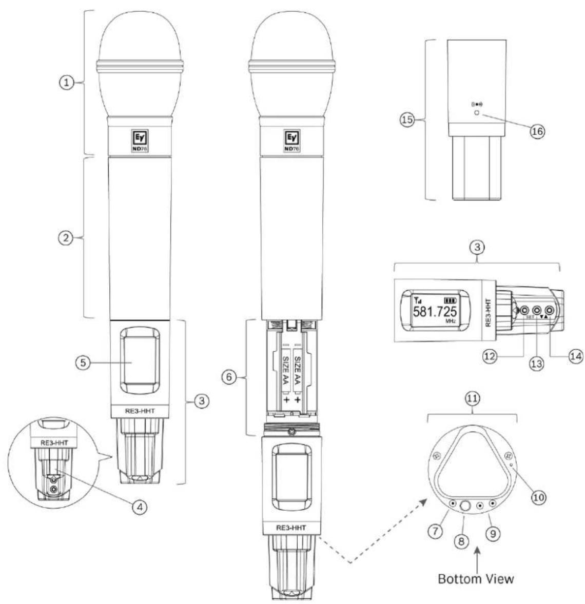
| ID | Item | Description, usage and notes |
| 1 | Microphone head | RE3 handheld transmitter sets are available with the following microphone head options: ND76-RC3, ND86-RC3, ND96-RC3, RE420-RC3, and RE520-RC3. The heads are interchangeable via the easy-to-use thread-on connection. |
| 2 | Transmitter handle / battery cover | This section provides a primary gripping and mounting area, and serves as sliding cover for the battery compartment. |
| 3 | Control section | This section contains the LCD display, three menu navigation buttons, power button, charging contacts, LED indicator, and the sync port on opposite side of display. |
| 4 | Sliding menu navigation button cover | This sliding cover protects the menu navigation buttons. Sliding the cover toward the LCD display reveals the buttons. Close the cover by sliding it in the other direction protects the buttons. |
| 5 | LCD Display | Backlit LCD displays all operating information and menus. |
| 6 | Battery compartment | Holds two AA or AA-size rechargeable cells. Install AA cells according to polarity orientation as shown. |
| 7 | Charging contact | Three charging contacts, one to the left of the power button and two to the right are for use when using the optional BC2 battery charger and rechargeable cells. |
| 8 | Power button | This is a multi-purpose button, functioning as a power on and off switch, a transmitter mute switch, as well as a menu escape switch.To power ON transmitter: press for one secondTo power OFF transmitter: press and hold until transmitter turns off. PW OFF is displayed.To MUTE transmitter: press briefly (less than one second). MUTE appears on LCD.To UNMUTE transmitter (when muted): press briefly (less than one second). MUTE disappears on LCD display.While in parameter edit mode, press to return to home screen.CANCEL appears on the screen and no setting changes are saved. |
| 9 | Charging contacts | Three charging contacts, one to the left of the power button and two to the right are for use when using the optional BC2 battery charger and rechargeable cells. |
| 10 | LED indicator | Indicates transmitter operating status as follows:Glows solid green when transmitter is on.Flashes green when transmitter is in mute mode.Glows solid red when battery is low. |
| 11 | Transmitter tail end | The lowermost surface in the display and control section. |
| 12 | SET button | The most commonly used menu navigation button, it is a multi-purpose action button which functions as an enter key, a menu advance key, and a save or store key. |
| 13 | ▼ down button | This menu navigation button adjusts the value of an editable parameter. Pressing the ▼ button will decrease the displayed value of the current parameter, or the next state condition value below the displayed state value. |
| 14 | ▲ up button | This menu navigation button adjusts the value of an editable parameter. Pressing the ▲ button will increase the displayed value of the current parameter, or the next state condition value above the displayed state value. |
| 15 | Display and control section - Rear | The side opposite of the LCD display and the sliding navigation button cover |
| 16 | Sync signal port | When syncing the transmitter to the receiver, aim the transmitter's unobstructed sync port directly toward the receiver's sync emitter. A direct line of sight is required. Maintain a distance between two inches and twelve inches (or between 5cm and 30cm) for best sync performance. The LED indicator (#10) flashes blue during the sync operation and glows solid blue for three seconds when sync operation is successful. The LED return to green after syncing. |
8.2 LCD display
| ID | Item | Description, usage and notes |
| a | RF power icon | The RF power indicator is always visible.▽ indicates RF power is set to low.▽ indicates RF power is set to high (band specific). |
| b | Frequency in MHz | The portion of the tuned frequency to the left of the decimal in millions when the transmitter home screen is set to Freq. |
| c | AutoOff icon | The display shows this icon when auto off is engaged. It begins flashing when the transmitter is muted indicating the countdown to shutoff has begun. |
| d | Mute | The display shows MUTE only when the transmitter is muted. |
| e | Frequency in kHz | The portion of the tuned frequency to the right of the decimal in thousands when the transmitter home screen is set to Freq. |
| f | Battery status icon | Indicates battery life.■■■= between 40% and 100% charge remains.■■= between 20% and 39% charge remains.■= between 10% and 19% charge remains.= below 10% charge remains.BATTLo appears on the display and the empty cell icon begins flashing when batteries are nearing empty. |
| g | Keylock icon | Indicates transmitter is in lock mode. |
8.3 Installing batteries
- While gripping the transmitter handle/battery cover section (item 2 shown above) with one hand, grip the control section (item 3 shown above) with the other hand. Using a left-hand twist, unscrew the control section until it is free from the handle. Slide the control section away from the handle until the battery compartment (item 6 shown above) is fully exposed.
- Gently rotate the hinged protective battery cover to expose the battery chamber. Note the battery polarity markings (+ and -) on the protective cover. Both positive (+) contacts are adjacent to the control section male threads.
- Install two fresh, high quality AA alkaline batteries (or fully charged AA size NiMH rechargeable cells) paying close attention to match the polarity markings (+ and -) on each battery to the polarity markings (+ and -) of the battery contacts as shown on the battery cover.
- Once both new batteries are properly installed, rotate the hinged protective battery cover downward until the cover is in contact with the batteries.
- Applying the same gripping technique used while opening the transmitter to expose the batteries, gently slide the battery compartment back inside the handle until the control section can move no further. Using a right hand twist, screw the control section onto the handle section until it is tightly threaded on. Be careful not to overtighten the threads.
8.4 RE3-HHT setup menu
Editing any of the following parameters locally on the transmitter is possible. These edits will override the settings synchronized from the mated receiver. Additionally, any parameter value changes made locally on the transmitter may be overwritten the next time
the transmitter is synced to the mated receiver if those parameters are selected in the receiver's sync configuration.
NOTE: No local edits will be possible if the transmitter is in Keylock mode (lock icon displayed). See unlocking instructions below.
NOTE: Press and hold SET for three seconds to enter parameter edit mode. The frequency in millions will begin flashing. Once in parameter edit mode, pressing SET multiple times will advance through the adjustable parameters one parameter per press. The press and hold of SET to enter parameter edit mode counts as the first SET button press.
| Function | # of SET button presses | Result | |
Frequency setup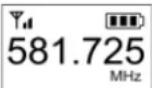 The three digits to the left of the decimal are in millions (MHz).The three digits to the right of the decimal are in thousands (kHz). The three digits to the left of the decimal are in millions (MHz).The three digits to the right of the decimal are in thousands (kHz). | 1 Millions | ▲ increases frequency in increments of 1 MHz per press.▼ decreases frequency in increments of 1 MHz per press. | |
| 2 Thousands | ▲ increases frequency in increments of 25 kHz per press.▼ decreases frequency in increments of 25 kHz per press. | ||
| To save changes:Press SET while thousands is flashing,SAVE is displayed / returns to home screen. | |||
Group setup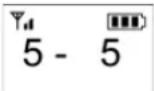 The digit to the left of the (-) is the group numberThe digit(s) to the right of the (-) is the channel number The digit to the left of the (-) is the group numberThe digit(s) to the right of the (-) is the channel number | 3 G: # | ▲ increases the group number (1-8) in increments of one.▼ decreases the group number (1-8) in increments of one. | |
| 4 CH: # | ▲ increases the channel number (up to 22) in increments of one.▼ decreases the channel number (up to 22) in increments of one. | ||
| To save changes:Press SET while channel number is flashing.SAVE is displayed / returns to home screen. | |||
| Sensitivity setupIndication on display:SENSITDisplays current sensitivity setting value | 5 | Ta dB-3 dB | ▲ increases the numeric value in increments of 3dB.▼ decreases the numeric value in increments of 3dB.Setting options (low to high): -15dB,-12dB, -9dB, -6dB, -3dB, 0dB, 3dB,6dB, 9dB, 12dB, 15dB. |
| To save changes:Press SET while displaying sensitivity numeric value.SENSIT is displayed briefly / returns to home screen. | |||
| Sensitivity setup | ▲ increases the numeric value in increments of 3dB. | ||
| Indication on display: SENSIT | 5 | 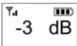 | ▼ decreases the numeric value in increments of 3dB. Setting options (low to high): -15dB, -12dB, -9dB, -6dB, -3dB, 0dB, 3dB, 6dB, 9dB, 12dB, 15dB. |
| Displays current sensitivity setting value | To save changes: Press SET while displaying sensitivity numeric value. SENSIT is displayed briefly / returns to home screen. | ||
| RF Output Power setup | ▲changes low to high.▼changes high to low. | ||
| Indication on display: RF PWR | 6 | High (RFPHI)Will be displayed indicating high RF power. | |
| Low (RFPLo)Will be displayed indicating low RF power. | |||
| NOTE: Does not appear in 8M Band menu routine | To save changes:Press SET while displaying RF power value.SAVE is displayed briefly / returns to home screen. | ||
| Auto Off setup | Use ▲ or ▼ to navigate | |
| Indication on display: | Options are: Off, 1 minute, 10 minutes, and 30 minutes. | |
| AUToF | 7 | Displayed as OFF, 1, 10, or 30. |
| Assigns a time period for the transmitter to automatically turn off once mute is engaged to conserve battery life. | This icon will be displayed indicating an AutoOff timer is set and will begin flashing once transmitter is put into MUTE. | |
| To save changes:Press SET while displaying AutoOFF value.SAVE is displayed briefly / returns to home screen. |
| Key Lock setup | |||
| Indication on display: Loc | To lock the transmitter | Upon entering the Loc screen, pressing ▲ changes OFF to On. | |
| Loc ON | is displayed indicating Keylock is on. | ||
| Keylock prevents unwanted tampering with, or changes to transmitter parameter settings. It can be set up locally on the transmitter, or synced from the receiver in the receiver's Mic Config settings. | 8 | OR | Press SET while displaying Loc On. StorE is displayed / returns to home screen. |
| While pressing and holding ▲, press and hold SET for two seconds to turn lock ON. will be displayed and transmitter is locked. | |||
| To unlock the transmitter | To unlock, press and hold SET until On begins flashing. Pressing ▼ toggles On to OFF. Press SET while displaying LocOFF. StorE is displayed / returns to home screen. | ||
| While pressing and holding ▲, press and hold SET for two | |||
| OR | seconds to turn lock OFF. ⚙ will disappear and transmitter is unlocked. | ||
9 RE3-BPT bodypack transmitter
9.1 Product identification
| ID | Item | Description, usage and notes |
| 1 | Antenna | Flexible antenna. The transmitter will function best when the antenna is oriented vertically (pointing up), exposed to open air, and not in contact with bare skin. |
| 2 | LDC display | Backlit LCD displays all operating information and menus. See display section below for details. |
| 3 | Sync signal port | When syncing the transmitter to the receiver, aim the transmitter's unobstructed sync port directly toward the receiver's sync emitter. A direct line of sight is required. Maintain a distance between two inches and twelve inches (or between 5cm and 30cm) for best sync performance. The blue LED next to the battery alert icon will flash blue during the sync operation an will glow solid blue for three seconds when sync operation is successful. |
| 4 | Battery alert LED | This is a multi-purpose status alert LED: Sync / battery low. Glows solid red when battery low. Flashing blue while syncing. Solid blue for three seconds when the transmitter is successfully sync'd to the receiver. |
| 5 | Power button | This is a multi-purpose button, functioning as a power on and off switch, as well as a menu escape switch.To power ON transmitter: press briefly.To power OFF transmitter: press and hold for three seconds. Transmitter turns off.While in parameter edit mode, press to escape to home screen.CANCEL appears on the screen and no setting changes are saved. |
| 6 | Battery door latch/lock | Slide the latch downward to unlock the battery door. Continue pressing the latch downward while rotating the bottom-hinged door downward to open the battery compartment door. |
| 7 | Battery door | Covers and protects batteries. |
| 8 | Battery compartment | Holds two AA or AA-size rechargeable cells. Install AA cells according to polarity orientation as shown. |
| 9 | SET button | The most commonly used menu navigation button, it is a multi-purpose action button which functions as an enter key, a menu advance key, and a save or store key. |
| 10 | ▲ (up button) | This menu navigation button adjusts the value of an editable parameter. Pressing the ▲ button will increase the displayed value of the current parameter, or the next state condition value above the displayed state value. |
| 11 | ▼ (down button) | This menu navigation button adjusts the value of an editable parameter. Pressing the ▼ button will decrease the displayed value of the current parameter, or the next state condition value below the displayed state value. |
| 12 | Mute switch | This toggle switch engages mute / unmute function, and the colored LED indicates statuses. Sliding the illuminated switch into the mute position silences the audio. Sliding the illuminatedswitch away from mute position makes audio live. LED color indicators:ON = solid green. Mute = flashing red. Low battery = solid red. |
| 13 | Charging contact (one) | Three charging contacts, one to the left side and two on the right are for use when using the optional BC2 battery charger and rechargeable cells. |
| 14 | Charging contacts (two) | Three charging contacts, one to the left side and two on the right are for use when using the optional BC2 battery charger and rechargeable cells. |
| 15 | 4-pin mini jack | This is the audio input jack where the audio input device (lavalier or headworn microphone, or instrument cable) connects to the transmitter. |
| 16 | Belt clip | Using its spring action, this clip secures the transmitter to a belt, waistband, or other stable location. |
9.2 LCD display
| ID | Item | Description, usage and notes |
| a | RF power icon | The RF power indicator is always visible.Υ, indicates RF power is set to low.Υd indicates RF power is set to high (band specific). |
| b | Battery status icon | Indicates battery life.■■■= between 40% and 100% charge remains.■■= between 20% and 39% charge remains.■= between 10% and 19% charge remains.□= below 10% charge remains.bAttLo appears on the display and the empty cell icon begins flashing when batteries are nearing empty. |
| c | Frequency in MHz | The first portion of the tuned frequency to the left of the decimal in millions when the transmitter home screen is set to Freq. Ifscreen is set to display Group/Channel, this screen area will display current group number. |
| d | Frequency in kHz | The second portion of the tuned frequency to the right of the decimal in thousands when the transmitter home screen is set to Freq. If screen is set to display Group/Channel, this screen area will display current channel number. |
| e | Keylock icon | Indicates transmitter is in lock mode. |
| f | MHz | Image is visible the transmitter home screen is set to Freq. Image does not appear when the transmitter home screen is set to Group/Channel. |
| g | AutoOff icon | This icon indicates auto off is engaged. It begins flashing when the transmitter is muted indicating the countdown to shutoff has begun. |
| h | Mute icon | The display shows MUTE only when the transmitter is muted. |
9.3 Installing batteries
- Gently press the sliding magnetic battery door latch (item 6 shown above) downward to unlock, while at the same time rotating the hinged battery door (item 8 shown above) downward to fully open the battery compartment.
- Install two fresh, high quality AA alkaline batteries (or fully charged AA size NiMH rechargeable cells) paying close attention to match the polarity markings (+ and -) on each battery to the polarity markings (+ and -) on the battery contacts.
- Rotate the hinged battery door upward until the compartment door latches shut. The magnetic latch will lock the compartment door.
9.4 RE3-BPT Setup Menu
Editing any of the following parameters locally on the transmitter is possible. These edits will override the settings synced from the mated receiver. Additionally, any parameter value changes made locally on the transmitter may be overwritten the next time the transmitter is synced to the mated receiver if those parameters are selected in the receiver's sync configuration.
NOTE: No local edits will be possible if the transmitter is in Keylock mode (lock icon displayed). See unlocking instructions below.
NOTE: Press and hold SET for three seconds to enter parameter edit mode. The frequency in millions will begin flashing. Once in parameter edit mode, pressing SET multiple times will advance through the adjustable parameters one parameter per press. The press and hold of SET to enter parameter edit mode counts as the first SET button press.
| Function | # of SET button presses | Result | |
Frequency setup The three digits to the left of the decimal are in millions (MHz).The three digits to the right of the decimal are in thousands (kHz). The three digits to the left of the decimal are in millions (MHz).The three digits to the right of the decimal are in thousands (kHz). | 1 Millions | ▲ increases frequency in increments of 1 MHz per press.▼ decreases frequency in increments of 1 MHz per press. | |
| 2 Thousands | ▲ increases frequency in increments of 25 kHz per press.▼ decreases frequency in increments of 25 kHz per press. | ||
| To save changes:Press SET while thousands is flashing.StorE is displayed / returns to home screen. | |||
Group / Channel setup The digit to the left of the (-) is the group numberThe digit(s) to the right of the (-) is the channel number The digit to the left of the (-) is the group numberThe digit(s) to the right of the (-) is the channel number | 3 G: # | ▲ increases the group number (1-8) in single digit increments.▼ decreases the group number (1-8) in single digit increments. | |
| 4 CH: # | ▲ increases the channel number (up to 22) in single digit increments.▼ decreases the channel number (up to 22) in increments of one. | ||
| To save changes:Press SET while channel number is flashing.StorE is displayed / returns to home screen. | |||
| Sensitivity setupIndication on display:SEnSitDisplays current sensitivity setting value | 5 | -6 db | ▲ increases the numeric value in increments of 3dB.▼ decreases the numeric value in increments of 3dB.Setting options (low to high): -15dB, -12dB, -9dB, -6dB, -3dB, 0dB, 3dB, 6dB, 9dB, 12dB, 15dB. |
| To save changes:Press SET while displaying sensitivity numeric value.SENSIT is displayed briefly / returns to home screen. | |||
| Sensitivity setup | ▲ increases the numeric value in increments of 3dB. | ||
| Indication on display: | ▼ decreases the numeric value in increments of 3dB. | ||
| SEnSit | 5 |  | Setting options (low to high): -15dB, -12dB, -9dB, -6dB, -3dB, 0dB, 3dB, 6dB, 9dB, 12dB, 15dB. |
| Displays current sensitivity setting value | |||
| To save changes:Press SET while displaying sensitivity numeric value.SENSIT is displayed briefly / returns to home screen. | |||
| Attenuation setup | |||
| Indication on display: Att | 6 |  | ▲ changes OFF to On, applying 20dB attenuation. |
| When attenuation is set to on, the transmitter audio input stage is attenuated by 20dB. |  | ▼ changes On to OFF. | |
| To save changes:Press SET to store the attenuation status value.StorE is displayed / returns to home screen. | |||
| RF Output Power setup | |||
| Indication on display: rFP | 7 | ▲ changes low to high.▼ changes high to low. | |
 | Low (rFP Lo)▼will appear on the display indicating low RF power. | ||
| NOTE: Does not appear in 8M Band menu routine. |  | High (rFP Hi)▼will appear on the display indicating high RF power. | |
| To save changes:Press SET while displaying RF power value.StorE is displayed briefly / returns to home screen. | |||
| Auto Off setup | |||
| Indication on display: AutoOF | 8 | Use ▲ or ▼ to navigate. | |
| Options are: Off, 1 minute, 10 minutes, and 30 minutes. | |||
| Displayed as OFF, 1, 10, or 30. | |||
| Assigns a time period for the transmitter to automatically turn off once mute is engaged to conserve battery life. | 1 | This icon will be displayed indicating AutoOff timer is set and will begin flashing once when is put into MUTE | |
| To save changes:Press SET while displaying AutoOFF value.StorE is displayed briefly / returns to home screen. | |||
| Key Lock setup | |||
| Indication on display: Loc | 9 | To lock the transmitter | Upon entering the Loc screen, pressing ▲ changes OFF to On.◇ is displayed indicating Keylock is on.Press SET while displaying Loc On.StorE is displayed / returns to home screen. |
| Keylock prevents unwanted tampering | |||
with, or changes to transmitter parameter settings. It can be set up locally on the transmitter, or synced from the receiver in the receiver's Mic Config settings.
| OR | While pressing and holding ▲, press and hold SET for two seconds to turn lock ON. 🔒 is displayed and the transmitter is locked. |
| To unlock the transmitter | To unlock, press and hold SET until On begins flashing. Pressing ▼ toggles On to OFF. Press SET while displaying LocOFF. StorE is displayed / returns to home screen. |
| OR | While pressing and holding ▲, press and hold SET for two seconds to turn lock OFF. 🔒 will disappear and transmitter is unlocked. |
10 Accessories for RE3
Additional transmitters
| RE3-HHT76 | RE3 Handheld transmitter with ND76 head |
| RE3-HHT86 | RE3 Handheld transmitter with ND86 head |
| RE3-HHT96 | RE3 Handheld transmitter with ND96 head |
| RE3-HHT420 | RE3 Handheld transmitter with RE420 head |
| RE3-HHT520 | RE3 Handheld transmitter with RE520 head |
| RE3-BPT | RE3 Bodypack transmitter |
Extra receiver
| RE3-RX | RE3 1/2-space receiver with power supply |
Antenna distribution
| RE3-ACC-AASP | Active antenna splitter, 2-in, 8-out |
| RE3-ACC-PASP | Passive splitter kit |
Extension antennas and boosters
| RE3-ACC-PLPA | Passive log periodic antenna |
| RE3-ACC-ALPA | Active log periodic antenna |
| RE3-ACC-RFAMP | Active RF antenna booster |
Rack mounting
| RE3-ACC-RMK1 | Rack mount kit for single RE3 receiver |
| RE3-ACC-RMK2 | Rack mount kit for two RE3 receivers |
Handheld transmitter microphone heads
| ND76-RC3 | Wireless head with ND76 capsule |
| ND86-RC3 | Wireless head with ND86 capsule |
| ND96-RC3 | Wireless head with ND96 capsule |
| RE420-RC3 | Wireless head with RE420 capsule |
| RE520-RC3 | Wireless head with RE520 capsule |
Handheld transmitter accessory
| RE3-ACC-HHTSA1 | Stand adapter for RE3-HHT transmitter |
RE3 series bodypack transmitter input devices
| RE3-ACC-OL3 | Omnidirectional lavalier mic with 4-pin mini plug |
| RE3-ACC-CL3 | Cardioid lavalier mic with 4-pin mini plug |
| RE3-ACC-HW3 | Headworn mic with 4-pin mini plug |
| RE3-ACC-GC3 | Instrument cable; 1/4" to 4-pin mini plug |
Compatible EV and TELEX bodypack transmitter input devices
| OLM10 | Omnidirectional lavalier condenser mic with 4-pin mini plug |
| ULM18 | Uni-Directional Lapel Mic |
| ULM21 | Cardioid lavalier condenser mic with 4-pin mini plug |
| RE92TX | Premium cardioid lapel microphone with 4-pin mini plug |
| RE97LTX-BEIGE | Miniature omnidirectional lapel microphone with 4-pin mini plug, beige |
| RE97LTX-BLACK | Miniature omnidirectional lapel microphone with 4-pin mini plug, black |
| RE920TX | Premium cardioid instrument mic with a custom shock mounting clip and 4-pin mini plug |
| RE97TX-BEIGE | Omnidirectional low profile headworn microphone in light beige color with 4-pin mini plug |
| RE97TX-BLACK | Omnidirectional low profile headworn microphone in black color with 4-pin mini plug |
| RE97-2TX-BEIGE | Omnidirectional low profile, double ear headworn microphone with 4-pin mini plug |
| HM2 | Headworn cardioid condenser vocal mic with 4-pin mini plug |
| HM3 | Omnidirectional headworn Mic |
| HM7 | Headworn cardioid condenser vocal mic with 4-pin mini plug |
| WPHS-746 | Headworn condenser vocal mic with 4-pin mini plug. Waterproofing material covers mic and headband |
| PH-21 | Headworn, cardioid condenser mic with 4-pin mini plug |
| WLM-50 | Omni-directional electret lapel mic with 4-pin mini plug |
| MAC-G3 | Guitar cord featuring George L's cable with 4-pin mini plug |
Antenna cables
| RE3-ACC-CXUF | Rear to front mount antenna cable kit |
| RE3-ACC-CXU2 | 2 foot antenna coax cable (pair) |
| RE3-ACC-CXU10 | 10 foot, 50 ohm BNC coax cable (pair) |
| RE3-ACC-CXU25 | 25 foot, 50 ohm low loss BNC coax cable |
| RE3-ACC-CXU50 | 50 foot, 50 ohm low loss BNC coax cable |
| RE3-ACC-CXU75 | 75 foot, 50 ohm low loss BNC coax cable |
| RE3-ACC-CXU100 | 100 foot, 50 ohm low loss BNC coax cable |
Battery charging
| RE3-ACC-BC2 | 2-up battery charger. Charges one or two transmitters with rechargeable cells at a time. |
11 Troubleshooting and FAQ
11.1 Troubleshooting
| Unpredictable battery consumption. | Poor quality or stale batteries. | Fresh battery life should be >8 hours. Use fresh, good quality alkaline batteries for longest battery life. Transmitter output power will affect battery consumption as high power setting uses more current. |
| Receiver will not turn on. | Power supply not plugged in. | Ensure power supply is plugged into AC power, and its DC connector is fully plugged into receiver DC input jack. |
| DC power distribution cable from AASP splitter not properly connected (if used). | Ensure DC distribution cable is fully plugged into receiver DC input jack and the other end is fully plugged into an AASP DC output jack. | |
| AC mains circuit is off. | Ensure AC circuit is live by testing another AC powered item. If necessary, locate and reset circuit breaker. | |
| Power button may be damaged. | The RE3 receiver power button is robust and durable, and is unlikely to fail. If other listed resolutions do not solve the problem contact your local Electro-Voice service center. | |
| Transmitter will not turn on. | Dead batteries. | Replace with fresh, high-quality alkaline batteries. |
| Battery polarity reversed. | Ensure battery + and - ends are in contact with the like-marked battery compartment contacts. | |
| Power button may be damaged. | RE3 transmitter power buttons are robust and durable, and are unlikely to fail. If properly-inserted and known-to-be-fresh batteries will still not turn on transmitter, contact your local Electro-Voice service center. | |
| Symptom | Possible cause | Possible resolution |
| Short transmission range. | Transmit power too low. | Set transmitter power to high setting. |
| Receiver squelch set too high. | Adjust receiver squelch by trying lower number values until desired range is achieved. | |
| Improperly placed receiver antennas. | Place receiver antennas out in the open in the shared space of the transmitter away from reflective or grounding surfaces. | |
| Disconnected, incorrect, or failed antenna cable. | Ensure a known-to-be functional and appropriate 50Ω BNC-terminated cable is fully connected at the antenna and receiver. | |
| Competing RF signal at the receiver. | Turn off the transmitter and observe the receiver RF meter. If any RF is showing, follow the scan process and select a new clear frequency. Then turn on the transmitter and resync it to the receiver's new data. | |
| Low AF signal on receiver meter. | Transmitter sensitivity set too low. | Adjust transmitter sensitivity so that high vocal peaks light the yellow LED segment. Under extremely loud vocal peaks, an occasional red LED segment light is OK, but a solid and constant red LED should be avoided. |
| Unstable radio reception. | Radio interference. | Turn off the RE3 transmitter and observe the receiver RF meter. If any RF is showing, follow the scan process and select a clear frequency. Then turn on the transmitter and resync it to the receiver's new data. |
| Improperly placed receiver antennas. | Place receiver antennas out in the open in the shared space of the transmitter away from reflective or grounding surfaces. | |
| Disconnected, incorrect, or failed antenna cable. | Ensure known-to-be functional and appropriate 50Ω BNC-terminated cables are fully connected at the antenna and receiver. | |
| Symptom | Possible cause | Possible resolution |
| Audible dropouts. | Intermittent signal connection at transmitter. | Check for fully connected microphone head or bodypack input device. Ensure proper connection. Determine if a short is causing dropout by shaking cable or manipulating the mic head connection. Use functioning input signal device. |
| Intermittent receiver output signal. | Check for fully functioning audio output cable between receiver and sound system input. Test cable by manipulating it at either end near connectors. Replace cable if shorted or intermittent. | |
| Radio interference. | Turn off the transmitter and observe the receiver RF meter. If any RF is showing, follow the scan process and select a clear frequency. Then turn on the transmitter and resync it to the receiver's new data. | |
| Receiver squelch set too high. | Adjust receiver squelch by trying lower number values until stable audio is achieved. | |
| Improperly placed receiver antennas. | Place receiver antennas out in the open in the shared space of the transmitter away from reflective or grounding surfaces. | |
| Receiver display always shows same antenna (A or B) received. | Disconnected antenna. | Check and correct both antenna connections at receiver and antenna jacks. |
| Improperly placed receiver antennas. | Place receiver antennas out in the open in the shared space of the transmitter away from reflective or grounding surfaces. | |
| Disconnected, incorrect, or failed antenna cable. | Ensure a known-to-be functional and appropriate 50Ω BNC-terminated cable is fully connected at the antenna and receiver. | |
| Receiver display shows no antenna. | No synced transmitter on the frequency. | Turn on transmitter and ensure proper sync to receiver. |
| No antennas connected. | Properly connect antennas as system configuration requires. | |
| Active booster or antenna not receiving DC power (if used). | Turn on antenna DC power at receiver or AASP splitter. | |
| Receiver RF meter shows no RF. | No transmitter turned on or synced. | Turn on synced transmitter. If not synced, follow sync process. |
| Antennas not connected. | Ensure both antennas are properly connected. | |
| Active booster or antenna not receiving DC power (if used). | Turn on antenna DC power at receiver or AASP splitter. | |
| Antenna splitter turned off (if used). | Ensure AASP antenna splitter is turned on. | |
| Receiver RF meter shows RF signal even when synced transmitter is off. | Another RF source is active and generating RF on that frequency which will affect system performance, range, and contribute to possible dropouts. | With the RE3 transmitter off, follow the scan process and select a new clear frequency. Then turn on the transmitter and resync it to the receiver's new data. |
| Low RF signal when using remote antennas. | Improper antenna selection. | Choose an antenna designed for the remote antenna application such as the optional PLPA or ALPA log periodic, or RFAMP booster with the receiver's stock 1/2 wave antenna attached. |
| Improper cable selection. | A long cable run requires low loss cable made for the application. | |
| Improper antenna placement. | Antennas should be placed out in the open, preferably in the space where the transmitter is, and not near or touching reflective or grounding materials. | |
| DC booster feed not on for active antenna or booster. | Make sure the receiver or AASP splitter antenna power is turned on. | |
| Transmit power may be too low for needed range. | Set transmitter power to high (if equipped). | |
| Symptom | Possible cause | Possible resolution |
| Transmitter will not sync to receiver. | Transmitter and receiver may not be in the same frequency band. | Ensure transmitter is the same frequency band as the receiver. |
| Obstructed sync port or sync emitter. | Ensure that the receiver sync emitter and transmitter sync port are not obstructed and clear of debris. Clear obstruction or debris if required. | |
| Direct line of sight between sync emitter and sync port is obstructed. | Ensure clear line of sight between receiver sync emitter and the transmitter sync port. Aim port directly at emitter. | |
| Transmitter sync port out of range with receiver sync emitter. | Maintain recommended range of 2-12 inches between receiver sync emitter and the transmitter sync port. | |
| Receiver display shows NoSYNC. | Synced transmitter is either off or has not been synced. | Turn on synced transmitter. If not synced, follow sync process. |
| Receiver display shows mute. | Synced transmitter is in mute. | Unmute transmitter when necessary. |
| Sound system input not receiving high enough signal. | Receiver audio output level too low. | Use receiver up arrow button to adjust output gain to desired level for sound system input. |
| Sound system input receiving too much gain. | Receiver audio output level too high. | Use receiver down arrow button to adjust output gain to desired level for sound system input. |
11.2 Frequently Asked Questions
Q - Why was my system working fine at sound check, then suddenly it started getting interference during the performance?
A – Using RF wireless can be quite tricky. Sources of competitive RF are everywhere, and they can appear unpredictably. A competing RF signal that wasn’t present during your sound check probably went active during the show. This could be another member of the wireless microphone community in the venue that was off during sound check – possibly another performer’s wireless rig was turned on during your show, and now is interfering with your system. The source could also be a computer (CPU) positioned near the receiver or antennas that wasn’t on earlier. It could even be as pesky as a cell phone near either the transmitter or receiver, which while not being used for a call, is sending GPS signals
periodically, emitting a signal (if close enough to the transmitter or receiver) which could be creating sporadic audible interference. To resolve, rescan the receiver and select a new clear frequency. Then resync the transmitter to the new receiver data.
Q - It seems that when the performer walks way out into the audience, the system starts losing signal. Why am I not getting the range from the system I need?
A – This could indicate a variety of influencing factors. The first thing to check is if your system is, or is not, sharing a frequency with another signal at the receiver. While observing the receiver's RF meter, turn off the transmitter. If the RF meter continues to show signal after the transmitter is off, your transmitter is competing with another signal at the receiver. To solve, perform the scan process, tune the receiver to a new clear frequency, then turn on and sync the transmitter to the new receiver data. The second thing to check is receiver antenna placement and cables. Ensure that your antennas are out in the open in the shared space of the transmitter (meaning not behind walls or in another room), away from reflective or grounding surfaces, and connected to the receiver with appropriately-rated 50Ω BNC-terminated coax cable. The third thing to check is the receiver squelch. Many times, having the squelch set too high will greatly reduce system range. Try lowering the squelch (number value) to increase system range. The fourth thing to check is transmitter output power. If a compromised range is accompanied with low RF signal on the receiver's RF meter, set the transmitter output power to high, then look for improved range.
Q - Why is it hard to find an open frequency in my location?
A – RE3 shares the UHF radio spectrum primarily with UHF television broadcasters. Geographically, some broadcast areas are more densely packed with television broadcast signals than others. A full system scan looks through the entire tuning bandwidth of the receiver and will locate frequencies which are not affected by UHF television or other RF signals. Knowing your local RF environment is important. Those local television stations which broadcast their strong and wide signals into the air are regulated by the government, and consulting government databases will help identify the frequency areas occupied by local broadcasters. RE3 tuning bandwidths are relatively wide, allowing generous tuning options, however if the airwaves aligning with your particular RE3 tuning bandwidth are filled up with UHF television, finding open frequencies will be difficult. Selecting the best band for your area is important. Something to consider is if you are using your RE3 set in the USA or Canada, the 6M band will have no competing UHF television signals because 653-663MHz is designated for wireless microphones only as a result of the reallocation of 600MHz initiatives.
Q - I manually created frequencies for my multi-channel system. Why am I getting interference between the channels?
A – Manually creating custom tuning schemes without the assistance of frequency coordination software may contribute to the problem described. RE3 frequency groups are strategically created to be intermodulation free using advanced frequency coordination software. It’s likely that your self-made grouping has created destructive intermodulation
artifacts which would be avoided by staying with our factory groups. Use RE3 factory groupings. They work well.
Q - Why doesn't the extra RE3 transmitter I bought online work with my RE3 set?
A – The set you originally purchased was pre-configured with a matching transmitter and receiver, which both operate in the same frequency band (5L, 5H, 6M, etc.). If you add another transmitter, it has to be of the same frequency band to work. As this particular question is about additional transmitters, it should be pointed out that adding a second transmitter to an existing set with plans to use both transmitters at the same time with the one existing receiver will not work. At any given time, one of the two transmitters tuned to the receiver's frequency must be off. If they are both on and the same time, substantial interference will occur.
Q - Will the lavalier microphone I have with my older RE-2 system work with RE3?
A – Yes. Legacy Electro-Voice bodypack transmitter input devices with 4-pin mini connectors are compatible with RE3.
Q – I want to put together an eight-channel RE3 system with two remote antennas on the stage feeding the receiver rack. What do I need?
A – First, choose the frequency band or bands your system will be operating in. Based on your location, you'll need to evaluate available spectrum and how it aligns with the RE3 band options. Knowing that information, one option would be to select the same band for all eight sets. Another option is to split the eight by selecting four sets from one band, and the other four from another band, thereby allowing room to compensate for unforeseen changes. You'll probably be rack mounting your receivers, so you'll need four RMK2 dual rack mount kits, which will mount the eight receivers in four rack spaces. You'll need two AASP active antenna splitters which will cascade the RF from two antennas into the eight receivers. You'll need either two PLPA passive log periodic antennas, or two ALPA active log periodic antennas on stage. They will mount on standard microphone stands. Choosing between the two will be influenced by coverage area and the length of antenna cable between antenna and receiver rack. The PLPA, although passive, has 10dB of passive gain, and may be fine if the receiver rack is on stage, however the ALPA active antenna has adjustable gain (selectable 3dB and 10dB amplified), and if the cable run to the receiver rack is lengthy, it may be the best choice. You decide. You'll need TWO low-loss coax cables to run the antenna signals to the first AASP splitter. Choices are RE3-ACC-CXU25 twenty-five foot, RE3-ACC-CXU50 fifty foot, RE3-ACC-CXU75 seventy-five foot, or RE3-ACC-CXU100 one hundred foot. The splitter has all cables required if you connect your remote antenna cables to the rear of the first AASP, but if you want to attach the antenna cables at the front of the rack, you'll need to add an RE3-ACC-CXUF rear to front mount antenna cable kit. That should do it.
Q - Why am I not seeing much audio level on my receiver AF meter?
A – The transmitter input sensitivity likely needs to be adjusted. It has 30dB of adjustment (-15dB at lowest gain to +15dB at highest gain). On the transmitter, press and hold SET until the characters on the display begin to flash. Continue to progressively press SET until reaching the sensitivity parameter. Press the up button to increase the displayed value. Pressing SET will store the new setting. Continue working with this setting until the receiver's AF meter yellow LED is lighting upon high voice peaks. An occasional red LED will be OK.
Q - My receiver is in lock mode. How do I unlock it?
A – Press and hold the SET button for two seconds then use down button to select OFF. Then press SET. Receiver is unlocked.
Q – Why does my receiver RF meter show RF signal present before I turn on the mated transmitter?
A – There is a competing RF signal now present on that frequency. With the RE3 transmitter off, follow the scan process and select a new clear frequency. Then turn on the transmitter and resync it to the receiver's new data.
Q – The frequency I've had my set tuned to has always worked flawlessly. Why is it that when I traveled to an out-of-town gig, I'm getting interference there?
A – RF environments change city-to-city. When traveling, it's important to remember that UHF television broadcasts are not always on the same channel in every city. Something in the city or venue you traveled to is different. Follow the scan process and select a new clear frequency. Then turn on the transmitter and resync it to the receiver's new data.
Q – Our RE3 systems have been working fine in the small venue we play. We decided to try high power on the lead vocal mic transmitter, and now we're having all kinds of problems. What could be wrong?
A – In your small venue, high output power on any or all of your mics may be too much because of transmitter-to-transmitter, and transmitter-to-receiver proximity. Too much RF gain can actually be more destructive than low RF gain. High RF gain is most useful for long transmission distances, but at short distances, it may contribute to intermodulation with nearby transmitters and receivers. If the low power setting was working for you, switch back to it.
Q - I have a long distance between where I want my antennas mounted and where the receivers will be located. Do I need antenna boosters and high-end coax?
A – This might be a very good idea. The purpose of using antenna boosters and/or active antennas is to compensate for the signal loss incurred by the antenna-to-receiver coax cable run. The system you describe will be improved with active RF antenna components and low-loss coax. Coax cable performance is measured by loss factors, i.e., dB of loss per 100 meters. The goal is to deliver to the receiver the approximate RF gain which is received at the antenna. The RE3 optional antenna coax cables should perform as per: 25-foot
CXU25 will lose approximately 1.3 dB on the run, the 50-foot CXU50 will lose approximately 1.4 dB on the run, the 75-foot CXU75 will lose approximately 2.4 dB on the run, and the 100-foot CXU100 will lose approximately 4.4 dB on the run. Factoring in the gains of the antennas, the passive log periodic PLPA is +10 dB, the active log periodic ALPA is either +3 dB or +10 dB (selectable), and the active booster RFAMP is +10 dB. So for example, if your antenna cable run is 100 feet, and you deploy ALPA (set to +10 dB) followed by CXU100 (-4.4 dB), the net RF gain at the receiver is approximately +5.6 dB, which is fine. A handy way to think of it is booster/antenna gain minus cable loss equals net received RF gain. We should also emphasize that an RF boosting device should precede the loss, not make up for it after the loss (place a booster at the antenna location, and not the receiver location).
Q - I'm using an RE3 bodypack wireless for my bass guitar with active pickups and I'm blasting the receiver hard. What could be wrong?
A – Your bodypack transmitter input pad should be engaged. Locate the -20 dB attenuator setting in the menu and set it to ON. If further transmitter audio signal gain reduction is necessary, locate the sensitivity setting in the menu and bring the sensitivity down a few dB as well.
12 Technical data
RE3-RX receiver
| Frequency Oscillation Mode: | Phase-locked loop (PLL) |
| Carrier Frequency Range: | 470 - 865 MHz(tuning bandwidth is band dependent) |
| Band NamesTuning Bandwidths and Carrier Frequency Ranges | 5L: 36 MHz (488-524 MHz)5H: 36 MHz (560-596 MHz)6M: 10 MHz (653-663 MHz)T: 3 MHz (803-806 MHz)8M: (823-865 MHz)8M is split into two segments:9 MHz (823-832 MHz)2 MHz (863-865 MHz) |
| Sync Frequency: | Ultrasonic 40 kHz |
| Diversity: | Antenna diversity |
| Bandwidth: | 36MHz |
| Signal/Noise Ratio: | >100dB(A) |
| Total Harmonic Distortion (Thd): | <0.6%@1kHz |
| Receiving Sensitivity: | -81dBm for -12dB SINAD |
| Frequency Response: | 63Hz~16kHz±2dB (BPT)51Hz~16kHz±2dB (HHT) |
| Antenna Type: | Detachable 1⁄2 wave with BNC connector |
| Antenna Booster Power: | DC12 - 15V/100mA |
| Function Display By: | LCD |
| Contents Of Display: | Group, channel, frequency, antenna A/B, transmitter battery level, transmitter status (mute, live, or no sync), output level attenuation, AF indication, RF indication, lock indicator. |
| Control Functions: | Power, scan, frequency, group, channel, squelch, TX sensitivity, TX attenuation, TX RF power, TX auto off, TX key lock, TX display info, TX sync configuration, RX output volume, RX output level, RX antenna booster power, RX key lock, RX display contrast, RX display brightness, RX system reset. |
| Sync Data Options: | Frequency, group, channel, sensitivity level, attenuation status, RF power, auto off status, key lock status, transmitter display (freq or Gp/Ch) |
| Audio Frequency Output Level: | 14" (6.3mm) Phone Jack -10dBV XLR Jack : -4dBV (Line) & -24dBV (MIC) |
| Audio Frequency Output Impedance: | 240Ω (unbalanced)1400Ω (balanced) |
| Squelch and noise muting: | Noise muting and tone code locking |
| Output Ports: | 1 x balanced XLRM jack1 x unbalanced 14" TS (6.3mm) jack |
| Power Supply: | DC12~15V/500mA |
| Finish: | Black polyurethane paint |
| Dimensions: | Width: 8.27 inch (210mm)Height: (with feet attached) 1.85 inch (47mm)Height: (without feet attached) 1.73 inch (44mm)Depth: (including antenna jack) 6.89 inch (175mm)Depth: (not including antenna jack) 6.1 inch (155mm) |
RE3-HHT handheld transmitter
| Frequency Oscillation Mode: | Phase-locked loop (PLL) |
| Band Names Tuning Bandwidths and Carrier Frequency Ranges | 5L: 36 MHz (488-524 MHz)5H: 36 MHz (560-596 MHz)6M: 10 MHz (653-663 MHz)T: 3 MHz (803-806 MHz)8M: (823-865 MHz)8M is split into two segments:9 MHz (823-832 MHz)2 MHz (863-865 MHz) |
| Sync Frequency: | Ultrasonic |
| RF Power Output: | Frequency band specific as shown below5L (488-524MHz): Low 10mW / High 50mW5H (560-596MHz): Low 10mW / High 50mW6M (653-663MHz): Low 10mW / High 20mWT (803-806MHz): Low 10mW / High 50mW8M (823-865MHz): 10mW |
| Display By: | LCD + LED |
| Function Controls: | Power, mute, group, channel, frequency, sensitivity adjustment, RF power, auto off, key lock. |
| RF Stability: | <±10kHz@Fc |
| Modulation Frequency Shift: | Wideband FM±48kHz deviation |
| Harmonic Radiation: | <-50dBc |
| Battery: | 2 x AA alkaline battery or NiMH rechargeable battery |
| Charging Contacts: | Yes |
| Microphone Head Coupling: | 1.25" diameter, 28 UN-2A thread pitch |
| Microphone Electrical Contact: | 3-ring/3-pin |
| Finish: | Black polyurethane paint |
| Dimensions (without head): | Height: 7.52 inch (191mm)Width at threaded end: 1.46 inch (37mm)Width at control cover: 0.856 inch (22mm) |
RE3-BPT bodypack transmitter
| Frequency Oscillation Mode: | Phase-locked loop (PLL) |
| Band Names:Tuning Bandwidths and Carrier Frequency Ranges: | 5L: 36 MHz (488-524 MHz)5H: 36 MHz (560-596 MHz)6M: 10 MHz (653-663 MHz)T: 3 MHz (803-806 MHz)8M: (823-865 MHz)8M is split into two segments:9 MHz (823-832 MHz)2 MHz (863-865 MHz) |
| Sync Frequency: | Ultrasonic |
| RF Power Output: | Frequency band specific as shown below5L (488-524MHz): Low 10mW / High 50mW5H (560-596MHz): Low 10mW / High 50mW6M (653-663MHz): Low 10mW / High 20mWT (803-806MHz): Low 10mW / High 50mW8M (823-865MHz): 10mW |
| Display By: | LCD + LED |
| Function Controls: | Power, mute, group, channel, frequency, sensitivity adjustment, input level attenuation, RF power, auto off kev lock. |
| RF Stability: | <±10kHz@Fc |
| Modulation Frequency Shift: | Wideband FM±48kHz deviation |
| Harmonic Radiation: | <-50dBc |
| Input Jack: | 4-pin mini jack |
| Battery: | 2 x AA alkaline battery or NiMH rechargeable battery |
| Charging contacts: | Yes |
| Dimensions (without antenna): | Height: 3.2 inch (81.5mm)Width: 2.54 inch (64.5mm)Depth: 0.98 inch (25mm) |
RE3-OL3 omnidirectional lavalier
| Element Type: | Self-biased Condenser |
| Frequency Response: | 60Hz - 15 kHz |
| Polar Pattern: | Omnidirectional |
| Sensitivity: Open Circuit Voltage.17.5mV/Pascal | |
| 1 kHz: | (-35 dBV/PA) |
| Maximum SPL: | 130dB SPL |
| Impedance: | 2200 ohms |
| Power Requirements: | 3-9 VDC |
| Polarity: | Positive pressure on diaphragm produces positive voltage at pin 2 relative to pin 1 |
| Electrical Contact Pinouts: | Pin #1 - Ground, ShieldPin #2 - AudioPin #3 - Bias Voltage |
| Dimensions (Cable length) : | 57.1" [1450mm] |
| Dimensions (Head length) : | 0.36" [9.2mm] |
| Dimensions (Head diameter) : | 0.2" [5mm] |
| Microphone Connector: | 4-pin mini plug |
| Head Finish: | Non-reflecting Black |
| Material: | Brass, Steel wire cloth grille, Black flexible PVC cable |
RE3-CL3 cardioid lavalier
| Element Type: | Self-biased Condenser |
| Frequency Response: | 100Hz - 15 kHz |
| Polar Pattern: | Cardioid |
| Sensitivity: Open Circuit Voltage. | 20mV/Pascal |
| 1 kHz: | (-34 dBV/PA) |
| Maximum SPL: | 115dB SPL |
| Impedance: | 3700 ohms |
| Power Requirements: | 3-9 VDC |
| Polarity: | Positive pressure on diaphragm produces positive voltage at pin 2 relative to pin 1 |
| Electrical Contact Pinouts: | Pin #1 - Ground, ShieldPin #2 - AudioPin #3 - Bias VoltagePin #4 - N/C |
| Dimensions (Cable length) : | 56.3" [1430mm] |
| Dimensions (Head length) : | 1.04" [26.4mm] |
| Dimensions (Head diameter) : | 0.4" [10.1mm] |
| Microphone Connector: | 4-pin mini plug |
| Head Finish: | Non-reflecting Black |
| Material: | Die cast aluminum, Steel wire cloth grille, Black flexible PVC cable |
RE3-HW3 headworn microphone
| Element Type: Self-biased Condenser | |
| Frequency Response: 30Hz - 18 kHz | |
| Polar Pattern: Supercardioid | |
| Sensitivity: Open Circuit Voltage. 0.5mV/Pascal1 kHz: (-47 dBV/PA) | |
| Maximum SPL: 130dB SPL | |
| Impedance: 1000 ohms | |
| Power Requirements: 3-9 VDC | |
| Polarity: | Positive pressure on diaphragm produces positive voltage at pin 2 relative to pin 1 |
| Electrical Contact Pinouts: | Pin #1 - Ground, ShieldPin #2 - AudioPin #3 - Bias VoltagePin #4 - N/C |
Dimensions (Cable length) : 45.28" [1150mm]
Dimensions (Boom length) :5.83" [148mm]
Microphone Connector: 4-pin mini plug
Head Finish: Non-reflecting Black
| Material: | Black stainless steel painted adjustable headband frame. Molded back facing connector joint with 2.5mm jack for detachable cable, black textured PU. Black painted steel 100mm x 4.5mm flexible mic positing tube. Integrated black TPR mic shock mount. Clear soft silicone tubing at ear contact points. |
RE3-GC3 instrument cable
| Electrical Contact Pinouts: | Pin #1 - Ground, ShieldPin #2 - AudioPin #3 - N/CPin #4 - N/C |
| Connectors: | 6.5mm (1/4 inch) phone plug4-pin mini plug |
| Dimensions, Cable Length with Connectors: | 32.7” (830mm) |
ND76-RC3 dynamic cardioid microphone head
| Element Type: | Dynamic neodymium magnet structure |
| Frequency response, Close: | 30 Hz – 17 kHz |
| Frequency response, Far: | 70 Hz – 17 kHz |
| Polar Pattern: | Cardioid |
| Sensitivity, Open Circuit Voltage @ 1 kHz: | 5.6 mV/Pascal (-45 dBV/Pa) |
| Maximum SPL: | 135.5 dB SPL (1% THD) |
| Power Requirements: | 4-8 VDC |
| Polarity: | Positive pressure on diaphragm produces positive voltage at center contact relative to ground contact |
| Electrical Contact: | 3-Ring / 3-Pin |
| Threaded Coupling: | 1.25” Diameter28 UN-2A Thread Pitch |
| Finish: | Black polyurethane paint |
| Materials: | Aluminum, steel, steel wire grille screen |
| Dimensions, Length: | 3.6 in (91 mm) |
| Diameter: | 2.0 in (50.5 mm) |
ND86-RC3 dynamic supercardioid microphone head
| Element Type: | Dynamic neodymium magnet structure |
| Frequency response, Close: | 30 Hz – 17 kHz |
| Frequency response, Far: | 70 Hz – 17 kHz |
| Polar Pattern: | Supercardioid |
| Sensitivity, Open Circuit Voltage @ 1 kHz: | 5.6 mV/Pascal (-45 dBV/Pa) |
| Maximum SPL: | 134.5 dB SPL (1% THD) |
| Power Requirements: | 4-8 VDC |
| Polarity: | Positive pressure on diaphragm produces positive voltage at center contact relative to ground contact |
| Electrical Contact: | 3-Ring / 3-Pin |
| Threaded Coupling: | 1.25” Diameter28 UN-2A Thread Pitch |
| Finish: | Black polyurethane paint |
| Materials: | Aluminum, steel, steel wire grille screen |
| Dimensions, Length: | 3.6 in (91 mm) |
| Diameter: | 2.0 in (50.5 mm) |
ND96-RC3 dynamic supercardioid microphone head
| Element Type: | Dynamic neodymium magnet structure |
| Frequency response, Close: | 30 Hz – 15 kHz |
| Frequency response, Far: | 140 Hz – 15 kHz |
| Polar Pattern: | Supercardioid |
| Sensitivity, Open Circuit Voltage @ 1 kHz in flat position: | 4.7 mV/Pascal (-46.5 dBV/Pa) |
| Sensitivity, Open Circuit Voltage @ 1 kHz in vocal presence position: | 3.2 mV/Pascal (-50 dBV/Pa) |
| Maximum SPL: | 136.5 dB SPL (1@ THD) |
| Power Requirements: | 4-8 VDC |
| Polarity: | Positive pressure on diaphragm produces positive voltage at center contact relative to ground contact |
| Electrical Contact: | 3-Ring / 3-Pin |
| Threaded Coupling: | 1.25” Diameter28 UN-2A Thread Pitch |
| Finish: | Black polyurethane paint |
| Materials: | Aluminum, steel, steel wire grille screen |
| Dimensions, Length: | 3.3 in (83.5 mm) |
| Diameter: | 2.0 in (50.5 mm) |
RE420-RC3 condenser cardioid microphone head
| Element Type: | Self-biased Condenser |
| Frequency Response: | 50 Hz to 20,000 Hz |
| Polar Pattern: | Cardioid |
| Sensitivity: Open Circuit Voltage. 1 kHz: | 5.6mV/Pascal(-45 dBV/PA) |
| Clipping (max SPL): | 137 dB SPL (1% THD) |
| Self Noise: | 22 dB SPL "A" weighted (0 dB = 20 micropascals) |
| Dynamic Range: | 115 dB |
| Signal-to-Noise Ratio: | 72 dB |
| Power Requirements: | 4-8 VDC |
| Polarity: | Positive pressure on diaphragm produces positive voltage at center contact relative to ground contact |
| Electrical Contact: | 3-Ring / 3-Pin |
| Threaded Coupling: | 1.25” Diameter28 UN-2A Thread Pitch |
| Finish: | Black polyurethane paint |
| Materials: | Aluminum, steel, steel wire grille screen |
Dimensions, Length: 3.36 in (85.3 mm)
Diameter : 1.95 in (49.6 mm)
RE520-RC3 condenser supercardioid microphone head
| Element Type: | Self-biased Condenser |
| Frequency Response: | 40 Hz to 20,000 Hz |
| Polar Pattern: | Supercardioid |
| Sensitivity: Open Circuit Voltage.5.6mV/Pascal | |
| 1 kHz: | (-45 dBV/PA) |
| Clipping (max SPL): | 139 dB SPL (1% THD) |
| Self Noise: | 22 dB SPL "A" weighted (0 dB = 20 micropascals) |
| Dynamic Range: | 117 dB |
| Signal-to-Noise Ratio: | 72 dB |
| Power Requirements: | 4-8 VDC |
| Polarity: | Positive pressure on diaphragm produces positive voltage at center contact relative to ground contact |
| Electrical Contact: | 3-Ring / 3-Pin |
| Threaded Coupling: | 1.25” Diameter28 UN-2A Thread Pitch |
| Finish: | Black polyurethane paint |
| Materials: | Aluminum, steel, steel wire grille screen |
| Dimensions, Length: | 3.36 in (85.3 mm) |
| Diameter: | 1.95 in (49.6 mm) |
13 Frequency Group / Channel Tables
Band 5L (488-524 MHz)
RE3 Frequency Band: 5L 488 - 524 MHz Orients to NTSC TV Channels 17 - 22 PAL TV Channels 23 - 27
| NTSC TV Channel Orientation | NTSC TV Channel Orientation | NTSC TV Channel Orientation | NTSC TV Channel Orientation | ||||||||||||||||
| 17 | 1 | 488.325 | 1 | 23 | 17 | 1 | 488.175 | 1 | 23 | 17 | 1 | 489.625 | 1 | 23 | 17 | 1 | 488.800 | 1 | 23 |
| 2 | 491.200 | 2 | 2 | 489.375 | 2 | 2 | 490.800 | 2 | 2 | 489.650 | 2 | ||||||||
| 3 | 493.450 | 3 | 3 | 491.525 | 3 | 3 | 492.575 | 3 | 3 | 492.125 | 3 | ||||||||
| 18 | 4 | 494.700 | 4 | 24 | 18 | 4 | 494.425 | 4 | 24 | 18 | 4 | 496.600 | 4 | 24 | 18 | 4 | 494.225 | 4 | 24 |
| 5 | 497.450 | 5 | 5 | 495.500 | 5 | 5 | 498.775 | 5 | 5 | 498.075 | 5 | ||||||||
| 19 | 6 | 500.450 | 6 | 6 | 498.000 | 6 | 19 | 6 | 503.275 | 6 | 25 | 19 | 6 | 502.775 | 6 | 25 | |||
| 7 | 504.200 | 7 | 25 | 19 | 7 | 503.750 | 7 | 25 | 20 | 7 | 507.125 | 7 | 7 | 505.400 | 7 | ||||
| 8 | 505.700 | 8 | 8 | 505.500 | 8 | 8 | 508.675 | 8 | 20 | 8 | 507.100 | 8 | |||||||
| 20 | 9 | 510.325 | 9 | 26 | 20 | 9 | 509.750 | 9 | 9 | 511.425 | 9 | 26 | 9 | 511.075 | 9 | 26 | |||
| 21 | 10 | 512.825 | 10 | 21 | 10 | 514.500 | 10 | 26 | 21 | 10 | 516.525 | 10 | 21 | 10 | 512.375 | 10 | |||
| 11 | 514.200 | 11 | 11 | 517.525 | 11 | 22 | 11 | 518.900 | 11 | 27 | 11 | 517.325 | 11 | ||||||
| 22 | 12 | 518.325 | 12 | 27 | 22 | 12 | 518.950 | 12 | 27 | 12 | 519.900 | 12 | 22 | 12 | 520.500 | 12 | 27 | ||
| 13 | 520.700 | 13 | 13 | 521.225 | 13 | 13 | 522.475 | 13 | 13 | 521.525 | 13 | ||||||||
| 14 | 521.700 | 14 | 14 | 522.125 | 14 | 14 | 523.075 | 14 | 14 | 523.400 | 14 | ||||||||
| NTSC | TV Channel Orientation | NTSC | TV Channel Orientation | NTSC | TV Channel Orientation | NTSC | TV Channel Orientation | ||||||||||||
| CH | Group 5 Frequency | CH | PAL | CH | Group 6 Frequency | CH | PAL | CH | Group 7 Frequency | CH | PAL | CH | Group 8 Frequency | CH | PAL | ||||
| 17 | 1 | 488.600 | 1 | 23 | 17 | 1 | 488.525 | 1 | 23 | 17 | 1 | 488.825 | 1 | 23 | 17 | 1 | 489.300 | 1 | 23 |
| 2 | 490.475 | 2 | 2 | 489.525 | 2 | 2 | 489.575 | 2 | 2 | 490.425 | 2 | ||||||||
| 3 | 491.850 | 3 | 3 | 491.400 | 3 | 3 | 491.325 | 3 | 3 | 491.925 | 3 | ||||||||
| 4 | 493.850 | 4 | 4 | 492.775 | 4 | 4 | 491.950 | 4 | 4 | 492.925 | 4 | ||||||||
| 18 | 5 | 495.600 | 5 | 24 | 18 | 5 | 495.775 | 5 | 24 | 18 | 5 | 492.825 | 5 | 24 | 18 | 5 | 495.175 | 5 | 24 |
| 6 | 498.725 | 6 | 6 | 498.400 | 6 | 6 | 494.025 | 6 | 6 | 497.800 | 6 | ||||||||
| 7 | 499.750 | 7 | 7 | 499.975 | 7 | 7 | 495.700 | 7 | 7 | 499.050 | 7 | ||||||||
| 19 | 8 | 502.225 | 8 | 25 | 19 | 8 | 500.650 | 8 | 8 | 498.825 | 8 | 19 | 8 | 501.800 | 8 | ||||
| 9 | 504.100 | 9 | 9 | 502.400 | 9 | 25 | 9 | 500.950 | 9 | 9 | 502.425 | 9 | 25 | ||||||
| 10 | 505.100 | 10 | 10 | 503.800 | 10 | 10 | 502.325 | 10 | 25 | 10 | 504.800 | 10 | |||||||
| 20 | 11 | 506.475 | 11 | 20 | 11 | 506.025 | 11 | 11 | 503.950 | 11 | 20 | 11 | 509.300 | 11 | |||||
| 12 | 509.725 | 12 | 12 | 506.775 | 12 | 20 | 12 | 507.325 | 12 | 12 | 510.175 | 12 | 26 | ||||||
| 21 | 13 | 512.225 | 13 | 26 | 21 | 13 | 510.650 | 13 | 26 | 13 | 508.575 | 13 | 21 | 13 | 512.300 | 13 | |||
| 14 | 513.650 | 14 | 14 | 512.525 | 14 | 14 | 511.275 | 14 | 26 | 14 | 514.675 | 14 | |||||||
| 15 | 516.100 | 15 | 15 | 514.150 | 15 | 21 | 15 | 514.325 | 15 | 15 | 515.800 | 15 | |||||||
| 16 | 516.975 | 16 | 16 | 516.650 | 16 | 16 | 516.375 | 16 | 16 | 517.300 | 16 | ||||||||
| 22 | 17 | 518.150 | 17 | 27 | 22 | 17 | 518.525 | 17 | 27 | 17 | 517.950 | 17 | 22 | 17 | 521.050 | 17 | 27 | ||
| 18 | 518.850 | 18 | 18 | 519.525 | 18 | 22 | 18 | 519.825 | 18 | 27 | 18 | 521.800 | 18 | ||||||
| 19 | 521.350 | 19 | 19 | 521.025 | 19 | 19 | 520.825 | 19 | 19 | 523.175 | 19 | ||||||||
| 20 | 522.850 | 20 | 20 | 521.900 | 20 | 20 | 522.200 | 20 | 20 | 523.925 | 20 | ||||||||
| 21 | 523.475 | 21 | 21 | 523.150 | 21 | 21 | 522.950 | 21 | |||||||||||
| 22 | 523.850 | 22 | 22 | 523.950 | 22 | ||||||||||||||
Band 5H (560-596 MHz)
| NTSC | TV Channel Orientation | PAL | ||
| CH | Group 1 Frequency | CH | ||
| 29 | 1 | 560.325 | 1 | 32 |
| 2 | 563.200 | 2 | ||
| 3 | 565.450 | 3 | ||
| 30 | 4 | 566.700 | 4 | 33 |
| 5 | 569.450 | 5 | ||
| 31 | 6 | 572.450 | 6 | 34 |
| 7 | 576.200 | 7 | ||
| 8 | 577.700 | 8 | ||
| 32 | 9 | 582.325 | 9 | 35 |
| 33 | 10 | 584.825 | 10 | |
| 11 | 586.200 | 11 | ||
| 34 | 12 | 590.325 | 12 | 36 |
| 13 | 592.700 | 13 | ||
| 14 | 593.700 | 14 | ||
| NTSC | TV Channel Orientation | PAL | ||
| Group 2 | ||||
| CH | Frequency | CH | ||
| 29 | 1 | 560.175 | 1 | 32 |
| 2 | 561.375 | 2 | ||
| 3 | 563.525 | 3 | ||
| 30 | 4 | 566.425 | 4 | 33 |
| 5 | 567.500 | 5 | ||
| 6 | 570.000 | 6 | ||
| 31 | 7 | 575.750 | 7 | 34 |
| 8 | 577.500 | 8 | ||
| 32 | 9 | 581.750 | 9 | |
| 33 | 10 | 586.500 | 10 | 35 |
| 11 | 589.525 | 11 | ||
| 34 | 12 | 590.950 | 12 | 36 |
| 13 | 593.225 | 13 | ||
| 14 | 594.125 | 14 | ||
| NTSC TV Channel Orientation | PAL | |||
| NTSC | Group 3 | |||
| CH | Frequency | CH | ||
| 29 | 1 | 561.625 | 1 | 32 |
| 2 | 562.800 | 2 | ||
| 3 | 564.575 | 3 | ||
| 30 | 4 | 568.600 | 4 | 33 |
| 5 | 570.775 | 5 | ||
| 31 | 6 | 575.275 | 6 | 34 |
| 32 | 7 | 579.125 | 7 | |
| 8 | 580.675 | 8 | ||
| 9 | 583.425 | 9 | 35 | |
| 33 | 10 | 588.525 | 10 | |
| 34 | 11 | 590.900 | 11 | 36 |
| 12 | 591.900 | 12 | ||
| 13 | 594.475 | 13 | ||
| 14 | 595.075 | 14 | ||
| NTSC | TV Channel Orientation | PAL | ||
| Group 4 | ||||
| CH | Frequency | CH | ||
| 29 | 1 | 560.800 | 1 | 32 |
| 2 | 561.650 | 2 | ||
| 3 | 564.125 | 3 | ||
| 30 | 4 | 566.225 | 4 | 33 |
| 5 | 570.075 | 5 | ||
| 31 | 6 | 574.775 | 6 | 34 |
| 7 | 577.400 | 7 | ||
| 32 | 8 | 579.100 | 8 | |
| 9 | 583.075 | 9 | 35 | |
| 33 | 10 | 584.375 | 10 | |
| 11 | 589.325 | 11 | ||
| 34 | 12 | 592.500 | 12 | 36 |
| 13 | 593.525 | 13 | ||
| 14 | 595.400 | 14 | ||
| NTSC | TV Channel Orientation | |||
| Group 5 | PAL | |||
| CH | Frequency | CH | ||
| 29 | 1 | 560.600 | 1 | 32 |
| 2 | 562.475 | 2 | ||
| 3 | 563.850 | 3 | ||
| 4 | 565.850 | 4 | ||
| 30 | 5 | 567.600 | 5 | 33 |
| 6 | 570.725 | 6 | ||
| 7 | 571.750 | 7 | ||
| 31 | 8 | 574.225 | 8 | 34 |
| 9 | 576.100 | 9 | ||
| 10 | 577.100 | 10 | ||
| 32 | 11 | 578.475 | 11 | |
| 12 | 581.725 | 12 | ||
| 33 | 13 | 584.225 | 13 | 35 |
| 14 | 585.650 | 14 | ||
| 15 | 588.100 | 15 | ||
| 16 | 588.975 | 16 | ||
| 34 | 17 | 590.150 | 17 | 36 |
| 18 | 590.850 | 18 | ||
| 19 | 593.350 | 19 | ||
| 20 | 594.850 | 20 | ||
| 21 | 595.475 | 21 | ||
| NTSC | TV Channel Orientation | |||
| Group 6 | PAL | |||
| CH | Frequency | CH | ||
| 29 | 1 | 560.525 | 1 | 32 |
| 2 | 561.525 | 2 | ||
| 3 | 563.400 | 3 | ||
| 4 | 564.775 | 4 | ||
| 30 | 5 | 567.775 | 5 | 33 |
| 6 | 570.400 | 6 | ||
| 7 | 571.975 | 7 | ||
| 31 | 8 | 572.650 | 8 | |
| 9 | 574.400 | 9 | 34 | |
| 10 | 575.800 | 10 | ||
| 32 | 11 | 578.025 | 11 | |
| 12 | 578.775 | 12 | ||
| 13 | 582.650 | 13 | 35 | |
| 33 | 14 | 584.525 | 14 | |
| 15 | 586.150 | 15 | ||
| 16 | 588.650 | 16 | ||
| 34 | 17 | 590.525 | 17 | 36 |
| 18 | 591.525 | 18 | ||
| 19 | 593.025 | 19 | ||
| 20 | 593.900 | 20 | ||
| 21 | 595.150 | 21 | ||
| 22 | 595.850 | 22 | ||
| NTSC | TV Channel Orientation | |||
| Group 7 | PAL | |||
| CH | Frequency | CH | ||
| 29 | 1 | 560.825 | 1 | 32 |
| 2 | 561.575 | 2 | ||
| 3 | 563.325 | 3 | ||
| 4 | 563.950 | 4 | ||
| 5 | 564.825 | 5 | ||
| 30 | 6 | 566.025 | 6 | 33 |
| 7 | 567.700 | 7 | ||
| 8 | 570.825 | 8 | ||
| 31 | 9 | 572.950 | 9 | |
| 10 | 574.325 | 10 | 34 | |
| 11 | 575.950 | 11 | ||
| 32 | 12 | 579.325 | 12 | |
| 13 | 580.575 | 13 | ||
| 14 | 583.275 | 14 | ||
| 33 | 15 | 586.325 | 15 | 35 |
| 16 | 588.375 | 16 | ||
| 17 | 589.950 | 17 | ||
| 34 | 18 | 591.825 | 18 | 36 |
| 19 | 592.825 | 19 | ||
| 20 | 594.200 | 20 | ||
| 21 | 594.950 | 21 | ||
| 22 | 595.950 | 22 | ||
| NTSC | TV Channel Orientation | |||
| Group 8 | PAL | |||
| CH | Frequency | CH | ||
| 29 | 1 | 561.300 | 1 | 32 |
| 2 | 562.425 | 2 | ||
| 3 | 563.925 | 3 | ||
| 4 | 564.925 | 4 | ||
| 30 | 5 | 567.175 | 5 | 33 |
| 6 | 569.800 | 6 | ||
| 7 | 571.050 | 7 | ||
| 31 | 8 | 573.800 | 8 | 34 |
| 9 | 574.425 | 9 | ||
| 10 | 576.800 | 10 | ||
| 32 | 11 | 581.300 | 11 | 35 |
| 12 | 582.175 | 12 | ||
| 33 | 13 | 584.300 | 13 | |
| 14 | 586.675 | 14 | ||
| 15 | 587.800 | 15 | ||
| 16 | 589.300 | 16 | ||
| 34 | 17 | 593.050 | 17 | 36 |
| 18 | 593.800 | 18 | ||
| 19 | 595.175 | 19 | ||
| 20 | 595.925 | 20 | ||
Band 6M (653-663 MHz)
RE3 Frequency Band: 6M 653 - 663 MHz
| Required | License Requirement | |
| CH | Group 1 Frequency | |
| Y | 1 | 653.150 |
| Y | 2 | 654.150 |
| Y | 3 | 655.600 |
| Y | 4 | 656.050 |
| Y | 5 | 656.750 |
| N | 6 | 658.325 |
| N | 7 | 660.100 |
| N | 8 | 661.375 |
| N | 9 | 662.250 |
| Required | License Requirement | |
| CH | Group 2 Frequency | |
| Y | 1 | 653.800 |
| Y | 2 | 654.900 |
| Y | 3 | 655.525 |
| Y | 4 | 656.500 |
| N | 5 | 657.775 |
| N | 6 | 658.550 |
| N | 7 | 660.975 |
| N | 8 | 662.400 |
| N | 9 | 662.850 |
Operates within the *North American Duplex Gap
* Portions of this gap require user license as noted
| Required | License Requirement | |
| CH | Group 3 Frequency | |
| Y | 1 | 653.125 |
| Y | 2 | 653.575 |
| Y | 3 | 655.675 |
| N | 4 | 657.000 |
| N | 5 | 657.950 |
| N | 6 | 659.400 |
| N | 7 | 661.050 |
| N | 8 | 662.150 |
| N | 9 | 662.950 |
| Required | License Requirement | |
| CH | Group 4 Frequency | |
| Y | 1 | 653.675 |
| Y | 2 | 654.500 |
| Y | 3 | 655.825 |
| Y | 4 | 656.950 |
| N | 5 | 657.650 |
| N | 6 | 659.975 |
| N | 7 | 660.425 |
| N | 8 | 661.425 |
| N | 9 | 662.000 |
| Required | License Requirement | |
| CH | Group 5 Frequency | |
| Y | 1 | 653.225 |
| Y | 2 | 653.650 |
| Y | 3 | 654.650 |
| Y | 4 | 655.050 |
| Y | 5 | 656.275 |
| N | 6 | 657.325 |
| N | 7 | 659.100 |
| N | 8 | 660.275 |
| N | 9 | 660.675 |
| N | 10 | 661.250 |
| N | 11 | 661.650 |
| N | 12 | 662.800 |
| Required | License Requirement | |
| CH | Group 6 Frequency | |
| Y | 1 | 653.050 |
| Y | 2 | 653.525 |
| Y | 3 | 654.300 |
| Y | 4 | 655.325 |
| Y | 5 | 656.000 |
| Y | 6 | 656.900 |
| N | 7 | 658.000 |
| N | 8 | 659.275 |
| N | 9 | 659.750 |
| N | 10 | 661.125 |
| N | 11 | 662.275 |
| N | 12 | 662.775 |
| Required | License Requirement | |
| CH | Group 7 Frequency | |
| Y | 1 | 653.500 |
| Y | 2 | 654.250 |
| Y | 3 | 655.175 |
| Y | 4 | 655.900 |
| N | 5 | 657.200 |
| N | 6 | 657.725 |
| N | 7 | 658.950 |
| N | 8 | 659.900 |
| N | 9 | 660.525 |
| N | 10 | 661.550 |
| N | 11 | 662.325 |
| N | 12 | 662.925 |
| Required | License Requirement | |
| CH | Group 8 Frequency | |
| Y | 1 | 653.250 |
| Y | 2 | 653.850 |
| Y | 3 | 654.750 |
| Y | 4 | 655.150 |
| Y | 5 | 655.850 |
| N | 6 | 657.450 |
| N | 7 | 658.675 |
| N | 8 | 659.475 |
| N | 9 | 660.800 |
| N | 10 | 661.225 |
| N | 11 | 661.925 |
| N | 12 | 662.425 |
natural_image
Grid of white geometric shapes arranged in a 3x3 pattern on a gray background (no text or symbols)Bosch Security Systems, LLC
12000 Portland Avenue South
Burnsville MN 55337
www.electrovoice.com