DS-MP3516-RS - Audio intercom Hikvision - Free user manual and instructions
Find the device manual for free DS-MP3516-RS Hikvision in PDF.

User questions about DS-MP3516-RS Hikvision
0 question about this device. Answer the ones you know or ask your own.
Ask a new question about this device
Download the instructions for your Audio intercom in PDF format for free! Find your manual DS-MP3516-RS - Hikvision and take your electronic device back in hand. On this page are published all the documents necessary for the use of your device. DS-MP3516-RS by Hikvision.
USER MANUAL DS-MP3516-RS Hikvision
text_image
HIKVISIONRail Network Video Recorder
User Manual
UD.6L0204D1165A01
User Manual
COPYRIGHT © 2016 Hangzhou Hikvision Digital Technology Co., Ltd.
ALL RIGHTS RESERVED.
Any and all informaon, including, among others, wordings, pictures, graphs are the properes of Hangzhou Hikvision Digital Technology Co., Ltd. or its subsidiaries (hereinaer referred to be "Hikvision"). This user manual (hereinaer referred to be "the Manual") cannot be reproduced, changed, translated, or distributed, parally or wholly, by any means, without the prior written permission of Hikvision. Unless otherwise spulated, Hikvision does not make any warranes, guarantees or representaons, express or implied, regarding to the Manual.
About this Manual
This Manual is applicable to Rail NVR (Network Video Recorder).
The Manual includes instrucons for using and managing the product. Pictures, charts, images and all other informaon hereinaer are for descripon and explanaon only. The informaon contained in the Manual is subject to change, without noce, due to rmware updates or other reasons. Please nd the latest version in the company website (hp://overseas.hikvision.com/en/).
Please use this user manual under the guidance of professionals.
Trademarks Acknowledgement
HIKVISION and other Hikvision's trademarks and logos are the properes of Hikvision in various jurisdicons.
Other trademarks and logos menoned below are the properes of their respective owners.
Legal Disclaimer
TO THE MAXIMUM EXTENT PERMITTED BY APPLICABLE LAW, THE PRODUCT DESCRIBED, WITH ITS HARDWARE, SOFTWARE AND FIRMWARE, IS PROVIDED "AS IS", WITH ALL FAULTS AND ERRORS, AND HIKVISION MAKES NO WARRANTIES, EXPRESS OR IMPLIED, INCLUDING WITHOUT LIMITATION, MERCHANTABILITY, SATISFACTORY QUALITY, FITNESS FOR A PARTICULAR PURPOSE, AND NON-INFRINGEMENT OF THIRD PARTY. IN NO EVENT WILL HIKVISION, ITS DIRECTORS, OFFICERS, EMPLOYEES, OR AGENTS BE LIABLE TO YOU FOR ANY SPECIAL, CONSEQUENTIAL, INCIDENTAL, OR INDIRECT DAMAGES, INCLUDING, AMONG OTHERS, DAMAGES FOR LOSS OF BUSINESS PROFITS, BUSINESS INTERRUPTION, OR LOSS OF DATA OR DOCUMENTATION, IN CONNECTION WITH THE USE OF THIS PRODUCT, EVEN IF HIKVISION HAS BEEN ADVISED OF THE POSSIBILITY OF SUCH DAMAGES. REGARDING TO THE PRODUCT WITH INTERNET ACCESS, THE USE OF PRODUCT SHALL BE WHOLLY AT YOUR OWN RISKS. HIKVISION SHALL NOT TAKE ANY RESPONSIBILITES FOR ABNORMAL OPERATION, PRIVACY LEAKAGE OR OTHER DAMAGES RESULTING FROM CYBER ATTACK, HACKER ATTACK, VIRUS INSPECTION, OR OTHER INTERNET SECURITY RISKS; HOWEVER, HIKVISION WILL PROVIDE TIMELY TECHNICAL SUPPORT IF REQUIRED. SURVEILLANCE LAWS VARY BY JURISDICTION. PLEASE CHECK ALL RELEVANT LAWS IN YOUR JURISDICTION BEFORE USING THIS PRODUCT IN ORDER TO ENSURE THAT YOUR USE CONFORMS THE APPLICABLE LAW. HIKVISION SHALL NOT BE LIABLE IN THE EVENT THAT THIS PRODUCT IS USED WITH ILLEGITIMATE PURPOSES. IN THE EVENT OF ANY CONFLICTS BETWEEN THIS MANUAL AND THE APPLICABLE LAW, THE LATER PREVAILS.
Regulatory informaon
FCC informaon
FCC compliance: Please take aenon that changes or modicaon not expressly approved by the party responsible for compliance could void the user's authority to operate the equipment.
Note: This product has been tested and found to comply with the limits for a Class B digital device, pursuant to Part 15 of the FCC Rules. These limits are designed to provide reasonable protecon against harmful interference in a residential installaon. This product generates, uses, and can radiate radio frequency energy and, if not installed and used in accordance with the instrucons, may cause harmful interference to radio communicaons. However, there is no guarantee that interference will not occur in a parcular installaon. If this product does cause harmful interference to radio or television recepon, which can be determined by turning the equipment o and on, the user is encouraged to try to correct the interference by one or more of the following measures:
—Reorient or relocate the receiving antenna.
—Increase the separaon between the equipment and receiver.
—Connect the equipment into an outlet on a circuit dierent from that to which the receiver is connected.
—Consult the dealer or an experienced radio/TV technician for help.
This equipment should be installed and operated with a minimum distance 20 cm between the radiator and your body.
FCC conditions
This device complies with part 15 of the FCC Rules. Operaon is subject to the following two conditions:
-
This device may not cause harmful interference.
-
This device must accept any interference received, including interference that may cause undesired operaon.
EU Conformity Statement
This product and - if applicable - the supplied accessories too are marked with "CE" and comply therefore with

the applicable harmonized European standards listed under the under the Radio Equipment Direcve 2014/53/EU, the EMC Direcve 2014/30/EU, the LVD Direcve 2014/35/EU, the RoHS Direcve 2011/65/EU.

2012/19/EU (WEEE direcve): Products marked with this symbol cannot be disposed of as unsorted municipal waste in the European Union. For proper recycling, return this product to your local supplier upon the purchase of equivalent new equipment, or dispose of it at designated collecon points. For more informaon see: www.recyclethis.info.

2006/66/EC (battery directive): This product contains a battery that cannot be disposed of as unsorted municipal waste in the European Union. See the product documentaon for specic baery informaon. The baery is marked with this symbol, which may include leering to indicate cadmium (Cd), lead (Pb), or mercury (Hg). For proper recycling, return the baery to your supplier
or to a designated collecon point. For more informaon see: www.recyclethis.info.
Industry Canada ICES-003 Compliance
This device meets the CAN ICES-3 (B)/NMB-3(B) standards requirements.
This device complies with Industry Canada licence-exempt RSS standard(s). Operaon is subject to the following two conditions:
1) this device may not cause interference, and
2) this device must accept any interference, including interference that may cause undesired operation of the device.
Under Industry Canada regulaons, this radio transmier may only operate using an antenna of a type and maximum (or lesser) gain approved for the transmier by Industry Canada. To reduce potenal radio interference to other users, the antenna type and its gain should be so chosen that the equivalent isotropically radiated power (e.i.r.p.) is not more than that necessary for successful communicaon.
These instrucons are intended to ensure that user can use the product correctly to avoid danger or property loss.
The precauon measure is divided into "Warnings" and "Cauons"
Warnings: Serious injury or death may occur if any of the warnings are neglected.
Cauons: Injury or equipment damage may occur if any of the cauons are neglected.
| Warnings Follow these safeguards to prevent serious injury or death. | Cauons Follow these precauons to prevent potenal injury or material damage. |

Warnings
- Proper conguraon of all passwords and other security sengs is the responsibility of the installer and/or end-user.
- In the use of the product, you must be in strict compliance with the electrical safety regulaons of the naon and region. Please refer to technical specicaons for detailed informaon.
- Input voltage should meet both the SELV (Safety Extra Low Voltage) and the Limited Power Source with 100\~240 VAC, 48 VDC or 12 VDC according to the IEC60950-1 standard. Please refer to technical specifications for detailed informaon.
- Do not connect several devices to one power adapter as adapter overload may cause over-heang or a re hazard.
- Please make sure that the plug is rmly connected to the power socket.
- If smoke, odor or noise rise from the device, turn o the power at once and unplug the power cable, and then please contact the service center.
Prevenve and Cautionary Tips
Before connecng and operang your device, please be advised of the following ps:
- Make sure that all the related equipment is power-off during the installaon.
- Do not place the product in high-temperature or damp environment, and do not expose it to high electromagnec radiaon.
- If the product does not funcon properly, please contact your dealer or the nearest service center. Do not disassemble the product for repair or maintenance by yourself.
- Only use the baery, power adapter and assembly parts specied by the manufacturer.
- Consult the authorized dealer or technician from Hikvision for any queson and request for product using.
Applicable Models
This manual is applicable to the models listed in the following table.
| Series | Model |
| DS-MP3516-RS Series | DS-MP3516-RS |
| DS-MP3516-RS/GW |
Convenons
- Words Convenons
| Words | Descripon |
| Rail NVR | Refers to Rail Network Video Recorder. |
| Device | |
| Click | Refers to pressing the mouse's le buon for once. |
| Right Click | Refers to pressing the mouse's right buon for once. |
| Double Click | Refers to quickly pressing the mouse's le buon for twice. |
| Main Menu | To show Main Menu, you need to right click on live view rst and then click Menu. |
| IPC | Refers to IP camera. |
- Symbol Convenons
The symbols that may be found in this document are dened as follows.
| Symbol | Descripon |
| Provides additional informaon to emphasize or supplement important points of the main text. |
TABLE OF CONTENTS
Chapter 1 Introducon....9
1.1 Interfaces....9
1.2 SIM Card Installaon....10
1.3 HDD Installaon....12
1.4 Wiring....16
Chapter 2Geng Started and Basic Operaons....18
2.1 Start-up....18
2.2 Right-Click Menu and Main Menu....18
2.2.1 Right-Click Menu....18
2.2.2 Main Menu 19
2.3 Seng Admin Password 20
2.4 IP Camera Management 20
2.4.1 Acvang IP Camera 21
2.4.2 Adding IP Camera....22
2.4.3 Managing IP Camera 23
2.4.4 Eding IP Camera....24
Chapter 3Network Setngs ......25
3.1 Local Network Sengs 26
3.1.1 Network Sengs....26
3.1.2 Time Synchronizaon 26
3.2 Dialing.... 27
3.3 Wi-Fi....28
3.3.1 Wi-Fi Sengs....29
3.3.2 Wi-Fi AP Sengs 30
Chapter 4Record Sengs....31
4.1 Conguring Encoding Parameters....31
4.1.1 Inializing the HDD 31
4.1.2 Conguring Record Setngs....31
4.2 Conguring Moon Detecon Record....33
4.3 Conguring Alarm Triggered Record....33
Chapter 5Video Search and Export....35
5.1 Searching Videos 35
5.2 Playing Video 36
5.2.1 Playing by Time....36
5.2.2 Playing by File 36
5.2.3 Managing Playback Control Bar 37
5.3 Exporng Video 38
Chapter 6Basic Sengs....39
6.1 Serial Port 40
6.1.1 RS-232 40
6.1.2 RS-485....40
6.2 Start Control 41
6.3 Posion....42
6.4 G-Sensor 42
6.5 Plaorm....43
Chapter 7 Other Setngs....45
7.1 Display Setngs....46
7.2 Camera Sengs....48
7.2.1 OSD Setngs....48
7.2.2 Image Sengs....49
7.2.3 Conguring Mask 49
7.2.4 Conguring Video Tampering Alarm....50
7.2.5 Conguring Moon Detecon 51
7.2.6 Conguring Video Loss 52
7.3 User Sengs....53
7.3.1 Adding User....53
7.3.2 Modifying User....54
7.3.3 Deleng User 54
7.4 Preview Sengs 54
7.5 Alarm Setngs 56
7.5.1 Excepon Setngs....56
7.5.2 Alarm Input Setngs 56
7.5.3 Alarm Output Sengs 58
7.6 Firewall Setngs 59
7.7 PTZ Sengs 61
7.7.1 Conguring PTZ Parameters....61
7.7.2 PTZ Control Panel....61
Chapter 8HDD Sengs....63
8.1 Inializing the HDD....63
8.2 Advanced HDD Sengs 64
Chapter 9Status ....65
9.1 Record Status....66
9.2 Dialing Status....66
9.3 Plaorm Status....67
9.4 Posion Status....67
9.5 G-Sensor Status 67
9.6 Alarm Status 68
9.7 Wi-Fi Status 68
Chapter 10 Maintenance....70
10.1 System Upgrade....71
10.1.1 Local USB Flash Disk Upgrade 71
10.1.2 Remote FTP Server Upgrade 71
10.2 Log Search and Export 72
10.3 Restoring System 73
10.4 Imporng/Exporng Conguraon Files 74
10.5 Viewing System Informaon 74
10.6 Storage....75
Chapter 11 Shutdown and Reboot ....76
11.1 Shutdown 76
11.2 Reboot 76
Appendix I Specicaons 77
Appendix II List of Compatible IP Camera....78
Chapter 1 Introducon
Purpose:
Adopng embedded Linux operang system, Hikvision DS-MP3516-RS series dedicated rail NVR (Network Video Recorder) provides powerful monitoring funconalies, including audio and video decoding, 3G & Wi-Fi wireless network transmission, satellite poisoning service, secure data storage, and hard drive vibraon damping. It can cooperate with other devices to build a comprehensive surveillance system.
Thanks to the features of high stability, easy-to-carry and low power consumption, the DS-MP3516-RS series rail NVR is widely applied to the surveillance projects of rail transportaons.
1.1 Interfaces
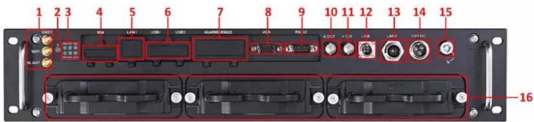
text_image
1 2 3 4 5 6 7 8 9 10 11 12 13 14 15 GASSE SIM LAN1 USB1 USB2 ALAMR/RS422 VCA RS.32 A OUT K C N L I E L A2 T H N Y D G WIFI M-ANT 16Figure 1.1 Panel View
Table 1.1 Interface's Descripon
| No. | Name | Descripon |
| 1 | GNSS | GNSS antenna interface |
| WIFI | Wi-Fi antenna interface. (only supported by the "/GW" devices) | |
| M-ANT | 3G antenna interface | |
| 2 | IR | IR: IR receiverReceive IR signal from remote control. |
| 3 | Indicators | PWR: Power indicatorTurns green aer device starts up; Turns red when device stands by. |
| RDY: Ready indicatorTurns green when the device starts up | ||
| REC: Record indicatorTurns green when recording; The light is out when all recording processes are abnormal. | ||
| GNSS: GNSS indicatorNo light when GNSS module is abnormal; Turns green when the GNSS module works normally; Blinks in green aer the posioning successful. | ||
| ANT: 3G indicatorTurns green when 3G module works normally; Blinks slowly in 3G registraon;Blinks frequently aer successful 3G registraon. | ||
| ALM: Alarm indicatorTurns red when alarm occurs. | ||
| 4 | SIM | SIM card slot. |
| 5 | LAN1 | RJ45 network interface for debugging. |
| 6 | USB1 | USB 3.0 interface. |
| USB2 | ||
| 7 | ALARM&RS422 | ● 2-ch relay signal output.● 8-ch relay signal input.● 1 RS-422 interface |
| 8 | VGA | VGA output. |
| 9 | RS232 | Serial interface. |
| 10 | A OUT | Audio output. |
| 11 | V OUT | Video output. |
| 12 | LINE | Interface for mobile intercom. |
| 13 | LAN2 | M12 network interface for connecng IP cameras and network transmission. |
| 14 | 110 VDC | Power supply. |
| 15 | Lock | Hard drive lock. |
| 16 | Hard Drive Enclosure | 3 hard drive caddies for 2.5 inch SATA HDDs/SSDs |
1.2 SIM Card Installaon
Purpose:
Pluggable 3G module is designed for the Rail NVR and you should install the SIM card to realize the 3G funcon.
Perform the following steps to install the SIM card on the Rail NVR
Before you start:
Put on the anstac gloves before the installaon.
Steps:
- Open the cover of SIM card slot.
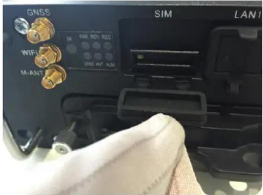
text_image
GNSS WIFI M-ANT IR 200 MHz REC GNS ANT ALM SIM LAN1Figure 1.2 Open Cover
- To pop up SIM card base, use a screw driver to press the yellow buon marked by the red frame in the following gure.
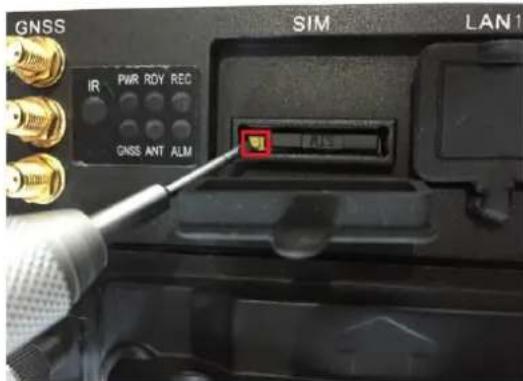
text_image
GNSS IR PWR RDY REC GNSS ANT ALM SIM LAN1Figure 1. 3 Press Yellow Buon
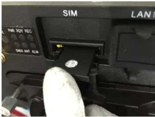
- Pull out SIM card base.
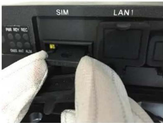
text_image
SIM LAN1 PMR RDY REC ONDS ANT ALMFigure 1.4 Pull Out SIM Card Base
- Place the SIM card into the SIM card base with the golden area facing up.

natural_image
Close-up of a gloved hand holding a small electronic component with gold contacts (no visible text or symbols)Figure 1.5 SIM Card Base
- Push the SIM card base back into the SIM card slot boom.
text_image
SIM LAN1 PWR RDY REC ONDS ANT ALMFigure 1. 6 Push SIM Card Base into Slot
1.3 HDD Installaon
Purpose:
3 HDD boxes are provided. You can install 2 HDDs for each HDD box. That is up to 6 HDDs can be installed. Perform the following steps to install the HDD on the Rail NVR.

- Use the factory recommended 2.5-inch HDD. You can ask technical support for information of factory recommended.
For single HDD installaon, the thickness of the HDD should be 9.5mm or 7mm; for double HDD installaon, the thickness of each HDD should be 7mm. - Initialize the HDD for recording aer the installaon. Otherwise, the system will give an audible warning for HDD error. For details, see 4.1.1 Inializing the HDD.
Tools needed:
● Two 2.5-inch SATA HDD
- Anstac gloves
● Key of hard disk lock
- Screwdriver
- Screws
Steps:
-
Put on the an-stac gloves.
-
Insert the key and rotate it from


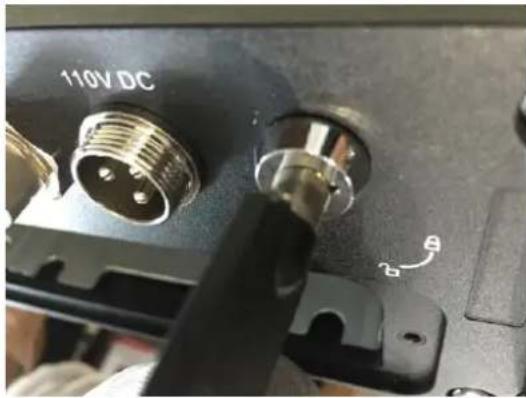
natural_image
Close-up of a mechanical component with two connectors and a 110V DC label, showing no readable text or symbols beyond the label.Figure 1. 7 Unlock HDD Box
- Pull out the HDD box.
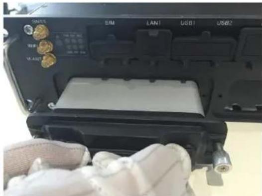
natural_image
Interior view of a device showing labeled ports (SIM, LAN1, USB1, USB2) and a gloved hand holding a white object (no readable text or symbols)Figure 1.8 Pull HDD Box
- Use a screwdriver to loosen and remove the two set screws marked in the gure.

natural_image
Close-up of hands in white gloves and blue plastic tool holding a small object, no visible text or symbolsFigure 1.9 Loosen and Remove Screws
- Separate the HDD box in to parts.
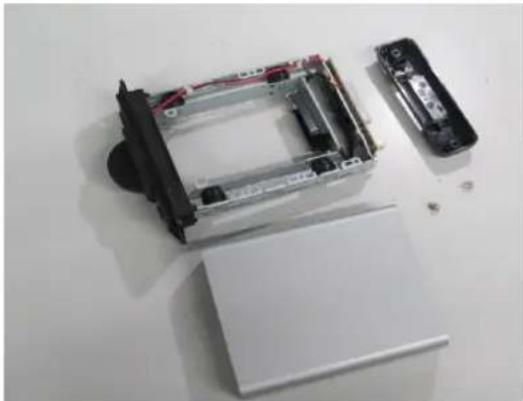
natural_image
Disassembled electronic device with exposed internal components and a partially open base (no text or symbols visible)Figure 1. 10 HDD Box Parts
- Place the rst HDD into the HDD box and ghtly insert the rst HDD into the boom, with the PCB facing downward.

natural_image
Close-up of hands installing a hard disk into a device casing (no visible text or symbols)Figure 1. 11 Install the First HDD
- Place the second HDD into the HDD box, with the PCB facing upward. Aer the HDD is totally placed into the bracket, ghtly insert the second HDD into the socket.

natural_image
Close-up of hands holding a computer hard drive with visible internal components (no text or symbols)Figure 1. 12 Install the Second HDD
- Tighten the two screws marked in the gure to x the HDD. Do the same things to x the other HDD at the back side.
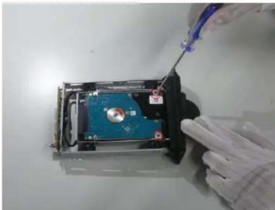
natural_image
Close-up of a gloved hand holding a screwdriver next to a compressed hard disk drive (no visible text or symbols)Figure 1. 13 Fix HDDs
- Tighten the 4 set screws on the side of the HDD box, shown as the following gure.

natural_image
Person in white gloves handling a mechanical device with a blue tool (no visible text or symbols)Figure 1. 14 Fix HDDs
- Align the protecve cover of the HDD box with the line marked in the gure, and assemble the whole HDD box.
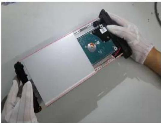
natural_image
Person in gloves handling a device with a green circuit board and black components (no visible text or symbols)Figure 1. 15 Assemble HDD Box
- Tighten the two set screws of the hard disk box, as shown in the gure.

natural_image
Person in gloves assembling a mechanical component with red and blue parts (no visible text or symbols)Figure 1. 16 Tighten Screws
- Insert the HDD box back to the Rail NVR, and then ghten the screws clockwise.

natural_image
Person in gloves holding a tablet device on a white surface (no visible text or symbols)Figure 1. 17 Insert HDD Disk Back to Rail NVR
1.4 Wiring
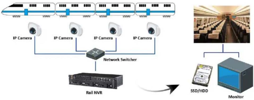
Purpose:
Wire and install your Rail NVR according to the following requirements.
● Power supply
Rail NVR should connect with power supply which should be 110 VDC.
● Network conncon
LAN 2 is connected to a network switcher.
IP Camera
Make sure network communicaon between IP cameras to be added and your Rail NVR is well.
● Video and audio output
If you want to operate Rail NVR via CVBS displayer, connect the A OUT and V OUT to a CVBS displayer.
If you want to operate Rail NVR via VGA displayer, before you start Rail NVR, connect the Rail NVR to a VGA displayer via a VGA cable.
HDD
Install at least one HDD into the Rail NVR. For detailed steps, refer to 1.3 HDD installaon.
- Mouse
Connect a mouse to one of the USB interface.
flowchart
graph TD
    A["High-speed Rail"] --> B["IP Camera"]
    C["High-speed Rail"] --> D["IP Camera"]
    E["High-speed Rail"] --> F["IP Camera"]
    G["High-speed Rail"] --> H["IP Camera"]
    B --> I["Network Switcher"]
    D --> I
    F --> I
    H --> I
    I --> J["Rail NVR"]
    J --> K["Monitor"]
    L["SSD/HDD"] --> K
Figure 1.18 Wiring
Chapter 2 Geng Started and Basic Operaons
Purpose:
Perform following seconds to start and congure your Rail NVR. It makes you can perform basic operaons, including local menu operaon, adding IP cameras, recording, etc.
2.1 Start-up
Before you start:
Wire your device according to 1.4 Wiring.
Step:
-
Insert the key into the Lock slot in front panel.
-
To start up device, rotate it from ☐ to ☐ You will see the startup picture indicang device is starng.

text_image
NVR Embedded Mobile loadingFigure 2.1 Startup Picture
2.2 Right-Click Menu and Main Menu
2.2.1 Right-Click Menu
Purpose:
Right-click menu is a shortcut for several operaons.
Step:
Right click on Live View. Then the right-click menu pops up.
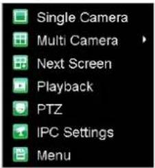
text_image
Single Camera Multi Camera Next Screen Playback PTZ IPC Settings MenuFigure 2.2 Right Click Menu
Table 2.1 Right Click Menu Descripon
| Item | Descripon |
| Single Camera | Switch to the single full screen by choosing camera number from the drop-down list. |
| Mul Camera | Adjust the screen layout by choosing from the drop-down list. 2*2, 3*3, and 4*4 are provided. |
| Next Screen | Click to switch to the next screen. |
| Playback | Enter the playback interface and start playing back the video of th selected channel immediately. |
| PTZ | Enter the PTZ control interface. |
| IPC Sengs | You can add, edit, and delete IP cameras. |
| Menu | Enter the main menu of the system by right clicking the mouse. |
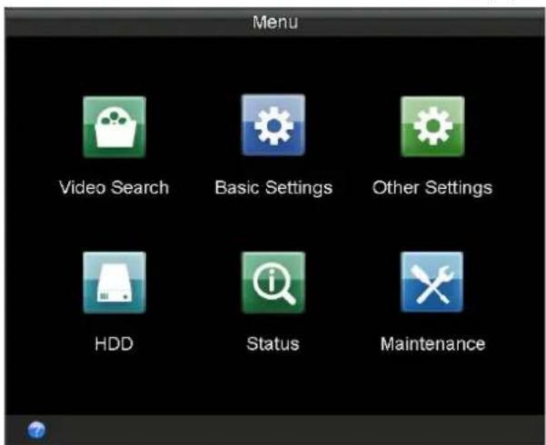
2.2.2 Main Menu
Purpose:
To congure Rail NVR parameters, you need to enter main menu rst.
Step:
Right click on Live View interface and click to select Menu item. Then Main Menu pops up.
text_image
Menu Video Search Basic Settings Other Settings HDD Status MaintenanceFigure 2.3 Main Menu
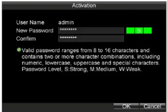
2.3 Seng Admin Password
Purpose:
For the rst-me access, you need to acvate the device by seng an admin password. No operaon is allowed before acvaon.
Steps:
- Create the password by inpung the same password in the text eld of New Password and Conrm.
text_image
Activation User Name admin New Password ******** S Confirm ******** ✓ Valid password ranges from 8 to 16 characters and contains two or more character combinations, including numeric, lowercase, uppercase and special characters. Password Level, S:Strong, M:Medium, W:Weak. OK CancelFigure 2.4 Sengs Admin Password

STRONG PASSWORD RECOMMENDED- We highly recommend you create a strong password of your own choosing (using a minimum of 8 characters, including upper case leers, lower case leers, numbers, and special characters) in order to increase the security of your product. And we recommend you reset your password regularly, especially in the high security system, reseng the password monthly or weekly can beer protect your product.
- Click OK to save the password and acvate the device.
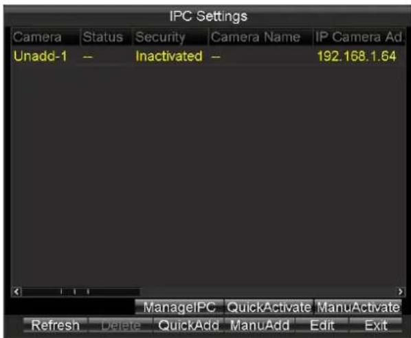
2.4 IP Camera Management
Purpose:
You need to acvate IP cameras rst and then add them.
Before you start:
Ensure the network communicaon between IP camera and Rail NVR is well.
Steps:
● To enter IP Camera Sengs interface through main menu, do following steps:
Enter the Local Network Sengs interface.
Main Menu > Other Sengs > IPC Sengs
● To enter IP Camera Sengs interface through right-click menu, do following step:
Right click on Live View interface and click to select IPC Sengs in right-click menu.
text_image
IPC Settings Camera Status Security Camera Name IP Camera Ad Unadd-1 -- Inactivated -- 192.168.1.64 ManagelPC QuickActivate ManuActivate Refresh Delete QuickAdd ManuAdd Edit ExitFigure 2.5 IP Camera Sengs
2.4.1 Acvang IP Camera
Purpose:
Before adding the cameras, make sure the IP cameras to be added are in acve status. Or you need to follow the steps to acvate it. Two methods are provided to acvate IP camera, including quick acvaon and manual acvaon.
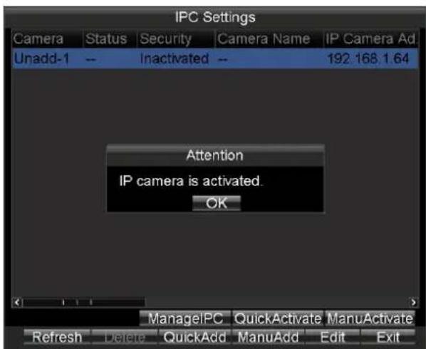
Quick Acvaon
Purpose:
You can duplicate the Rail NVR's password to IP camera by quick acvaon.
Steps:
- Enter IPC Sengs interface.
- Click to select IPC you want to acvate.
- Click the button to save aon.
text_image
IPC Settings Camera Status Security Camera Name IP Camera Ad Unadd-1 -- Inactivated -- 192.168.1.64 Attention IP camera is activated. OK ManagelPC QuickActivate ManuActivate Refresh Delete QuickAdd ManuAdd Edit ExitFigure 2.6 Quick Acvaon
Manual Acvaon
Purpose:
You can acvate the IP camera by seng your custom password.
Steps:
- Enter IPC Sengs interface.
- Click to select IPC you want to acvate.
- Click the button to enter manual Acvaon interface.
- Create a password by inpung the same password in both New Password and Conrm.
- Click OK to save the password and acvate the password.
text_image
IPC Settings Camera Status Security Camera Name IP Camera Ad Una IP Camera Manual Activation 64 New Password ********** Confirm ********** ✓ Valid password ranges from 8 to 16 characters and contains two or more character combinations, including numeric, lowercase, uppercase and other characters. OK Cancel > ManageIPC QuickActivate ManuActivate Refresh Delete QuickAdd ManuAdd Edit ExitFigure 2.7 Manual Acvaon
2.4.2 Adding IP Camera
Purpose:
The online IP cameras in the same network segment with the system would be displayed on a list.
Quick Adding
Purpose:
Quick adding is designed for the IPC with the same password with your Rail NVR.
Steps:
- Enter IPC Sengs interface.
- Click to select the IPC you want to add.
- Click the button add
Manual Adding
Purpose:
You can manually add the IP cameras that are not in the same network segment with your Rail NVR.
Steps:
- Enter IPC Sengs interface.
-
Click the ManuAdd buon to enter Add IP Camera Manually interface.
-
Select the IP channel No. for the IP camera.
- Input the required informaon, including the IP Address, Protocol, Port No., User Name, and Password.
- Click the Protocol buon, and you can customize the protocol according to the actual needs.
- Click OK to add the IPC.

● Up to 16 IP cameras can be added to the system.
● The icon indicates the IP camera is oine.
- The icon indicates the connected IP camera works properly.
text_image
IPC Settings Camera Status Security Camera Name IP Camera Ad Una Add IP Camera Manually Channel No. D1 IP Address Factory HIKVISION Port 8000 Sub Channel 1 User Name admin Password Protocol OK Cancel ManageIPC QuickActivate ManuActivate Refresh Delete QuickAdd ManuAdd Edit ExitFigure 2.8 Manual Add
2.4.3 Managing IP Camera
Purpose:
You can modify IP address and password of IP cameras, including added IP cameras and unadded IP cameras.

You need to re-add the added IP cameras aer you modify its password.
Steps:
- Click to select an IP camera.
- Click the book to enter Manage IPC Devices interface.

text_image
Manage IPC Devices Channel No. D1 IP Address 10 .16 .1 .250 Port 8000 User Name admin Password(Old) ******** Password(New) Confirm OK CancelFigure 2.9 Manage IPC Devices
- To modify IP address, do following steps:
1) Edit the IP Address.
2) Input Password (Old).
3) Click OK to save the new password.
- To modify password, do following steps:
1) Input Password (Old).
2) Input the same password in Password (New) and Conrm.
3) Click OK to save the sengs
2.4.4 Eding IP Camera
Purpose:
You can edit the added IP camera's informaon. You needn't re-add the IP camera aer eding it.
Steps:
- Click to select an added IP camera.
- Click the button to enter Edit Added IP Camera.
- Edit IP Address, Factory, Port, Sub Channel, User Name, or Password.
- Click OK to save the sengs.

text_image
Edit Added IP Camera Channel No. D1 IP Address 10 . 16 . 1 . 250 Factory HIKVISION Port 8000 Sub Channel 1 User Name admin Password ******** OK CancelFigure 2. 10 Edit IP Camera
Chapter 3 Network Sengs
Purpose:
You can congregate local network, dialing, Wi-Fi parameters.
text_image
Basic Settings Record Network Serial Port Start Dial WiFi Position G-Sensor PlatformFigure 3.1 Basic Sengs
Table 3.1 Sub-Menu Descripon
| Sub-Menu Name | Descripon |
| Network | You can congregate network parameters. |
| Dial | You can connect the device to the network and transmit the data aer dialing to internet. |
| WiFi | You can connect the device to the Wi-Fi networks and transmit the data via the Wi-Fi. |
3.1 Local Network Sengs
Purpose:
You can congregate the basic network parameters and me synchronizaon parameters.
3.1.1 Network Sengs
Purpose:
You need congure the basic network parameters to ensure well network communicaon.
Before you start:
Connect the LAN 2 to a network switch with network cable.

Port 1 and Port 2 respectively represent LAN 1 and LAN 2. LAN 1 is for debugging. LAN 2 is for connecng IP cameras and network transmission.
Steps:
- Enter the Local Network Sengs interface.
Main Menu > Basic Sengs > Network
-
Select Ethernet Port as Port 2.
-
Input the device IP address, Subnet Mask, Default Gateway, Preferred DNS Server, Alternate DNS Server in the corresponding text elds.
- Download Server IP: To upload videos to the Auto Backup Server, you need to input the IP address of server, where the tool locates, in Download Server IP text eld. You can ask technical support for the Auto Backup Server.
IP address: LAN 2's default IP address is 192.1.0.64.
- Click OK to save the sengs.

text_image
Network Settings Ethernet Port Port 1 IP Address 10 .16 .1 .110 Subnet Mask 255 .255 .255 .0 Default Gateway 10 .16 .1 .254 Preferred DNS Server 10 .1 .7 .88 Alternate DNS Server . . . Download Server IP . . . MAC Address 00:40:30:d8:5a:d1 Static IP Address 192.0.0.65 NTP Set Apply OK CancelFigure 3.2 Local Network Sengs
3.1.2 Time Synchronizaon
Purpose:
You can synchronize Rail NVR's me with NTP server.
Steps:
- Enter the Local Network Sengs interface.
Main Menu > Basic Sengs > Network - Click the Set buon of NTP.
- Check the checkbox of NTP to enable the NTP sengs.
- Input the Synchronizaon Interval.
- Input the IP address of NTP Server.
- Click OK to save the new sengs and exit.
- Click Apply to save the new sengs and click OK to exit.
text_image
NTP NTP Synchronization Interval 60 min(s) NTP Server OK CancelFigure 3.3 NTP Sengs
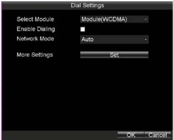
3.2 Dialing
Purpose:
You can connect the device to the network and transmit the data aer dialing to internet.
Before you start:
Install a 3G SIM card on the Rail NVR. For details, refer to 1.2 SIM Card Installaon.
Steps:
- Enter the 3G Dialing Sengs interface.
Main Menu > Basic Sengs > Dial
text_image
Dial Settings Select Module Module(WCDMA) Enable Dialing Network Mode Auto More Settings Set OK CancelFigure 3. 4 3G Dialing Sengs
-
Check the checkbox of Enable Dialing to enable the 3G dialing function of the device.
-
Select Network Mode as Auto, Adjust, or 3G Only.
● Auto: the work mode is set as the detected stronger signal.
- Adjust: the work mode is set as the 3G mode, as long as 3G signal is detected, even if it is weak.
● 3G Only: the network mode is set as 3G mode, that is 2G mode is not available.
- Oponally, if you have a dedicated dialing network, you can congregate the 3G VPDN (Virtual Private Dialup Network) sengs.
1) Click the Set buon of More Sengs.
2) Input the APN (access point name), Dialing Number, User Name, and Password.
3) Select the Vericaon Protocol.
4) Click OK to save the sengs and exit the interface.

text_image
Dial Settings APN Dial Number User Name Password Verification Protocol AUTO OK CancelFigure 3.5 APN
- Click OK and reboot the device to acvate the new sengs.
- You can view the dialing status on the Dialing Status interface (Main Menu > Status > Dial).
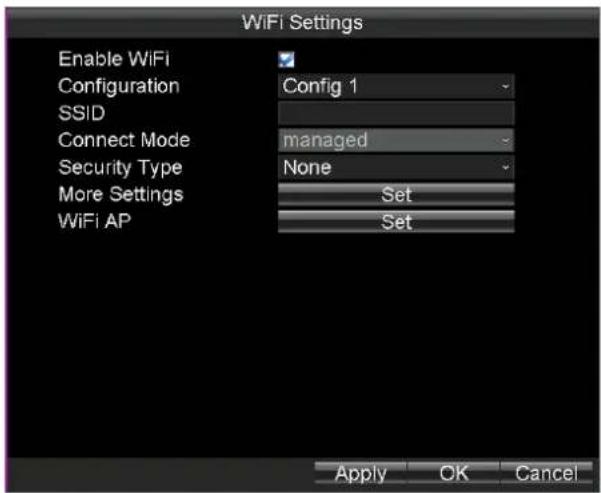
3.3 Wi-Fi
Purpose:
You can connect the device to the Wi-Fi networks and transmit the data via the Wi-Fi.
Step:
Enter the Wi-Fi Sengs interface.
Main Menu > Basic Sengs > WiFi
text_image
WiFi Settings Enable WiFi Configuration SSID Connect Mode Security Type More Settings WiFi AP Config 1 managed None Set Set Apply OK CancelFigure 3.6 Wi-Fi Sengs
3.3.1 Wi-Fi Sengs
Steps:
- Check the checkbox of Enable WiFi to turn on the Wi-Fi sengs.
- Select the Conguraon le to which you want to connect.

Rail NVR can remember 5 Wi-Fi in the 5 conguraon les. To connect Wi-Fi conveniently, congure Wi-Fi parameters to which you connect frequently in these conguraon les.
- Input the network SSID (Service Set Idener).
- Congure the Security Type.
1) Select Security Type as None, WEP, WPA2-PSK, or WPA-PSK.
2) If Security Type is set as WEP, you need to conjure Authencaon, Key length, and so on.
If Security Type is set as WPA2-PSK or WPA-PSK, you need to congregate Encrypon Type and Key.
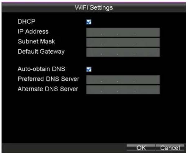
- To congregate automacally obtain Wi-Fi IP address and DNS server address, do following steps:
1) Click the Set buon of More Sengs.
2) Check the checkbox of DHCP and Auto-obtain DNS to obtain IP address and DNS server for Wi-Fi network automatically. By default they are checked.
3) Click OK to save the sengs and go back to upper menu.
- Click OK to save the new sengs and exit.
text_image
WiFi Settings DHCP IP Address Subnet Mask Default Gateway Auto-obtain DNS Preferred DNS Server Alternate DNS ServerFigure 3. 7 IP & DNS Sengs for Wi-Fi
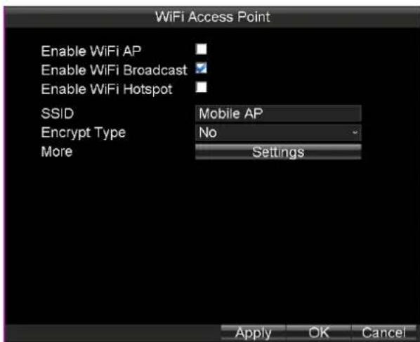
3.3.2 Wi-Fi AP Sengs
Purpose:
To congure WiFi AP, WiFi Broadcast, and Wi Hotspot, do following steps.
Steps:
- To Click the Set buon of WiFi AP.
- Oponally, check the checkbox of Enable WiFi AP, Enable WiFi Broadcast, and Enable WiFi Hotspot.
To access internet via Rail NVR, check the checkboxes of Enable WiFi AP and Enable WiFi Hotspot. - Edit SSID and select Encrypt Type.
- Click Sengs of More to congure parameters of WiFi access point.
- Click OK to save the sengs and go back to upper menu.
- Click OK to save the sengs and exit.

text_image
WiFi Access Point Enable WiFi AP Enable WiFi Broadcast Enable WiFi Hotspot SSID Mobile AP Encrypt Type No More Settings Apply OK CancelFigure 3.8 Wi-Fi Access Point Sengs
Chapter 4 Record Sengs
4.1 Conguring Encoding Parameters
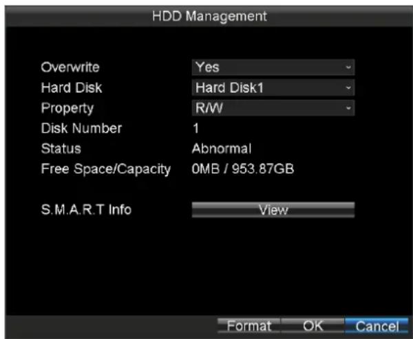
4.1.1 Inializing the HDD
Before you start:
Install at least one HDD on the Rail NVR for video data storage.
Steps:
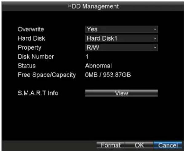
- Enter the HDD Management interface.
Main Menu > HDD
text_image
HDD Management Overwrite Yes Hard Disk Hard Disk1 Property R/W Disk Number 1 Status Abnormal Free Space/Capacity 0MB / 953.87GB S.M.A.R.T Info View Format OK CancelFigure 4.1 HDD Management
- Select the Hard Disk you want to format from the drop-down list.
- Click the Format buon and click OK in popup conrmaon window to start formang.
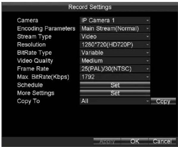
4.1.2 Conguring Record Sengs
Purpose:
You can congregate the transmission stream type, the resolution, frame rate, etc.
Steps:
- Enter the Record Sengs interface.
Main Menu > Basic Sengs > Record
text_image
Record Settings Camera IP Camera 1 Encoding Parameters Main Stream(Normal) Stream Type Video Resolution 1280*720(HD720P) BitRate Type Variable Video Quality Medium Frame Rate 25(PAL)/30(NTSC) Max. BitRate(Kbps) 1792 Schedule Set More Settings Set Copy To All Copy Apply OK CancelFigure 4.2 Record Sengs
- Select the camera from the drop-down list.
- Congure the following sengs:
- Encoding Parameters
Main Stream (Normal): used for schedule recording;
Main Stream (Event): used for event recording;
Sub Stream: used for network transmission.
- Stream Type
Video and Video & Audio are selectable.
- Resoluon
Select the resolution for the selected camera and stream type. WD1, 4CIF, 2CIF and CIF are selectable.
- Bitrate Type
Variable and Constant are selectable.
The video quality is congorable when you select Variable to the bitrate type; and the video quality is set as Medium by default and cannot be edited when you select Constant to the bitrate type.
- Video Quality
If you select Variable to the bitrate type, you can set the video quality as Highest, Higher, Medium, Low, Lower and Lowest.
Frame Rate
Frame rate refers to the frequency of the image frame aer compression. With other parameters constant, reduce the video frame rate, and you can lower the maximum bitrate to some extent.
● Max. Bitrate(Kbps)
Select the xed value provided by the system or customize the maximum bitrate as desired.
- Click the Set buon of Schedule to enter the record schedule interface.
1) Check the check box of Enable Schedule to enable the record schedule sengs.
2) Select the day from the drop-down list for sengs.
3) Check the checkbox of All Day to enable all-day recording, and then select the recording type from the drop-down list.
You can also uncheck the checkbox of All Day, customize the me period for recording, and select the recording type for each me period.
4) Click OK to save the new sengs and exit.
You can view the recording status on the Record Status interface (Main Menu>Status>Record).

- 5 recording types are selectable: Normal, Moon Detecon, Alarm, Moon | Alarm and Moon & Alarm.
● Up to 8 me periods can be set for each day and each of the me periods cannot be overlapped.
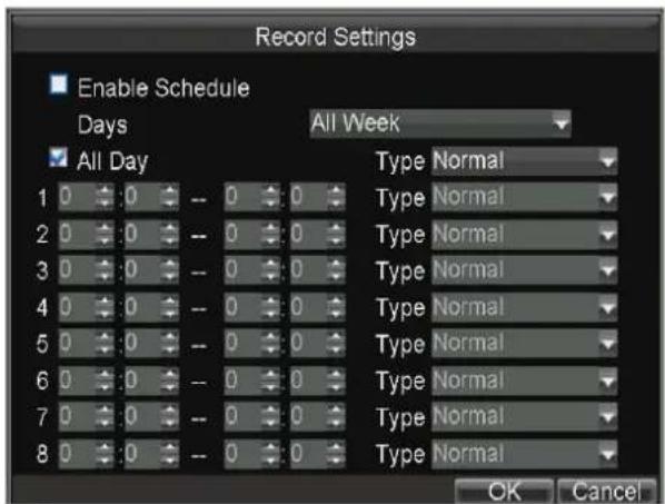
Figure 4.3 Record Schedule Sengs
- Click the Set buon of More Sengs to conjure the pre-record and post-record me.
● Pre-record: Normally used for the event (moon or alarm) triggered record, when you want to record before the event happens. For example, when an alarm occurs at 10:00, if the pre-record me is set as 5 seconds, the camera records the alarm at 9:59:55.
- Post-record: Aer the event nished, the video can also be recorded for a certain me. For example, when an alarm ends at 11:00, if the post-record me is set as 5 seconds, the camera records II 11:00:05.
- Oponally, you can select the camera and click Copy to copy the current sengs to the selected camera.
- Click Apply to save the sengs and click OK to exit.
4.2 Conguring Moon Detecon Record
Purpose:
In the moon detecon record, once a moon event occurs, the device starts to record and mulple linkage acons will be triggered.
Steps:
- For detailed steps, you can refer to 7.2.5 Conguring Moon Detecon.
- Enter the Record Sengs interface, and select Moon as the record type to set the arming schedule of moon detecon record.
Main Menu > Basic Sengs > Record Sengs > Schedule
4.3 Conguring Alarm Triggered Record
Purpose:
Follow the procedure to conjure alarm triggered recording.
Steps:
- For detailed steps, refer to 7.5.2 Alarm Input Sengs.
- Enter the Record Sengs interface to and select Alarm as the record type. Main Menu > Basic Sengs > Record Sengs > Schedule
Chapter 5 Video Search and Export
Purpose:
You can search and play back the videos stored on the device.
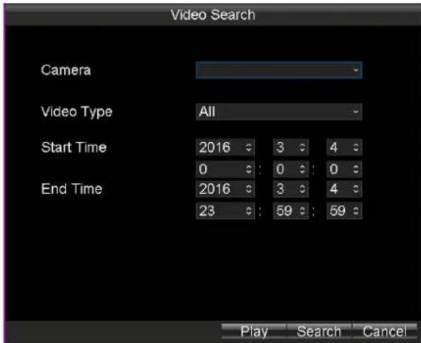
Step:
Enter the Video Search interface.
Main Menu > Video Search
text_image
Video Search Camera Video Type All Start Time 2016 3 4 0 : 0 : 0 End Time 2016 3 4 23 : 59 : 59 Play Search CancelFigure 5.1 Video Search Interface
5.1 Searching Videos
Purpose:
You can search and play back the videos stored on the device.
Steps:
- Enter the Video Search interface.
Main Menu > Video Search
- Specify the Camera and Video Type from the drop-down list.
- Specify the Start Time and End Time for search.
- Click Search to search. If there are videos match the search conditions, they would be listed in the Search Results interface. Or the prompt "No record le found." appears.

text_image
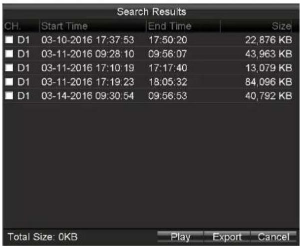
Search Results CH. Start Time End Time Size ■ D1 03-10-2016 17:37:53 17:50:20 22,876 KB ■ D1 03-11-2016 09:28:10 09:56:07 43,963 KB ■ D1 03-11-2016 17:10:19 17:17:40 13,079 KB ■ D1 03-11-2016 17:19:23 18:05:32 84,096 KB ■ D1 03-14-2016 09:30:54 09:56:53 40,792 KB Total Size: 0KB Play Export CancelFigure 5.2 Search Results.
5.2 Playing Video
Purpose:
You can play back the history videos.
5.2.1 Playing by Time
Purpose:
You can specify a period, and then start playing back all the video segments in the period connually.
Steps:
- Enter the Video Search interface.
Main Menu > Video Search
-
Specify the search conditions, including Camera, Video Type, Start Time, and End Time.
-
Click Play to start playback. If there are videos match the search conditions, the playback window appears.
Or the prompt "No record le found." appears.
5.2.2 Playing by File
Purpose:
You can specify a video le to playback.
Steps:
- Search out the videos to play back. For details, refer to 5.1 Searching Video.
text_image
Search Results CH. Start Time End Time Size ■ D1 03-10-2016 17:37:53 17:50:20 22,876 KB ■ D1 03-11-2016 09:28:10 09:56:07 43,963 KB ■ D1 03-11-2016 17:10:19 17:17:40 13,079 KB ■ D1 03-11-2016 17:19:23 18:05:32 84,096 KB ■ D1 03-14-2016 09:30:54 09:56:53 40,792 KB Total Size: 0KB Play Export CancelFigure 5.3 Search Results
- Search Results
- Click to select the videos to playback.
- Click Play to start playing it.

natural_image
Exterior view of a blue freight train on railway tracks inside a tunnel, illuminated by artificial lighting (no signage or text visible)Figure 5.4 Playback Window
5.2.3 Managing Playback Control Bar
Purpose:
You can mute playback and clip videos during playback process.
Steps:
● To exit playback, do following steps:
1. Right click the playback window.
2. Click Exit to exit playback process.

Figure 5.5 Playback Right-Click Menu
● To hide playback control bar, do following steps:
-
Right click the playback window.
-
Click Control Panel to hide control bar.
- Repeat step 1) to 2) to show control bar.

text_image
55%Figure 5.6 Control Bar
● To mute playback process, do following steps:
- Click the icon in control bar to mute.
- Click the icon again to turn on audio.
● To clip videos, do following steps:
-
Connect a USB ash drive to the USB interface of Rail NVR.
-
Click the icon in control bar to start clip.
-
Click the icon again to stop clip.
-
Repeat step 2) to 3) to clip more.
-
When exit the playback, the prompt reminds you to export clips appears, click OK in the prompt to export the video clips to USB ash drive.

Figure 5.7 Export Clips
5.3 Exporng Video
Purpose:
To back up video, you can export videos to USB ash drive.
Steps:
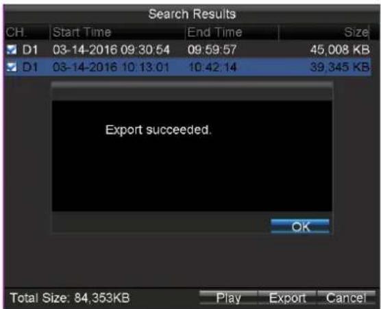
- Connect a USB ash drive to the USB interface of Rail NVR.
- Search out videos you want to export. For details, refer to 5.1 Searching Video.
- Check the checkboxes of videos you want to export.
- Click Export to start exporng. The exported videos would be saved in the connected USB ash drive.
text_image
Search Results CH. Start Time End Time Size D1 03-14-2016 09:30:54 09:59:57 45,008 KB D1 03-14-2016 10:13:01 10:42:14 39,345 KB Export succeeded. OK Total Size: 84,353KB Play Export CancelFigure 5.8 Export Succeeded
Chapter 6 Basic Sengs
Purpose:
There are nine sub-menus provided in Basic Sengs menu.

text_image
Basic Settings Record Network Serial Port Start Dial WiFi Position G-Sensor PlatformFigure 6.1 Basic Sengs
Table 6.1 Sub-Menu Descripon
| Sub-Menu Name | Descripon |
| Record | You can congregate the parameter for videos. |
| Serial Port | Two types of serial ports are provided: RS-232 and RS-485. |
| Start | You can specify the startup/shutdown me for the Rail NVR. |
| Posion | The built-in GNSS module supports GPS (Global Poisoning System), contribung to the device poisoning and speed limit alarm. |
| G-Sensor | G-Sensor detects and records the acceleraon speed informaon in 3-axial (X, Y, Z) direcons. |
| Plaorm | The Rail NVR can be remotely accessed via iVMS plaorm. Make sure the parameters congured are valid for the plaorm. |
6.1 Serial Port
Purpose:
Two types of serial ports are provided: RS-232 and RS-485.
Step:
Enter the Serial Port Sengs interface to congregate the parameters.
Main Menu > Basic Sengs > Serial Port
6.1.1 RS-232
Steps:
- Select Serial Port Type as RS-232.
- Select Parity.
-
Select Used As as Parameters Conguraon or Transparent Channel.
-
Parameters Conguraon: Connect a PC to the DVR through the PC serial port. DVR parameters can be congured by using soware such as HyperTerminal. The serial port parameters must be the same as of the device when connecng with the PC serial port.
-
Transparent Channel: Connect a serial device directly to the device. The serial device will be controlled remotely by the PC through the network and the protocol of the serial device.
-
Click OK to save the sengs.

text_image
Serial Settings Serial Port Type RS-232 Baudrate 115200 Data Bit 8 Stop Bit 1 Parity None Flow Control None Used As Console OK CancelFigure 6.2 RS-232
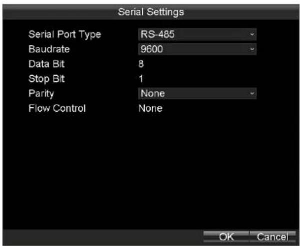
6.1.2 RS-485
Steps:
- Select Serial Port Type as RS-485.
- Congure Baudrate and Parity.

The RS-485 port can be used for transparent channel only.
- Click OK to save the sengs and exit.
text_image
Serial Settings Serial Port Type RS-485 Baudrate 9600 Data Bit 8 Stop Bit 1 Parity None Flow Control None OK CancelFigure 6.3 RS-485
6.2 Start Control
Purpose:
You can specify the startup/shutdown me for the Rail NVR.
Steps:
- Enter the Start Control interface.
Main Menu > Basic Sengs > Start
- Select Auto Work Type as Auto Working.
- Select the Date on which you want to start up/shut down the device automacally.
- Specify the Time Segment for the device to start up and shut down.
- Oponally, you can copy the sengs to other days in the week.
- Click OK to save the new sengs and exit.

Two periods can be congured for each day. And the me periods can't be overlapped each other.

text_image
Start Control Auto Work Type Date Time Segment 1 Time Segment 2 Date Copy Auto Working Monday 0 0 to 0 0 0 0 to 0 0 All OK CancelFigure 6.4 Start Control-Auto Working
6.3 Posion
Purpose:
The built-in GNSS module supports GPS (Global Poisoning System), contribung to the device poisoning and speed limit alarm.
Steps:
- Enter the Satellite Posioning Sengs interface.
Main Menu > Basic Sengs > Posion

text_image
Position Settings Position Module Built-in Satellite Time Adjusting Time Zone (GMT+08:00) Beijing, U Speed Unit km/h Speed Limit 100 Audio Alarm Trigger Alarm Output All 1 2 Display Channel Set OK CancelFigure 6.5 Satellite Posioning Sengs
- Select the mode of the Posion Module. Only Built-in is provided.
● Built-in: Obtain data from the satellite posioning module built in the Rail NVR. - Check the checkbox of Satellite Time Adjusting and then select the me zone in which the device locates.
- Select the Speed Unit and input the Speed Limit value.
- Set the linkage acons for speeding alarm, including Audio Alarm and Alarm Output. For details of alarm output sengs, see 7.5.3 Alarm Output Sengs.
- Click Set of Display Channel to congregate display channel. The device posioning informaon would be displayed on the selected channels.
- Click OK to save the new sengs and exit.
- You can view the device posioning status on the Posioning Status interface (Main Menu > Status > Posion).
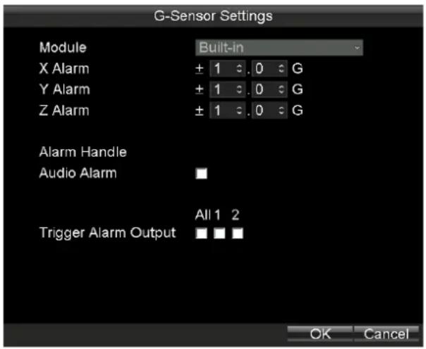
6.4 G-Sensor
Purpose:
G-Sensor detects and records the acceleraon speed informaon in 3-axial (X, Y, Z) direcons.
Before you start:
Connect an external sensor to the device for obtaining and providing the acceleraon speed in 3-axial direcons.
Steps:
- Enter the G-Sensor Sengs interface.
Main Menu > Basic Sengs > G-Sensor
text_image
G-Sensor Settings Module Built-in X Alarm ± 1 0 G Y Alarm ± 1 0 G Z Alarm ± 1 0 G Alarm Handle Audio Alarm Trigger Alarm Output All 1 2 OK CancelFigure 6. 6 G-Sensor Sengs
-
Select the mode of G-sensor Module. Only built-in module is provided.
Built-in: The G-sensor is built in the Rail NVR. -
Set the limit value for acceleraon alarm in X, Y and Z direcons.

X, Y and Z represent the direcon of acceleraon and the unit of alarm value is G (G=9.8 m/s ^2 ).
-
Set the linkage acons for acceleraon alarm, including Audio Alarm and Alarm Output. For details of alarm output sengs, see 7.5.3 Alarm Output Sengs.
-
Click OK to save the new sengs and exit.
-
You can view the G-sensor status on the G-sensor Status interface (Main Menu > Status > G-sensor).
6.5 Plaorm
Purpose:
The Rail NVR can be remotely accessed via iVMS plaorm. Make sure the parameters congured are valid for the plaorm.
Before you start:
● Create the device ID of Rail NVR on the iVMS plaorm.
- Ensure the network communicaon between Rail NVR and plaorm is well.
Steps:
- Enter the Plaorm Sengs interface.
Main Menu > Basic Sengs > Plaorm
text_image
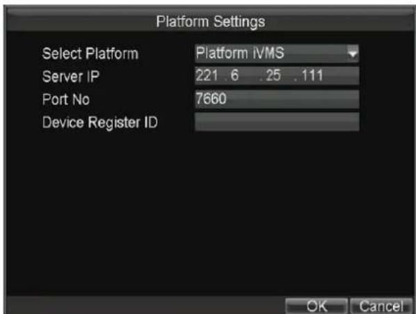
Platform Settings Select Platform Platform IVMS Server IP 221.6 .25 .111 Port No 7660 Device Register ID OK CancelFigure 6.7 iVMS Plaorm Sengs
-
Select Plaorm as Plaorm iVMS or 3G_SDK.
-
Plaorm WVS: Reserved
- Plaorm iVMS: It refers to iVMS-7200.
-
3G_SDK: It refers to plaorm developed by yourself based on the SDK provided by our company.
-
Congure the following parameters:
● Server IP: Input the stac IP address of iVMS server.
● Port No.: Input the port No. of iVMS server.
● Device Register ID: The ID of the Rail NVR registered on the iVMS plaorm.
- Register Password: Only needed when Plaorm is selected as 3G_SDK.
4. Click OK and reboot the device to acvate the new sengs.
5. You can view the plaorm status on the Plaorm Status interface (Main Menu > Status > Plat).
Chapter 7 Other Sengs
Purpose:
There are ten sub-menus provided in Basic Sengs menu.

text_image
Other Settings Display Camera User Preview Exception AlarmIn AlarmOut IPC Settings Firewall PTZFigure 7.1 Other Sengs
Table 7.1 Sub-Menu Descripon
| Sub-Menu Name | Descripon |
| Display | You can set the system me, select the CVBS output standard, enable the password, conjure the DST sengs, etc. |
| Camera | You can conjure the OSD (On Screen Display) sengs which includes the display of camera name, date and week, and the corresponding posion informaon. |
| User | You can add and manage users here. The admin user has all the operaon permissions of the device. |
| Preview | You can conjure the dwell me of live view window, set the camera order, enable/disable the audio preview, etc. |
| Excepon | You can conjure the handle acon for excepons. |
| Alarm In | You can conjure the sengs for alarm input, including trigger level, arming schedule, alarm linkage acons, etc. |
| Alarm Out | You can conjure the arming schedule, alarm duraon me, alarm name for alarm output. |
| Firewall | You can enable SSH service and add white list for Rail NVR. |
| PTZ | You can set the parameters for PTZ. |
7.1 Display Sengs
Purpose:
You can set the system me, select the CVBS output standard, enable the password, congure the DST sengs, etc.
Steps:
- Enter the Display Sengs interface.
Main Menu > Other Sengs > Display

The system language is set as English by default and is not editable.

text_image
Display Settings Language English CVBS Output Standard PAL System Time 2016 : 3 : 14 : 10 : 53 : 7 : VGA Resolution 1024*768/60HZ Enable Password DST Settings Set Advance Setting Set Apply OK CancelFigure 7.2 Display Sengs
- Oponally, you can do following steps to congregate the following parameters according to your needs.
- Set the CVBS Output Standard as NTSC or PAL according to the actual video input standard.
- Click and to Set the System Time.
- Select the VGA Resoluon from the drop-down list.

The VGA resoluon is only congorable when the Rail NVR is connected to a VGA monitor. And you can set it as 1024*768/60Hz, 1280*720/60Hz, 1280*1024/60Hz, 1600*1200/60Hz, or 1920*1080/60Hz.
- Check the checkbox of Enable Password to enable the password authencaon before operaons.
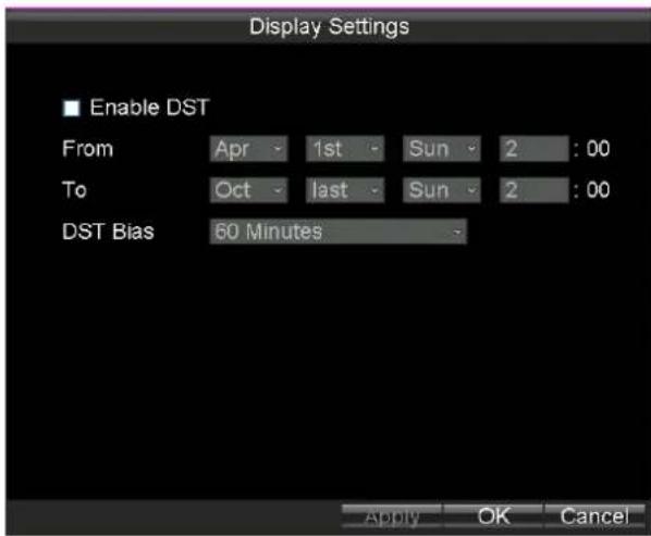
- Click the Set buon of DST Sengs, and you can conjure the DST (Daylight Saving Time) for the system. Perform the following steps to conjure the DST sengs.
1) Check the checkbox of Enable DST.
2) Set the start me and end me for the DST period.
3) Select the DST bias from the drop-down list.
4) Click Apply to save the sengs and click OK to exit.
text_image
Display Settings ■ Enable DST From Apr - 1st Sun 2 : 00 To Oct - last Sun 2 : 00 DST Bias 60 Minutes Apply OK CancelFigure 7.3 DST Sengs
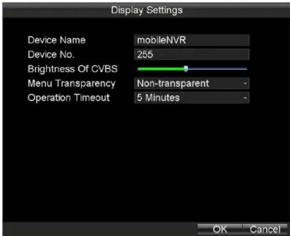
- Click the Set buon of Advance Sengs, and you can conjure the advanced parameters for display.
Device Name: Input the system name as desired in the text eld.
Device No.: Edit the device No. for remote control. The device No. ranges from 1 to 255. The default device No. is 255.

It is recommended not to modify the Device No.. Otherwise, you need to input the Device No. on the remote control every me you use it.
Brightness of CVBS: Adjust the video output brightness.
Menu Transparency: The transparency proporon of the menu displayed on the live view interface. You can set it as 1:3, 1:1, 3:1 or Non-transparent.

The smaller the proporcion value is, the more transparent the menu is.
When the Not Transparent is selected, only the menu is displayed on the interface.
➢ Operaon Timeout: If no operaons are done during the selected me, the live view interface will be displayed automatically.
text_image
Display Settings Device Name mobileNVR Device No. 255 Brightness Of CVBS Menu Transparency Non-transparent Operation Timeout 5 Minutes OK CancelFigure 7.4 Advanced Sengs
- Click Apply to save the sengs and click OK to exit.
7.2 Camera Sengs
Purpose:
You can congregate OSD, image, mask, video tamper-proof, moon detecon, and video loss parameters.
7.2.1 OSD Sengs
Purpose:
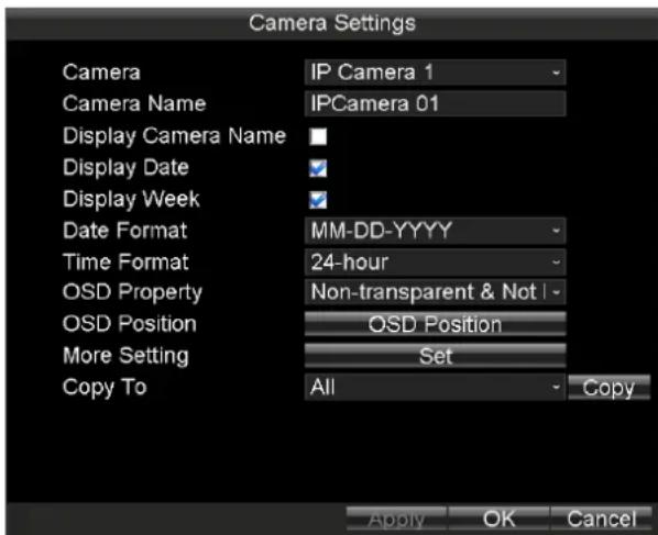
You can congregate the OSD (On Screen Display) sengs which include the display of camera name, date and week, and the corresponding posion informaon.
Steps:
- Enter the Camera Sengs interface.
Main Menu > Other Sengs > Camera
text_image
Camera Settings Camera IP Camera 1 Camera Name IPCamera 01 Display Camera Name Display Date Display Week Date Format MM-DD-YYYY Time Format 24-hour OSD Property Non-transparent & Not | OSD Position OSD Position More Setting Set Copy To All Copy Apply OK CancelFigure 7.5 Camera Sengs
- Select the Camera from the drop-down list.
- Input the Camera Name as desired in the text eld.
- Check the checkboxes of Display Camera Name, Display Date, or Display Week, thus to display camera name, date, and week in the live view interface for the selected camera.
- Select the Date Format and Time Format according to the actual needs, and then select the OSD property.
- To adjust OSD Posion, do following steps:
1) Click the OSD Posion buon
2) Drag the red bar which represents the Date/Time Posion and place it in the posion according to your needs.
3) Right click and click to select Camera Name Posion item.
4) Drag the red bar which represents the Camera Name Posion and place it in the posion according to your needs.
5) Right click and click to select Exit item.
- Click Apply to save the new sengs and click OK to exit.
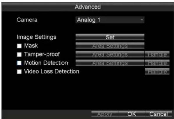
text_image
Advanced Camera Analog 1 Image Settings Set ■ Mask Area Settings ■ Tamper-proof Area Settings Handle ■ Motion Detection Area Settings Handle ■ Video Loss Detection Handle Apply OK CancelFigure 7.6 More Seng
7.2.2 Image Sengs
Purpose:
Perform the following steps to adjust the video parameters, including Brightness, Contrast, Saturaon and Hue.
Steps:
- Enter Camera Sengs interface.
Main Menu > Other Sengs > Camera Sengs - Click the Set buon of More Sengs.
- Click the Set buon of Image Sengs to enter the Image Sengs interface.
- Drag the slider to adjust value.
- You can click Default to restore the default video parameters.
- Click OK to save the new sengs.

text_image
Brightness Contrast Saturation Hue Default OK CancelFigure 7.7 Image Sengs Interface
7.2.3 Conguring Mask
Purpose:
The privacy mask can be set to prevent some certain spots in the surveillance area from being viewed or recorded. Perform the following steps to set a privacy mask:
Steps:
- Enter Camera Sengs interface.
Main Menu > Other Sengs > Camera Sengs
- Click the Set buon of More Sengs.
- Check the checkbox of Mask to enable the privacy mask funcon.
- Click the Area Sengs buon to set the mask area on the live view interface.
- Drag to draw a rectangle.
- Repeat step 3 to draw more rectangles.
- Right click and select Exit.

● Up to 4 mask areas can be congured for each channel.
● The mask area informaon of one channel cannot be copied to another one.
● You cannot view the image of the mask area either from the live view interface or videos.
7.2.4 Conguring Video Tampering Alarm
Purpose:
A tampering alarm is triggered when the camera is covered and the monitoring area cannot be viewed. Linkage acons including audible warning, alarm output, etc., can be set to handle it.
Steps:
- Enter the Advanced Camera Sengs interface.
Main Menu > Other Sengs > Camera Sengs
- Click the Set buon of More Sengs.
- Check the checkbox of Tamper-proof to enable the tamper-proof funcon.
- To set tamper-proof Area, do following steps:
1) Click the Area Sengs buon.

The video tampering alarm can be triggered only when the view of the camera is fully covered. The regional video tampering alarm funcon is reserved.
2) Draw a rectangle as the tamper-proof area.
3) To congure tamper-proof sensitivity, do following steps:
a) Right click and click to select Sensitivity.
b) Select Sensitivity as Low, Media, or High.
c) Click OK to exit
4) Right click and click to select Exit to exit area sengs interface.
- Click the Handle button of tamper-proof to set the arming schedule and alarm linkage acons.
1) Select the day from the drop-down list, and set the arming schedule for the alarm linkage acons.
2) Oponally, you can copy the current sengs to other days in the week.
3) Check the checkboxes to enable the corresponding linkage acons.
● Pop-up Image on Monitor
When an alarm is triggered, the local monitor displays the video image from the alarming channel congured for full screen monitoring.
- Audio Warning:
Trigger an audible beep when an alarm is detected.
● Trigger Alarm Output:
Trigger an alarm output when an alarm is detected.
4) Click Apply to save the new sengs and click OK to exit.

text_image
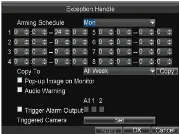
Exception Handle Arming Schedule Mon 1 0 :0 -24 0 5 0 :0 -0 :0 2 0 :0 -0 0 6 0 :0 -0 :0 3 0 :0 -0 0 7 0 :0 -0 :0 4 0 :0 -0 0 8 0 :0 -0 :0 Copy To All Week Copy ■ Pop-up Image on Monitor ■ Audio Warning All 1 2 ■ Trigger Alarm Output ADD OK CancelFigure 7.8 Linkage Acon of Tamper-proof
- Click Apply to save the new sengs and click OK to exit.
7.2.5 Conguring Moon Detecon
Purpose:
In the moon detecon record, once a moon event occurs, the device starts to record and multiple linkage acons will be triggered.
Steps:
- Enter the Advanced Camera Sengs interface.
Main Menu > Other Sengs > Camera Sengs
- Click the Set buon of More Sengs.

text_image
Advanced Camera IP Camera 1 Image Settings ■ Mask ■ Tamper-proof ✓ Motion Detection ■ Video Loss Set Area Settings Area Settings Handle Area Settings Handle Handle Apply OK CancelFigure 7.9 Moon Detecon Sengs
-
Check the checkbox of Moon Detecon to enable the moon detecon funcon.
-
To draw area for moon detecon, do following steps:
1) Click the Area Sengs buon.
2) Drag to draw red frame which is moon detecon area.
Oponally, you can right click and select Full-Screen Detecon to draw a full-screen area.
3) To set Sensitivity of moon detecon, do following steps:
a) Right click and select Sensitivity.
b) Select Sensitivity and click OK to save the sengs.
4) Right click and click to select Exit.
- Click the Handle buon of moon detecon to set the arming schedule and alarm linkage acons.
1) Select the day from the drop-down list, and set the arming schedule for the alarm linkage acons.
2) Oponally, you can copy the current sengs to other days in the week.
3) Check the checkboxes to enable the corresponding linkage acons.
● Pop-up Image on Monitor
When an alarm is triggered, the local monitor displays the video image from the alarming channel congured for full screen monitoring.
- Audio Warning:
Trigger an audible beep when an alarm is detected.
● Trigger Alarm Output:
Trigger an alarm output when an alarm is detected. For details of alarm output sengs, see 7.5.3 Alarm Output Sengs.
4) Click the Set buon of Triggered Camera to select the channel to be triggered.
5) Click Apply to save the new sengs and click OK to exit.
text_image
Exception Handle Arming Schedule Mon 1 0 :0 -- 24 :0 5 0 :0 -- 0 :0 2 0 :0 -- 0 :0 6 0 :0 -- 0 :0 3 0 :0 -- 0 :0 7 0 :0 -- 0 :0 4 0 :0 -- 0 :0 8 0 :0 -- 0 :0 Copy To All Week Copy ■ Pop-up Image on Monitor ■ Audio Warning All 1 2 ■ Trigger Alarm Output Triggered Camera Set Apply OK CancelFigure 7. 10 Linkage Acons of Moon Detecon
- Click Apply to save the new sengs and click OK to exit.
7.2.6 Conguring Video Loss
Purpose:
When the device cannot receive video signal from the front-end devices, the video loss alarm will be triggered. Linkage acons including audible warning, alarm output, etc., can be set to handle it.
Steps:
- Enter the Advanced Camera Sengs interface. Main Menu > Other Sengs > Camera Sengs
- Click the Set buon of More Sengs.
- Check the checkbox of Video Loss Detecon to enable the video loss detecon sengs.
- Click the Handle buon of Video Loss Detecon, and you can set the arming schedule and alarm linkage acons for video loss alarm. For detailed steps, see step 5 of 7.2.4 Conguring Video Tampering Alarm.
- Click Apply to save the new sengs and click OK to exit.
7.3 User Sengs
Purpose:
You can add and manage users here. The admin user has all the operaon permissions of the device.
7.3.1 Adding User
Steps:
- Enter the User Management interface.
Main Menu > Other Sengs > User
text_image
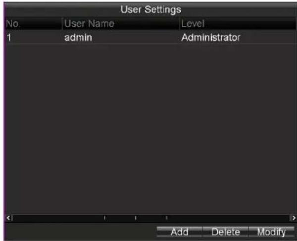
User Settings No User Name Level 1 admin Administrator Add Delete ModifyFigure 7.11 User Management
- Click the Add buon to enter the Add User interface.

text_image
Add User Name Test 01 Password ********** Confirm ********** ✓ Valid password ranges from 8 to 16 characters and contains two or more character combinations, including numeric, lowercase, uppercase and other characters. Level Guest Permission: preview, playback, log query OK CancelFigure 7. 12 Add User
- Input the informaon of the new user, including User Name, Password, and Conrm Password.

STRONG PASSWORD RECOMMENDED—We highly recommend you create a strong password of your own choosing (Using a minimum of 8 characters, including at least three of the following categories: upper case leers, lower case leers, numbers, and special characters.) in order to increase the security of your product. And we recommend you reset your password regularly, especially in the high security system, reseng the password monthly or weekly can beer protect your product.
-
Select the user Level from the drop-down list.
-
Operator: The operator has permissions of Preview, Playback, Backup, Log Search, and Parameters Sengs.
● Guest: The Guest has permission of Preview, Playback, Backup, and Log Search. -
Click the OK buon to save the sengs and go back to the User Management interface.
-
You can click the Delete buon to delete the selected user and click the Modify buon to modify the user informaon.
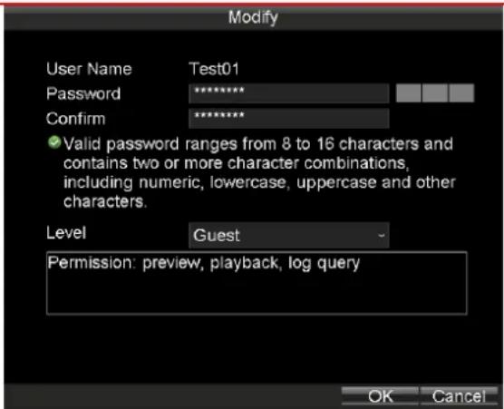
7.3.2 Modifying User
Steps:
- Click to select the user you want to modify.
- Click Modify.
- Edit the Password and Conrm. For admin user, you need to input Current Password for authority.
- Click OK to save the sengs.

STRONG PASSWORD RECOMMENDED—We highly recommend you create a strong password of your own choosing (Using a minimum of 8 characters, including at least three of the following categories: upper case leers, lower case leers, numbers, and special characters.) in order to increase the security of your product. And we recommend you reset your password regularly, especially in the high security system, reseng the password monthly or weekly can be protect your product.
text_image
Modify User Name Test01 Password ............. Confirm ............. ✓ Valid password ranges from 8 to 16 characters and contains two or more character combinations, including numeric, lowercase, uppercase and other characters. Level Guest Permission: preview, playback, log query OK CancelFigure 7. 13 Modify User
7.3.3 Deleng User
Steps:
- Click to select the user you want to modify.
- Click Delete.
- Click OK in popup conrmaon window to delete it.
7.4 Preview Sengs
Purpose:
You can congregate the dwell me of live view window, set the camera order, enable/disable the audio preview, etc.
Steps:
- Enter the Preview Sengs interface.
Main Menu > Other Sengs > Preview
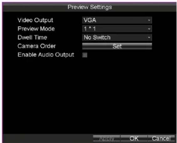
text_image
Preview Settings Video Output VGA Preview Mode 1 * 1 Dwell Time No Switch Camera Order Set Enable Audio Output Apply OK CancelFigure 7. 14 Preview Sengs
- Select the Video Output from the drop-down list according to the actual needs.
- Select the Preview Mode, Dwell Time for live view,
- Check the checkbox of Enable Audio Output to enable the funcon.
● Preview Mode: select the window division mode for live view.
● Dwell Time: the switch interval of the live view screen. The screen will be switched to the next one aer the selected dwell me.
● Enable Audio Output: Enables/disables audio output for the selected video output.
- Click the Set buon to set the Camera Order.
Perform the following steps to set the camera order for display:
1) Click and to adjust display channel for each window.

The character "X" means no camera will be displayed on the selected window.
2) Click OK to save the new sengs and exit.
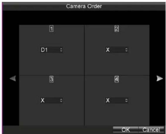
text_image
Camera Order 1 2 D1 X 3 4 X X OK CancelFigure 7. 15 Camera Order
- Click the Apply buon to save the new sengs and click OK to exit.
7.5 Alarm Sengs
Purpose:
You can congregate handling method for alarm events.
7.5.1 Excepon Sengs
Purpose:
Excepon Sengs refer to the handling methods of various excepons, e.g.
● HDD Full: The HDD is full.
- HDD Error: Wring HDD error, unformaed HDD, etc.
● Network Disconnected: Network cable is disconnected.
● IP Conicted: Duplicated IP address.
- Illegal Login: Incorrect user id or password.
● Video Excepon: frame rate is too low.
● Abnormal Recording: No space for saving recorded les.
Steps:
- Enter the Excepon interface.
Main Menu > Other Sengs > Excepon - Select the Excepon Type.
- Set the alarm linkage acons, including Audible Warning and Alarm Output.
- Click Apply to save the new sengs and click OK to exit.

text_image
Exception Exception Type HDD Full ■ Audio Warning Trigger Alarm Output All 1 2 Apply OK CancelFigure 7. 16 Excepon
7.5.2 Alarm Input Sengs
Purpose:
Congure the sengs for alarm input, including trigger level, arming schedule, alarm linkage acons, etc.
Steps:
- Enter the Alarm Input Sengs interface.
Main Menu > Other Sengs > AlarmIn

text_image
Alarm Input Settings Alarm Input No. A<-1 Alarm Name Alarm Type NO Trig Record Channel Set Schedule Set Handle Type Set Copy To All Copy Apply OK CancelFigure 7.17 Alarm Input Sengs
- Select the Alarm Input No..
- Input the Alarm Name as desired in the text eld.
- Set the Alarm Type as NO (Normally Open) or NC (Normally Closed) of the alarm input according to the actual needs.
- Click the Set buon of Trig Record Channel to select the alarm triggered recording channel(s). The selected channel(s) will start to record when a connected alarm input occurs.
- To congregate the Schedule, do following steps:
1) Click the Set buon of Schedule to set the arming schedule for alarm inputs.
2) Oponally, you can click Copy to copy the current sengs to other days in the week.

Up to 8 me periods can be set within each day. And the me periods can't be overlapped each other.
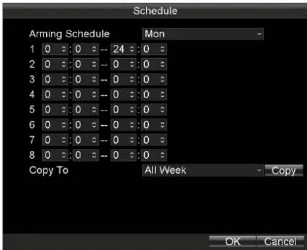
Figure 7.18 Arming Schedule
- Check the checkbox of Handle Type and click the corresponding Set buon, and you can congregate the alarm linkage acons, including Pop-up Image on Monitor, Audio Warning and Trigger Alarm Output.
➢ Pop-up Image on Monitor
When an alarm is triggered, the local monitor displays the video image from the alarming channel congured for full screen monitoring.
Audio Warning:
Trigger an audible beep when an alarm input is detected.
Trigger Alarm Output:
Trigger an alarm output when an alarm when an alarm input is detected.

text_image
Handle Type ■ Pop-up Image On Monitor ■ Audio Warning All 1 2 ■ Trigger Alarm Output OK CancelFigure 7. 19 Alarm Linkage Acon
- Click Apply to save the new sengs and click OK to exit.
7.5.3 Alarm Output Sengs
Purpose:
You can congregate the arming schedule, alarm duraon me, alarm name for alarm output.
Steps:
- Enter the Alarm Output Sengs interface.
Main Menu > Other Sengs > AlarmOut

text_image
Alarm Output Settings Alarm Output No. A->1 Alarm Name Duration 5s Arming Schedule Set Copy To All Copy Apply OK CancelFigure 7. 20 Alarm Output Sengs
- Select the Alarm Output No..
- Input the Alarm Name as desired in the text eld.
4. Set the Alarm Duraon me.
5. To set Alarm Schedule, do following steps:
1) Click the Set buon of Schedule to set the arming schedule for alarm outputs.

Up to 8 me periods can be set within each day. And the me periods can't be overlapped with each other.
2) Oponally, you can click Copy to copy the current sengs to other days in the week.

Figure 7.21 Arming Schedule Sengs
- Oponally, you can click Copy to copy the current sengs to other alarm output.
- Click Apply to save the new sengs and click OK to exit.
7.6 Firewall Sengs
Purpose:
The Rail NVR provides soware-based rewall to protect the device against the threats from the public network.
A white list can be set, and only the trusted IP addresses on the white list can access the device via the network.

● 192.0.0.xxx are set as the default trusted IP addresses.
● The IP address of the plaorm server to add the device is set as the trusted IP address.
- Up to 16 IP addresses can be added on the white list.
Steps:
- Enter the Firewall Sengs interface.
Main Menu > Other Sengs > Firewall

text_image
Firewall Settings ■ Enable SSH Service ✓ Enable White List Clear All No. IP Add Delete OK CancelFigure 7.22 Firewall Sengs
- Oponally, you can select Enable SSH Service, thus to eecvely prevent informaon leakage during remote management.
- Click the Add buon to enter the Add IP Address dialog box, input the trusted IP address, and click OK.
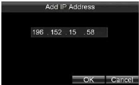
text_image
Add IP Address 196 . 152 . 15 . 58 OK CancelFigure 7. 23 Add IP Address
- The trusted IP address will be added on the white list.

text_image
Firewall Settings ■ Enable SSH Service ✓ Enable White List Clear All No: IP 1 196.152.15.58 Add Delete OK CancelFigure 7. 24 White List Sengs

The congured white list will be cleared aer you reboot the device.
- To delete the trusted IP address, you can select it on the white list and then click the Delete buon.
Or you can also click the Clean All buon to clear all the trusted IP address on the white list.
7.7 PTZ Sengs
Purpose:
Follow the procedure to set the parameters for PTZ. The conguring of the PTZ parameters should be done before you control the PTZ camera.
Before you start:
Connect the RS-485 cables of PTZ camera to EXT.DEV interface of the Rail NVR.
7.7.1 Conguring PTZ Parameters
Steps:
- Enter the PTZ Sengs interface.
Main Menu > Other Sengs > PTZ

text_image
PTZ Settings Camera IP Camera 1 Baudrate 9600 Data Bit 8 Stop Bit 1 Parity None Flow Ctrl None PTZ Protocol PELCO-D Address 1 Copy To All Copy Apply OK CancelFigure 7. 25 PTZ Sengs
- Choose the camera for PTZ seng in the Camera drop-down list.
- Set the parameters of the PTZ camera.

All the parameters should be exactly the same as the PTZ camera's parameters.
- Click OK buon to save the sengs.
7.7.2 PTZ Control Panel
Purpose:
If the connected camera is a speed dome, you can rotate it to desired view.
Step:
In live view interface, right click a speed dome and click PTZ on the right-click menu to enter the PTZ Control panel.

text_image
Zoom Focus Iris Speed 3.0 Preset Pattern ExitFigure 7. 26 PTZ Control Panel
Table 7.2 Descripon of PTZ Control Panel
| Icon | Descripon | Icon | Descripon | Icon | Descripon |
 | Direcon buon and the auto-cycle buon |  | Zoom+/Focus+/Iris+ |  | Zoom-/Focus-/Iris- |
| Speed 3 | Moving speed | [XZHB] | Light on/o |  | Wiper on/o |
Chapter 8 HDD Sengs
Purpose:
You can inialize HDD and view HDD informaon.
text_image
HDD Management Overwrite Yes Hard Disk Hard Disk1 Property R/W Disk Number 1 Status Abnormal Free Space/Capacity 0MB / 953.87GB S.M.A.R.T Info View Format OK CancelFigure 8.1 HDD Management
8.1 Inializing the HDD
Purpose:
Inializaon will erase all data on the HDD.
Before you start:
Install at least one HDD on the Rail NVR for video data storage.
Steps:
- Enter the HDD Management interface.
Main Menu > HDD
text_image
HDD Management Overwrite Yes Hard Disk Hard Disk1 Property RW Disk Number 1 Status Abnormal Free Space/Capacity 0MB / 953.87GB S.M.A.R.T Info View Format OK CancelFigure 8.2 HDD Management
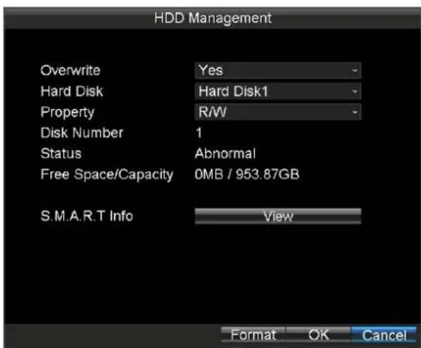
- Select the Hard Disk from the drop-down list.
- Click Format and click OK in popup conrmaon window.
8.2 Advanced HDD Sengs
Purpose:
You can enable/disable overwrite, congure the HDD property, and view the S.M.A.R.T informaon.
Steps:
- Select the Hard Disk to congregate in the drop-down list.
- Select Overwrite as Yes or No.
If Overwrite is set as Yes, data would keep wring into the HDD when HDD is full by replacing the previous data.
- Select Property as R/W or Redundancy.
● R/W: The HDD supports both read and wring operaon.
- Redundancy: Data would save in the R/W HDD as well as in the redundant HDD. Thus to eecvely enhance the data safety and reliability.
- To view HDD S.M.A.R.T informaon, do following steps:
1) Click View of S.M.A.R.T Info.
2) Select Hard Disk to view in the drop-down list.
3) Click Exit to exit the S.M.A.R.T informaon interface.
- Click OK to save the sengs.
Chapter 9 Status
Purpose:
You can view status for seven funcons.
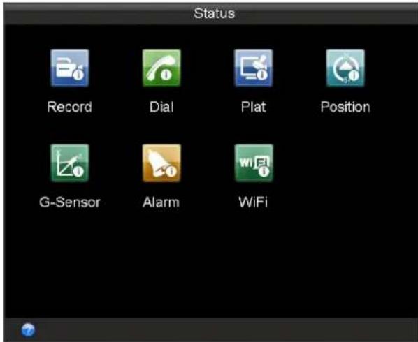
text_image
Status Record Dial Plat Position G-Sensor Alarm WiFiFigure 9.1 Status
Table 9.1 Sub-Menu Descripon
| Sub-Menu Name | Descripon |
| Record | Recording status of each IP camera is listed. |
| Dial | Dialing status and informaon is listed. |
| Plat | The current plaorm, login status, and excepon informaon are listed. |
| Posion | Posion status shows the posioning informaon and status. |
| G-Sensor | Vehicle’s acceleraon speed informaon in 3-axial (X, Y, Z) direcons. |
| Alarm | Whether alarm input/alarm output occurs is listed. |
| WiFi | Wi-Fil informaon is listed. |
9.1 Record Status
Purpose:
Recording status of each IP camera is listed.
Steps:
- Enter the Record Status interface.
Main Menu > Status > Record

icon represents the IP camera is recording.

icon represents it is not recording.
- To view record schedule, click Query.
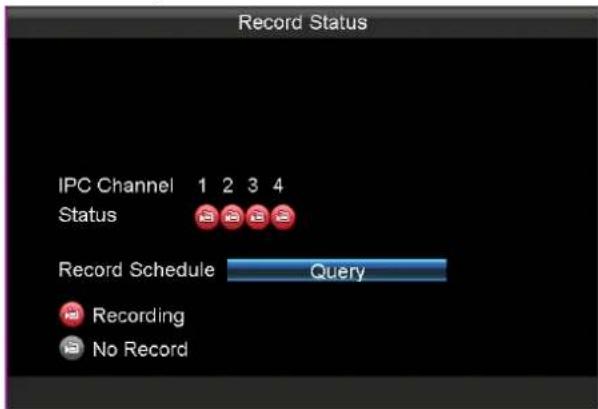
text_image
Record Status IPC Channel 1 2 3 4 Status Record Schedule Query Recording No RecordFigure 9.2 Record Status
9.2 Dialing Status
Purpose:
Dialing status and informaon is listed.
Steps:
- Enter the Dial interface.
Main Menu > Status > Dial
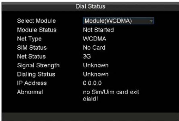
text_image
Dial Status Select Module Module(WCDMA) Module Status Not Started Net Type WCDMA SIM Status No Card Net Status 3G Signal Strength Unknown Dialing Status Unknown IP Address 0.0.0.0 Abnormal=no Sim/Uim card,exit diald!Figure 9.3 Dial Status
9.3 Plaorm Status
Purpose:
The current plaorm, login status, and excepon informaon are listed.
Step:
Enter the Plaorm interface.
Main Menu > Status > Plat

text_image
Platform Register Status Current Plat IVMS Login Status Login Succeeded Exception Info NoneFigure 9.4 Plaorm Registraon Status
9.4 Posion Status
Purpose:
Posion status shows the posioning informaon and status.
Step:
Enter the Plaorm interface.
Main Menu > Status > Posion
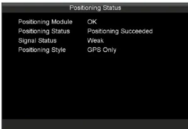
text_image
Positioning Status Positioning Module OK Positioning Status Positioning Succeeded Signal Status Weak Positioning Style GPS OnlyFigure 9.5 Posion Status
9.5 G-Sensor Status
Purpose:
Vehicle's acceleraon speed informaon in 3-axial (X, Y, Z) direcons.
Step:
Enter the Plaorm interface.
Main Menu > Status > G-Sensor
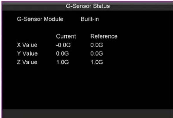
text_image
G-Sensor Status G-Sensor Module Built-in Current Reference X Value -0.0G 0.0G Y Value 0.0G 0.0G Z Value 1.0G 1.0GFigure 9. 6 G-Sensor Status
9.6 Alarm Status
Purpose:
Whether alarm input/alarm output occurs is listed.
Steps:
Enter the Plaorm interface.
Main Menu > Status > G-Sensor

icon represents alarm input/alarm output is occurring.

icon represents no alarm input/alarm output.

text_image
Alarm Status Alarm Input 1 2 3 4 5 6 7 8 Alarm Output 1 2 Channel Exist Alarm No AlarmFigure 9.7 Alarm Status
9.7 Wi-Fi Status
Purpose:
Wi-Fil informaon is listed.
Step:
Enter the Plaorm interface.
Main Menu > Status > G-Sensor

text_image
WiFi Status Enable Enable Status Connected Success SSID xyc Signal Strength Strong IP Address 192.168.43 162 AP List QueryFigure 9.8 Wi-Fi Status
Chapter 10 Maintenance
Purpose:
You can upgrade, search log, restore device, import/export conguraon le, view device informaon, initialize USB storage device, and reboot device.
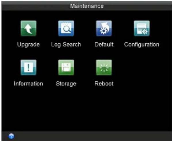
text_image
Maintenance Upgrade Log Search Default Configuration Information Storage RebootFigure 10.1 Maintenance
Table 10. 1 Sub-Menu Descripon
| Sub-Menu Name | Descripon |
| Upgrade | You can upgrade the Rail NVR via local USB ash disk or remote FTP server. |
| Log Search | You can view and export the operaon, alarm, excepon, and informaon log les |
| Default | You can restore Rail NVR to default sengs or factory sengs. |
| Conguraon | The conguraon les of the Rail NVR can be exported to local device for backup;and the conguraon les of one device can be imported to other devices if they are to be congured with the same parameters. |
| Informaon | You can view the system informaon including device name, model, serial No., rmware version, encoding version, and panel version. |
| Storage | You can view the status and the free space/capacity of the connected USB device. |
| Reboot | You can reboot system here. |
10.1 System Upgrade
Purpose:
The Rail NVR can be upgraded via local USB ash disk or remote FTP server. You're recommended to upgrade Rail NVR under the help of professional technical support.
10.1.1 Local USB Flash Disk Upgrade
Before you start:
Connect the USB device on which the upgrade rmware is stored to the Rail NVR.

The upgrade rmware should be stored in the root directory of the USB device.
Steps:
- Enter the Upgrade interface.
Main Menu > Maintenance > Upgrade
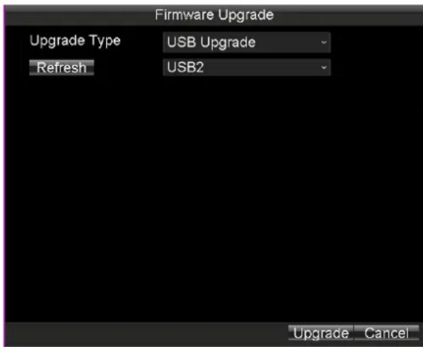
text_image
Firmware Upgrade Upgrade Type USB Upgrade Refresh USB2 Upgrade CancelFigure 10.2 Upgrade Interface
- Select Upgrade Type as USB Upgrade.
- Click Upgrade to start upgrading and reboot the device to acvate the new sengs.
10.1.2 Remote FTP Server Upgrade
Before you start:
Ensure the network conneccon of the PC (running FTP server) and the DVR is valid and correct. Run the FTP server on the PC and copy the rmware into the corresponding directory of your PC.

Refer to the user manual of the FTP server to set the FTP server on your PC and put the rmware le into the directory as required.
Steps:
- Enter the Upgrade interface.
Main Menu > Maintenance > Upgrade
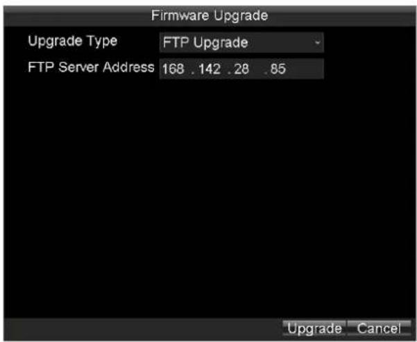
text_image
Firmware Upgrade Upgrade Type FTP Upgrade FTP Server Address 168 .142 .28 .85 Upgrade CancelFigure 10.3 Upgrade Interface
- Select the Upgrade Type as FTP Upgrade.
- Input the FTP Server Address in the text eld.
- Click Upgrade to start upgrading and reboot the device to acvate the new sengs.
10.2 Log Search and Export
Purpose:
The operaon, alarm, excepon, and informaon of the device can be stored in log les, which can be viewed and exported at any me.
Steps:
- Enter the Log Search interface.
Main Menu > Maintenance > Log Search

Figure 10.4 Log Search Interface
- Select the Major Type of the logs from the drop-down list, including Alarm, Excepon, Operaon, and Informaon. You can also select All as the major type to search all the logs.
- Select the Minor Type of the logs under the selected major type.
-
Specify the Start Time and End Time for the log search.
-
Click the Search buon. The logs matching the search conditions will be displayed on a list.

text_image
Log Search Major Type Record Time Minor Type Parameter Operati... 03-14-2016 08:59:57 Power On N/A Inform... 03-14-2016 08:59:58 Local HDD Inf... N/A Excepti... 03-14-2016 09:00:01 HDD Error N/A Operati... 03-14-2016 09:00:02 Local Login N/A Excepti... 03-14-2016 09:00:34 IP Camera Co... N/A Inform... 03-14-2016 09:30:47 Start Record N/A Operati... 03-14-2016 09:31:22 Local Playbac... N/A Operati... 03-14-2016 09:38:14 Local Playbac... N/A Operati... 03-14-2016 09:39:03 Local Playbac... N/A Operati... 03-14-2016 09:39:07 Local Playbac... N/A Operati... 03-14-2016 09:39:12 Local Playbac... N/A Operati... 03-14-2016 09:39:35 Local Video Ex... N/A Operati... 03-14-2016 09:41:48 Local Playbac... N/A Operati... 03-14-2016 09:59:48 Shutdown Ab... N/A Details Play Export CancelFigure 10.5 Log Search Results
- To view the detailed informaon of the selected log, double click a log, or select the log item and then click Details.
- Select the log item, and then click Play to play the related videos (If there is any video related).
- Connect the USB device to the enforcement host, and then click Export to export the log le to the USB device for backup.
10.3 Restoring System
Purpose:
You can restore Rail NVR to default sengs or factory sengs.
Steps:
- Enter the Default interface.
Main Menu > Maintenance > Default
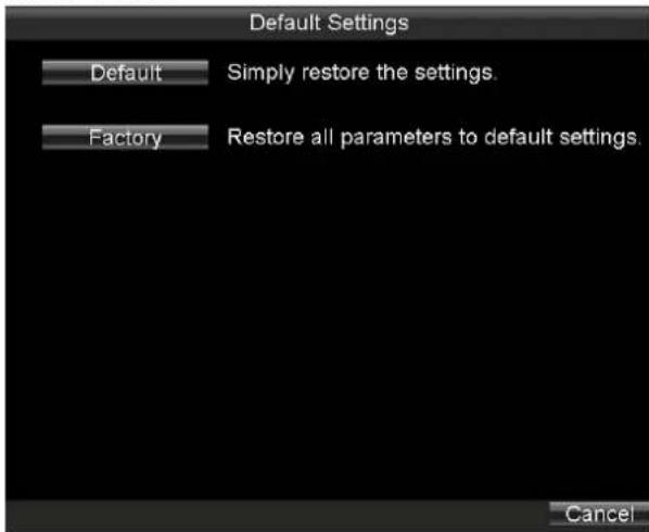
text_image
Default Settings Default Simply restore the settings. Factory Restore all parameters to default settings. CancelFigure 10.6 Restore Default Sengs
- Select the restoring type from the following two opons.
● Default: Restore all parameters, except the network (including IP address, subnet mask, gateway, MTU,
NIC working mode, default route, server port, etc.) and user account parameters, to the factory default sengs.
● Factory: Restore all parameters to the factory default sengs.
- Click the OK buon to restore the default sengs.
10.4 Imporng/Exporng Conguraon Files
Purpose:
The conguraon les of the Rail NVR can be exported to local device for backup; and the conguraon les of one device can be imported to other devices if they are to be congured with the same parameters.
Before you start:
Connect a USB storage device to the Rail NVR.
Steps:
- Enter the Import/Export Conguraon Files interface.
Main Menu > Maintenance > Conguraon
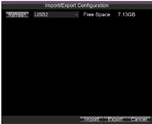
text_image
Import/Export Configuration Refresh USB2 Free Space 7.13GB Import Export CancelFigure 10.7 Import/Export Conguraon Files
- You can export or import conguraon les.
● To export the conguraon le, do following step:
Click the Export buon to export conguraon les to the USB device.
- To import the conguraon le, do following steps:
1) Connect a USB device in which the conguraon le is stored to the Rail NVR.

The conguraon le should be stored on the root directory of the USB device.
2) Click the Import buon.
3) Reboot the device to acvate the new sengs aer the imporg process is complete.
10.5 Viewing System Informaon
Purpose:
You can view the system informaon including device name, model, serial No., rmware version, encoding version, and panel version.
Step:
Enter the System Informaon interface.
Main Menu > Maintenance > Informaon
10.6 Storage
Purpose:
You can view the status and the free space/capacity of the connected USB storage device. And you can also format the USB storage device if needed.
Steps:
- Enter the Backup Device interface.
Main Menu > Maintenance > Storage

text_image
Backup Medium Backup Device USB1 Backup Status Normal Free Space/Capacity 7.11GB / 7.26GB Format OK CancelFigure 10. 8 Backup Device Interface
- Select the Backup Device from the drop-down list, and you can view the status and the Free Space/Capacity of the backup device.
- Click Format, and you can format the selected USB storage device.
Chapter 11 Shutdown and Reboot
11.1 Shutdown
Steps:
-
Insert the key into the Lock slot in front panel.
-
To shut down device, rotate it from ☐ to ☐
11.2 Reboot
Steps:
- Enter Reboot interface.
Main Menu > Maintenance > Reboot
-
Click Maintenance to enter Maintenance menu.
-
Click Reboot and click Yes in popup dialog box to reboot device.
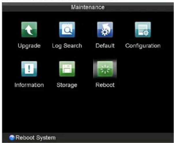
text_image
Maintenance Upgrade Log Search Default Configuration Information Storage Reboot Reboot SystemFigure 11.1 Reboot Device
Appendix I Specicaons
| No. | Name | Descripon |
| 1 | GNSS | GNSS antenna interface |
| WIFI | Wi-Fi antenna interface. (only supported by the "/GW" devices) | |
| M-ANT | 3G antenna interface | |
| 2 | IR | IR: IR receiverReceive IR signal from remote control. |
| 3 | Indicators | PWR: Power indicatorTurns green aer device starts up; Turns red when device stands by. |
| RDY: Ready indicatorTurns green when the device starts up | ||
| REC: Record indicatorTurns green when recording; The light is out when all recording processes are abnormal. | ||
| GNSS: GNSS indicatorNo light when GNSS module is abnormal; Turns green when the GNSS module works normally; Blinks in green aer the posioning successful. | ||
| ANT: 3G indicatorTurns green when 3G module works normally; Blinks slowly in 3G registraon;Blinks frequently aer successful 3G registraon. | ||
| ALM: Alarm indicatorTurns red when alarm occurs. | ||
| 4 | SIM | SIM card slot. |
| 5 | LAN1 | RJ45 network interface for debugging. |
| 6 | USB1 | USB 3.0 interface. |
| USB2 | ||
| 7 | Alarm OUT | 2-ch relay signal output. |
| RS-485 | RS-485 interface | |
| Alarm IN | 8-ch relay signal input. | |
| 8 | VGA | VGA output. |
| 9 | RS232 | Serial interface. |
| 10 | A OUT | Audio output. |
| 11 | V OUT | Video output. |
| 12 | LINE | Two-way audio input. |
| 13 | LAN2 | M12 network interface for connecng IP cameras. |
| 14 | 110 VDC | Power supply. |
| 15 | Lock | Hard drive lock. |
| 16 | Hard Drive Enclosure | 3 hard drive caddies for 2.5 inch SATA HDDs/SSDs |
Appendix II List of Compatible IP Camera
| Model | Version | Max. Resoluon | Sub-stream | Audio |
| DS-2CD6510DT-I(O) | V5.4.0 Build 160401 | 1280 × 960 | √ | √ |
| DS-2CD6520DT-I(O) | 1920 × 1080 | √ | √ | |
| DS-2CD6510D-I(O) | 1280 × 960 | √ | √ | |
| DS-2CD6520D-I(O) | 1920 × 1080 | √ | √ | |
| DS-2CD6520ET-IO | 1920 × 1080 | √ | × | |
| DS-2CD6510ET-IO | 1280 × 960 | √ | × | |
| DS-2CD6533BT | V5.1.0 Build 150512 | 2048 × 1536 | √ | × |
| DS-2CD6562PT | V5.0.9 Build 150901 | 3072 × 2048 | √ | × |
| DS-2CD6332FWD-I | V5.3.5 Build20160106 | 2048 × 1536 | √ | √ |
| DS-2CD6362FWD-I | 3072 × 2048 | √ | √ |

text_image
FirstFirst Choice for Security Professionals