iDS-9632NXI-I16/8F(B) - Video Surveillance System Hikvision - Free user manual and instructions
Find the device manual for free iDS-9632NXI-I16/8F(B) Hikvision in PDF.

User questions about iDS-9632NXI-I16/8F(B) Hikvision
0 question about this device. Answer the ones you know or ask your own.
Ask a new question about this device
Download the instructions for your Video Surveillance System in PDF format for free! Find your manual iDS-9632NXI-I16/8F(B) - Hikvision and take your electronic device back in hand. On this page are published all the documents necessary for the use of your device. iDS-9632NXI-I16/8F(B) by Hikvision.
USER MANUAL iDS-9632NXI-I16/8F(B) Hikvision
natural_image
Abstract red geometric shape with a white diagonal stripe on the left (no text or symbols)Network Video Recorder
User Manual
Legal Information
About this Manual
The Manual includes instructions for using and managing the Product. Pictures, charts, images and all other information hereinafter are for description and explanation only. The information contained in the Manual is subject to change, without notice, due to firmware updates or other reasons. Please find the latest version of this Manual at the company website Please use this Manual with the guidance and assistance of professionals trained in supporting the Product.
Trademarks Acknowledgement
Trademarks and logos mentioned are the properties of their respective owners.

HIGH-DEFINITION MULTIMEDIA INTERFACE
The terms HDMI and HDMI High-Definition Multimedia Interface, and the HDMI Logo are trademarks or registered trademarks of HDMI Licensing Administrator, Inc. in the United States and other countries.
LEGAL DISCLAIMER
TO THE MAXIMUM EXTENT PERMITTED BY APPLICABLE LAW, THIS MANUAL AND THE PRODUCT DESCRIBED, WITH ITS HARDWARE, SOFTWARE AND FIRMWARE, ARE PROVIDED "AS IS" AND "WITH ALL FAULTS AND ERRORS". OUR COMPANY MAKES NO WARRANTIES, EXPRESS OR IMPLIED, INCLUDING WITHOUT LIMITATION, MERCHANTABILITY, SATISFACTORY QUALITY, OR FITNESS FOR A PARTICULAR PURPOSE. THE USE OF THE PRODUCT BY YOU IS AT YOUR OWN RISK. IN NO EVENT WILL OUR COMPANY BE LIABLE TO YOU FOR ANY SPECIAL, CONSEQUENTIAL, INCIDENTAL, OR INDIRECT DAMAGES, INCLUDING, AMONG OTHERS, DAMAGES FOR LOSS OF BUSINESS PROFITS, BUSINESS INTERRUPTION, OR LOSS OF DATA, CORRUPTION OF SYSTEMS, OR LOSS OF DOCUMENTATION, WHETHER BASED ON BREACH OF CONTRACT, TORT (INCLUDING NEGLIGENCE), PRODUCT LIABILITY, OR OTHERWISE, IN CONNECTION WITH THE USE OF THE PRODUCT, EVEN IF OUR COMPANY HAS BEEN ADVISED OF THE POSSIBILITY OF SUCH DAMAGES OR LOSS.
YOU ACKNOWLEDGE THAT THE NATURE OF THE INTERNET PROVIDES FOR INHERENT SECURITY RISKS, AND OUR COMPANY SHALL NOT TAKE ANY RESPONSIBILITIES FOR ABNORMAL OPERATION, PRIVACY LEAKAGE OR OTHER DAMAGES RESULTING FROM CYBER-ATTACK, HACKER ATTACK, VIRUS INFECTION, OR OTHER INTERNET SECURITY RISKS; HOWEVER, OUR COMPANY WILL PROVIDE TIMELY TECHNICAL SUPPORT IF REQUIRED.
YOU AGREE TO USE THIS PRODUCT IN COMPLIANCE WITH ALL APPLICABLE LAWS, AND YOU ARE SOLELY RESPONSIBLE FOR ENSURING THAT YOUR USE CONFORMS TO THE APPLICABLE LAW. ESPECIALLY, YOU ARE RESPONSIBLE, FOR USING THIS PRODUCT IN A MANNER THAT DOES NOT INFRINGE ON THE RIGHTS OF THIRD PARTIES, INCLUDING WITHOUT LIMITATION, RIGHTS OF PUBLICITY, INTELLECTUAL PROPERTY RIGHTS, OR DATA PROTECTION AND OTHER PRIVACY RIGHTS. YOU SHALL NOT USE THIS PRODUCT FOR ANY PROHIBITED END-USES, INCLUDING THE DEVELOPMENT OR PRODUCTION OF WEAPONS OF MASS DESTRUCTION, THE DEVELOPMENT OR PRODUCTION OF CHEMICAL OR BIOLOGICAL WEAPONS, ANY ACTIVITIES IN THE CONTEXT RELATED
TO ANY NUCLEAR EXPLOSIVE OR UNSAFE NUCLEAR FUEL-CYCLE, OR IN SUPPORT OF HUMAN RIGHTS ABUSES. IN THE EVENT OF ANY CONFLICTS BETWEEN THIS MANUAL AND THE APPLICABLE LAW, THE LATER PREVAILS.
Regulatory Information
FCC Information
Please take attention that changes or modification not expressly approved by the party responsible for compliance could void the user's authority to operate the equipment.
FCC compliance: This equipment has been tested and found to comply with the limits for a Class A digital device, pursuant to part 15 of the FCC Rules. These limits are designed to provide reasonable protection against harmful interference when the equipment is operated in a commercial environment. This equipment generates, uses, and can radiate radio frequency energy and, if not installed and used in accordance with the instruction manual, may cause harmful interference to radio communications. Operation of this equipment in a residential area is likely to cause harmful interference in which case the user will be required to correct the interference at his own expense.
FCC Conditions
This device complies with part 15 of the FCC Rules. Operation is subject to the following two conditions:
-
This device may not cause harmful interference.
-
This device must accept any interference received, including interference that may cause undesired operation.
EU Conformity Statement

This product and - if applicable - the supplied accessories too are marked with "CE" and comply therefore with the applicable harmonized European standards listed under the EMC Directive 2014/30/EU, the RoHS Directive 2011/65/EU.

2012/19/EU (WEEE directive): Products marked with this symbol cannot be disposed of as unsorted municipal waste in the European Union. For proper recycling, return this product to your local supplier upon the purchase of equivalent new equipment, or dispose of it at designated collection points. For more information see: http://www.recyclethis.info.

2006/66/EC (battery directive): This product contains a battery that cannot be disposed of as unsorted municipal waste in the European Union. See the product documentation for specific battery information. The battery is marked with this symbol, which may include lettering to indicate cadmium (Cd), lead (Pb), or mercury (Hg). For proper recycling, return the battery to your supplier or to a designated collection point. For more information see: http://www.recyclethis.info .
Industry Canada ICES-003 Compliance
This device meets the CAN ICES-3 (A)/NMB-3(A) standards requirements.
Applicable Model
This manual is applicable to the following models.
Table 1-1 Applicable Model
| Series Model | |
| iDS-6700NXI-I/8F(B) iDS-6708NXI-I/8F(B) | |
| iDS-6716NXI-I/16S(B) iDS-6716NXI-I/16S(B) | |
| iDS-7700NXI-I4/16P/16S(B) iDS-7716NXI-I4/16P/16S(B) | iDS-7732NXI-I4/16P/16S(B) |
| iDS-7700NXI-I4/16P/X(B) iDS-7716NXI-I4/16P/X(B) | iDS-7732NXI-I4/16P/X(B) |
| iDS-7700NXI-I4/16S(B) iDS-7716NXI-I4/16S(B) | iDS-7732NXI-I4/16S(B) |
| iDS-7700NXI-I4/X(B) iDS-7716NXI-I4/X(B) | iDS-7732NXI-I4/X(B) |
| iDS-9600NXI-I8/4F(B) iDS-9608NXI-I8/4F(B) | iDS-9616NXI-I8/4F(B) |
| iDS-9632NXI-I8/4F(B) | |
| iDS-9600NXI-I8/8F(B) iDS-9616NXI-I8/8F(B) | iDS-9632NXI-I8/8F(B) |
| iDS-9664NXI-I8/8F(B) | |
| iDS-9600NXI-I8/X(B) iDS-9616NXI-I8/X(B) | iDS-9632NXI-I8/X(B) |
| iDS-9664NXI-I8/X(B) | |
| iDS-9600NXI-I8/16S(B) iDS-9616NXI-I8/16S(B) | iDS-9632NXI-I8/16S(B) |
| iDS-9664NXI-I8/16S(B) | |
| iDS-9600NXI-I16/8F(B) iDS-9616NXI-I16/8F(B) | iDS-9632NXI-I16/8F(B)iDS-9664NXI-I16/8F(B) |
| iDS-9600NXI-I16/X(B) iDS-9616NXI-I16/X(B) | |
| iDS-9632NXI-I16/X(B) | |
| iDS-9664NXI-I16/X(B) | |
| iDS-9600NXI-I16/16S(B) iDS-9616NXI-I16/16S(B) | |
| iDS-9632NXI-I16/16S(B) | |
| iDS-9664NXI-I16/16S(B) | |
| iDS-96000NXI-I16(B) iDS-96064NXI-I16(B) | |
| iDS-96128NXI-I16(B) | |
| iDS-96000NXI-I24(B) iDS-96128NXI-I24(B) | |
| iDS-96256NXI-I24(B) |
Symbol Conventions
The symbols that may be found in this document are defined as follows.
| Symbol Description | |
 Danger Danger | Indicates a hazardous situation which, if not avoided, will or could result in death or serious injury. |
 Caution Caution | Indicates a potentially hazardous situation which, if not avoided, could result in equipment damage, data loss, performance degradation, or unexpected results. |
 Note Note | Provides additional information to emphasize or supplement important points of the main text. |
Safety Instruction
- Proper configuration of all passwords and other security settings is the responsibility of the installer and/or end-user.
- In the use of the product, you must be in strict compliance with the electrical safety regulations of the nation and region.
- Firmly connect the plug to the power socket. Do not connect several devices to one power adapter. Power off the device before connecting and disconnecting accessories and peripherals.
- Shock hazard! Disconnect all power sources before maintenance.
- The equipment must be connected to an earthed mains socket-outlet.
- The socket-outlet shall be installed near the equipment and shall be easily accessible.
- 12 indicates hazardous live and the external wiring connected to the terminals requires installation by an instructed person.
- Never place the equipment in an unstable location. The equipment may fall, causing serious personal injury or death.
- Input voltage should meet the SELV (Safety Extra Low Voltage) and the LPS (Limited Power Source) according to the IEC60950-1.
• High touch current! Connect to earth before connecting to the power supply. - If smoke, odor or noise rise from the device, turn off the power at once and unplug the power cable, and then please contact the service center.
- Use the device in conjunction with an UPS, and use factory recommended HDD if possible.
- This product contains a coin/button cell battery. If the battery is swallowed, it can cause severe internal burns in just 2 hours and can lead to death.
- This equipment is not suitable for use in locations where children are likely to be present.
- CAUTION: Risk of explosion if the battery is replaced by an incorrect type.
- Improper replacement of the battery with an incorrect type may defeat a safeguard (for example, in the case of some lithium battery types).
- Do not dispose of the battery into fire or a hot oven, or mechanically crush or cut the battery, which may result in an explosion.
- Do not leave the battery in an extremely high temperature surrounding environment, which may result in an explosion or the leakage of flammable liquid or gas.
- Do not subject the battery to extremely low air pressure, which may result in an explosion or the leakage of flammable liquid or gas.
- Dispose of used batteries according to the instructions.
- Keep body parts away from fan blades and motors. Disconnect the power source during servicing.
- Keep body parts away from motors. Disconnect the power source during servicing.
Preventive and Cautionary Tips
Before connecting and operating your device, please be advised of the following tips:
- The device is designed for indoor use only. Install it in a well-ventilated, dust-free environment without liquids.
- Ensure recorder is properly secured to a rack or shelf. Major shocks or jolts to the recorder as a result of dropping it may cause damage to the sensitive electronics within the recorder.
- The equipment shall not be exposed to dripping or splashing and that no objects filled with liquids shall be placed on the equipment, such as vases.
- No naked flame sources, such as lighted candles, should be placed on the equipment.
- The ventilation should not be impeded by covering the ventilation openings with items, such as newspapers, table-cloths, curtains, etc. The openings shall never be blocked by placing the equipment on a bed, sofa, rug or other similar surface.
- For certain models, ensure correct wiring of the terminals for connection to an AC mains supply.
- For certain models, the equipment has been designed, when required, modified for connection to an IT power distribution system.
- ☐ identifies the battery holder itself and identifies the positioning of the cell(s) inside the battery holder.
- + identifies the positive terminal(s) of equipment which is used with, or generates direct current. + identifies the negative terminal(s) of equipment which is used with, or generates direct current.
- Keep a minimum 200 mm (7.87 inch) distance around the equipment for sufficient ventilation.
- For certain models, ensure correct wiring of the terminals for connection to an AC mains supply.
- Use only power supplies listed in the user manual or user instruction.
- The USB port of the equipment is used for connecting to a mouse, keyboard, USB flash drive, or Wi-Fi dongle only.
- Use only power supplies listed in the user manual or user instruction.
- Do not touch the sharp edges or corners.
Contents
Chapter 1 Basic Operation .... 1
Chapter 4 Recording and Playback .... 38
4.1 Recording 38
4.1.1 Configure Recording Parameters 38
4.1.2 Enable the H.265 Stream Access 40
4.1.3 ANR 40
4.1.4 Manual Recording 40
4.1.5 Configure Plan Recording 41
4.1.6 Configure Continuous Recording 42
4.1.7 Configure Motion Detection Triggered Recording 43
4.1.8 Configure Event Triggered Recording 43
4.1.9 Configure Alarm Triggered Recording 43
4.1.10 Configure Picture Capture 44
4.1.11 Configure Holiday Recording 44
4.1.12 Configure Redundant Recording and Capture 45
4.2 Playback 46
4.2.1 Instant Playback 46
4.2.2 Play Normal Video 47
4.2.3 Play Smart Searched Video 48
4.2.4 Play Custom Searched Files 48
4.2.5 Play Tag Files 49
4.2.6 Play by Sub-periods 50
4.2.7 Play Log Files 51
4.2.8 Play External Files 51
4.3 Playback Operations 52
4.3.1 Normal/Important/Custom Video 52
4.3.2 Set Play Strategy in Important/Custom Mode 52
4.3.3 Edit Video Clips 52
4.3.4 Switch between Main Stream and Sub-Stream 53
4.3.5 Thumbnails View 53
4.3.6 Fisheye View 53
4.3.7 Fast View 54
4.3.8 Digital Zoom 54
Chapter 5 Event ...... 56
5.1 Normal Event Alarm 56
5.1.1 Configure Motion Detection Alarms 56
5.1.2 Configure Video Loss Alarms 56
5.1.3 Configure Video Tampering Alarms 57
5.1.4 Configure Sensor Alarms 57
5.1.5 Configure Exceptions Alarms 57
5.2 VCA Event Alarm 58
5.2.1 Temperature Screening 58
5.2.2 Loitering Detection 59
5.2.3 People Gathering Detection 60
5.2.4 Fast Moving Detection 61
5.2.5 Parking Detection 62
5.2.6 Unattended Baggage Detection 63
5.2.7 Object Removal Detection 64
5.2.8 Audio Exception Detection 65
5.2.9 Defocus Detection 66
5.2.10 Sudden Scene Change Detection 67
5.2.11 PIR Alarm 68
5.2.12 Thermal Camera Detection 69
5.2.13 Configure Queue Management 70
5.3 Configure Arming Schedule 70
5.4 Configure Linkage Actions 71
5.4.1 Configure Auto-Switch Full Screen Monitoring 71
5.4.2 Configure Audio Warning 72
5.4.3 Notify Surveillance Center 72
5.4.4 Configure Email Linkage 72
5.4.5 Trigger Alarm Output 73
5.4.6 Configure Audio and Light Alarm Linkage 73
5.4.7 Configure PTZ Linkage 73
Chapter 6 Smart Analysis ...... 75
6.1 Engine Configuration 75
6.2 Task Configuration 76
6.3 Face Picture Comparison 77
6.3.1 Face Grading Configuration 77
6.3.2 Face Capture 78
6.3.3 Face Picture Library Management 79
6.3.4 Face Picture Comparison Alarm 80
6.3.5 People Frequency Alarm 84
6.3.6 Face Picture Search 87
6.4 Perimeter Protection 90
6.4.1 Line Crossing Detection 90
6.4.2 Intrusion Detection 92
6.4.3 Region Entrance Detection 93
6.4.4 Region Exiting Detection 94
6.5 Human Body Detection 95
6.5.1 Human Body Detection 95
6.5.2 Human Body Search 96
6.6 Multi-Target-Type Detection 98
6.7 Vehicle Detection 99
6.7.1 Configure Vehicle Detection 99
6.7.2 Vehicle Search 100
6.8 TargetDetection 101
6.9 People Counting 102
6.10 Heat Map 102
Chapter 7 File Management .... 104
7.1 Search Files 104
7.2 Export Files 104
7.3 Smart Search 105
Chapter 8 Storage .... 106
8.1 Storage Device Management 106
8.1.1 SSD Management 106
8.1.2 Manage Local HDD 107
8.1.3 Add a Network Disk 109
8.1.4 Manage eSATA 110
8.2 Disk Array 112
8.2.1 Create a Disk Array 112
8.2.2 Rebuild an Array 114
Chapter 9 POS Configuration .... 117
9.1 Configure POS Connection 117
9.2 Configure POS Text Overlay 120
9.3 Configure POS Alarm 121
Chapter 10 Hot Spare Recorder Backup .... 123
10.1 Set Hot Spare Device 123
10.2 Set Working Recorder 124
10.3 Manage Hot Spare System 124
Chapter 11 Network Settings ...... 126
11.1 Configure DDNS 126
11.2 17.3 Configure PPPoE 126
11.3 Configure Port Mapping (NAT) 127
11.4 Configure SNMP 128
11.5 Configure Email 130
11.6 Configure Port 131
11.7 Configure ONVIF 133
Chapter 12 User Management and Security .... 134
12.1 Manage User Accounts 134
12.1.1 Add a User 134
12.1.2 Edit the Admin User .... 135
12.1.3 Edit an Operator/Guest User 136
12.2 Manage User Permissions 136
12.2.1 Set User Permissions 136
12.2.2 Set Live View Permission on Lock Screen 139
12.3 Configure Password Security 140
12.3.1 Export GUID File 140
12.3.2 Configure Security Questions 141
12.3.3 Configure Reserved Email 141
12.4 Reset Password 142
12.4.1 Reset Password by GUID 142
12.4.2 Reset Password by Security Questions 143
12.4.3 Reset Password by Reserved Email 143
12.4.4 Reset Password by Guarding Vision 144
Chapter 13 System Management .... 145
13.1 Configure Device 145
13.2 Configure Time 145
13.2.1 Manual Time Synchronization 146
13.2.2 NTP Synchronization 146
13.2.3 DST Synchronization 146
13.3 Network Detection 147
13.3.1 Network Traffic Monitoring 147
13.3.2 Test Network Delay and Packet Loss 147
13.3.3 Export Network Packet 148
13.3.4 Network Resource Statistics 148
13.4 Storage Device Maintenance 149
13.4.1 Bad Sector Detection 149
13.4.2 S.M.A.R.T. Detection 150
13.4.3 HDD Health Detection 151
13.4.4 Configure Disk Clone 151
13.4.5 Repair Database 152
13.5 Upgrade Device 153
13.5.1 Upgrade by Local Backup Device 153
13.5.2 Upgrade by FTP 153
13.5.3 Upgrade by Web Browser 154
13.5.4 Upgrade by Guarding Vision 154
13.6 Import/Export Device Configuration Files 155
13.7 Log Management 155
13.7.1 Log Storage 155
13.7.2 Search & Export Log Files 156
13.7.3 Upload Logs to the Server 157
13.7.4 One-Way Authentication 157
13.7.5 Two-WayAuthentication 158
13.8 Export Diagnostic Information 159
13.9 Restore Default Settings 159
13.10 Security Management 160
13.10.1 RTSP Authentication 160
13.10.2 ISAPI Service 161
13.10.3 HTTP Authentication 161
13.10.4 IP Camera Occupation Detection 162
Chapter 14 Appendix ...... 163
14.1 Glossary 163
14.2 Frequently Asked Questions 164
14.2.1 Why is there a part of channels displaying “No Resource” or turning black screen in multi-screen of live view? 164
14.2.2 Why is the video recorder notifying not support the stream type? 165
14.2.3 Why is the video recorder notifying risky password after adding network camera? 165
14.2.4 How to improve the playback image quality? 165
14.2.5 How to confirm the video recorder is using H.265 to record video? 165
14.2.6 Why is the timeline at playback not constant? 166
14.2.7 When adding network camera, the video recorder notifies network is unreachable. 166
14.2.8 Why is the IP address of network camera being changed automatically? ...... 166
14.2.9 Why is the video recorder notifying IP conflict? 166
14.2.10 Why is image getting stuck when the video recorder is playing back by single or multi-channel cameras? 167
14.2.11 Why does my video recorder make a beeping sound after booting? 167
14.2.12 Why is there no recorded video after setting the motion detection? 167
14.2.13 Why is the sound quality not good in recording video? 168
Chapter 1 Basic Operation
1.1 Activate Your Device
1.1.1 Default User and IP Address
- Default administrator account: admin.
- Default IPv4 address: 192.168.1.64.
1.1.2 Activate via Local Menu
For the first-time access, you need to activate the device by setting an admin password. No operation is allowed before activation. You can also activate the device via Web Browser, SADP or Client Software.
Steps
- Enter the admin password twice.
![admin ****** Weak ****** ✓ Export GUID ✓ Security Question Configuration ✓ Reserved E-mail Settings Create Channel Default Password Note:Valid password range [8-16]. You can use a combination of numbers, lowercase, uppercase and special character for your password with at least two kinds of them contained. OK](/content/2026/06/1194368/images/c44c6e6f47935d07ddb100ba59b781af2b6b981c1575f88305cc3bc2c53d6e17.jpg)
Figure 1-1 Activate via Local Menu

Warning
We highly recommend you to create a strong password of your own choosing (using a minimum of 8 characters, including at least three kinds of following categories: upper case letters, lower case letters, numbers, and special characters) in order to increase the security of your product.
And we recommend you change your password regularly, especially in the high security system, changing the password monthly or weekly can better protect your product.
-
Enter the password to activate the IP cameras.
-
Optional: Check Export GUID, Security Question Configuration, or Reserved E-mail Settings.
-
Click OK.

Note
• After the device is activated, you should properly keep the password.
- You can duplicate the password to the IP cameras that are connected with default protocol.
What to do next
- When you have enabled Export GUID, continue to export the GUID file to the USB flash driver for the future password resetting.
- When you have enabled Security Question Configuration, continue to set the security questions for the future password resetting.
- When you have enabled Reserved E-mail Settings, continue to set the reserved email for the future password resetting.
1.1.3 Activate via SADP
SADP software is used for detecting the online device, activating the device, and resetting its password.
Before You Start
Get the SADP software from the supplied disk or the official website, and install the SADP according to the prompts.
Steps
- Connect your video recorder power supply to an electrical outlet and turn on it.
- Run the SADP software to search the online recorders.
- Check the recorder status from the device list, and select the inactive recorder.
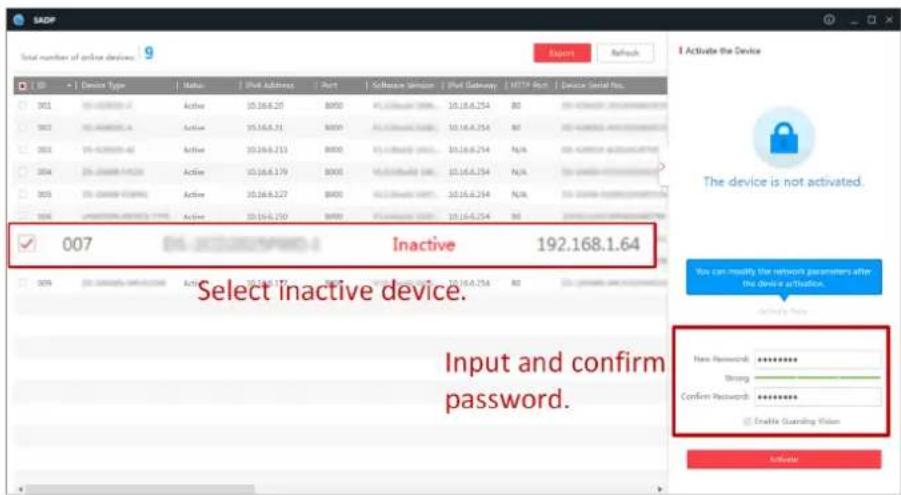
Figure 1-2 Activate via SADP
- Create and input the new password in the password field, and confirm the password.

Note
We highly recommend you to create a strong password of your own choosing (using a minimum of 8 characters, including at least three kinds of following categories: upper case letters, lower case letters, numbers, and special characters) in order to increase the security of your product. And we recommend you change your password regularly, especially in the high security system, changing the password monthly or weekly can better protect your product.
- Click Activate.
1.1.4 Activate via Client Software
The client software is versatile video management software for multiple kinds of devices.
Before You Start
Get the client software from the supplied disk or the official website, and install the software according to the prompts.
Steps
- Run the client software and the control panel of the software pops up, as shown below.
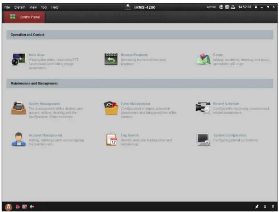
Figure 1-3 Control Panel
- Click Device Management to enter the Device Management interface, as shown below.
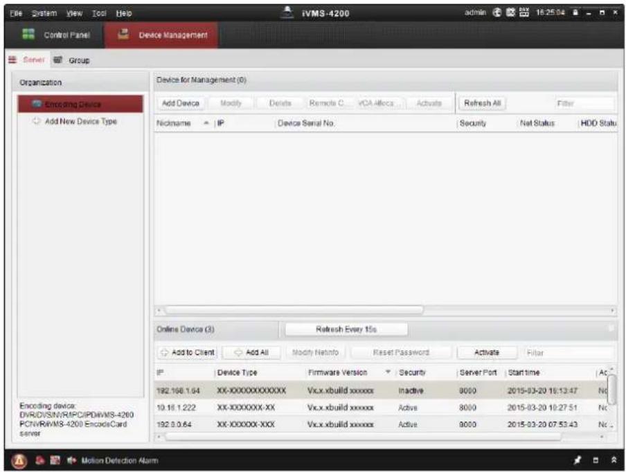
Figure 1-4 Device Management Interface
- Check the recorder status from the device list, and select an inactive recorder.
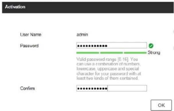
- Click Activate to pop up the Activation interface.
- Create a password and input the password in the password field, and confirm the password.

Note
We highly recommend you to create a strong password of your own choosing (using a minimum of 8 characters, including at least three kinds of following categories: upper case letters, lower case letters, numbers, and special characters) in order to increase the security of your product. And we recommend you change your password regularly, especially in the high security system, changing the password monthly or weekly can better protect your product.
![Activation User Name: admin Password: ••••••••• Strong Valid password range [8-16]. You can use a combination of numbers, lowercase, uppercase and special character for your password with at least two kinds of them contained. Confirm New Password: •••••••••• Ok Cancel](/content/2026/06/1194368/images/76634d45c2e7aadb854763ba6bbf3095f853b360e60935881aee2ec06efe7174.jpg)
Figure 1-5 Activation
- Click OK to start activation.
- Click Modify Netinfo to pop up the Network Parameter Modification interface, as shown below.
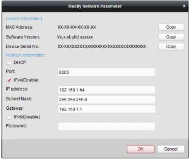
Figure 1-6 Modify Network Parameters
-
Change the recorder IP address to the same subnet with your computer.
-
Modify the IP address manually.
-
Check Enable DHCP.
-
Input the password to activate your IP address modification.
1.1.5 Activate via Web Browser
You can get access to the recorder via web browser. You may use one of the following listed web browsers: Internet Explorer 6.0 and above, Apple Safari, Mozilla Firefox, and Google Chrome. The supported resolutions include 1024*768 and above.
Steps
- Enter the IP address in web browser, and then press Enter.
- Set the password for the admin user account.
Note
We highly recommend you to create a strong password of your own choosing (using a minimum of 8 characters, including at least three kinds of following categories: upper case letters, lower case letters, numbers, and special characters) in order to increase the security of your product. And we recommend you change your password regularly, especially in the high security system, changing the password monthly or weekly can better protect your product.
- Click OK.
1.2 Configure TCP/IP Settings
TCP/IP settings must be properly configured before operating your over a network. Both IPv4 and IPv6 are available.
Steps
- Go to System → Network → TCP/IP.
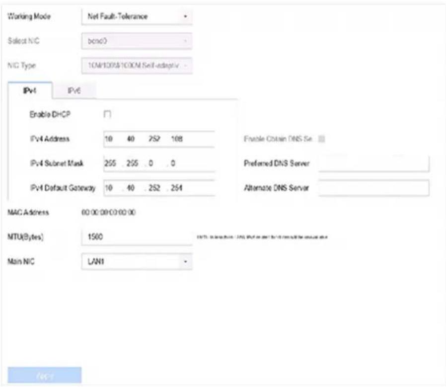
Figure 1-8 TCP/IP Settings
2. Select Working Mode as Net-Fault Tolerance or Multi-Address Mode.
Net-Fault Tolerance
The two NIC cards use the same IP address, and you can select the main NIC to LAN1 or LAN2. In this way, in case of one NIC card failure, the device will automatically enable the other standby NIC card so as to ensure the normal running of the system.
Multi-Address Mode
The parameters of the two NIC cards can be configured independently. You can select LAN1 or LAN2 under Select NIC for parameter settings. Select one NIC card as the default route. When the system connects with the extranet, the data will be forwarded through the default route.
-
Click IPv4 or IPv6 as you required.
-
Set related parameters.
-
Click Apply.

Note
- Check Enable DHCP to obtain IP settings automatically if a DHCP server is available on the network.
- Valid MTU value range is 500 to 9676.
1.3 HDD Settings
Ensure the video recorder storage media is well. You can install at least one HDD and initialize it, or create a RAID and initialize it.
1.4 Add Network Camera
Before you can get live video or record the video files, you must add the network cameras to the connection list of the device.
Before You Start
Ensure the network connection is valid and correct and the IP camera to add has been activated.
Steps
- Click □ on the main menu bar.
- Click Custom Add tab on the title bar.
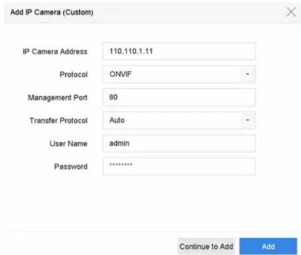
Figure 1-9 Add IP Camera
- Enter IP address, protocol, management port, and other IP camera information to add.
- Enter the login user name and password of the IP camera.
- Click Add to finish the adding of the IP camera.
- Optional: Click Continue to Add to continue to add additional IP cameras.
1.4.1 Add Automatically Searched Online Network Camera
Steps
- Click on the main menu.
- Click Number of Unadded Online Device at the bottom.
-
Select the automatically searched online network cameras.
-
Click Add to add the camera which has the same login password with the video recorder.
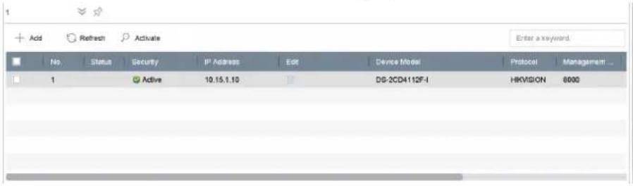
Figure 1-10 Add Automatically Searched Online Network Camera

Note
If the network camera to add has not been activated, you can activate it in the network camera list of camera management interface.
1.4.2 Add Network Camera Manually
Before you view live video or record video files, you must add network cameras to the device.
Before You Start
Ensure the network connection is valid and correct, and the network camera is activated.
Steps
- Click on the main menu.
- Click Custom Adding.
- Set IP Camera Address, Protocol, Management Port, Transfer Protocol, User Name, and Password. Management port ranges from 1 to 65535.
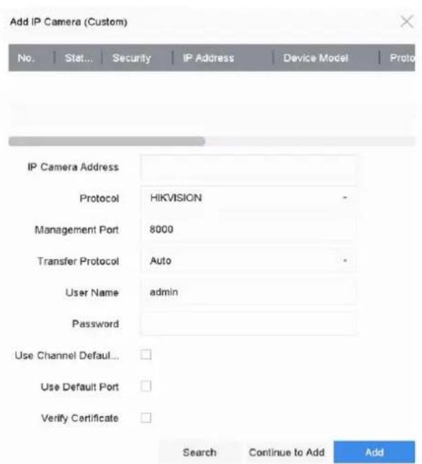
Figure 1-11 Add Network Camera
-
Optional: Check Use Channel Default Password to use the default password to add the camera.
-
Optional: Check Use Default Port to use the default management port to add the camera. For SDK service, the default port value is 8000. For enhanced SDK service, the default value is 8443.

Note
The function is only available when you use HIKVISION protocol.
- Optional: Check Verify Certificate to verify the camera with certificate. The certificate is a form of identification for the camera that provides more secure camera authentication. It requires to import the network camera certificate to the device first when you use this function. For details, refer to .

Note
The function is only available when you use HIKVISION protocol.
-
Click Add.
-
Optional: Check Continue to Add to add other network cameras.
1.4.3 Add Network Camera Through PoE
The PoE interfaces enable the device system to pass electrical power safely, along with data, on Ethernet cabling to the connected PoE cameras. Supported PoE camera number varies with device module. If you disable the PoE interface, you can also connect to the online network cameras. And the PoE interface supports the Plug-and-Play function.
Add PoE Camera
Steps
-
Go to Camera → Camera → PoE Settings.
-
Enable or disable long network cable mode by selecting Long Distance or Short Distance.
Long Distance
Long-distance (100 to 300 meters) network transmissions via PoE interface.
Short Distance
Short-distance (< 100 meters) network transmission via PoE interface.

Note
- The PoE ports are enabled with the short distance mode by default.
- The bandwidth of IP camera connected to the PoE via long network cable (100 to 300 meters) cannot exceed 6 MP.
- The allowed max. long network cable may be less than 300 meters depending on different IP camera models and cable materials.
- When the transmission distance reaches 100 to 250 meters, you must use the CAT5E or CAT6 network cable to connect with the PoE interface.
- When the transmission distance reaches 250 to 300 meters, you must use the CAT6 network cable to connect with the PoE interface.
- Refer to the Appendix 20.3 List of IP Cameras Connected to PoE by Long Network Cable (100 - 300 m) for the list of IP cameras.
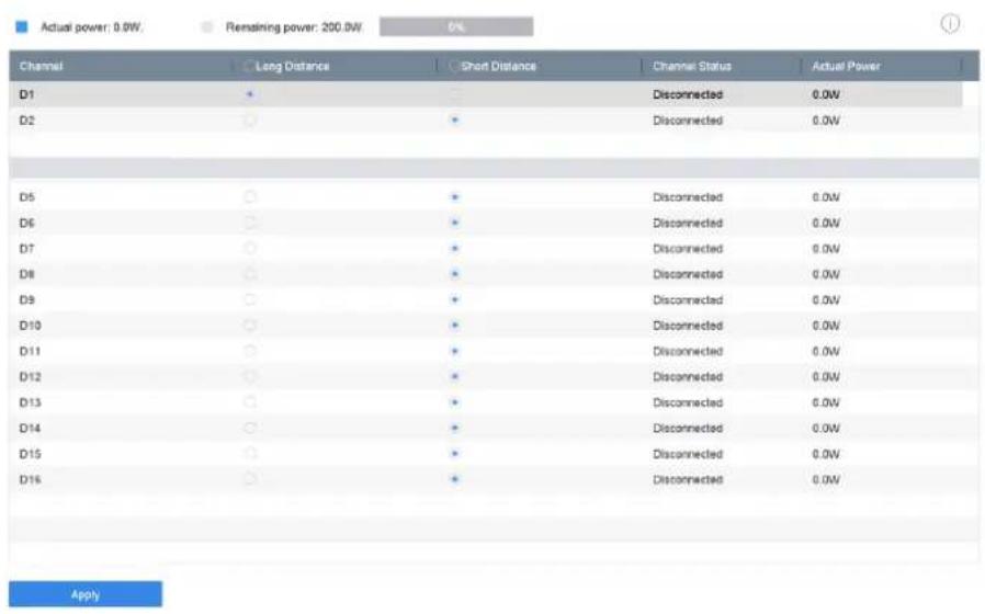
- Click Apply.
- Connect PoE cameras to device PoE ports with network cables.
- Go to Camera → Camera → IP Camera to view camera image and information.
Add Non-PoE Network Camera
You can disable the PoE interface by selecting the manual while the current channel can be used as a normal channel and the parameters can also be edited.
Steps
- Go to Camera → Camera → IP Camera.
- Position the cursor on a window with no linked network camera and click Z.
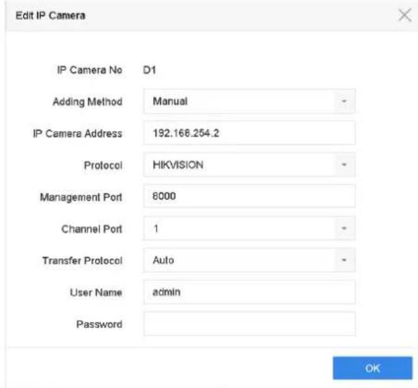
Figure 1-13 Edit Network Camera
- Select Adding Method as Manual.
Plug-and-Play
The camera is physically connected to the PoE interface. Its parameters cannot be edited.
You can go to System → Network → TCP/IP to change IP address of PoE port.
Manual
Add IP camera without physical connection via network.
- Enter IP address, User Name, and Password.
- Click OK.
1.4.4 Configure Customized Protocol
To connect network cameras which are not configured with the standard protocols, you can configure the customized protocols for them. The system provides 16 customized protocols.
Steps
- Go to More Settings → Protocol.
![Protocol Management Custom Protocol Custom Protocol 1 Protocol Name Custom 1 Stream Type Main Stream Sub Stream Type RTSP RTSP Transfer Protocol Auto Auto Port 554 554 Path Example: [Type]://[IP Address]:[Port]/[Path] rtsp://192.168.0.1:554/ch/main/av_stream OK Cancel](/content/2026/06/1194368/images/ab40a200858f80629950b7bc80f61c0a139b6186f67e97eff652d045ff851470.jpg)
Figure 1-14 Protocol Management
- Set protocol parameters.
Type
The network camera adopting custom protocol must support getting stream through standard RTSP.
Path
Contact the manufacturer of network camera for the URL (Uniform Resource Locator) of getting main stream and sub-stream.

Note
The protocol type and the transfer protocol must be supported by the network camera to add.
- Click OK.
After adding the customized protocol, you can see it in Protocol.
1.5 Platform Access
1.5.1 Configure ISUP
SDK is based on Intelligent Security Uplink Protocol (ISUP). It provides APIs, library files, and commands for the third-party platform to access devices such as NVRs, speed domes, DVRs, network cameras, mobile NVRs, mobile devices, decoding devices, etc. With this protocol, the third-party platform can realize functions like live view, playback, two-way audio, PTZ control, etc.
Steps
- Go to System → Network → Advanced → Platform Access.
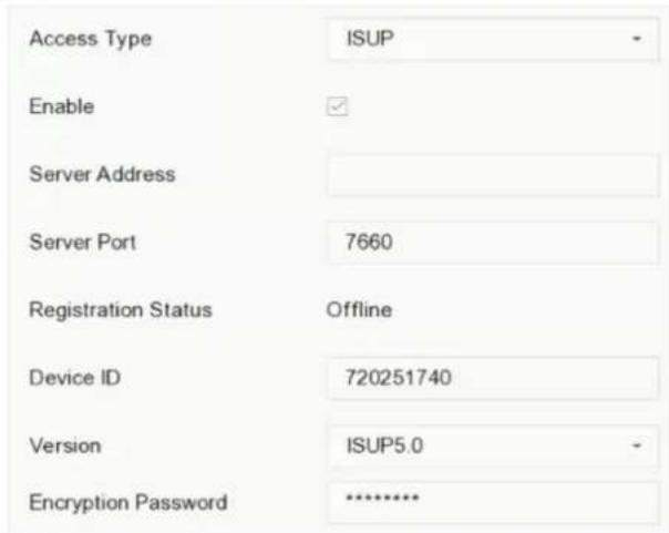
Figure 1-15 ISUP Settings
-
Select Access Type as ISUP.
-
Check Enable.

Note
Enabling ISUP will disable other platform access.
- Set the related parameters.
Server Address
The platform server IP address.
Server Port
The platform server port, ranges from 1024 to 65535. The actual port shall be provided by the platform.
Device ID
Device ID shall be provided by the platform.
Version
ISUP protocol version, only V5.0 is available.
Encryption Password
Encryption password is required when using ISUP V5.0 version, it provides more secure communication between the device and platform. Enter it for verification after the device is registered to the ISUP platform. It cannot be empty, or "ABCDEF".
- Click Apply to save the settings and restart the device.
What to do next
You can see the registration status (online or offline) after the device is restarted.
1.5.2 Configure Guarding Vision
Guarding Vision enables the mobile phone application and the service platform page (dev.guardingvision.com) to access and manage your connected NVR, providing a convenient remote access to the surveillance system.
Steps
-
Go to System → Network → Advanced → Platform Access.
-
Check Enable to activate the function. Then the service terms will pop up.
1) Enter Verification Code.
2) Scan the QR code to read the service terms and privacy statement.
3) Check The Guarding Vision service will require internet access. Please read Service Terms and Privacy Statement before enabling the service if you agree with the service terms and privacy statement.
4) Click OK.
i Note
- Guarding Vision is disabled by default.
- The verification code is empty by default. It must contain 6 to 12 letters or numbers, and it is case sensitive.
-
Check Time Sync, the device will sync time with Hik-Connect instead of NTP server.
-
Optional: Configure following parameters.
-
Check Custom and enter Server Address as your desire.
-
Check Enable Stream Encryption, then verification code is required for remote access and live view.
-
Bind your device with a Guarding Vision account.
1) Use a smart phone to scan the QR code on the device to download Guarding Vision.
2) Use Guarding Vision to scan the device QR, and bind the device.
i Note
If the device is already bound with an account, you can click Unbind to unbind with the current account.
5. Click Apply.
What to do next
You can access and manage your video recorder through Guarding Vision app or .
Chapter 2 Camera Settings
2.1 Configure Image Parameters
You can customize image parameters, including day/night switch, backlight, contrast, and saturation in Camera → Display.
Image Settings
Customize the image parameters including brightness, contrast, and saturation.
Exposure
Set the camera exposure time (1/10000 to 1 sec). A larger exposure value results in a brighter image.
Day/Night Switch
Set the camera to day, night, or auto switch mode according to time or the surrounding illumination condition. When the light diminishes at night, the camera can switches to night mode with high quality black and white image.
Backlight
Set the camera's wide dynamic range (0 to 100). When the surrounding illumination and the object have large differences in brightness, you can set the WDR value to balance the brightness level of the whole image.
Image Enhancement
For optimized image contrast enhancement that reduces noise in video stream.
2.2 Configure OSD Settings
You can configure the OSD (On-screen Display) settings for the camera, including date/time, camera name, etc.
Steps
- Go to Camera → Display.
- Select a camera as your desire.
- Edit name in Camera Name.
- Check Display Name, Display Date and Display Week to show the information on the image.
- Set the date format, time format, and display mode.
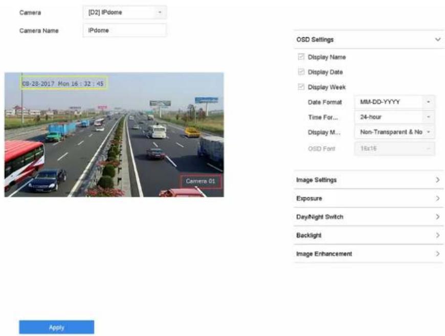
Figure 2-1 OSD Configuration Interface
- Drag the text frame on the preview window to adjust the OSD position.
- Click Apply.
2.3 Configure Privacy Mask
The privacy mask protects personal privacy by concealing parts of the image from kive view or recording with a masked area.
Steps
- Go to Camera → Privacy Mask.
- Select a camera to set privacy mask.
- Check Enable.
- Draw a zone on the window. The zone will be marked by different frame colors.
![Camera [D6] Camera 01 08-23-2017 Wed 11:52:49 Clear All Apply Enable Clear Area 1 Clear Area 2 Clear Area 3 Clear Area 4](/content/2026/06/1194368/images/bc97792bf846e980f8bcc1e6ebdecafdb612d79f4be84c339d49f06e07b16c38.jpg)
Figure 2-2 Privacy Mask Settings Interface

Note
- Up to 4 privacy masks zones can be configured and the size of each area can be adjusted.
- You can clear the configured privacy mask zones on the window by clicking the corresponding clear zone 1 to 4 icons on the right of the window, or click Clear All to clear all zones.
5. Click Apply.
2.4 Import/Export IP Camera Configuration Files
The IP camera information, including the IP address, manage port, password of admin, etc., can be saved in Microsoft Excel format and backed up to the local device. The exported file can be edited on a PC, including adding or deleting the content, and copying the setting to other devices by importing the Excel file to it.
Before You Start
When importing the configuration file, connect the storage device that contains the configuration file to the device.
Steps
-
Go to Camera → IP Camera Import/Export.
-
Click IP Camera Import/Export, and the detected external device contents appear.
-
Export or import the IP camera configuration files.
-
Click Export to export the configuration files to the selected local backup device.
- To import a configuration file, select the file from the selected backup device and click Import.

Note
After the importing process is completed, you must reboot the device to activate the settings.
2.5 Upgrade IP Cameras
The IP camera can be remotely upgraded through the device.
Before You Start
Ensure you have inserted the USB flash drive to the device, and it contains the IP camera upgrade firmware.
Steps
- On the camera management interface, select a camera.
- Go to More Settings → Upgrade.
- Select the firmware upgrade file from the USB flash drive.
- Click Upgrade.
The IP camera will reboot automatically after the upgrading completes.
Chapter 3 Live View
Live view displays the video image getting from each camera in real time.
3.1 Start Live View
Click on the main menu bar to enter the Live View.
- Select a window and double click a camera from the list to play the video from the camera in the selected window.
- Use the toolbar at the playing window bottom to realize the capture, instant playback, audio on/off, digital zoom, live view strategy, show information and start/stop recording, etc.
3.1.1 Configure Live View Settings
Live View settings can be customized. You can configure the output interface, dwell time for screen to be shown, mute or turning on the audio, the screen number for each channel, etc.
Steps
- Go to System → Live View → General.
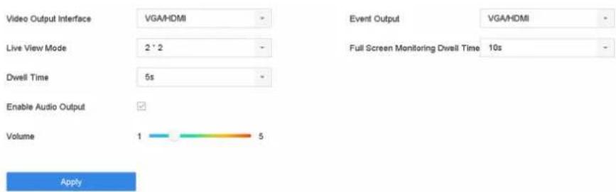
Figure 3-1 Live View-General
- Configure the live view parameters.
Video Output Interface
Select the video output to configure.
Live View Mode
Select the display mode for Live View, e.g., 2*2, 1*5, etc.
Dwell Time
The time in seconds to wait between switching of cameras when using auto-switch in Live View.
Enable Audio Output
Enable/disable audio output for the selected video output.
Volume
Adjust the Live View volume, playback and two-way audio for the selected output interface.
Event Output
Select the output to show event video.
Full Screen Monitoring Dwell Time
Set the time in seconds to show alarm event screen.
3. Click OK.
3.1.2 Configure Live View Layout
Live view displays the video image getting from each camera in real time.
Configure Custom Live View Layout
Steps
- Go to System → Live View → View.
- Click Set Custom Layout.
- Click + on the Custom Layout Configuration interface.
- Edit the layout name.
- Select a window division mode from the toolbar.
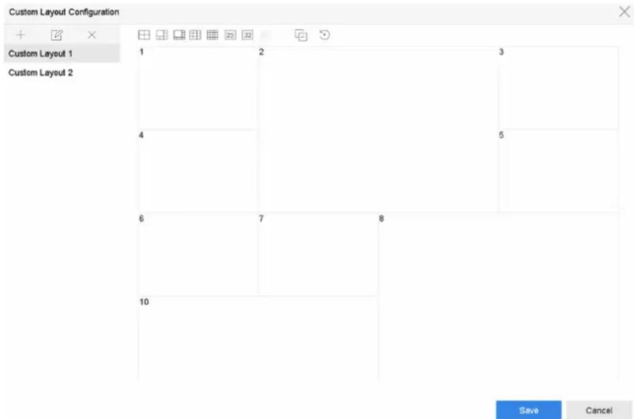
Figure 3-2 Configure Live View Layout
- Select multiple windows and click ☐ to joint the windows. The selected windows must be in rectangle area.
- Click Save.
The successfully configured layout is displayed in the list.
- Optional: Select a live view layout from the list and click ☑ to edit the name, or click ✗ to delete the name.
Configure Live View Mode
Steps
-
Go to System → Live View → View.
-
Select the video output interface.
-
Select a layout or custom layout from the toolbar.
-
Select a division window, and double-click on a camera in the list to link the camera to the window.
i Note
- You can also click-and-drag the camera to the desired window on the Live View interface to set the camera order.
-
You can enter the number in the text field to quickly search the camera from the list.
-
Click Apply.
-
Optional: Click ☐ to start live view for all channels, or click ☐ to stop all live view channels.
3.2 Configure Auto-Switch of Cameras
You can set the auto-switch of cameras to play in different display modes.
Steps
-
Go to System → Live View → General
-
Set Video Output Interface, Live View Mode, and Dwell Time.
Video Output Interface
Select the video output interface.
Live View Mode
Select the display mode for live view, e.g., 2*2, 1*5, etc.
Dwell Time
The time in seconds to dwell between switching of cameras when enabling auto-switch. The range is from 5s to 300s.
-
Go to View Settings to set the view layout.
-
Click OK to save the settings.
3.3 Configure Live View Layout
Live view displays the video image getting from each camera in real time.
3.3.1 Configure Custom Live View Layout
Steps
- Go to System → Live View → View.
- Click Set Custom Layout.
- Click + on the Custom Layout Configuration interface.
- Edit the layout name.
- Select a window division mode from the toolbar.
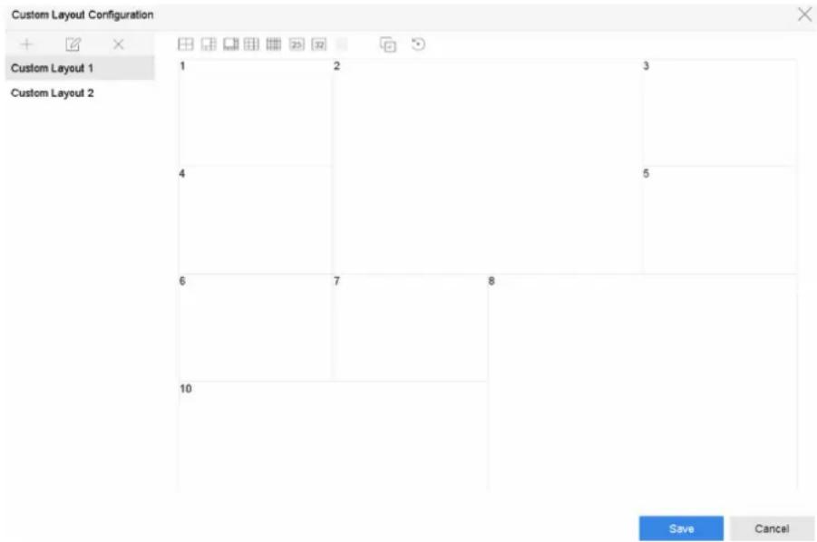
Figure 3-3 Configure Live View Layout
- Select multiple windows and click ☐ to joint the windows. The selected windows must be in rectangle area.
- Click Save.
The successfully configured layout is displayed in the list.
- Optional: Select a live view layout from the list and click ☑ to edit the name, or click ✗ to delete the name.
3.3.2 Configure Live View Mode
Steps
- Go to System → Live View → View.
-
Select the video output interface.
-
Select a layout or custom layout from the toolbar.
- Select a division window, and double-click on a camera in the list to link the camera to the window.

- You can also click-and-drag the camera to the desired window on the Live View interface to set the camera order.
-
You can enter the number in the text field to quickly search the camera from the list.
-
Click Apply.
- Optional: Click ☐ to start live view for all channels, or click ☐ to stop all live view channels.
3.4 Configure Channel-Zero Encoding
Enable the channel-zero encoding when you need to get a remote view of many channels in real time from a web browser or CMS (Client Management System) software, in order to decrease the bandwidth requirement without affecting the image quality.
Steps
- Go to System → Live View → Channel-Zero.
- Check Enable Channel-Zero Encoding.
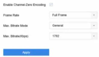
Figure 3-4 Channel-Zero Encoding
- Configure Frame Rate, Max. Bitrate Mode, and Max. Bitrate. A higher frame rate and bitrate require higher bandwidth.
- Click Apply.
You can view all the channels on one screen via CMS or web browser.
3.5 Main and Auxiliary Ports Strategy
There are five video output types: HDMI, VGA, LCD, HDMI2, and CVBS. Priority of video outputs: HDMI > VGA/LCD > HDMI2.
You can go to System → General toconfigure HDMI/VGA/LCD simultaneous output and menu output mode.
For iDS-9600NXI-I8/4F(B) series, HDMI1 and VGA are simultaneous output, HDMI1, VGA, HDMI2, CVBS cannot provide video output at the same time. When HDMI1, HDMI2, VGA, and CVBS are all
connected, CVBS does not provide video output, the main port is HDMI2, and the aux port is HDMI1 and VGA. You can enable CVBS in System → General, it requires to switch menu output mode to HTML2, and disable HDMI1/VGA.
For other series, the following table shows the main and auxiliary ports strategy when video cables for HDMI, HDMI2, and VGA are connected.
Main port
All operations are available for main port.
Aux port
You can switch to aux port to do some basic operations, like playback, switching live view image.
Third port
You can only preview camera image in third port.
Table 3-1 Main and Auxiliary Ports Strategy
| HDMI/VGA/LCD simultaneous output | Menu output mode | HDMI HDMI2 | VGA/LCD | |
| On Auto Main port | Aux port Main port | |||
| OffAuto Main port | Aux port Third port | |||
| On HDMI2 Aux port | Main port Aux port | |||
| OffHDMI2 Aux port | Main port Third port | |||
| On HDMI/VGA/LCD | Main port Aux port | Main port | ||
| OffVGA/LCD Aux port | Third port Main port | |||
| HDMI Main port Third port Aux port |
3.6 Digital Zoom
Digital Zoom zooms into the live image in different magnifications (1x to 16x).
Steps
- Start live view, click from the toolbar.
- Move the sliding bar or scroll the mouse wheel to zoom in/out the image to different magnifications (1x to 16x).

natural_image
Highway traffic scene with multiple vehicles including a red double-decker bus, cars, and cargo containers, bordered by residential buildings (no visible signage or text)Figure 3-5 Digital Zoom
3.7 Fisheye View
The device supports the fisheye camera expansion in Live View or playback mode.
Before You Start
- The fisheye expansion view feature is supported only by the
- The connected camera must support the fisheye view.
Steps
- Start live view, click ✗ to enter the fisheye expansion mode.
- Select the expansion view mode.
| 180° Panorama ( ☉) | Switch the Live View image to the 180° panorama view. | 360° Panorama ( ☉) | Switch the Live View image to the 360° panorama view. |
| PTZ Expansion ( ☉) | The PTZ Expansion is the close-up view of some defined area in the fisheye view or panoramaexpansion. It supports the electronic PTZ function, also called e-PTZ. | Radial Expansion ( ☉) | In radial expansion mode, the whole wide-angle view of the fisheye camera is displayed. This view mode iscalled Fisheye View because it approximates the vision of a fish's convex eye. The lens produces curvilinear images of a large area, while distorting the perspective and angles of objects in the image. |
3.8 3D Positioning
3D Positioning zooms in/out a specific live image area.
Steps
-
Start live view, and click
-
Zoom in/out the image.
-
Zoom in: Click on the desired position in the video image and drag a rectangle area in the lower right direction to zoom in.
- Zoom out: Drag a rectangle area in the upper left direction to move the position to the center and enable the rectangle area to zoom out.
3.9 Live View Strategy
Steps
- In the live view mode, click ✦ to enter the digital zoom operation interface in full screen mode.
- Select the live view strategy to Real-time, Balanced or Fluency.
3.10 Facial Recognition
You can enter facial recognition interface to view real-time facial recognition and stranger recognition results.
Before You Start
Ensure you have configured facial detection and face picture comparison function, refer to Face Picture Comparison for details.
Steps
- Go to live view interface, and click 🙏 in toolbar.
- Click □, □or to set window division.
- Select a window as you desired.
- Double click a camera from the camera list on the left bottom.
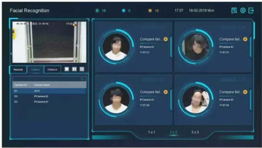
Figure 3-6 Facial Recognition
-
Click Records to view the real-time facial recognition records of selected camera. The records will also be shown in the window on the right. You can view the facial detection number at the top, including the total number, succeeded number and failed number.
-
Optional: For the unregistered face picture, you can double click it in records list, and add it to face picture library.

Note
For guest and operator user, it requires Local Parameters Settings permission to add unregistered face picture to face picture library.
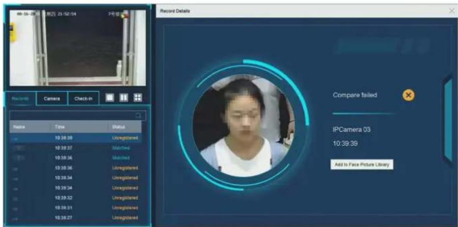
Figure 3-7 Add Unregistered Face Picture
- Optional: Click Check-in to view face picture library check-in record, including Total No., Checked In and Unchecked In.
- Optional: Click 📋 on the upper right corner to configure the display settings as you desired.
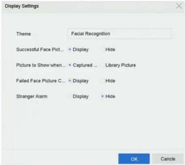
Figure 3-8 Facial Recognition Display Settings
- Optional: Click 📄 on the upper right corner to search and export record.
1) Set the search parameters as you desired.
2) Click Search.
3) Click Export Attendance Record or Export Check-in Record.
i Note
- Ensure you have inserted USB flash drive before export.
- You can click a record to review the attendance information of this individual in calendar.
- For guest and operator user, it requires "Local Video Export permission" (in "Camera Permission") to search and export record.
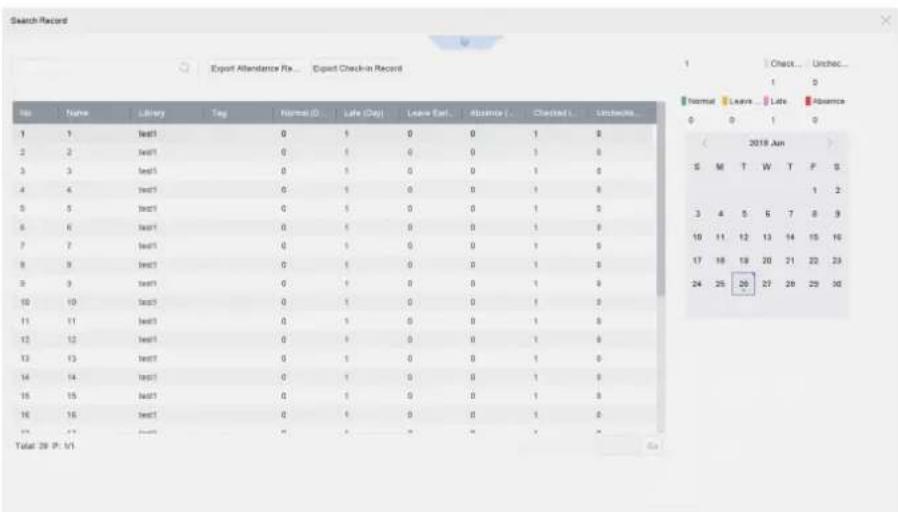
Figure 3-9 Face Recognition Search Record
3.11 PTZ Control
3.11.1 Configure PTZ Parameters
Follow these procedures to set the PTZ parameters. The PTZ parameters configuration must be done before you can control the PTZ camera.
Steps
-
Click ☐ on the quick settings toolbar of the PTZ camera's Live View.
-
Click PTZ Parameters Settings to set the PTZ parameters.
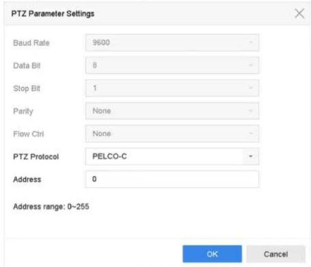
Figure 3-10 PTZ Parameters Settings
- Edit the PTZ parameters.

Note
All the parameters should be exactly match the PTZ camera parameters.
- Click OK to save the settings.
3.11.2 Set a Preset
Presets record the PTZ position and the status of zoom, focus, iris, etc. You can call a preset to quickly move the camera to the predefined position.
Steps
- Click on the quick settings toolbar of the PTZ camera's live view.
- Click directional buttons to wheel the camera to a location.
- Adjust the zoom, focus and iris status.
- Click in the lower right corner of Live View to set the preset.
| 1 | - | Preset 1 | Call | Apply | Cancel |
Figure 3-11 Set Preset
- Select the preset No. (1 to 255) from the drop-down list.
- Enter the preset name.
- Click Apply to save the preset.
- Optional: Click Cancel cancel the location information of the preset.
- Optional: Click in the lower right corner of Live View to view the configured presets.
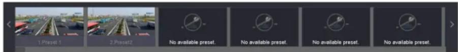
Figure 3-12 View the Configured Presets
3.11.3 Call a Preset
A preset enables the camera to point to a specified position such as a window when an event takes place.
Steps
- Click 📊 on the quick settings toolbar of the PTZ camera's Live View.
- Click in the lower right corner of Live View to set the preset.
- Select the preset No. from the drop-down list.
- Click Call to call it, or click ≈ in the lower right corner of Live View, and click the configured preset to call it.
| 1 | ✓ | Preset 1 | Call | Apply | Cancel |
Figure 3-13 Call Preset (1)
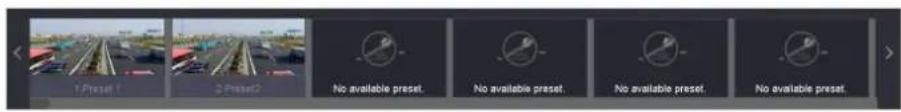
Figure 3-14 Call Preset (2)
3.11.4 Set a Patrol
Patrols can be set to move the PTZ to key points and have it stay there for a set duration before moving on to the next key point. The key points are correspond to the presets.
Steps
- Click ☐ on the quick settings toolbar of the PTZ camera's live view.
- Click Patrol to configure patrol.
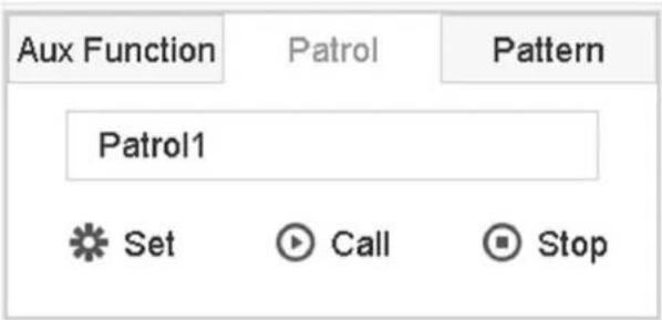
Figure 3-15 Patrol Configuration
- Select the patrol No.
- Click Set.
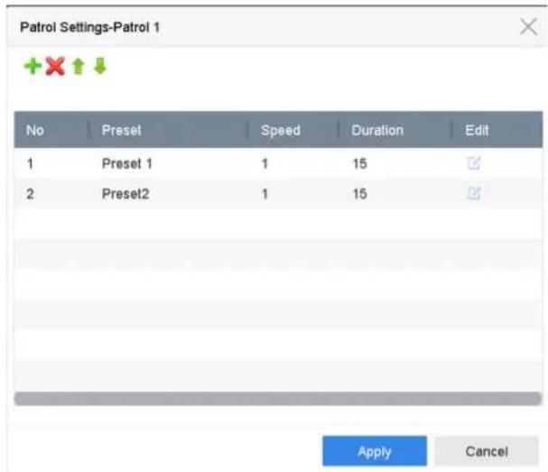
Figure 3-16 Patrol Settings
- Click to add a key point to the patrol.
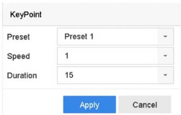
Figure 3-17 Key Point Configuration
1) Configure key point parameters.
Preset
Determines the order the PTZ will follow while cycling through the patrol.
Speed
Defines the speed the PTZ will move from one key point to the next.
Duration
Refers to the duration to stay at the corresponding key point.
2) Click Apply to save the key points to the patrol.
- Other Operation is as follows.
| Operation | DescriptionOperationDescription | |
| [08/13] | Select a key point to delete. |  Edit the added key point. Edit the added key point. |
| [1X/8C] | Adjust the key point order | [1*4] Adjust the key point order |
- Click Apply to save the patrol settings.
3.11.5 Call a Patrol
Calling a patrol makes the PTZ move according to the predefined patrol path.
Steps
- Click 📂 on the quick settings toolbar of the PTZ camera's live view.
- Click Patrol on the PTZ control panel.

Figure 3-18 Patrol Configuration
- Select a patrol.
- Click Call to start the patrol.
- Optional: Click Stop to stop the patrol.
3.11.6 Set a Pattern
Patterns can be set by recording the movement of the PTZ. You can call the pattern to make the PTZ move according to the predefined path.
Steps
- Click ⚙ on the quick settings toolbar of the PTZ camera's live view.
- Click Pattern to configure a pattern.
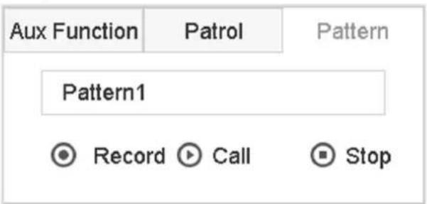
Figure 3-19 Pattern Configuration
- Select the pattern No.
- Set the pattern.
1) Click Record to start recording.
2) Click corresponding buttons on the control panel to move the PTZ camera.
3) Click Stop to stop recording. The PTZ movement is recorded as the pattern.
3.11.7 Call a Pattern
Follow the procedure to move the PTZ camera according to the predefined patterns.
Steps
- Click ♀ on the quick settings toolbar of the PTZ camera's live view.
- Click Pattern to configure pattern.
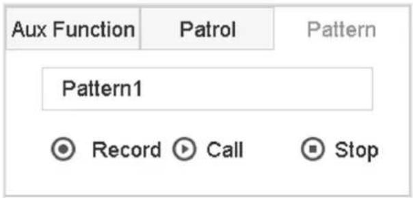
Figure 3-20 Pattern Configuration
- Select a pattern.
- Click Call to start the pattern.
- Optional: Click Stop to stop the pattern.
3.11.8 Set Linear Scan Limit
Linear Scan trigger a scan in the horizontal direction in the predefined range.
Before You Start
Make sure the connected IP camera supports the PTZ function and is properly connected.
i Note
This function is supported only by some certain models.
Steps
- Click ☐ on the quick settings toolbar of the PTZ camera's live view.
- Click directional buttons to wheel the camera to a location, and click Left Limit or Right Limit to link the location to the corresponding limit.
i Note
The speed dome linear scans from the left limit to the right limit, and you must set the left limit on the left side of the right limit. Also, the angle from the left limit to the right limit must be no more greater than 180^ .
3.11.9 One-Touch Park
Certain speed dome models can be configured to start a predefined park action (scan, preset, patrol and etc.) automatically after a period of inactivity (park time).
Before You Start
Before operating this function, make sure the connected camera supports linear scan and is in HIKVISION protocol.
Steps
-
Click 📋 on the quick settings toolbar of the PTZ camera's live view.
-
Click Park (Quick Patrol), Park (Patrol 1), or Park (Preset 1) to activate the park action.
Park (Quick Patrol)
The dome starts patrolling from the predefined preset 1 to preset 32 in order after the park time. Undefined presets will be skipped.
Park (Patrol 1)
The dome starts moving according to the predefined patrol 1 path after the park time.
Park (Preset 1)
The dome moves to the predefined preset 1 location after the park time.

Note
The park time can be set only via the speed dome configuration interface. The default value is 5s by default.
- Optional: Click Stop Park (Quick Patrol), Stop Park (Patrol 1), or Stop Park (Preset 1) to inactivate it.
3.11.10 Auxiliary Functions
You can operate the auxiliary functions including light, wiper, 3D positioning, and center on the PTZ control panel.
Before You Start
Make sure the connected IP camera supports the PTZ function, and is properly connected.
Steps
1.
Click on the quick settings toolbar of the PTZ camera's live view. The PTZ control panel displays on the right of the interface.
- Click Aux Function.
| Aux Function | Patrol | Pattern |
Figure 3-21 Aux Function Configuration
- Click the icons to operate the aux functions. See the table for the icon descriptions.
Table 3-2 Description of Aux Functions Icons
| Icon Description | |
 | Light on/off |
 | Wiper on/off |
 | 3D positioning |
 | Center |
Chapter 4 Recording and Playback
4.1 Recording
4.1.1 Configure Recording Parameters
Go to Camera → Video Parameters.
Main Stream
Main stream refers to the primary stream that affects data recorded to the hard disk drive and will directly determine your recording quality and image size.
Comparing with the sub-stream, the main stream can provide a higher quality video with higher resolution and frame rate.
Frame Rate (FPS - Frames Per Second)
It refers to how many frames are captured each second. A higher frame rate is advantageous when there is movement in the video stream, as it maintains image quality throughout.
Resolution
Image resolution is a measure of how much detail a digital image can hold. The greater the resolution, the greater the level of detail. Resolution can be specified as the number of pixel-columns (width) by the number of pixel-rows (height), e.g., 1024 × 768 .
Bitrate
The bit rate (in kbit/s or Mbit/s) is often referred to as speed, but actually defines the number of bits/time unit and not distance/time unit.
Enable H.264+
H.264+ combines intelligent analysis technology with predictive encoding, noise suppression, and long-term bit rate control to realize a lower bit rate, which plays asignificant role in cutting storage costs and provides a higher return value for the investment.
Enable H.265+
H.265+ is an optimized encoding technology based on the standard H.265/HEVC compression. With H.265+, the video quality is almost the same as that of H.265/HEVC but with less transmission bandwidth and storage capacity required.
i Note
- A higher resolution, frame rate and bit rate setting will provide you the better video quality, but it will also require more internet bandwidth and use more storage space on the hard disk drive.
- H.264+ or H.265+ encoding technology is only available for certain models.
Sub-Stream
Sub-stream is a second codec that runs alongside the main stream. It allows you to reduce the outgoing internet bandwidth without sacrificing your direct recording quality.
Sub-stream is often exclusively used by apps to view live video. Users with limited internet speeds may benefit most from this setting.
Picture
The picture refers to the live picture capture in continuous or event recording type. (Storage → Capture Schedule → Advanced
Picture Quality
Set the picture quality to low, medium or high. The higher picture quality results in more storage space requirement.
Interval
The interval of capturing live picture.
Capture Delay Time
The duration of capturing pictures.
Configure Advanced Recording Parameters
Steps
- Go to Storage → Schedule → Record.
- Check Enable Schedule to enable scheduled recording.
- Click Advanced to set the advanced parameters.
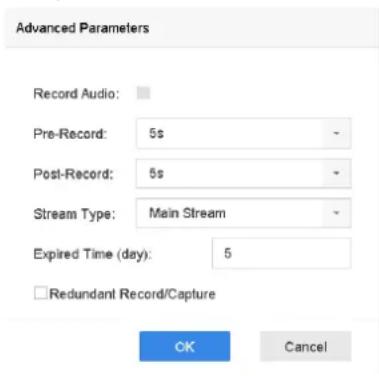
Figure 4-1 Advanced Record Settings
Record Audio
Enable or disable audio recording.
Pre-record
The time you set to record before the scheduled time or event. For example, when an alarm triggers the recording at 10:00, and if you set the pre-record time as 5 seconds, the camera records at 9:59:55.
Post-record
The time you set to record after the event or the scheduled time. For example, when an alarm triggered recording ends at 11:00, and if you set the post-record time as 5 seconds, it records till 11:00:05.
Stream Type
Main stream and sub-stream are selectable for recording. When you select sub-stream, you can record for a longer time with the same storage space.
Expired Time
The expired time is period for a recorded file to be kept in the HDD. When the deadline is reached, the file will be deleted. If you set the expired time to 0, the file will not be deleted. The actual keeping time for the file should be determined by the capacity of the HDD.
Redundant Record/Capture
By enabling redundant record or capture you save the record and captured picture in the redundant HDD.
4.1.2 Enable the H.265 Stream Access
The device can automatically switch to the H.265 stream of IP camera (which supports H.265 video format) for the initial access.
Go to Camera → More Settings → H.265 Auto Switch Configuration to enable the function.
4.1.3 ANR
ANR (Automatic Network Replenishment) function enables the IP camera to save the recording files in the local storage when the network is disconnected, and when the network is resumed, it uploads the files to the device.
Steps
- Log in your device via web browser and go to Configuration → Storage → Schedule Settings → Advanced.
- Check Enable ANR.
- Click OK.
4.1.4 Manual Recording
You can click 📄 manually start/stop recording videos at live view.
4.1.5 Configure Plan Recording
The camera would automatically start/stop recording according to the configured recording schedule.
Before You Start
- Ensure you have installed the HDDs to the device or added the network disks before storing the video files, pictures and log files.
- Before enabling Motion, Alarm, M | A (motion or alarm), M & A (motion and alarm) and Event triggered recording and capture, you must configure the motion detection settings, alarm input settings and other events as well. Refer to for details.
Steps
-
Go to Storage → Schedule → Record.
-
Select a camera.
-
Check Enable Schedule.
-
Select a recording type.
Continuous
Scheduled recording.
Event
Recording triggered by all event triggered alarm.
Motion
Recording triggered by motion detection.
Alarm
Recording triggered by alarm.
M/A
Recording triggered by either motion detection or alarm.
M&A
Recording triggered by motion detection and alarm.
- Drag the cursor on time bar to set the record schedule.
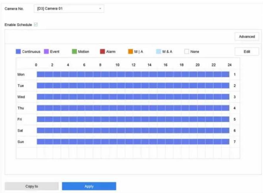
Figure 4-2 Record Schedule
i Note
- You can repeat the above steps to set schedule recording or capture for each day in the week.
-
Continuous recording is applied to each day by default.
-
Optional: Copy the recording schedule to other camera(s).
1) Click Copy to.
2) Select camera(s) to duplicate with the same schedule settings.
3) Click OK.
- Click Apply.
4.1.6 Configure Continuous Recording
The device can continuously record the video within the configured time schedule.
Steps
- Go to Camera → Encoding Parameters → Recording Parameters.
- Set the continuous main stream/sub-stream recording parameters for the camera.
- Go to Storage → Recording Schedule.
- Drag the mouse on the time bar to set the continuous recording schedule. Refer to Configure Plan Recording for details.
4.1.7 Configure Motion Detection Triggered Recording
You can configure the recording triggered by the motion detection event.
Steps
- Go to System → Event → Normal Event → Motion Detection.
- Configure the motion detection and select the channel (s) to trigger the recording when motion event occurs. Refer to Configure Linkage Actions for details.
- Go to Camera → Encoding Parameters → Recording Parameters.
- Set the event main stream/sub-stream recording parameters for the camera.
- Go to Storage → Recording Schedule.
- Select the recording type to Motion.
- Drag the mouse on the time bar to set motion detection recording schedule. Refer to Configure Plan Recording for details.
4.1.8 Configure Event Triggered Recording
You can configure the recording triggered by the motion detection, motion detection and alarm, face detection, vehicle detection, line crossing detection, etc.
Steps
- Go to System → Event.
- Configure the event detection and select the channel(s) to trigger the recording when event occurs. Refer to Event for details.
- Go to Camera → Encoding Parameters → Recording Parameters.
- Set the event main stream/sub-stream recording parameters for the camera.
- Go to Storage → Recording Schedule.
- Select the recording type to Event.
- Drag the mouse on the time bar to set the event detection recording schedule. Refer to Configure Plan Recording for details.
4.1.9 Configure Alarm Triggered Recording
You can configure the recording triggered by the motion detection, face detection, vehicle detection, line crossing detection, etc.
Steps
- Go to System → Event → Normal Event → Alarm Input.
- Configure the alarm input and select the channel(s) to trigger the recording when alarm occurs. Refer to Event for details.
- Go to Camera → Encoding Parameters → Recording Parameters.
- Set the event main stream/sub-stream recording parameters for the camera.
- Go to Storage → Recording Schedule.
-
Select the recording type to Alarm.
-
Drag the mouse on the time bar to set the alarm recording schedule. Refer to Configure Plan Recording for details.
4.1.10 Configure Picture Capture
The picture refers to the live picture capture in continuous or event recording type. Only certain models support this function.
Steps
-
Go to Camera → Encoding Parameters → Capture.
-
Set the picture parameters.
Resolution
Set the resolution of the picture to capture.
Picture Quality
Set the picture quality to low, medium or high. The higher picture quality results in more storage space requirement.
Interval
The interval of capturing live picture.
- Go to Storage → Capture Schedule.
- Select the camera to configure the picture capture.
- Set the picture capture schedule. Refer to Configure Plan Recording for details.
4.1.11 Configure Holiday Recording
You may want to have different plan for recording on holiday, this function allows you to set the recording schedule on holiday for the year.
Steps
- Go to System → Holiday.
- Select a holiday item from the list.
- Click ☑ to edit the selected holiday.
- Check Enable.
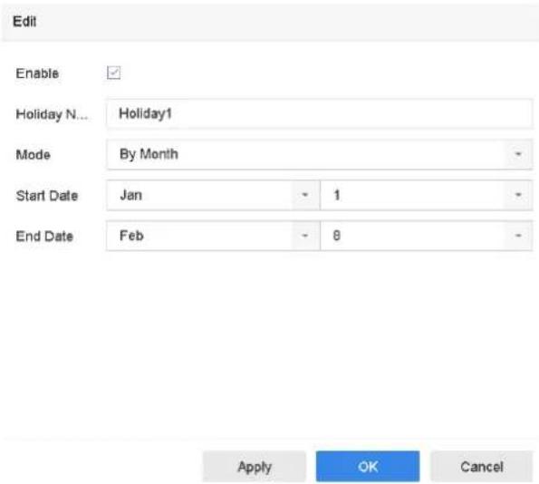
Figure 4-3 Edit Holiday Settings
- Set Holiday Name, Mode, Start Date, and End Date.
- Click OK.
- Set the schedule for holiday recording. Refer to Configure Plan Recording for details.
4.1.12 Configure Redundant Recording and Capture
Enabling redundant recording and capture, which means saving the record files and captured pictures not only in the R/W HDD but also in the redundant HDD, will effectively enhance the data safety and reliability.
Before You Start
You must set the storage mode to Group before you set the HDD property to Redundancy. For detailed information, refer to Configure HDD Group. There should be at least another HDD which is in Read/Write status.
Steps
- Go to Storage → Storage Device.
- Select a HDD from the list and click ☑ to enter the Local HDD Settings interface.
- Set the HDD property to Redundancy.
- Go to Storage → Schedule Settings → Record Schedule/Capture Schedule.
- Click Advanced to set the camera recording parameters.
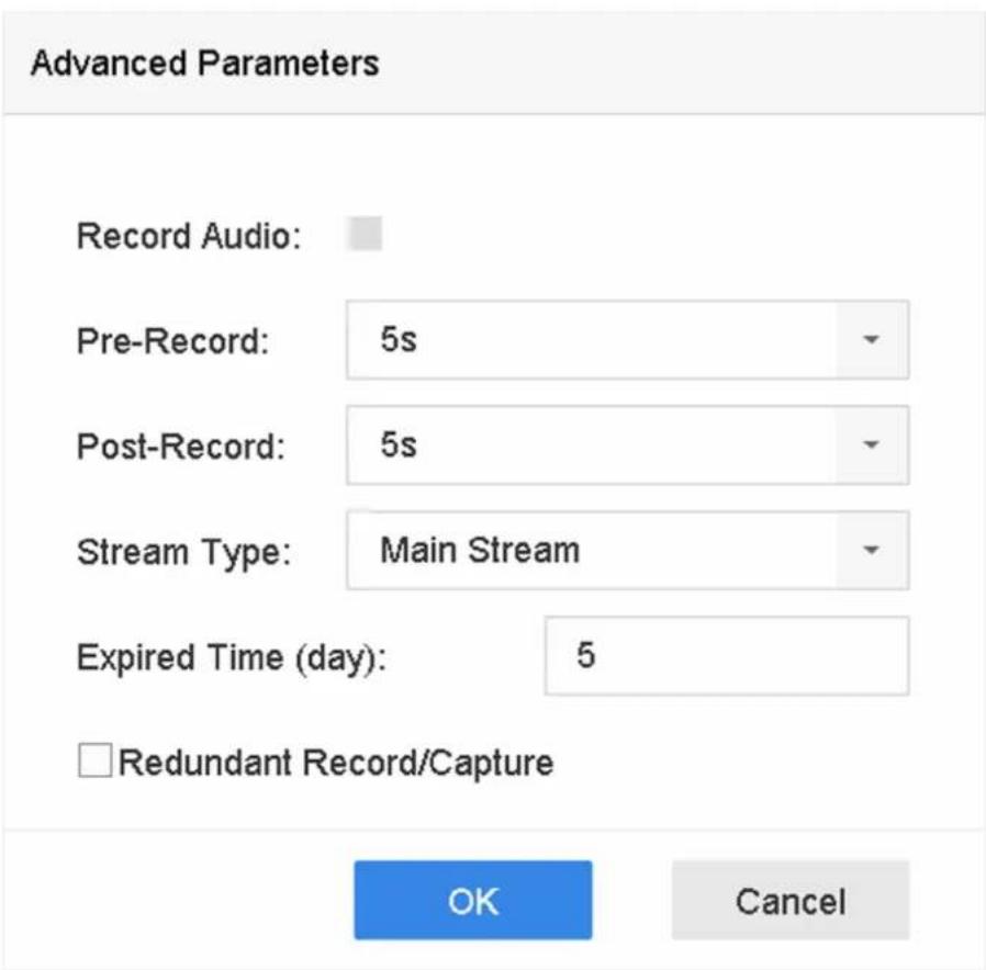
Figure 4-4 Record Parameters
- Check Redundant Record/Capture.
- Click OK to save settings.
4.2 Playback
4.2.1 Instant Playback
Instant playback enables the device to play the recorded video files recorded in the last five minutes. If no video is found, it means there is no recording during the last five minutes.
After selecting the camera on Live View, you can move the cursor to the window bottom to access the toolbar, and click to start instant playback.
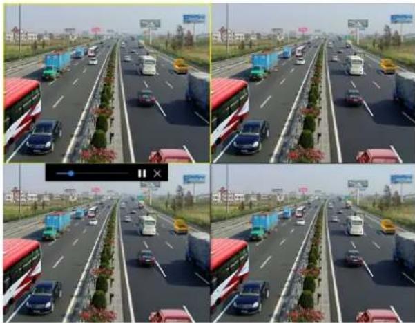
natural_image
Four-panel composite image showing a multi-lane highway with vehicles and traffic, no visible text or symbols.Figure 4-5 Playback Interface
4.2.2 Play Normal Video
Go to Playback, select date and camera(s), and use the toolbar at the bottom to perform playback operations. Refer to Playback Operations. You can click camera(s) to execute simultaneous playback of multiple camera(s).
i Note
256x playing speed is supported.
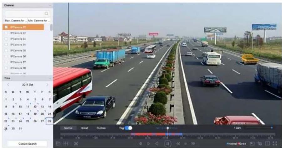
Figure 4-6 Play Normal Video Interface
4.2.3 Play Smart Searched Video
In smart playback mode, the device can analyze videos that containing motion, line, or intrusion detection information, and mark them in red.
Go to Playback, click Smart, and then click motion detection (☐), line crossing detection (☐), or intrusion detection (☐) in the toolbar at the bottom to play the video as your desire.
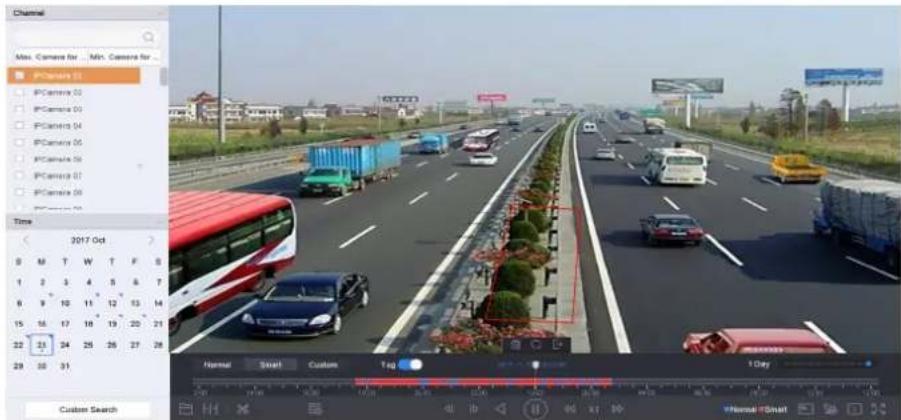
Figure 4-7 Payback by Smart Search
4.2.4 Play Custom Searched Files
You can play video by customized search conditions.
Steps
- Go to Playback.
- Select camera(s) from the list.
- Click Custom Search on the left bottom.
- Enter search conditions, including Time, File Status, Event Type, etc.
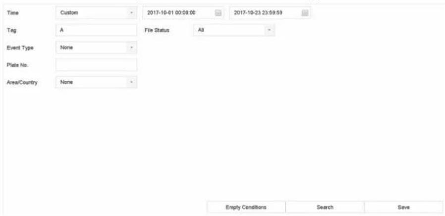
Figure 4-8 Custom Search
5. Click Search.
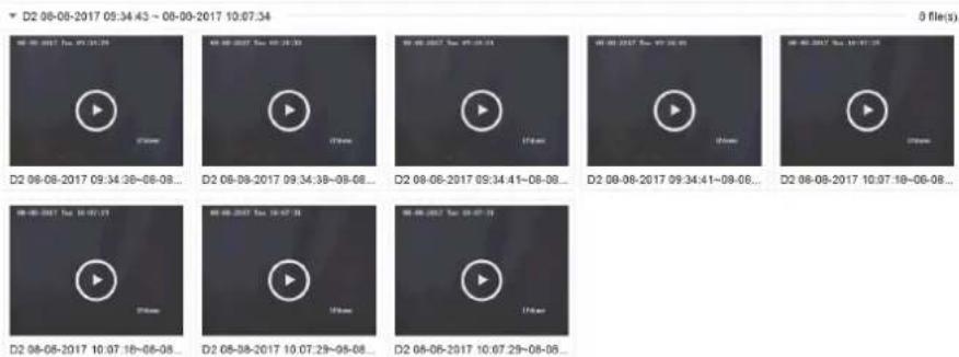
Figure 4-9 Custom Searched Video Files
- Select a file and start playing the video on search results interface.
4.2.5 Play Tag Files
Video tag allows you to record information, such as people and locations of a certain time point, during playback. You can use video tag(s) to search videofiles and position time point.
Add Tag Files
Steps
- Go to Playback.
- Search and play back the video file(s).
- Click to add the tag.
- Edit the tag information.
- Click OK.

Max. 64 tags can be added to a single video file.
Play Tag Files
Steps
- Go to Playback.
- Click Custom Search at the left bottom.
- Enter search conditions, including time and tag keyword.
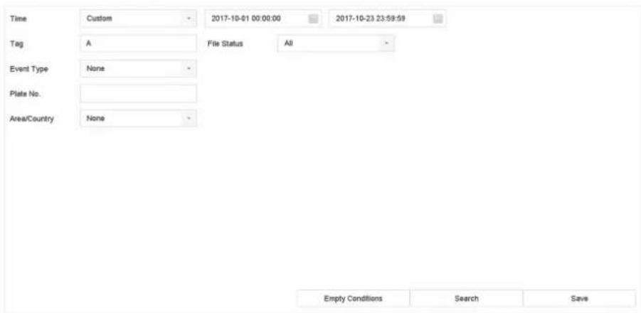
Figure 4-10 Tag Search
4. Click Search.
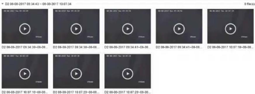
Figure 4-11 Searched Tag Files
- Select a tag file, and play the video on the search results interface.
4.2.6 Play by Sub-periods
The video files can be played in multiple sub-periods simultaneously on the screen.
Steps
- Go to Playback.
- Click at the lower-left corner.
- Select a camera.
- Set the start time and end time for searching video.
- Select the different multi-period at the lower-right corner, e.g., 4-Period.

Note
According to the defined number of split-screens, the video files on the selected date can be divided into average segments for playback. E.g., if there are video files existing between 16:00 and 22:00, and the 6-screen display mode is selected, then it can play the video files for 1 hour on each screen simultaneously.
4.2.7 Play Log Files
Play back record file(s) associated with channels after searching system logs.
Steps
- Go to Maintenance → Log Information.
- Click Log Search.
- Set search time and type and click Search.
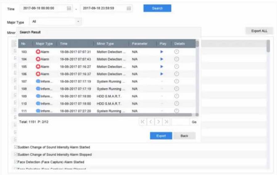
Figure 4-12 System Log Search Interface
- Choose a log with a video file and click to start playing the log file.
4.2.8 Play External Files
You can play files from external storage devices.
Before You Start
Connect the storage device with the video files to your device.
Steps
- Go to Playback.
- Click at the lower-left corner.
- Click ▶, or double-click the file to play it.
4.3 Playback Operations
4.3.1 Normal/Important/Custom Video
During the playback, you can select the following three modes to play the video.
Normal
Video files from the continuous recording.
Important
Video files from the event and alarm recording triggered recording.
Custom
Video files searched by custom conditions.
4.3.2 Set Play Strategy in Important/Custom Mode
When you are in the smart or custom video playback mode, you can set the playing speed separately for the normal video and the smart/custom video, or you can select to skip the normal video.
In the Smart/Custom video playback mode, click 📄 to set the play strategy.
- When Do not Play Normal Videos is checked, the device will skip the normal video and play the smart (motion/line crossing/intrusion) video and the custom (searched video) only in the normal speed (X1).
- When Do not Play Normal Videos is unchecked, you can set the play speed for the normal video the smart/custom video separately. The speed range is from X1 to XMAX.

Note
You can set the speed in the single-channel play mode only.
4.3.3 Edit Video Clips
You can cut and export video clips during playback.
Steps
- Go to Playback
- Click at the bottom toolbar.
- Set the start time and end time. You can click [✗] to set the time period, or set a time segment on time bar.
- Click ☐ to save the video clip to a storage device.
4.3.4 Switch between Main Stream and Sub-Stream
You can switch between the main stream and the sub-stream during the playback.
| Icon Description | |
| Play the video in main stream. | |
| Play the video in sub-stream. |
i Note
The encoding parameters for the main stream and sub-stream can be configured in Storage → Encoding Parameters.
4.3.5 Thumbnails View
With the thumbnails view on the playback interface, you can conveniently locate the required video files on the time bar.
In the playback mode, position the cursor on time bar to get preview thumbnails.
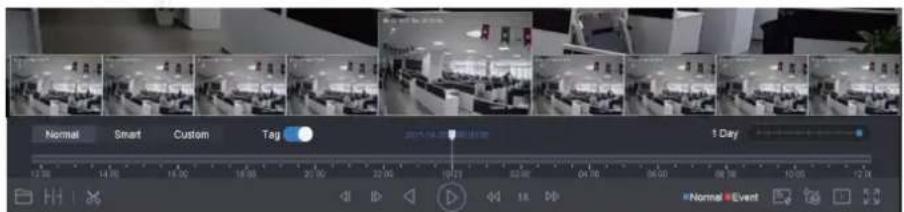
Figure 4-13 Thumbnails View
You can click a thumbnail to enter the full-screen playback.
4.3.6 Fisheye View
The device supports the fisheye camera expansion in Live View or playback mode.
Before You Start
- The fisheye expansion view feature is supported only by the
- The connected camera must support the fisheye view.
Steps
- Start live view, click 🔒 to enter the fisheye expansion mode.
- Select the expansion view mode.
| 180° Panorama ( ) | Switch the Live View image to the 180° panorama view. | 360° Panorama ( ) | Switch the Live View image to the 360° panorama view. |
| PTZ Expansion ( ) | The PTZ Expansion is the close-up view of some defined area in the fisheye view or panorama expansion. It supports the electronic PTZ function, also called e-PTZ. | Radial Expansion ( ) | In radial expansion mode, the whole wide-angle view of the fisheye camera is displayed. This view mode is called Fisheye View because it approximates the vision of a fish's convex eye. The lens produces curvilinear images of a large area, while distorting the perspective and angles of objects in the image. |
4.3.7 Fast View
Hold the mouse to drag on the time bar to get a fast view of the video files.
In the Video Playback mode, hold and drag the mouse through the playing time bar to fast view the video files.
Release the mouse at the required time point to enter the full-screen playback.
4.3.8 Digital Zoom
Digital Zoom zooms into the live image in different magnifications (1x to 16x).
Steps
-
Start live view, click from the toolbar.
-
Move the sliding bar or scroll the mouse wheel to zoom in/out the image to different magnifications (1x to 16x).

natural_image
Highway traffic scene with multiple lanes, vehicles, and a red double-decker bus, no visible text or signageFigure 4-14 Digital Zoom
Chapter 5 Event
5.1 Normal Event Alarm
5.1.1 Configure Motion Detection Alarms
Motion detection enables the device to detect the moving objects in the monitored area and trigger alarms.
Steps
- Go to System → Event → Normal Event → Motion Detection.
- Select a camera.
- Check Enable.
- Set the motion detection rule.
For cameras have human and vehicle detection function.
Click Draw Area to draw the detection area(s) on the preview screen.
Set Target Detection as Human Body or Vehicle to discard alarms which are not triggered by human body or vehicle.
For cameras do not have human and vehicle detection function.
Click Full screen to set the full-screen as the detection area, or drag on the preview screen to draw the customized detection area.
- Set Sensitivity (0-100). The sensitivity allows you to calibrate how readily movement triggers the alarm. A higher value results in the more readily to triggers motion detection.
- Set the arming schedule. Refer to Configure Arming Schedule.
- Set linkage actions. Refer to Configure Linkage Actions.
5.1.2 Configure Video Loss Alarms
Video loss detection detects video loss of a channel and takes alarm response action(s).
Steps
- Go to System → Event → Normal Event → Video Loss.
- Select a camera.
- Check Enable.
- Set the arming schedule. Refer to Configure Arming Schedule.
- Set linkage actions. Refer to Configure Linkage Actions.
5.1.3 Configure Video Tampering Alarms
Video tampering detection triggered an alarm when the camera lens is covered and takes alarm response action(s).
Steps
- Go to System → Event → Normal Event → Video Tampering.
- Select a camera.
- Check Enable.
- Set the video tampering area. Drag on the preview screen to draw the customized video tampering area.
- Set Sensitivity (0-2). 3 levels are available. The sensitivity calibrates how readily movement triggers the alarm. A higher value more readily triggers the video tampering detection.
- Set the arming schedule. Refer to Configure Arming Schedule.
- Set linkage actions. Refer to Configure Linkage Actions.
5.1.4 Configure Sensor Alarms
Set the handling action of an external sensor alarm.
Steps
- Go to System → Event → Normal Event → Alarm Input.
- Select an alarm input item from the list and click
- Select the alarm input type.
- Edit the alarm name.
- Check Input.
- Set the arming schedule. Refer to Configure Arming Schedule.
- Set linkage actions. Refer to Configure Linkage Actions.
5.1.5 Configure Exceptions Alarms
Exception events can be configured to take the event hint in the Live View window and trigger alarm output and linkage actions.
Steps
- Go to System → Event → Normal Event → Exception.
- Optional: Enable the event hint to display it in the live view window.
1) Check Enable Event Hint.
2) Click ⚙ to select the exception type(s) to take the event hint.
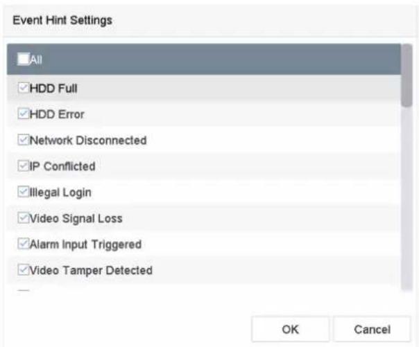
Figure 5-1 Event Hint Settings
- Select an exception type.
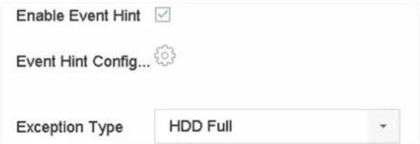
Figure 5-2 Exceptions Handling
- Set the linkage actions. Refer to Configure Linkage Actions.
5.2 VCA Event Alarm
The device supports receiving VCA detections sent by connected IP cameras. Enable and configure VCA detection on the IP camera settings interface first.

Note
• VCA detections must be supported by the connected IP camera.
• Refer to the network camera user manual for detailed VCA detection instructions.
5.2.1 Temperature Screening
After connecting with specified thermography cameras, the device can display temperature measurement results, and notify you with audio alert when normal or abnormal temperature is detected.
Before You Start
Ensure your thermography camera support this function, and it is properly configured.
Steps
- Go to System → Event → Smart Event.
- Select the optical channel of thermography camera.
- Click Face Capture.
- Optional: Check Save VCA Picture to save the captured pictures of face detection.
- Set the arming schedule. Refer to Configure Arming Schedule.
- Set linkage actions. Refer to Configure Linkage Actions. If you only requires to conduct linkage actions when the thermography camera detects abnormal temperature, go to More, and check Abnormal Body Temperature.

Note
The abnormal temperature is detected and defined by the thermography camera.
- Go to Audio Alert, and check Normal Temperature or Abnormal Temperature as your desire. It will notify you with audio alert when normal or abnormal temperature is detected by the camera.
| Arming Schedule | Linkage Action | Audio Alert | More |
| Normal Temperature | |||
| ✓ Abnormal Temperature | |||
Figure 5-3 Audio Alert
- Click Apply.
What to do next
- You can check 📁 of Target Detection in live view to view detection results.
- You can go to File Management → Smart Search → Search by Appearance to search detection results.
5.2.2 Loitering Detection
Loitering detection is used to detect whether a target stays within a specified area longer than the set time and trigger alarm for linked actions.
Steps
- Go to Smart Analysis → Smart Event Settings → Other Events.
- Select a camera.
- Click Loitering Detection.
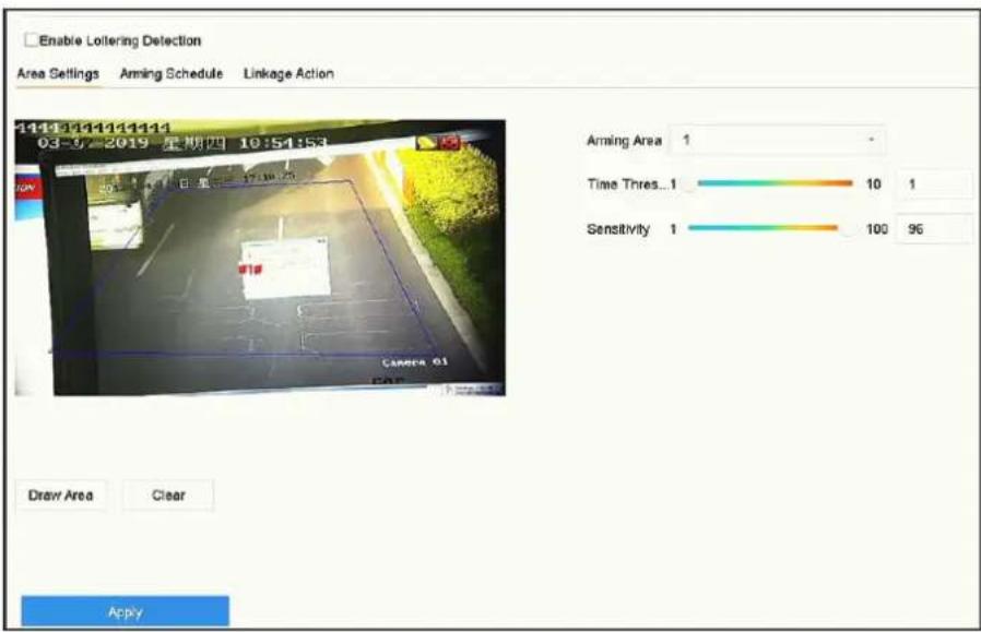
Figure 5-4 Loitering Detection
-
Check Enable Loitering Detection..
-
Optional: Check Save VCA Picture to save the captured loitering detection pictures.
-
Set loitering detection parameters.
1) Select Arming Region. Up to 4 regions are selectable.
2) Set Time Threshold.
Time Threshold
The time of car staying in the region. If the value is 10, an alarm is triggered after the car has stayed in the region for 10s. Its range is [1s-10s].
3) Set Sensitivity.
Sensitivity
Similarity of the background image to the object. The higher the value, the easier the detection alarm will be triggered.
- Set the arming schedule. Refer to Configure Arming Schedule.
- Set the linkage actions. Refer to Configure Linkage Actions.
- Click Apply.
5.2.3 People Gathering Detection
People gathering detection is used to detect whether the density of human bodies within a specified area exceeds the set value and trigger alarm for linked actions.
Steps
- Go to Smart Analysis → Smart Event Settings → Other Events.
- Select a camera.
- Click People Gathering.
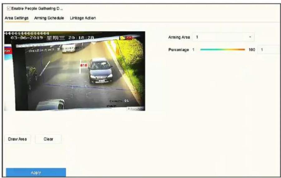
Figure 5-5 People Gathering Detection
-
Check Enable People Gathering Detection.
-
Optional: Check Save VCA Picture to save the captured people gathering detection pictures.
-
Set people gathering detection parameters.
1) Select Arming Region. Up to 4 regions are selectable.
2) Click Draw Area to draw a quadrilateral in the preview window by specifying four vertices of the area.
3) Set Percentage.
Percentage
The percentage refers to the density of human bodies within the area. If it exceeds the threshold value, the device will trigger alarm.
- Set the arming schedule. Refer to Configure Arming Schedule.
- Set the linkage actions. Refer to Configure Linkage Actions.
- Click Apply.
5.2.4 Fast Moving Detection
Fast moving detection is used to detect suspicious running and chasing, over speed and fast moving. It will trigger alarm when an object is moving fast and send notification to arming host so that necessary actions can be taken in advance.
Steps
- Go to Smart Analysis → Smart Event Settings → Other Events.
- Select a camera.
- Click Fast Moving.
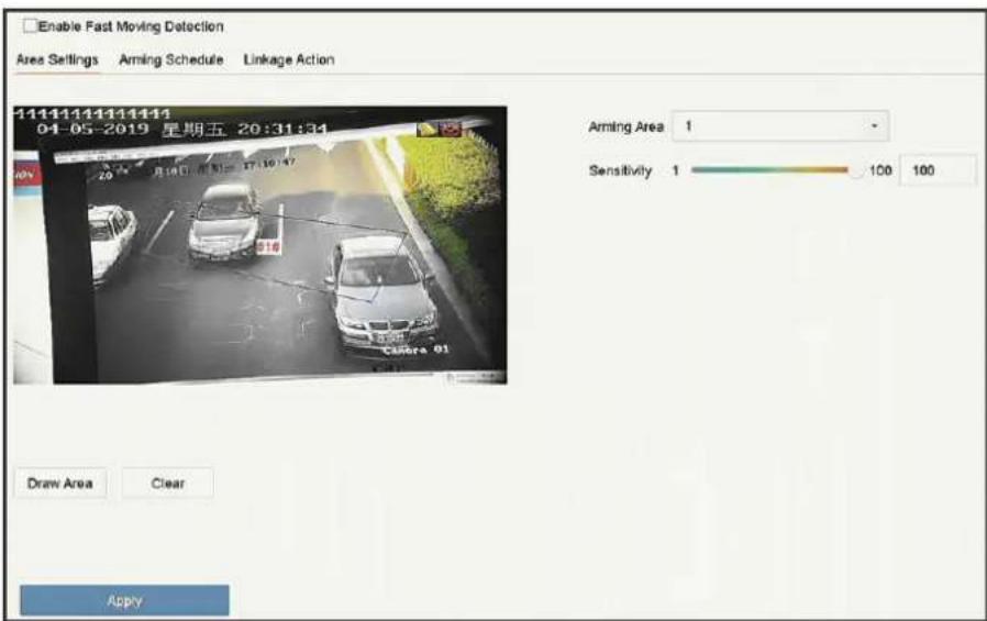
Figure 5-6 Fast moving detection
-
Check Enable Fast Moving.
-
Optional: Check Save VCA Picture to save the captured fast moving detection pictures.
-
Set fast moving detection parameters.
1) Select Arming Region. Up to 4 regions are selectable.
2) Click Draw Area to draw a quadrilateral in the preview window by specifying four vertices of the area.
3) Set Sensitivity.
Sensitivity
Similarity of the background image to the object. The higher the value, the easier the detection alarm will be triggered.
- Set the arming schedule. Refer to Configure Arming Schedule.
- Set the linkage actions. Refer to Configure Linkage Actions.
- Click Apply.
5.2.5 Parking Detection
Parking detection is used to detect parking violation in set area, applied in expressway and one-way street.
Steps
- Go to Smart Analysis → Smart Event Settings → Other Events.
- Select a camera.
- Click Parking.
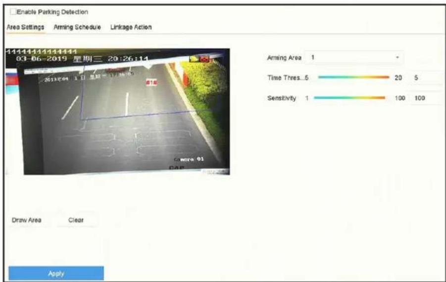
Figure 5-7 Parking Detection
-
Check Enable Parking Detection.
-
Optional: Check Save VCA Picture to save the captured parking detection pictures.
-
Set parking detection parameters.
1) Select Arming Region. Up to 4 regions are selectable.
2) Set Time Threshold.
Time Threshold
The time of car staying in the region. If the value is 10, an alarm is triggered after the car has stayed in the region for 10s. Its range is [5s-20s].
3) Set Sensitivity.
Sensitivity
Similarity of the background image to the object. The higher the value, the easier the detection alarm will be triggered.
- Set the arming schedule. Refer to Configure Arming Schedule.
- Set the linkage actions. Refer to Configure Linkage Actions.
- Click Apply.
5.2.6 Unattended Baggage Detection
Unattended baggage detection detects the objects left over in a predefined region such as the baggage, purses, dangerous materials, etc., and a series of actions can be taken when the alarm is triggered.
Steps
- Go to Smart Analysis → Smart Event Settings → Other Events.
- Select a camera.
- Click Unattended Baggage.
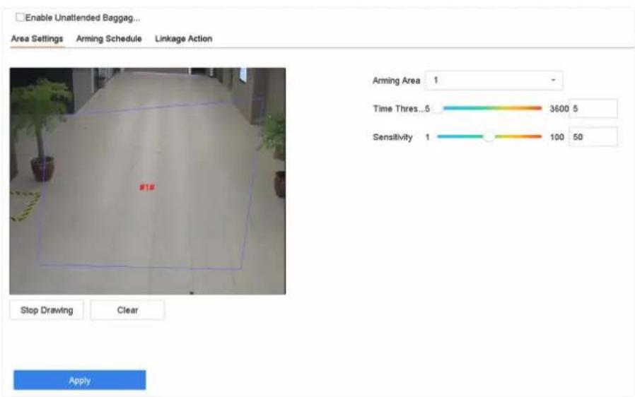
Figure 5-8 Unattended Baggage Detection
-
Check Enable Unattended Baggage Detection.
-
Optional: Check Save VCA Picture to save the captured unattended baggage detection pictures.
-
Set the detection rules and detection areas.
1) Select Arming Region. Up to 4 regions are selectable.
2) Drag the sliders to set Time Threshold and Sensitivity.
Time Threshold
The time of the objects are left in the region. If the value is 10, an alarm is triggered after the object is left and stayed in the region for 10s. Its range is [5s-20s].
Sensitivity
Similarity of the background image to the object. The higher the value, the easier the detection alarm will be triggered.
3) Click Draw Region and draw a quadrilateral in the preview window.
- Set the arming schedule. Refer to Configure Arming Schedule.
- Set linkage actions. Refer to Configure Linkage Actions.
- Click Apply.
5.2.7 Object Removal Detection
The object removal detection function detects the objects removed from a pre-defined region, such as the exhibits on display, and a series of actions can be taken when the alarm is triggered.
Steps
- Go to Smart Analysis → Smart Event Settings → Other Events.
- Select a camera.
- Click Object Removable.
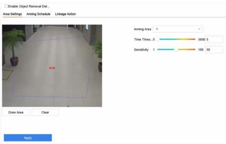
Figure 5-9 Object Removal Detection
-
Check Enable Object Removable Detection.
-
Optional: Check Save VCA Picture to save the captured object removable detection pictures.
-
Follow these steps to set the detection rules and detection areas.
1) Select Arming Region. Up to 4 regions are selectable.
2) Drag the sliders to set Time Threshold and Sensitivity.
Time Threshold
The time of the objects removed from the region. If the value is 10, alarm will be triggered after the object disappears from the region for 10s. Its range is [5s-20s].
Sensitivity
The similarity degree of the background image. If the sensitivity is high, a very small object taken from the region will trigger the alarm.
3) Click Draw Area and draw a quadrilateral in the preview window by specifying four vertices of the detection region.
- Set the arming schedule. Refer to Configure Arming Schedule.
- Set the linkage actions. Refer to Configure Linkage Actions.
- Click Apply.
5.2.8 Audio Exception Detection
Audio exception detection detects abnormal sounds in the surveillance scene, such as a sudden increase/decrease in sound intensity.
Steps
- Go to Smart Analysis → Smart Event Settings → Other Events.
- Select a camera.
- Click Audio Exception.
![Face Detection Audio Execution Vehicle Defocus Line Crossing Sudden Scene Intrusion PIR Alarm Region Entrance Region Exiting Unattended Ba... Object Removal Camera [D1] iCamera 01 Save VCA PI... Exception Detection Aming Schedule Linkage Action Audio Loss Exception Sudden Increase of Sound Intens... Sensitivity 1 100 50 Sound Int... 1 100 50 Sudden Decrease of Sound Inten... Sensitivity 1 100 50 Apply](/content/2026/06/1194368/images/32420fd2f24a2eee13577b1d78a78cd5dedd86adfc7433be9aad3ab82ca83d90.jpg)
Figure 5-10 Audio Exception Detection
-
Optional: Check Save VCA Picture to save the captured audio exception detection pictures.
-
Set the detection rules:
1) Select Exception Detection.
2) Check Audio Loss Exception, Sudden Increase of Sound Intensity Detection, and/or Sudden Decrease of Sound Intensity Detection.
Audio Loss Exception
Detects a steep sound rise in the surveillance scene. You can set the detection sensitivity and threshold for steep sound rise by configuring its Sensitivity and Sound Intensity Threshold
Sensitivity
The smaller the value, the more severe the change must be to trigger the detection. Range [1-100].
Sound Intensity Threshold
It can filter the sound in the environment. The louder the environment sound, the higher the value should be. Adjust it according to the environment. Range [1-100].
Sudden Decrease of Sound Intensity Detection
Detects a steep sound drop in the surveillance scene. You need set the detection sensitivity [1-100].
- Set the arming schedule. Refer to Configure Arming Schedule.
- Set the linkage actions. Refer to Configure Linkage Actions.
- Click Apply.
5.2.9 Defocus Detection
Image blur caused by lens defocus can be detected.
Steps
- Go to Smart Analysis → Smart Event Settings → Other Events.
- Select a camera.
- Click Defocus.
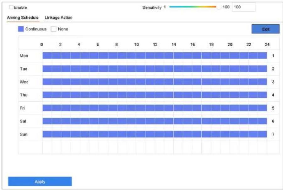
bar
| Day | Continuous | None | |---|---|---| | Mon | 1 | 0 | | Tue | 2 | 0 | | Wed | 3 | 0 | | Thu | 4 | 0 | | Fri | 5 | 0 | | Sat | 6 | 0 | | Sun | 7 | 0 | Apply Sensitivity 1 100 100 EditFigure 5-11 Defocus Detection
- Check Enable.
- Optional: Check Save VCA Picture to save the captured defocus detection pictures.
- Drag the Sensitivity slider to set the detection sensitivity.
Sensitivity
Ranges from 1 to 100, the higher the value, the more easily the defocus image will be detected.

Note
- Set the arming schedule. Refer to Configure Arming Schedule.
- Set the linkage actions. Refer to Configure Linkage Actions.
- Click Apply.
5.2.10 Sudden Scene Change Detection
Scene change detection detects the change of the surveillance environment affected by external factors, such as the intentional rotation of the camera.
Steps
- Go to Smart Analysis → Smart Event Settings → Other Events.
- Select a camera.
- Click Sudden Scene Change.
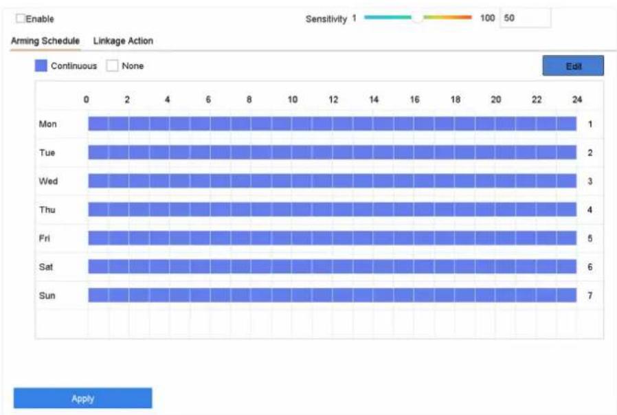
bar
| Day | Continuous | None | |---|---|---| | Mon | 1 | 24 | | Tue | 2 | 24 | | Wed | 3 | 24 | | Thu | 4 | 24 | | Fri | 5 | 24 | | Sat | 6 | 24 | | Sun | 7 | 24 |Figure 5-12 Sudden Scene Change
- Check Enable.
- Optional: Check Save VCA Picture to save the captured sudden scene change detection pictures.
- Drag the Sensitivity slider to set the detection sensitivity.
Sensitivity
Ranges from 1 to 100, the higher the value, the more easily the change of scene can trigger the alarm.

Note
- Set the arming schedule. Refer to Configure Arming Schedule.
- Set the linkage actions. Refer to Configure Linkage Actions.
- Click Apply.
5.2.11 PIR Alarm
A PIR (Passive Infrared) alarm is triggered when an intruder moves within the detector vision field. The heat energy dissipated by a person or any other warm blooded creature such as dogs, cats, etc., can be detected.
Steps
- Go to Smart Analysis → Smart Event Settings → Other Events.
- Select a camera.
- Click PIR Alarm.
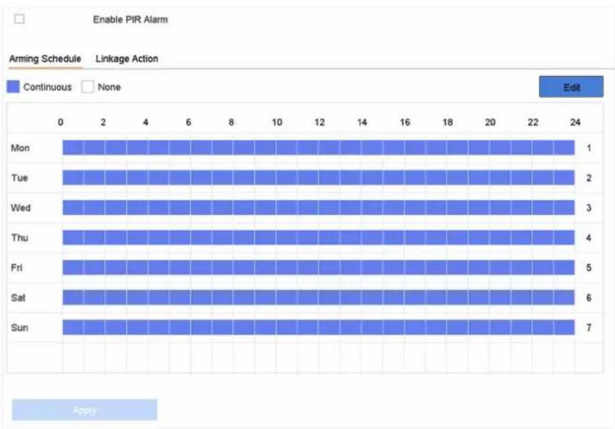
bar
| Day | Continuous | None | |---|---|---| | Mon | 1 | 0 | | Tue | 2 | 0 | | Wed | 3 | 0 | | Thu | 4 | 0 | | Fri | 5 | 0 | | Sat | 6 | 0 | | Sun | 7 | 0 | Enable PIR Alarm Arming Schedule Linkage Action Edit ApplyFigure 5-13 PIR Alarm
- Check PIR Alarm.
- Optional: Check Save VCA Picture to save the captured of PIR alarm pictures.
- Set the arming schedule. Refer to Configure Arming Schedule.
- Set the linkage actions. Refer to Configure Linkage Actions.
- Click Apply.
5.2.12 Thermal Camera Detection
The NVR supports the event detection modes of the thermal network cameras: fire and smoke detection, temperature detection, temperature difference detection, etc.
Before You Start
Add the thermal network camera to your device and make sure the camera is activated.
Steps
- Go to Smart Analysis → Smart Event Settings → Other Events.
- Select a thermal camera.
- Optional: Check Save VCA Picture to save the captured pictures of detection.
- Select an event detection (Temperature Measurement Alarm, etc.).
- Set the arming schedule. Refer to Configure Arming Schedule.
- Set the linkage actions. Refer to Configure Linkage Actions.
- Click Apply.
5.2.13 Configure Queue Management
After connecting with queue management camera, you can set the arming schedule and linkage action of queue management.
Before You Start
Ensure the recorder have connected with queue management camera.
Steps
- Go to Smart Analysis → Smart Event Settings → Other Events.
- Select a queue management camera.
- Optional: Check Save VCA Picture to save the captured pictures of detection.
- Set the arming schedule. Refer to Chapter Configure Arming Schedule for details.
- Set the linkage actions. Refer to Chapter Configure Linkage Actions for details.
- Click Apply.
5.3 Configure Arming Schedule
Steps
- Click Arming Schedule.
- Click Edit.
- Select a day of the week and set the time period. Up to eight time periods can be set each day.

Time periods cannot repeat or overlapped.
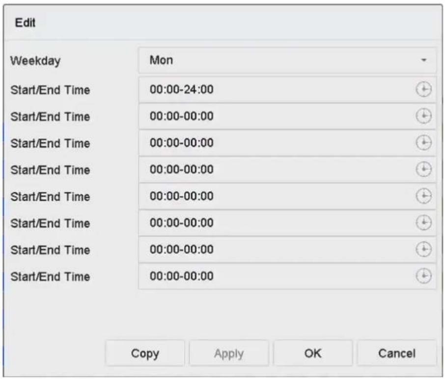
Figure 5-14 Set Arming Schedule
- You can click Copy to copy the current day arming schedule settings to other day(s).
- Click Apply to save the settings.
5.4 Configure Linkage Actions
Alarm linkage actions will be activated when an alarm or exception occurs, including Event Hint Display, Full Screen Monitoring, Audible Warning (buzzer), Notify Surveillance Center, Trigger Alarm Output, and Send Email.
5.4.1 Configure Auto-Switch Full Screen Monitoring
When an alarm is triggered, the local monitor displays in full screen the video image from the alarming channel configured for full screen monitoring. And when the alarm is triggered simultaneously in several channels, you must configure the auto-switch dwell time.

Auto-switch will terminate once the alarm stops and back to the live view interface.
Steps
- Go to System → Live View → General.
- Set the event output and dwell time.
Event Output
Select the output to show the event video.
Full Screen Monitoring Dwell Time
Set the time in seconds to show the alarm event screen. If alarms are triggered simultaneously in several channels, their full-screen images will be switched at an interval of 10 seconds (default dwell time).
- Go to the Linkage Action interface of the alarm detection (e.g., motion detection, video tampering, face detection, etc.).
- Select the Full Screen Monitoring alarm linkage action.
- Select the channel(s) in Trigger Channel for full screen monitoring.
5.4.2 Configure Audio Warning
The audio warning has the system to trigger an audible beep when an alarm is detected.
Steps
- Go to System → View → General.
- Enable the audio output and set the volume.
- Go to Linkage Action interface of the alarm detection (e.g., motion detection, video tampering, face detection, etc.).
- Select the Audio Warning alarm linkage action.
5.4.3 Notify Surveillance Center
The device can send an exception or alarm signal to the remote alarm host when an event occurs. The alarm host refers to the PC installed with client software (e.g., iVMS-4200, iVMS-5200).
Steps
- Go to System → Network → Advanced → More Settings.
- Set the alarm host IP and alarm host port.
- Go to Linkage Action interface of the alarm detection (e.g., motion detection, video tampering, face detection, etc.).
- Select Notify Surveillance Center.
5.4.4 Configure Email Linkage
The system can send an email with alarm information to a user or users when an alarm is detected.
Steps
- Go to System → Network → Advanced → Email.
- Set the email parameters.
-
Click Apply.
-
Go to the Linkage Action interface of the alarm detection (e.g., motion detection, video tampering, face detection, etc.).
- Select Send Email alarm linkage action.
5.4.5 Trigger Alarm Output
The alarm output can be triggered by the alarm input, motion detection, video tampering detection, face detection, line crossing detection, and any all other events.
Steps
- Go to Linkage Action interface of the alarm detection (e.g., motion detection, face detection, line crossing detection, intrusion detection, etc.).
- In Trigger Alarm Outputs Area, Select the alarm output (s) to trigger.
- Go to System → Event → Normal Event → Alarm Output.
- Select an alarm output item from the list.
5.4.6 Configure Audio and Light Alarm Linkage
For certain network cameras, you can set the alarm linkage action as audio alarm or light alarm.
Before You Start
- Ensure your camera supports audio and light alarm linkage.
- Ensure the audio output and volume are properly configured.
Steps
- Go to the linkage action interface of the alarm detection (e.g., motion detection).
- Set Audio and Light Alarm Linkage as your desire.
- Click Apply.
5.4.7 Configure PTZ Linkage
The system can trigger the PTZ actions (e.g., call preset/patrol/pattern) when the alarm event, or VCA detection events occurs.
Before You Start
Make sure the connected PTZ or speed dome connected supports PTZ linkage.
Steps
- Go to Linkage Action interface of the alarm input or VCA detection (e.g., face detection, line crossing detection, intrusion detection, etc.).
- Select the PTZ Linkage.
- Select the camera to perform the PTZ actions.
- Select the preset/patrol/pattern No. to call when the alarm events occur.

You can set only one PTZ type for the linkage action each time.
Chapter 6 Smart Analysis
6.1 Engine Configuration
Each engine processes a specified VCA type as its working mode. You can configure the engine working mode as your desire.
Steps
- Go to Smart Analysis → Engine Settings → Engine Configuration.
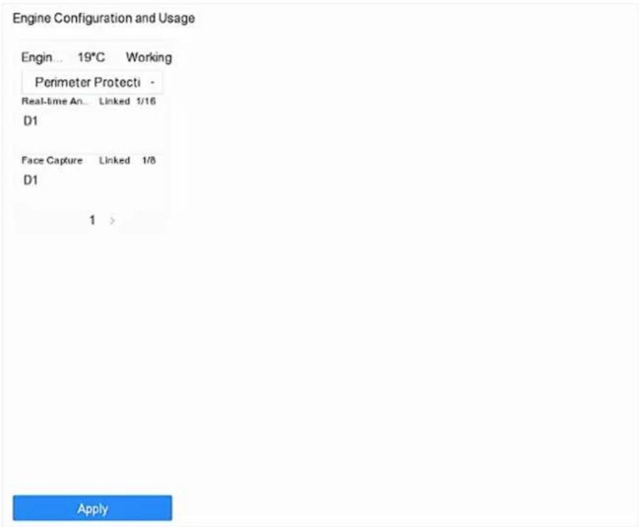
Figure 6-1 Engine Configuration
- Configure each engine usage. You can view the engine temperature and linked channel status of each function.

Note
If the engine has been bound with channel(s), switching engine working mode will unbind the engine and channel(s), and cancel the related smart event of the channel.
- Click Apply to save the settings.
6.2 Task Configuration
You can view the task status in task configuration. Smart analysis results are used for filtering the pictures when searching interested human body and vehicle pictures.
Before You Start
Check Save VCA Pictures for human body detection/vehicle detection, line crossing detection, intrusion detection, region entrance, or region exiting.
Steps

Note
The chapter is only available for certain models of iDS series.
- Go to Smart Analysis → Engine Settings → Task Configuration.
- Check cameras to enable corresponding analysis mode. Ensure engine is available for the selected analysis mode.
- Enable auto analysis.
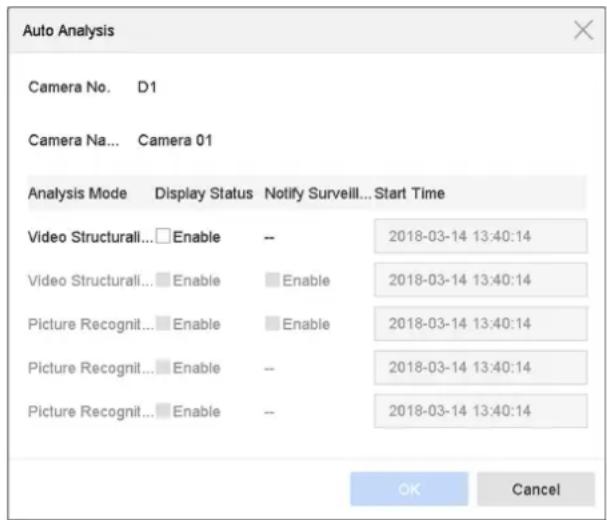
Figure 6-2 Auto Analysis
1) Click Edit.
2) Optional: Check Enable of Display Status and Notify Surveillance Center.
3) Set Start Time of video to analyze.
4) Click OK.
- Check cameras and click Enabled to start analyzing.
Task status includes 3 conditions: Disabled, Waiting, and Enabled.
Disabled
No analysis task is enabled on the camera.
Waiting
The analysis task of the camera is enabled. Device is waiting to analyze data.
Enabled
The analysis task of the camera is enabled and device is analyzing data of the camera.
- Optional: For Non-Real-Time Face Picture Comparison analysis mode, click View Record to view the progress of each day.
6.3 Face Picture Comparison
The device supports the face picture comparison alarm and face capture for the connected camera based on face recognition feature.
Go to Smart Analysis → Engine Settings → Engine Configuration. Configure at least one engine usage as Facial Recognition. Refer to Engine Configuration for details.

Note
The chapter is only available for certain models of iDS series.
6.3.1 Face Grading Configuration
Face grading is used for face picture selection. According to pupil distance, tilt angle and pan angle, it only uses face pictures which satisfy grading requirement for analysis. Larger pupil distance, smaller tilt and pan angle, better it would be for analysis.
Steps
- Go to Smart Analysis → Engine Settings → Face Grading.
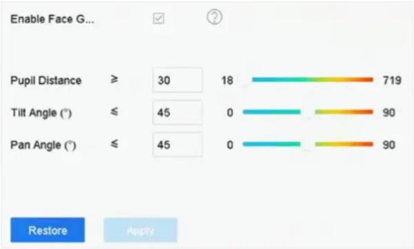
bar
| Variable | Value | |---|---| | Pupil Distance | 30 | | Tilt Angle (°) | 45 | | Pan Angle (°) | 45 | | Pupil Distance | 18 | | Tilt Angle (°) | 0 | | Pan Angle (°) | 0 | | Pupil Distance | 719 | | Tilt Angle (°) | 90 | | Pan Angle (°) | 90 | Restore | ApplyFigure 6-3 Face Grading
- Check Enable Face Grading.
- Set Pupil Distance, Tilt Angle, and Pan Angle.
Pupil Distance
Pupil distance is the distance between two pupils. In order to get better detection result, the pupil distance shall not be less than 40, and the recommended value is 60.
Tilt Angle
Tilt angle is the angle between your view and horizontal plane.
Pan Angle
Pan angle is the angle between your view and vertical plane.
4. Click Apply.
What to do next
- After face picture modeling, you can view face grading score of each face picture via web browser in Configuration → Face Picture Library.
- You can click √ in Smart Analysis → Face Picture Database to select face picture by face grading score.
6.3.2 Face Capture
The face capture detects and capture the face picture appearing in the surveillance scene. Linkage actions can be triggered when a human face is detected.
Steps
- Go to Smart Analysis → Smart Event Settings → Facial Recognition.
- Click Face Capture.
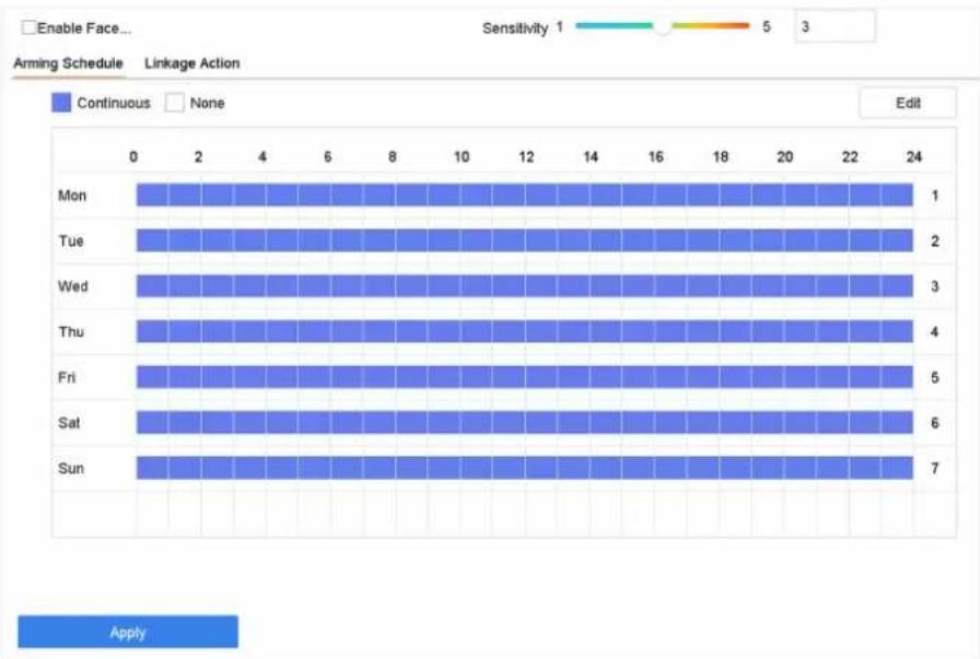
bar
| Day | Continuous | None | |---|---|---| | Mon | 1 | 0 | | Tue | 2 | 0 | | Wed | 3 | 0 | | Thu | 4 | 0 | | Fri | 5 | 0 | | Sat | 6 | 0 | | Sun | 7 | 0 | ApplyFigure 6-4 Face Capture
- Select a camera to configure.
- Check Enable Face Capture.
- Optional: Check Save VCA Picture to save the captured pictures of face detection.
-
Set the detection sensitivity. Sensitivity range: [1-5]. The higher the value is, the more easily the face will be detected.
-
Set the arming schedule. Refer to Configure Arming Schedule.
- Set linkage actions. Refer to Configure Linkage Actions.
- Click Apply.
6.3.3 Face Picture Library Management
Face picture library is mainly used for face picture storage and face picture comparison.
Add a Face Picture Library
Steps
- Go to Smart Analysis → Face Picture Database.
- Click + .
- Enter the face picture library name.
- Click OK.

You can click or to edit the library name or delete the library.
Upload Face Pictures to the Library
Face picture comparison is based on face pictures in the library. You can upload a single face picture or import multiple face pictures to the library.
Before You Start
- Ensure the picture format is JPEG or JPG.
- For each picture, ensure it only has one face.
- Import all pictures to a backup device in advance.
The picture must be in JPEG or JPG format.
Steps
- Select a face picture library in the list.
- Click Add or Import Face Picture Library.
- Import picture(s).
- Add:
Select a picture to import and click Import.
- Import Face Picture Library:
Select multiple pictures to import and click Import.
What to do next
- Select pictures and click Copy to to copy the uploaded pictures of the current library to other library.
- Select a picture and click Edit to modify the picture information.
- Select a picture from the list and click Delete to delete the picture.
- Select a library and click Export Face Picture Library to export library to backup device.
- Click or to view by figure or list.
Library for Strangers
All unrecognized face pictures will be added to Strangers library. This library cannot be deleted, and will be unavailable for stranger alarm when you select libraries.
The library name uses Strangers by default, you can edit the name as your desire. You can edit, delete, search, and export face pictures in this library. Face pictures in this library can be copy to other libraries. After copying face pictures to other libraries, you can delete them as your desire.
This library displays frequently appeared person frequency if you have lined this library with frequently appeared person alarm.
i Note
Ensure you have enabled frequently appeared person alarm. Refer to Frequently Appeared Person Alarm for details.
6.3.4 Face Picture Comparison Alarm
Configure Face Picture Comparison
Compare detected face pictures with specified face picture library. Trigger alarm when comparison succeeded.
Steps
- Go to Smart Analysis → Smart Event Settings → Facial Recognition.
- Select a camera.
- Click Face Picture Comparison.
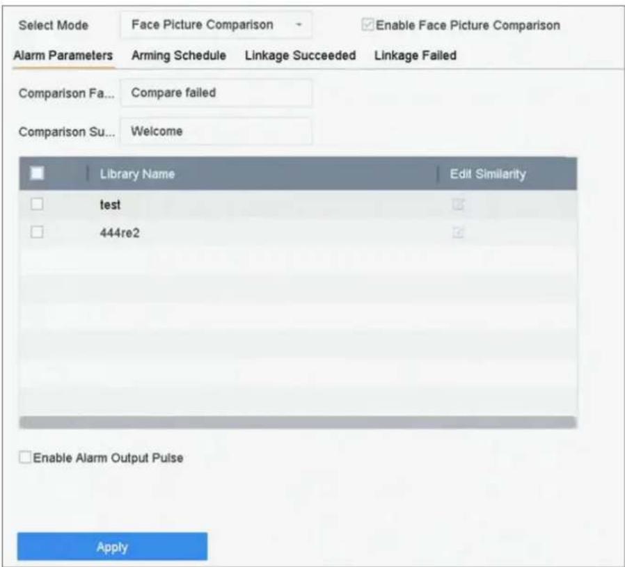
Figure 6-5 Face Picture Comparison
-
Set Mode as Face Picture Comparison.
-
Optional: Check Enable Non-Real-Time Mode. For places with a high flow of people, the device processing speed may not be fast enough, Non-Real-Time Mode will save the real-time pictures as cache, and process them later when engine has free resource. After enabling this function, all channels will be able to support face picture comparison.

Note
- When Non-Real-Time Mode is enabled, the linkage method will only support Notify Surveillance Center.
• Non-Real-Time Mode will not trigger real-time alarm, so Arming Schedule is unavailable. -
You can search the comparison event results in File Management → Smart Search → Face Search → Search by Event.
-
Check Enable Face Picture Comparison.
-
Optional: Check Save VCA Picture to save the captured pictures of VCA detection. After the face picture comparison is enabled, the comparison results will be uploaded for face comparison alarm. If the comparison produced a match, both the real-time face picture and the target picture from the library will be uploaded. If no match is produced, the real-time face picture is uploaded to center only. Up to 6 connected cameras can be configured for face picture comparison simultaneously.
-
Optional: Set Comparison Failed Prompt, Comparison Succeeded Prompt, and Enable Alarm Output Pulse.
Comparison Failed Prompt
It will display the prompt in live view Target Detection (with Facial Detection checked) or Facial Recognition when face picture comparison failed. You can click 📷 in live view to enter Facial Recognition interface.
Comparison Succeeded Prompt
It will display the prompt in Facial Recognition when face picture comparison succeeded. You can click 📄 in live view to enter Facial Recognition interface.
Enable Alarm Output Pulse
It is usually linked with a gate. When a person is passing a gate, if the comparison succeeded, it will trigger a pulse to open the gate. The pulse is between 100 to 900 ms. You can set Alarm Output Pulse (ms) in System → Event → Normal Event → Alarm Output.
-
Select face picture libraries and set similarity.
-
Set the arming schedule. Refer to Configure Arming Schedule.
-
Set the linkage actions when face picture comparison succeeded or failed. Refer to Configure Linkage Actions.
-
Optional: Configure face grading parameters. Refer to Face Grading Configuration.
-
Click Apply to save the settings.
Configure Stranger Alarm
Compare detected face pictures with specified face picture library. Trigger alarm when comparison failed.
Steps
- Go to Smart Analysis → Smart Event Settings → Facial Recognition.
- Select a camera.
- Click Face Picture Comparison.
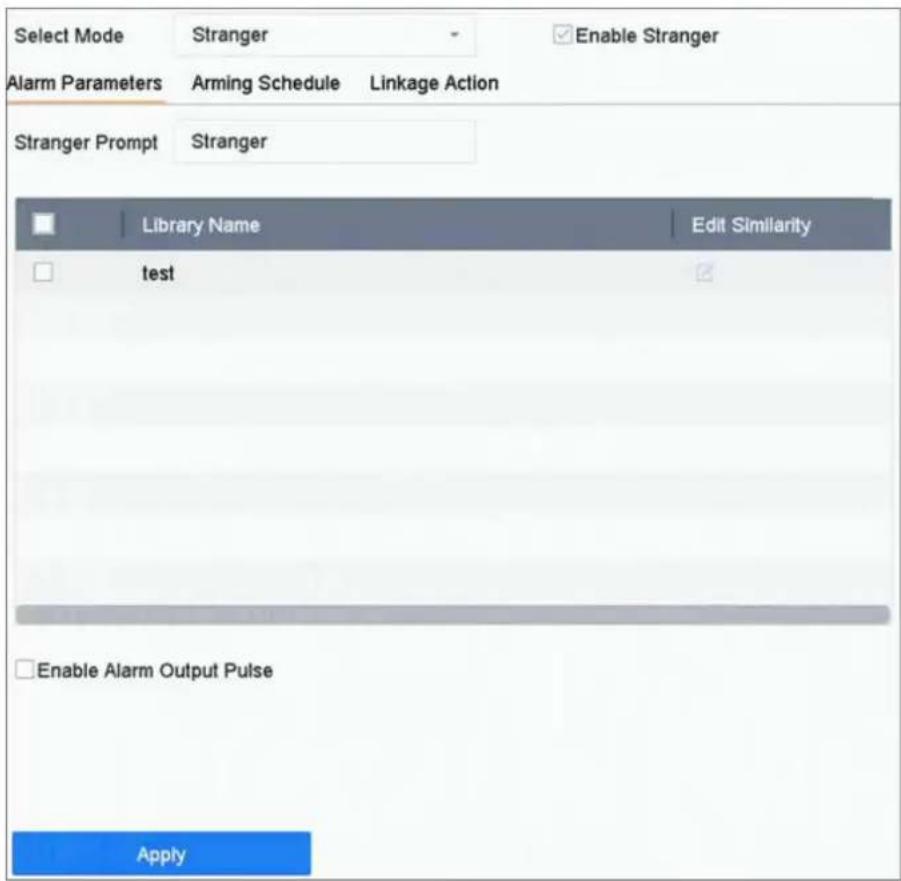
Figure 6-6 Face Picture Comparison
-
Select Mode as Stranger.
-
Optional: Check Enable Non-Real-Time Mode. For places with a high flow of people, the device processing speed may not be fast enough, Non-Real-Time Mode will save the real-time pictures as cache, and process them later when engine has free resource. After enabling this function, all channels will be able to support face picture comparison.

Note
- When Non-Real-Time Mode is enabled, the linkage method will only support Notify Surveillance Center.
• Non-Real-Time Mode will not trigger real-time alarm, so Arming Schedule is unavailable. -
You can search the comparison event results in File Management → Smart Search → Face Search → Search by Event.
-
Check Enable Stranger.
-
Optional: Check Save VCA Picture to save the captured pictures of VCA detection. After the face picture comparison is enabled, the comparison results will be uploaded for face comparison alarm. If the comparison produced a match, both the real-time face picture and the target picture from the library will be uploaded. If no match is produced, the real-time face picture is uploaded to center only.
-
Optional: Set Stranger Prompt. It will display the prompt in live view Target Detection (Facial Detection) when comparison failed.
Stranger Prompt
It will display the prompt in live view Target Detection (with Facial Detection checked) when face picture comparison failed.
Enable Alarm Output Pulse
It is usually linked with a gate. When a person is passing a gate, if the comparison succeeded, it will trigger a pulse to open the gate. The pulse is between 100 to 900 ms. You can set Alarm Output Pulse (ms) in System → Event → Normal Event → Alarm Output.
-
Select face picture libraries and set similarity.
-
Set the arming schedule. Refer to Configure Arming Schedule.
-
Set the linkage actions. Refer to Configure Linkage Actions.
-
Optional: Configure face grading parameters. Refer to Face Grading Configuration.
-
Click Apply to save the settings.
6.3.5 People Frequency Alarm
You can only configure people frequency alarm via web browser.
Frequently Appeared Person Alarm
It will trigger alarm when a person has appeared at a high frequency.
Steps
- Go to Configuration → Event → People Frequency → Frequently Appeared Person.
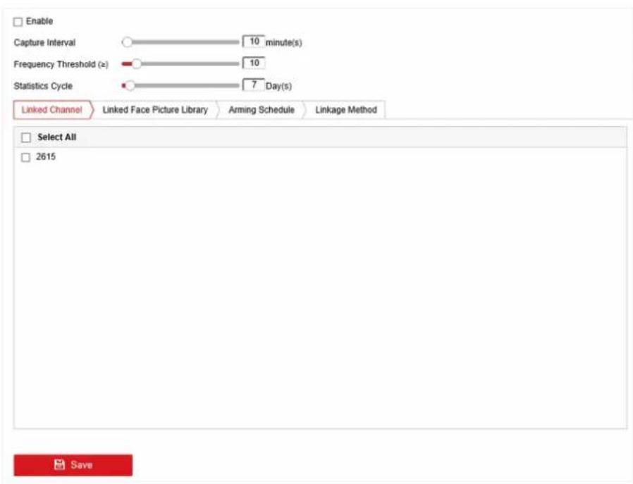
Figure 6-7 Frequently Appeared Person
- Check Enable.
- Set Capture Interval, Frequency Threshold, and Statistics Cycle.
Capture Interval
When a person has appeared several times within the capture interval, it only counts 1 time for this person.
Frequency Threshold
It will trigger alarm when the frequency has exceeded the threshold.
Statistics Cycle
Time period for counting the people frequency. For example, if the statistics cycle is 7 days, device will count people frequency in the last 7 days (including today), if a person has exceeded the frequency threshold in the last 7 days, it will trigger alarm.
- Click Linked Channel to select channel.
- Click Linked Face Picture Library to select face picture library
- Set similarity for the selected library.
- Set strategy as Filter or Alarm.
Filter
If the face picture similarity has exceeded the value, the face picture is considered as an existing member in the library, which will not trigger alarm.
Alarm
It will trigger alarm when the face picture similarity and frequency has exceeded the threshold.

Note
All unrecognized face pictures will be added to Strangers library, so that strangers can also trigger the frequently appeared person alarm, and they use the similarity of Strangers library.
- Set the arming schedule. Refer to Configure Arming Schedule.
- Set linkage actions. Refer to Configure Linkage Actions.
- Click Save.
Rarely Appeared Person Alarm
It will trigger alarm when a person has appeared at a low frequency.
Steps
- Go to Configuration → Event → People Frequency → Low Frequency Person.
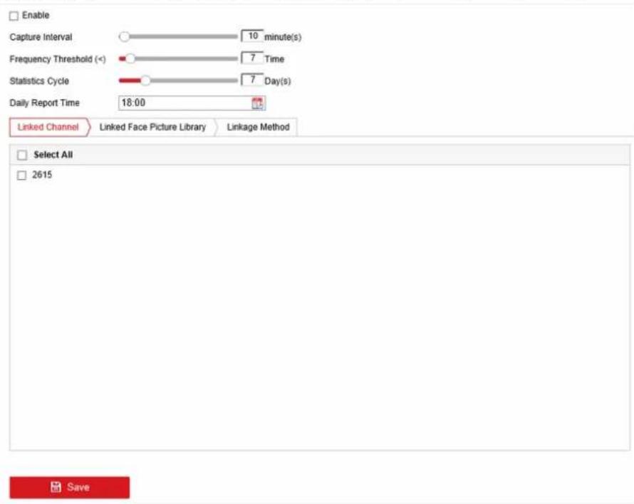
Figure 6-8 Rarely Appeared Person
- Check Enable.
- Set Capture Interval, Frequency Threshold, Statistics Cycle, and Daily Report Time.
Capture Interval
When a person has appeared several times within the capture interval, it only counts 1 time for this person.
Frequency Threshold
It will trigger alarm when the frequency has not reached the threshold.
Statistics Cycle
Time period for counting the people frequency. For example, if the statistics cycle is 7 days, device will count people frequency in the last 7 days (including today), if a person has not exceeded the frequency threshold in the last 7 days, it will trigger alarm.
Daily Report Time
Daily report low frequency person statistics at the predefined time.
- Click Linked Channel to select channel.
- Click Linked Face Picture Library to select face picture library
- Set similarity for the selected library.
- Set linkage actions. Refer to Configure Linkage Actions.
- Click Save.
6.3.6 Face Picture Search
Search by Face Picture Comparison Event
Search face picture by face picture comparison results.
Steps
- Go to Smart Analysis → Smart Search → Face Search → Search by Event.
- Set the start time and end time.
- Select a channel.
- Select Event Type as Face Picture Comparison.
- Click Start Search. The search result list displays 1 channel.
- Click Channel to select a channel as your desire. It will display search results for the selected channel.
What to do next
Refer to View Searching Result.
Search by Uploaded Picture
You can search the face pictures by uploaded picture.
Steps
- Go to Smart Analysis → Smart Search → Face Search → Search by Picture.
![Upload Sample from Local Upload Sample from Face Picture Database Not more than 5 pictures for sample cache.0/9 IP Channel [AI] Camera Time Segment Today - 2020-01-13 00:00 - 2020-01-13 23:59 Similarity(50~100) > 80 Start Search](/content/2026/06/1194368/images/95246fa1dc2146a47ca89d14653171322264fd65712ed67dc442b387ac02830c.jpg)
Figure 6-9 Search by Uploaded Picture
- Select a channel.
-
Select face pictures for search.
-
Click Upload Sample from Local and select face pictures from your local directory.
-
Click Upload Sample from Face Picture Database and select face pictures from created face picture libraries.
-
Set the start time and end time.
-
Set the Similarity value (range: 0 to 100). Device will analyze the similarity between samples and face pictures in library and show pictures the similarity of which are higher than the set one.
- Click Start Search. The search result list displays 1 channel.
- Click Channel to select a channel as your desire. It will display search results for the selected channel.
What to do next
Refer to View Searching Result.
Search by Personal Name
Search face picture by personal name.
Steps
- Go to Smart Analysis → Smart Search → Face Search → Search by Name.
![IP Channel [All] Camera Time Segment Today 2020-01-13 00 00 - 2020-01-13 23:59 Name Start Search](/content/2026/06/1194368/images/df5af56057ddf076af006d6fde0e1e7c19fd8fec662129c87d84f5059c0c735f.jpg)
Figure 6-10 Search by Personal Name
- Set the start time and end time of the face pictures to search.
- Select a channel.
- Enter a name.
- Click Start Search. The search result list displays 1 channel.
- Click Channel to select a channel as your desire. It will display search results for the selected channel.
What to do next
Refer to View Searching Result.
Search by Appearance
Search face picture by appearance.
Steps
- Go to Smart Analysis → Smart Search → Face Search → Search by Appearance.
- Set search conditions.
- Click Start Search. The search result list displays 1 channel.
- Click Channel to select a channel as your desire. It will display search results for the selected channel.
What to do next
Refer to View Searching Result.
View Searching Result
- Double click a file to view the related video.
- Click Add to Face Database to add the selected file(s) to a face picture library.
- Click Add to Sample to add the select file(s) as sample picture(s). You can use the sample picture(s) to search other pictures. Refer to Search by Uploaded Picture.
- Click Export to export the selected file(s) to a backup device. You can click Select All to select all files.
i Note
- You can click 📄 to view export progress.
- You can click to return to search interface.
6.4 Perimeter Protection
For certain models of iDS series. Go to Smart Analysis → Engine Settings → Engine Configuration. Configure at least one engine usage as Perimeter Protection. Refer to Engine Configuration for details.
6.4.1 Line Crossing Detection
Line crossing detection detects people, vehicles, and objects crossing a set virtual line. The detection direction can be set as bidirectional, from left to right or from right to left.
Steps
- Go to Smart Analysis → Smart Event Settings → Perimeter Protection.
- Select a camera.
- Click Line Crossing.
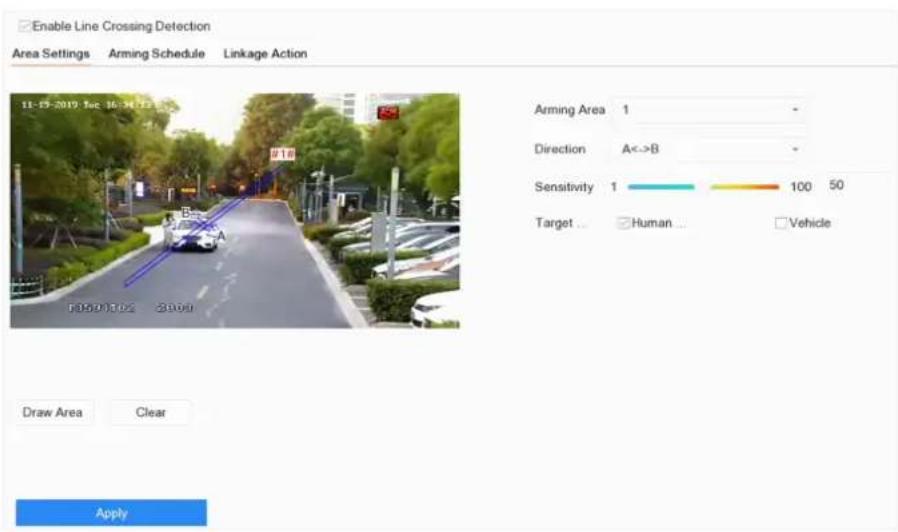
Figure 6-11 Line Crossing Detection
-
Check Enable Line Crossing Detection.
-
Optional: Check Save VCA Picture to save the captured pictures of line crossing detection.
-
Optional: Check Enable AI by Device. The device will analyze the video, cameras only transmit video stream.
-
Set the line crossing detection rules and detection areas.
1) Select an arming area.
2) Select Direction as A<->B, A->B, or A<-B.
A<->B
Only the arrow on the B side shows. When an object goes across the configured line with both directions can be detected and alarms are triggered.
A->B
Only the object crossing the configured line from the A side to the B side can be detected.
B->A
Only the object crossing the configured line from the B side to the A side can be detected.
3) Set the detection sensitivity. The higher the value is, the more easily the detection alarm can be triggered.
4) Click Draw Region.
5) Draw a virtual line in the preview window.
- Optional: Draw the maximum size/minimum size for targets. Only the targets in the size ranging from maximum size to minimum size will trigger line crossing detection.
1) Click Max. Size/Min. Size.
2) Draw an area in preview window.
3) Click Stop Drawing.
-
Optional: Select Target of Interest as Human Body or Vehicle to discard alarms which are not triggered by human body or vehicle.
-
Set the arming schedule. Refer to Configure Arming Schedule.
-
Set linkage actions. Refer to Configure Linkage Actions.
-
Click Apply.
6.4.2 Intrusion Detection
The Intrusion detection function detects people, vehicles or other objects that enter and loiter in a pre-defined virtual region. Specific actions can be taken when an alarm is triggered.
Steps
- Go to Smart Analysis → Smart Event Settings → Perimeter Protection.
- Select a camera.
- Click Intrusion.

Figure 6-12 Intrusion Detection
- Check Enable Intrusion Detection.
- Optional: Check Save VCA Picture to save the captured intrusion detection pictures.
- Optional: Check Enable AI by Device. The device will analyze the video, cameras only transmit video stream.
- Set the detection rules and detection areas.
1) Select a virtual panel. Up to 4 virtual panels are selectable.
2) Set Time Threshold, and Sensitivity.
Time Threshold
The time an object loiter in the region. When the duration of the object in the defined detection area exceeds the threshold, the device will trigger an alarm.
Sensitivity
The size of the object that can trigger the alarm. The higher the value is, the more easily the detection alarm will be triggered.
3) Click Draw Area.
4) Draw a quadrilateral in the preview window.
- Optional: Draw the maximum size/minimum size for targets. Only the targets in the size ranging from maximum size to minimum size will trigger line crossing detection.
1) Click Max. Size/Min. Size.
2) Draw an area in preview window.
3) Click Stop Drawing.
-
Optional: Select Target of Interest as Human Body or Vehicle to discard alarms which are not triggered by human body or vehicle.
-
Set the arming schedule. Refer to Configure Arming Schedule.
-
Set linkage actions. Refer to Configure Linkage Actions.
-
Click Apply.
6.4.3 Region Entrance Detection
Region entrance detection detects objects that enter a predefined virtual region.
Steps
- Go to Smart Analysis → Smart Event Settings → Perimeter Protection.
- Select a camera.
- Click Region Entrance Detection.
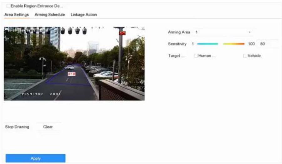
Figure 6-13 Region Entrance Detection
- Check Enable Region Entrance Detection.
- Optional: Check Save VCA Picture to save the captured pictures of region entrance detection pictures.
- Optional: Check Enable AI by Device. The device will analyze the video, cameras only transmit video stream.
- Set detection rules and detection areas.
1) Select Arming Region. Up to 4 regions are selectable.
2) Set Sensitivity. The higher the value is, the easier the detection alarm will be triggered. Its range is [0-100].
3) Click Draw Region, and draw a quadrilateral in the preview window.
- Optional: Draw the maximum size/minimum size for targets. Only the targets in the size ranging from maximum size to minimum size will trigger line crossing detection.
1) Click Max. Size/Min. Size.
2) Draw an area in preview window.
3) Click Stop Drawing.
-
Optional: Select Target of Interest as Human Body or Vehicle to discard alarms which are not triggered by human body or vehicle.
-
Set the arming schedule. Refer to Configure Arming Schedule.
- Set linkage actions. Refer to Configure Linkage Actions.
- Click Apply.
6.4.4 Region Exiting Detection
Region exiting detection detects objects that exit from a predefined virtual region.
Steps
- Go to Smart Analysis → Smart Event Settings → Perimeter Protection.
- Select a camera.
- Click Region Exiting.
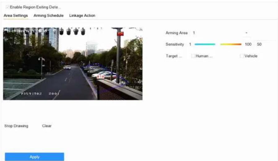
Figure 6-14 Region Exiting Detection
- Check Enable Region Exiting Detection.
- Optional: Check Save VCA Picture to save the captured region exiting detection pictures.
- Optional: Check Enable AI by Device. The device will analyze the video, cameras only transmit video stream.
- Follow these steps to set the detection rules and detection areas.
1) Select Arming Region. Up to 4 regions are selectable.
2) Set Sensitivity. The higher the value is, the more easily the detection alarm will be triggered. Its range is [0-100].
3) Click Draw Region and draw a quadrilateral in the preview window.
- Optional: Draw the maximum size/minimum size for targets. Only the targets in the size ranging from maximum size to minimum size will trigger line crossing detection.
1) Click Max. Size/Min. Size.
2) Draw an area in preview window.
3) Click Stop Drawing.
-
Optional: Select Target of Interest as Human Body or Vehicle to discard alarms which are not triggered by human body or vehicle.
-
Set the arming schedule. Refer to Configure Arming Schedule.
- Set linkage actions. Refer to Configure Linkage Actions.
- Click Apply.
6.5 Human Body Detection
Go to Smart Analysis → Engine Settings → Engine Configuration. Configure at least one engine usage as Picture Recognition-Human Body. Refer to Engine Configuration for details.
Go to Smart Analysis → Engine Settings → Task Configuration to enable the task for camera. For details, refer to Task Configuration for details.
i Note
The chapter is only available for certain models of iDS series.
6.5.1 Human Body Detection
The human body detection enables to detect the human body appearing in the monitoring scene, and capture the human body pictures.
Before You Start
Ensure the connected camera supports the human body detection.
Steps
- Go to Smart Analysis → Smart Event Settings → Other Events.
- Select a camera.
- Click Human Body.
- Optional: For IP camera does not support human body detection, Check Enable Local Human Body Detection. Then the device will consume its decoding resource to execute human body detection. Before enabling the function, go to Smart Analysis → Engine Settings → Engine Configuration to select at least one engine as Video Structuralization-Real-Time.
- Check Save VCA Picture to save the captured pictures of human body detection.
- Check Target of Interest (Human Body) to discard non-human body pictures and videos which are not triggered by human body detection. The feature is only available for local human body detection.
- Set detection area.
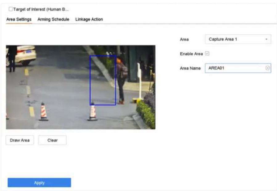
Figure 6-15 Human Body Detection
1) Select the detection area to configure from the Area drop-down list. Up to 8 detection areas are selectable.
2) Check Enable Area to enable the selected detection area.
3) Edit the area name in Scene Name. The scene name can contain up to 32 characters.
4) Click Draw Area to draw a quadrilateral in the preview window and then click Stop Drawing.
-
Set the arming schedule. Refer to Configure Arming Schedule.
-
Set linkage actions. Refer to Configure Linkage Actions.
- Click Apply to activate the settings.
6.5.2 Human Body Search
Search by Human Body Event
Search pictures by human body detection alarms.
Steps
- Go to Smart Analysis → Smart Search → Human Body Search → Search by Event.
- Set the start time and end time.
- Select a channel.
- Select Event Type as Human Body Alarm.
- Click Start Search. The search result list displays 1 channel.
- Click Channel to select a channel as your desire. It will display search results for the selected channel.
- Optional: Export search results.
1) Select result file(s) from the search result interface, or check Select All to select all files.
2) Click Export to export the selected file(s) to a backup device.

Note
- You can click 📄 to view export progress.
- You can click to return to search interface.
Search by Appearance
Search human body pictures according to manually specified search conditions.
Steps
- Go to Smart Analysis → Smart Search → Human Body Detection → Search by Appearance.
- Specify search conditions.
- Click Start Search. The search result list displays 1 channel.
- Click Channel to select a channel as your desire. It will display search results for the selected channel.
- Optional: Export search results.
1) Select result file(s) from the search result interface, or check Select All to select all files.
2) Click Export to export the selected file(s) to a backup device.

Note
- You can click 📄 to view export progress.
- You can click to return to search interface.
Search by Uploaded Picture
To increase search accuracy, upload several pictures of one person to compare with captured human body pictures.
Before You Start
Import human body pictures in a USB flash drive and connect it to device.
Steps

Note
- When there are multiple targets existing in the same picture, up to 30 target pictures can be analyzed and displayed.
- The maximum allowed picture size is 3840*2160.
- The picture must be in JPG or JPEG format.
- The picture name (with the suffix) cannot exceed 64 characters.
-
Ensure the picture you uploaded is clear and recognizable.
-
Go to Smart Analysis → Smart Search → Human Body Detection → Search by Picture.
-
Select a channel.
- Click Upload Sample.
- Click Upload Sample from Local and select face pictures from your local directory.
- Set the start time and end time.
- Select a picture in USB flash drive, and click Import.
- Select related pictures, and click Upload.
- Specify search conditions.
Similarity
Device will analyze the similarity between samples and face pictures in library and show pictures the similarity of which are higher than the set one.
-
Click Start Search. The search result list displays 1 channel.
-
Optional: Export search results.
1) Select result file(s) from the search result interface, or check Select All to select all files.
2) Click Export to export the selected file(s) to a backup device.

Note
- You can click 📄 to view export progress.
- You can click to return to search interface.
Add Search Result as Sample Picture
You can add searched human body pictures as sample pictures. And then search human body pictures by the sample pictures.
Steps
- Search human body pictures.
- In search result interface, click to select a picture and click Add to Sample.
- Return to search condition settings interface, the selected sample will be listed.
6.6 Multi-Target-Type Detection
Multi-target-type detection enables the device to detect the faces, human bodies and vehicles simultaneously in a scene.
Before You Start
Go to Smart Analysis → Engine Settings → Engine Configuration to configure at least one engine usage as Video Structuralization-Real-Time. Refer to Engine Configuration for details.
Steps
- Go to Smart Analysis → Smart Event Settings → Video Structuralization.
- Select a camera.
-
Check Enable Multi-Target-Type Detection.
-
Optional: Check Save VCA Picture to save the captured intrusion detection pictures.
-
Optional: Check Enable NVR Smart Analysis. The device will analyze the video, cameras only transmit video stream.
-
Set detection area.
1) Click Draw Area.
2) Adjust the red frame on the image to draw the detection area. It is full screen by default.
3) Click Stop Drawing.
-
Optional: Set Capture Quality. The captured picture will be stored to the device, high quality brings higher resolution, but it takes larger storage space. Picture quality will not affect detection accuracy.
-
Set the arming schedule. Refer to Configure Arming Schedule.
-
Set the linkage method. Refer to Configure Linkage Actions.
-
Click Apply.
6.7 Vehicle Detection
Vehicle detection is available for the road traffic monitoring. In vehicle detection, the passed vehicle can be detected and the picture of its license plate can be captured. You can send alarm signal to notify the surveillance center and upload the captured picture to FTP server.
6.7.1 Configure Vehicle Detection
Vehicle detection is available for road traffic monitoring. In Vehicle Detection, a passed vehicle can be detected and the picture of its license plate can be captured. You can send an alarm signal to notify the surveillance center and upload the captured picture to an FTP server.
Steps
- Go to Smart Analysis → Smart Event Settings → Vehicle Detection.
- Select a camera.
- Click Vehicle.
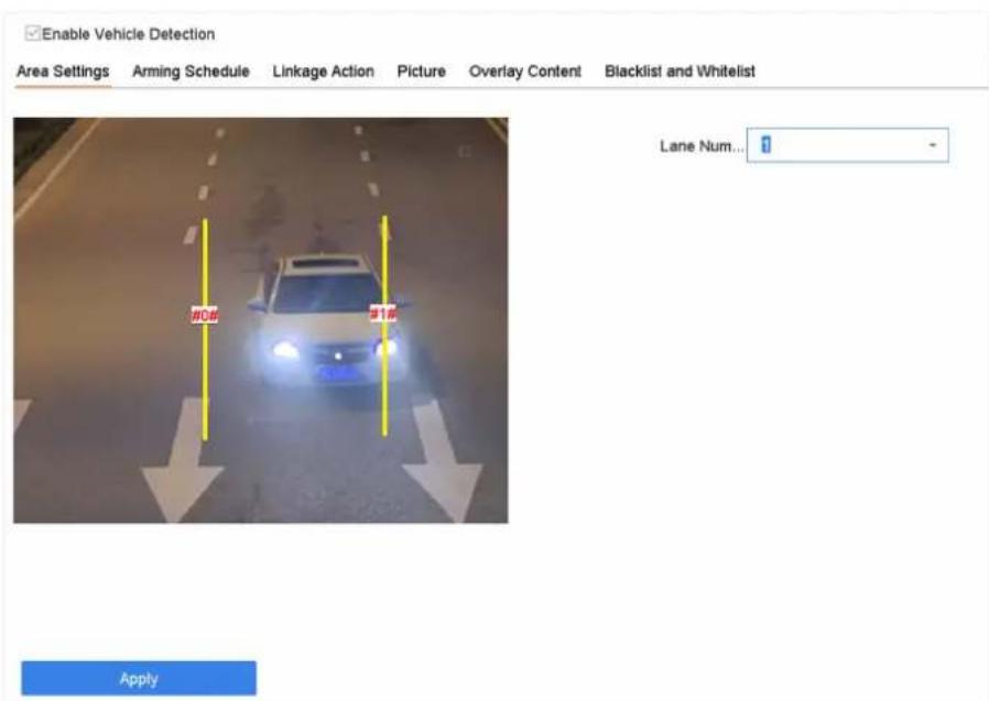
Figure 6-16 Vehicle Detection
- Check Enable Vehicle Detection.
- Optional: Check Save VCA Picture to save the captured vehicle detection pictures.
- Configure rules, including Area Settings, Picture, Overlay Content, and Blacklist and Whitelist.
Area Settings
Up to 4 lanes are selectable.
Blacklist and Whitelist
You can export the file first to see its format, and edit it and import it to the device.
- Click Apply.

Note
Refer to the Network Camera User Manual for detailed instructions for the vehicle detection.
- Set the arming schedule. Refer to Configure Arming Schedule
- Set the linkage actions. Refer to Configure Linkage Actions
6.7.2 Vehicle Search
You can search and view the matched vehicle pictures.
Steps
- Go to Smart Analysis → Smart Search → Vehicle Search.
- Select the IP camera for the vehicle search.
- Set search conditions.
![Search by Appearance IP Channel [All] Camera Time Segment Today 2017-09-19 00:00:00 2017-09-19 23:59:59 Vehicle Brand All Vehicle Color All Vehicle Model All License Plate N...](/content/2026/06/1194368/images/55f57c8f5e35c6c6d938c14fb031b59069b52c6fb27e716807ae2fda4bddff03.jpg)
Figure 6-17 Vehicle Search
-
Click Start Search. The search result list displays 1 channel.
-
Click Channel to select a channel as your desire. It will display search results for the selected channel.
-
Export search results.
1) Select result file(s) from the search result interface, or check Select All to select all files.
2) Click Export to export the selected file(s) to a backup device.

You can click to view export progress.
6.8 Target Detection
In live view mode, the target detection function can achieve smart detection, facial detection, vehicle detection, and human body detection during the last 5 seconds and the following 10 seconds.
Steps
-
In Live View mode, click Target Detection to enter the target detection interface.
-
Select different detection types: smart detection (☐), vehicle detection (☒), face detection (☐), and human body detection (☐)
-
Select the historical analysis ( ) or real-time analysis ( ) to obtain the results.

The smart analysis results of the detection are displayed in the list. Click a result in list to play the related video.
- Optional: You can select channels that require picture capture. The unselected channels will not capture picture.
1) Click 📄 at the left bottom of live view interface.
2) Select channel(s), the checked channel(s) will capture picture. All channels are selected as default.
3) Click Finish.
6.9 People Counting
Counting calculates the number of people entering or leaving a certain configured area and creates daily/weekly/monthly/annual reports for analysis.
Steps
- Go to Smart Analysis → Smart Report → Counting.
- Select the camera(s).
- Select the report type.
- Set Date to analyze. The people counting graphic will show.
![Counting Host Map Camera [D:\]iPCamera 01 Daily Report Weekly Report Monthly Report Annual Report Due: 25-09-2017 People Entered People Ended](/content/2026/06/1194368/images/fc3326c65b7d15094369c03fa8d647da8886a18e53f1c86240c5e49ef420610d.jpg)
Figure 6-18 People Counting Interface
- Optional: Click Export to export the report in Microsoft Excel format.
6.10 Heat Map
Heat Map is a graphical representation of data. The heat map function is used to analyze how many people visited and stayed in a specific area.
Before You Start
The Heat Map function must be supported by the connected IP camera and the corresponding configuration must be set.
Steps
- Go to Smart Analysis → Smart Report → Heat Map.
- Select a camera.
- Select the report type.
- Set Date to analyze.
![Counting New Map Camera [D1] PCamera 01 Daily Report Weekly Report Monthly Report Annual Report Data 25-09-2017 Counting Export 12-04-2014](/content/2026/06/1194368/images/aee5c8191ff469c0c77b0dd1d099a31ce335bfa66ba2bcce75025a54b527b9df.jpg)
Figure 6-19 Heat Map Interface
- Click Counting. The results will be displayed in graphics marked in different colors.

Note
As shown in the figure above, red color block (255, 0, 0) indicates the most trafficked area, and blue color block (0, 0, 255) indicates the less-popular area.
- Optional: Click Export to export the statistics report in Microsoft Excel format.
Chapter 7 File Management
7.1 Search Files
Specify detailed conditions to search videos and pictures.
Steps
- Go to File Management → Video, or File Management → Picture.
- Select a search method. For example, Search by Appearance, or Search by Event.
- Specify detailed conditions, including time, camera, etc.
- Click Start Search.
- Click Channel to select a channel as your desire. It will display the searching results of the selected channel.
- Optional: Click or to switch view mode.
- Optional: For videos, click 📷 or 🔒 in different view mode to lock a video. The locked video will not be overwritten.
- Optional: Export search results.
1) Select result file(s) from the search result interface, or check Select All to select all files.
2) Click Export to export the selected file(s) to a backup device.

- You can click 📄 to view export progress.
• You can click ↓ to return to search interface.
7.2 Export Files
Export files for backup purposes to a USB device, or eSATA HDD.
Steps
- Search files. Refer to Search Files for details.
- Select files.
- Click Export.
- Optional: For vehicle files, check Backup License Plate Statistics Info to export license plate statistics information later.
- Select the file to export as Video and log and click OK.
- Select the backup device and folder path.
- Click OK.
7.3 Smart Search
You can search human body files, face files and vehicles in File Management → Smart Search. Refer to Human Body Search Face Picture Search, and Vehicle Search for details.
Chapter 8 Storage
8.1 Storage Device Management
8.1.1 SSD Management
Initialize SSD
For the device that has pre-installed SSD on main board, you can view the SSD space distribution or initialize the SSD.
Steps
- Go to Storage → Storage Management → SSD Management.
- Click Format.
- Click Yes to initialize SSD.

Note
Initializing SSD will erase its data, including those in face picture library, and cancel the alarms linked to the library. The device will restart after initialization.
SSD S.M.A.R.T. Detection
Self-monitoring, analysis, and reporting technology (S.M.A.R.T.) is a monitoring system included in computer hard disk drives (HDDs) and solid-state drives (SSDs) that detects and reports on various indicators of drive reliability, with the intent of enabling the anticipation of hardware failures. You can run the S.M.A.R.T. detection for your SSD.
Steps
- Go to Maintenance → HDD Operation → S.M.A.R.T
- Set HDD No. as SSD.
- Set Self-Test Type.
- Click Self-Test to start the S.M.A.R.T. SSD self-evaluation.
Upgrade SSD Firmware
You can use a USB flash drive to upgrade your SSD firmware.
Before You Start
Prepare a USB flash drive that contains the SSD firmware, and insert the USB flash drive to your device USB interface.
Steps
- Go to Storage → Storage Management → SSD Management.
- Click Firmware Upgrade.
- Select Device Name as the USB flash drive that contains the SSD firmware.
- Select the SSD firmware.
- Click Upgrade.
8.1.2 Manage Local HDD
Configure HDD Group
Multiple HDDs can be managed in groups. Video from specified channels can be recorded onto a particular HDD group through HDD settings.
Steps
- Go to Storage → Storage Mode.
- Select Mode as Group.
- Click Apply.
- Go to Storage → Storage Device.
- Select a HDD.
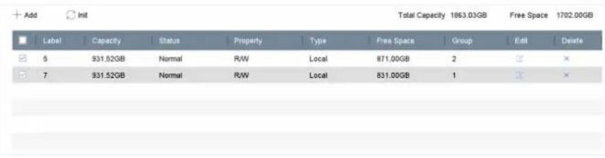
Figure 8-1 Storage Device
- Click to enter Local HDD Settings interface.
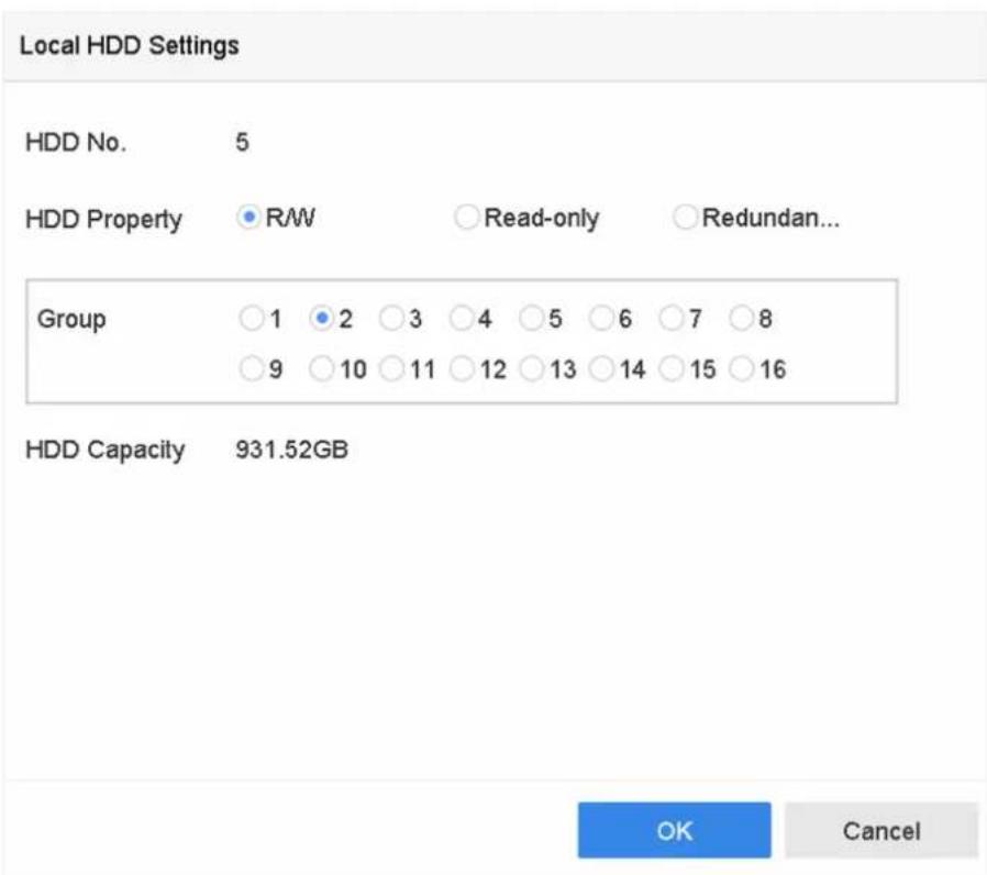
Figure 8-2 Local HDD Settings
- Select a group number for the HDD.
- Click OK.

Regroup the cameras for HDD if the HDD group number is changed.
- Go to Storage → Storage Mode.
- Select group number from the list.
- Select related camera(s) to save videos and pictures on the HDD group.
- Click Apply.
Configure the HDD Property
HDD property can be set as R/W, Read-only, or Redundant.
Before You Start
Set the storage mode to Group. For detailed steps, refer to Configure HDD Group
Steps
- Go to Storage → Storage Device.
- Click ☑ of desired HDD.
- Select HDD Property.
R/W
HDD supports both read and write.
Read-only
Files in read-only HDD will not be overwritten.
Redundant
Save the videos and pictures not only in the R/W HDD but also in the redundant HDD. It effectively enhances the data safety and reliability. Ensure at least another HDD which is in Read/Write status exists.
4. Click OK.
Configure the HDD Quota
Each camera can be configured with an allocated quota for storing videos or pictures.
Steps
-
Go to Storage → Storage Mode.
-
Select Mode as Quota.
-
Select a camera to set quota.
-
Enter the storage capacity in the text fields of Max. Record Capacity (GB) and Max. Picture Capacity (GB).
-
Click Copy to copy the quota settings of the current camera to other cameras.
-
Click Apply.

Note
- When the quota capacity is set to 0, all cameras will use the total capacity of HDD for videos and pictures.
- Reboot the video recorder to activate the new settings.
8.1.3 Add a Network Disk
You can add the allocated NAS or IP SAN disk to the device, and use it as a network HDD. Up to 8 network disks can be added.
Steps
- Go to Storage → Storage Device.
- Click Add.
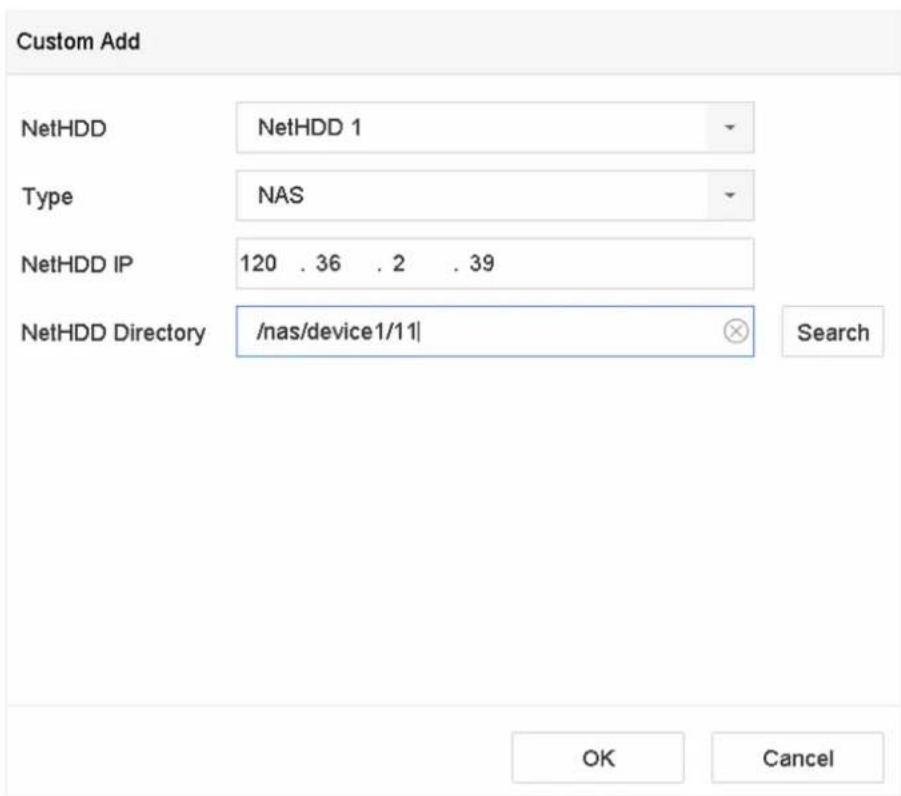
Figure 8-3 Add NetHDD
- Select NetHDD type.
- Enter NetHDD IP address and click Search to search the available NetHDD.
- Select the desired NetHDD.
- Click OK.
- The added NetHDD will be displayed in the HDD list. Select the newly added NetHDD and click Init.
8.1.4 Manage eSATA
Configure eSATA for Data Storage
When there is an external eSATA device connected to your video recorder, you can configure the eSATA usage as data storage and manage the eSATA.
Steps
- Go to Storage → Advanced.
- Select eSATA Usage as Export or Record/Capture.
Export
Use the eSATA for backup.
Record/Capture
Use the eSATA for record/capture. Refer to the following steps for operating instructions.
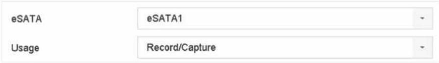
Figure 8-4 eSATA Mode
What to do next
If eSATA usage is set as Record/Capture, enter the storage device interface to edit its property or initialize it.
Configure eSATA for Auto Backup
If you made an automatic backup plan, the video recorder will back up the local videos of 24 hours ahead of the backup start time to eSATA.
Before You Start
Ensure the device has correctly connected with an external eSATA hard drive, and its usage type is set as Export. Refer to Manage eSATA for details.
Steps
- Go to Storage → Auto Backup.
- Check Auto Backup.
- Set the backup start time in Start Backup at.

If the day experiences a failed backup, the video recorder will back up the videos 48 hours ahead of the backup start time in the next day.
- Select channels for backup.
- Select Backup Stream Type as your desire.
-
Select Overwrite type.
-
Disable: When HDD is full, it will stop writing.
-
Enable: When HDD is full, it will continue to write new files by deleting the oldest files.
-
Click Apply.
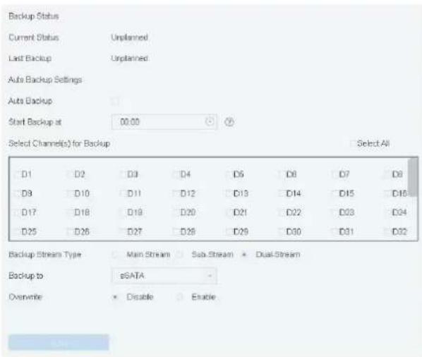
Figure 8-5 Configure eSATA for Auto Backup
8.2 Disk Array
A disk array is a data storage virtualization technology that combines multiple physical disk drives into a single logical unit. Also known as a "RAID", an array stores data over multiple HDDs to provide enough redundancy so that data can be recovered if one disk fails. Data is distributed across the drives in one of several ways called "RAID levels", based the redundancy and performance required.
8.2.1 Create a Disk Array
The video recorder supports software-based disk arrays. Enable the RAID function as required. Two ways are available for creating an array: one-touch configuration and manual configuration.
One-Touch Creation
One-touch configuration creates the disk array. By default, the array type created by one-touch configuration is RAID 5.
Before You Start
Install at least 3 HDDs. If more than 10 HDDs are installed, 2 arrays will be created. To maintain reliability and stability running of the HDDs, it is recommended to use of enterprise-level HDDs of the same model and capacity.
Steps
- Go to Storage → Advanced.
- Check Enable RAID.
-
Click Apply and reboot the device to have settings take effect.
-
After reboot, go to Storage → RAID Setup → Physical Disk.
- Click One-touch Config.
- Edit Array Name and click OK to start configuring.

If you install 4 or more HDDs, a hot spare disk for array rebuilding will be created.
- Optional: The video recorder will automatically initialize the created array. Go to Storage → RAID Setup → Array to view the information of the created array.
Manual Creation
Manually create a RAID 0, RAID 1, RAID 5, RAID 6, or RAID 10 array.
Steps
- Go to Storage → Advanced.
- Check Enable RAID.
- Click Apply and reboot the device to have settings take effect.
- After reboot, go to Storage → RAID Setup → Physical Disk.
- Click Create.
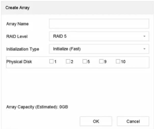
Figure 8-6 Create Array
- Enter Array Name.
- Select RAID Level as required.
- Select the physical disks to constitute the array.
Table 8-1 The Required Number of HDDs
| RAID Level The Required Number of HDDs | |
| RAID 0 At least 2 HDDs. | |
| RAID 1 At least 2 HDDs. | |
| RAID 5 At least 3 HDDs. | |
| RAID 6 At least 4 HDDs. | |
| RAID 10 The number of HDD must be an even ranges from 4 to 16. | |
9. Click OK.
- Optional: The video recorder will automatically initialize the created array. Go to Storage → RAID Setup → Array to view the information of the created array.
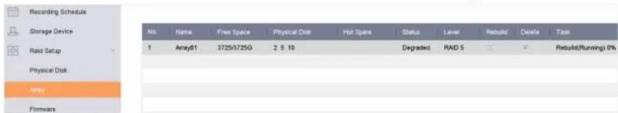
Figure 8-7 Array List
8.2.2 Rebuild an Array
The array status includes Functional, Degraded, and Offline. To ensure the high security and reliability of the data stored in an array, take immediate and proper maintenance of the arrays according its status.
Functional
No disk loss in the array.
Offline
The number of lost disks has exceeded the limit.
Degraded
If any HDD fails in the array, the array degrades. Restore it to Functional status by rebuilding the array.
Configure a Hot Spare Disk
The hot spare disk is required for the disk array automatic rebuilding.
Steps
- Go to Storage → RAID Setup → Physical Disk.
| No. | Capacity | Array | Type | Status | Model | Hof Spare | Task |
| 1 | 1863.02GB | Array01 | Array | Functional | ST2000VX000-1CU164 | None | |
| 2 | 2794.52GB | Normal | Functional | ST3000VX000-9YW166 | None | ||
| 5 | 1863.02GB | Array01 | Array | Functional | ST2000VX000-1CU164 | None | |
| 9 | 2794.52GB | Normal | Functional | ST3000VX000-1CU166 | None | ||
| 10 | 1863.02GB | Array01 | Array | Functional | ST2000VX000-1CU164 | None |
Figure 8-8 Physical Disk
- Click ☑ of an available HDD to set it as the hot spare disk.
Automatically Rebuild an Array
The video recorder can automatically rebuild degraded arrays with the hot spare disks.
Before You Start
Create hot spare disks. For details, refer to Configure a Hot Spare Disk.
Steps
- Go to Storage → RAID Setup → Array.
| Recording Schedule | ||||||||
| Storage Device | ||||||||
| Raid Setup | 1 | Array01 | 3725/3725G | 2 5 10 | Degraded | RAID 5 | X | Rebuild(Running) 0% |
| Physical Disk | ||||||||
| Array | ||||||||
| Firmware | ||||||||
Figure 8-9 Array List
Manually Rebuild an Array
If no hot spare disks are configured, rebuild a degraded array manually.
Before You Start
At least one available physical disk must exist to rebuild an array.
Steps
- Go to Storage → RAID Setup → Array.
- Click ☑ of the degraded array.
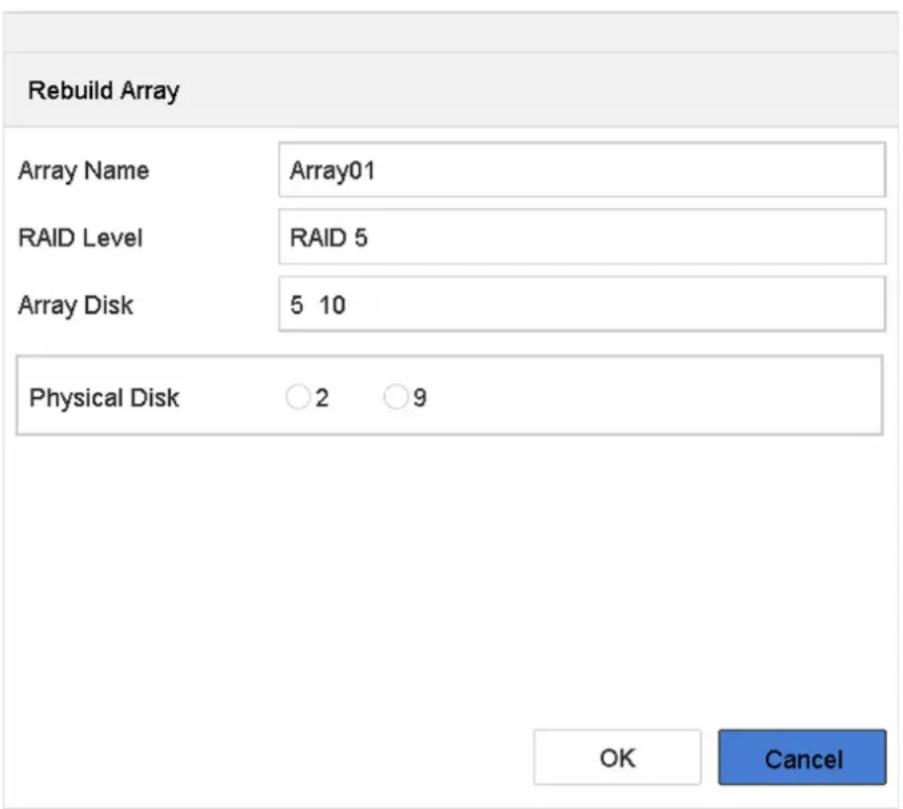
Figure 8-10 Rebuild Array
- Select the available physical disk.
- Click OK.
- Click OK on the pop up message box "Do not unplug the physical disk when it is under rebuilding."
Chapter 9 POS Configuration
The device can be connected to a POS machine/server, and receive a transaction message to overlay on the image during Live View or playback, as well as trigger a POS event alarm.
9.1 Configure POS Connection
Steps
- Go to System → POS.
- Click Add.
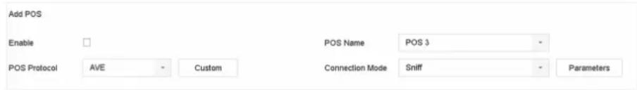
Figure 9-1 POS Settings
- Select a POS device from the drop-down list.
- Check Enable.

The number of POS devices supported by each device is the half of its number of channel, e.g., 8 POS devices are supported for the DS-9616NI-I8 model.
- Select POS Protocol.

When a new protocol is selected, reboot the device to activate the new settings.
Universal Protocol
Click Advanced to expand more settings when selecting the universal protocol. You can set the start line identifier, line break tag, and end line tag for the POS overlay characters, and the case-sensitive property of the characters. You can also optionally check the filtering identifier and the XML protocol.
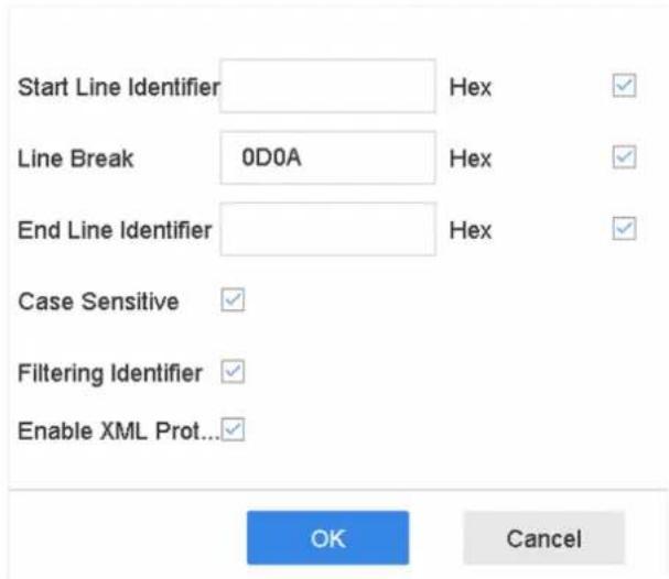
Figure 9-2 Universal Protocol Settings
EPSON
The fixed start and end line tag are used for EPSON protocol.
AVE
The fixed start and end line tag are used for AVE protocol. Serial port and virtual serial port connection types are supported.
Click Custom to configure the AVE settings. Select Rule as VSI-ADD or VNET. Set the address bit of the POS message to send. Click OK to save the settings.
NUCLEUS
Click the Custom to configure the NUCLEUS settings.
Enter the employee No., shift No., and the terminal No. in the field. The matching message sent from the POS device will be used as the valid POS data.

The NUCLEUS protocol must be used in the RS-232 connection communication.
- Select Connection Mode and click Parameters to configure the parameters for each connection mode.
TCP Connection
When using TCP connection, the port must be set from 1 to 65535, and the port for each POS machine must be unique.
Set the Allowed Remote IP Address of the device sending the POS message.
UDP Connection
When using UDP connection, the port must be set from 1 to 65535, and the port for each POS machine must be unique.
Set the Allowed Remote IP Address of the device sending the POS message.
USB-to-RS-232 Connection
Configure the USB-to-RS-232 convertor port parameters, including the port serial number, baud rate, data bit, stop bit, parity, and flow ctrl.
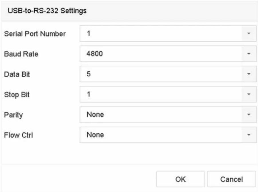
Figure 9-3 USB-to-RS-232 Settings
RS-232 Connection
Connect the device and the POS machine via RS-232. The RS-232 settings can be configured in Menu → Configuration → RS-232. The Usage must be set to Transparent Channel.
Multicast Connection
When connecting the device and the POS machine via Multicast protocol, set the multicast address and port.
Sniff Connection
Connect the device and the POS machine via Sniff. Configure the source address and destination address settings.
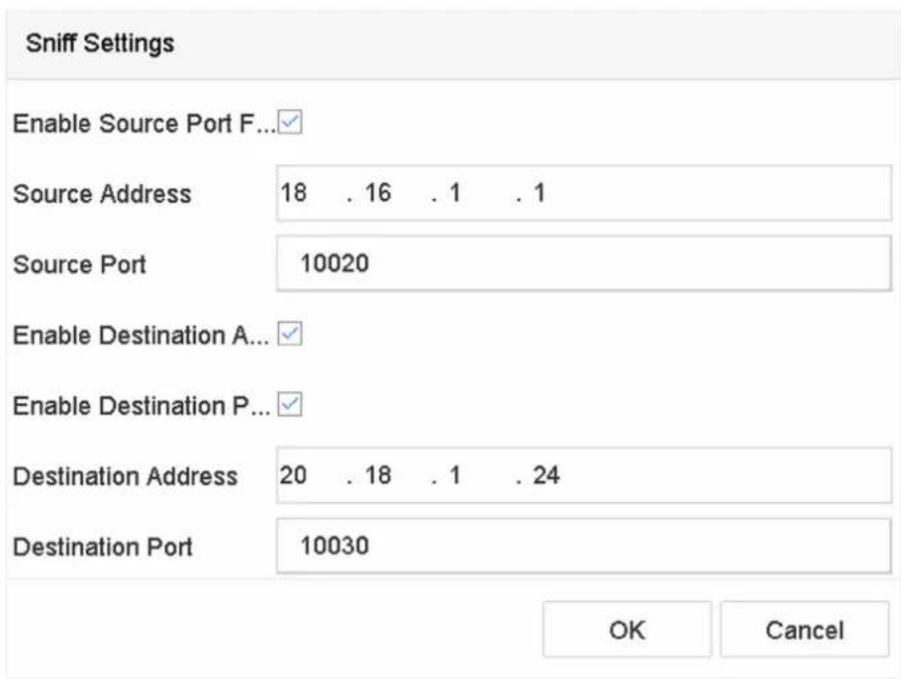
Figure 9-4 Sniff Settings
9.2 Configure POS Text Overlay
Steps
- Go to System → POS.
- Click Channel Linkage and Display.
![Channel Linkage and Display Arming Schedule Event Linkage Linked Channel [D1] IPCamera 02 Character Encod... UTF-8 Overlay Mode Page Font Size Large Medium Small Font Color Display for(s) 30 Timeout(s) 5 Privacy Settings 1634 0921 543 For example, the entered card number will be shown ... Overlay POS in ...](/content/2026/06/1194368/images/9bdc0b0d394ff001bd8196ffd8fb895e15881a03f5999d1066fb5921519576e4.jpg)
Figure 9-5 Overlay Character Settings
- Select linked channel to overlay the POS characters.
-
Set the characters overlay for the enabled POS.
-
Character encoding format: currently the Latin-1 format is available
• Overlay mode of the characters to display in scrolling or page mod -
Font size and font color
- Display time (sec) of the characters. The value ranges 5 -3600 sec.
-
Timeout of POS event. The value ranges 5 -3600 sec. When the device has not received the POS message within the defined time, the transaction ends.
-
In Privacy Settings, set the POS privacy information to not display on the image, e.g., the card number, user name, etc.
The defined privacy information will be displayed using ***on the image instead.
- Check Overlay POS in Live View. When this feature is enabled, the POS information is overlaid on the Live View image.

Drag the frame to adjust the textbox size and position on POS settings interface preview screen.
- Click Apply to activate the settings.
9.3 Configure POS Alarm
A POS event can trigger channels to start recording, or trigger full screen monitoring or an audio warning, notifying the surveillance center, send e-mail, etc.
Steps
- Go to Storage → Recording Schedule.
- Set the POS event's arming schedule.
- Go to System → POS.
- Click Event Linkage on the POS adding or editing interface.
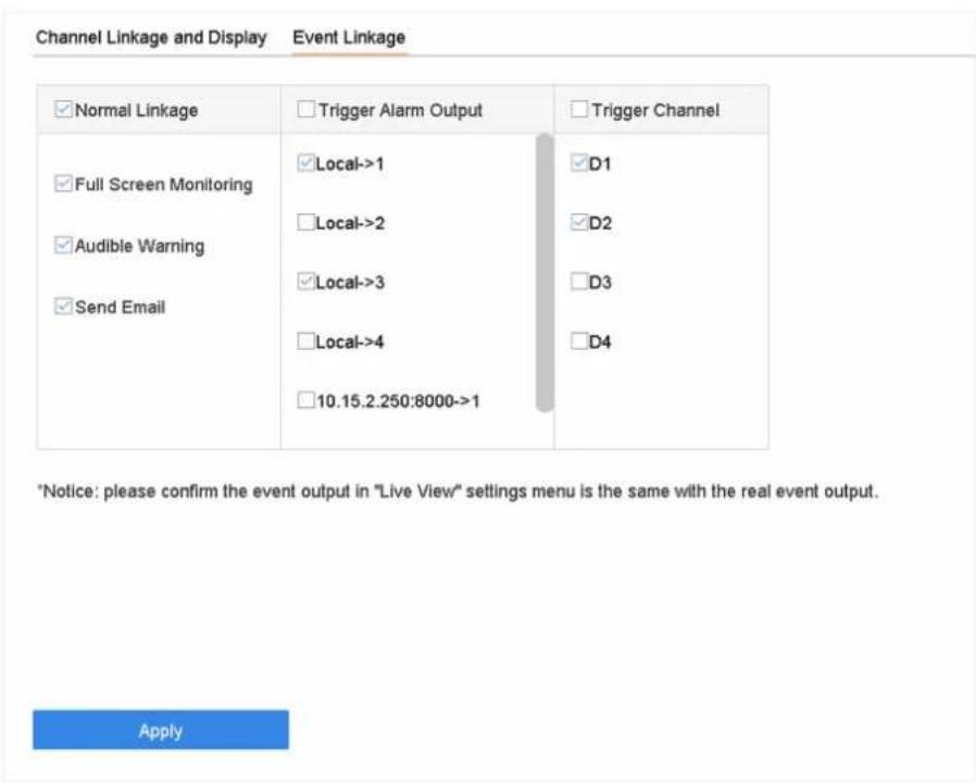
Figure 9-6 Set Trigger Cameras of POS
- Select the normal linkage actions.
- Select one or more alarm output(s) to trigger.
- Select one or more channels to record or become full-screen monitoring when a POS alarm is triggered.
- Click Apply to save the settings.
Chapter 10 Hot Spare Recorder Backup
Video recorders can form an N+1 hot spare system. The system consists of several working video recorders and a hot spare video recorder; when the working video recorder fails, the hot spare video recorder switches into operation, thus increasing the reliability of the system. Contact your dealer for details of models that support the hot spare function.
A bidirectional connection shown in the figure below is required to be built between the hot spare video recorder and each working video recorder.

Figure 10-1 Building a Hot Spare System
Hot spare devices takes over working device tasks when working device fails.
Steps
- Go to System → Hot Spare.
- Select Work Mode as Hot Spare Mode.
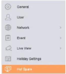
Work Mode

Figure 10-2 Hot Spare
3. Click Apply.
- Click Yes in the pop-up attention box to reboot the device.

Note
- The camera connection will be disabled when the device works in hot spare mode.
- It is highly recommended to restore the device defaults after switching the working mode of the hot spare device to normal mode to ensure the normal operation afterward.
10.2 Set Working Recorder
Steps
- Go to System → Hot Spare.
- Select Work Mode as Normal Mode.
- Check Enable.
- Enter IP address, user name, and admin password of the hot spare recorder.
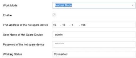
*Notice: After the hot spare is enabled, you must link the working device to the hot spare device, otherwise, this function is not available.
Figure 10-3 Hot Spare
- Click Apply.
10.3 Manage Hot Spare System
Steps
- Go to System → Hot Spare in the hot spare recorder.
- Check working recorders on the device list and click Add to link the working recorder to the hot spare recorder. The working recorder working statusdescriptions are as follows:
No record
The working recorder works properly.
Backing up
If the working recorder goes offline, the hot spare recorder will record the videos of the network camera connected to the working device. The video back up functions for one working recorder at a time.
Synchronizing
When the working recorder comes back online, the lost videos will be restored by the video synchronization function. The video synchronization function can be enabled for one working recorder at a time.

Note
A hot spare recorder can connect up to 32 working recorders.
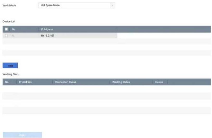
Figure 10-4 Add Working Recorder
Chapter 11 Network Settings
11.1 Configure DDNS
You can set Dynamic DNS service for network access. Different DDNS modes are available: DynDNS, PeanutHull, and NO-IP.
Before You Start
You must register the DynDNS, PeanutHull, or NO-IP services with your ISP before configuring DDNS settings.
Steps
- Go to System → Network → TCP/IP → DDNS
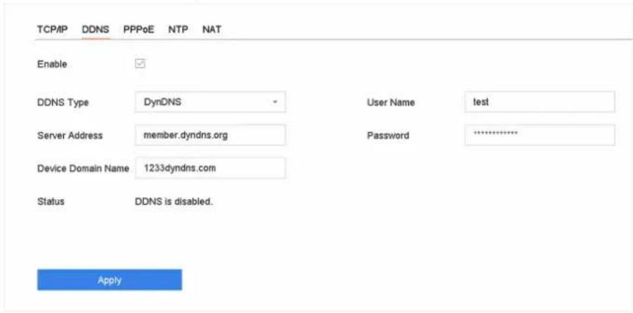
Figure 11-1 DDNS Settings
- Check Enable.
- Select DDNS Type as DynDNS.
- Enter Server Address for DynDNS (i.e., members.dyndns.org).
- Under Device Domain Name, enter the domain name obtained from the DynDNS Website.
- Enter User Name and Password registered in the DynDNS Website.
- Click Apply.
11.2 17.3 Configure PPPoE
If the device is connected to Internet through PPPoE, you need to configure user name and password accordingly under System → Network → TCP/IP → PPPoE.
Contact your Internet service provider for details about PPPoE service.
11.3 Configure Port Mapping (NAT)
Two ways are provided for port mapping to realize the remote access via the cross-segment network, UPnP™ and manual mapping.
Before You Start
If you want to enable the UPnP™ function of the device, you must enable the UPnP™ function of the router to which your device is connected. When the network working mode of the device is set as multi-address, the Default Route of the device should be in the same network segment as that of the LAN IP address of the router.
Universal Plug and Play (UPnP™) can permit the device seamlessly discover the presence of other network devices on the network and establish functional network services for data sharing, communications, etc. You can use the UPnP™ function to enable the fast connection of the device to the WAN via a router without port mapping.
Steps
- Go to System → Network → TCP/IP → NAT.
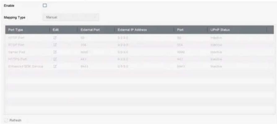
Figure 11-2 Port Mapping Setting
2. Check Enable.
-
Select Mapping Type as Manual or Auto.
-
Auto: If you select Auto, the port mapping items are read-only, and the external ports are set by the router automatically.
- Manual: If you select Manual, you can edit the external port on your demand by clicking to activate External Port Settings.

Note
- You can use the default port No., or change it according to actual requirements.
- External Port indicates the port No. for port mapping in the router.
- The value of the RTSP port No. should be 554 or between 1024 and 65535, while the value of the other ports should be between 1 and 65535 and the value must be different from each
other. If multiple devices are configured for the UPnP™ settings under the same router, the value of the port No. for each device should be unique.
- Enter the virtual server setting page of router; fill in the blank of Internal Source Port with the internal port value, the blank of External Source Port with the external port value, and other required contents.

Note
• Each item should be corresponding with the device port, including server port, http port, RTSP port and https port.
- The virtual server setting interface below is for reference only, it may be different due to different router manufactures. Please contact the manufacture of router if you have any problems with setting virtual server.
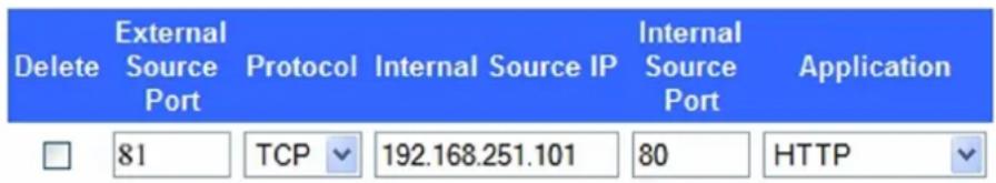
Figure 11-3 Setting Virtual Server Item
11.4 Configure SNMP
You can configure SNMP settings to get device status and parameter information.
Before You Start
Download the SNMP software to receive device information via the SNMP port. By setting the trap address and port, the device is allowed to send alarm events and exception messages to the surveillance center.
Steps
- Go to System → Network → Advanced → SNMP.
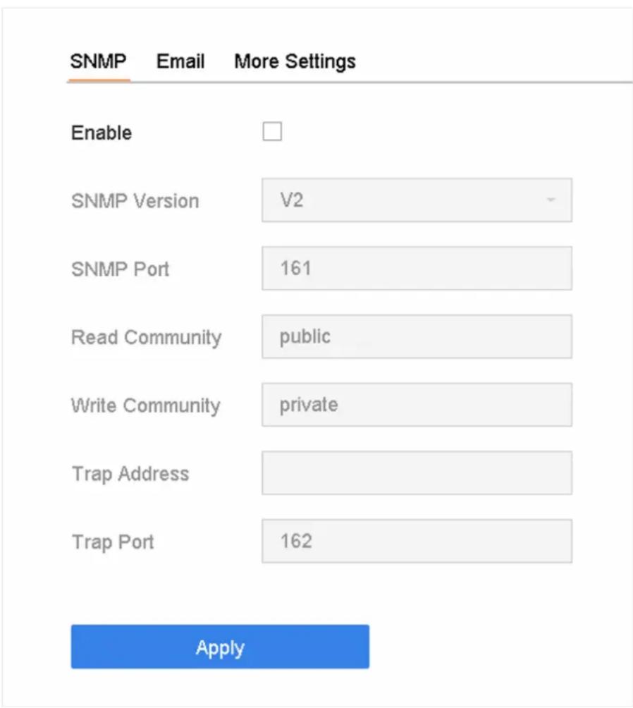
Figure 11-4 SNMP Settings
- Check Enable. A message will pop up to notify about a possible security risk. Click Yes to continue.
- Configure the SNMP settings as needed.
Trap Address
SNMP host IP address.
Trap Port
Port of the SNMP host.
- Click Apply.
11.5 Configure Email
The system can be configured to send an e-mail notification to all designated users when a specified event occurs such as when an alarm or motion event is detected, or the administrator password is changed, etc.
Before You Start
The device must be connected to a local area network (LAN) that contains an SMTP mail server. The network must also be connected to either an intranet or the Internet depending on the location of the e-mail accounts to which you want to send notifications.
Steps
- Go to System → Network → Advanced → Email.
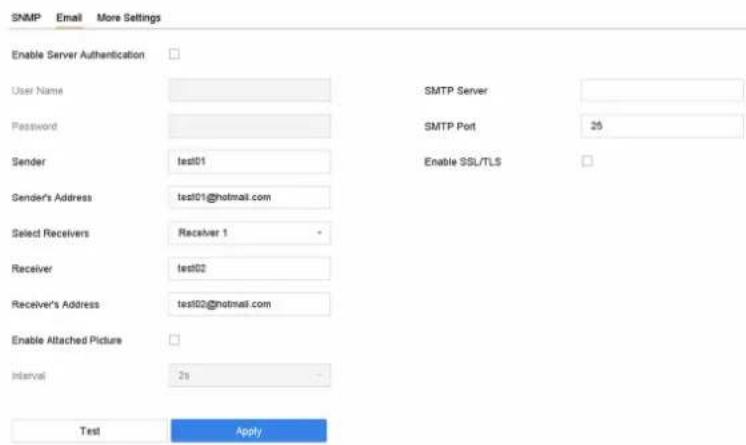
Figure 11-5 Email Settings
- Configure the email settings.
Enable Server Authentication
Check to enable the function if the SMTP server requires user authentication and enter the user name and password accordingly.
SMTP Server
The IP address of SMTP Server or host name (e.g., smtp.263xmail.com).
SMTP Port
The SMTP port. The default TCP/IP port used for SMTP is 25.
Enable SSL/TLS
Check to enable SSL/TLS if required by the SMTP server.
Sender
The sender's name.
Sender's Address
The sender's address.
Select Receivers
Select the receiver. Up to 3 receivers can be configured.
Receiver
The receiver's name.
Receiver's Address
The e-mail address of the user to be notified.
Enable Attached Picture
Check to send e-mail with attached alarm images. The interval is the time between sending two subsequent alarm images.
- Click Apply.
- Optional: Click Test to send a test email.
11.6 Configure Port
You can configure different types of ports to enable relevant functions.
Steps
- Go to System → Network → Advanced → More Settings.
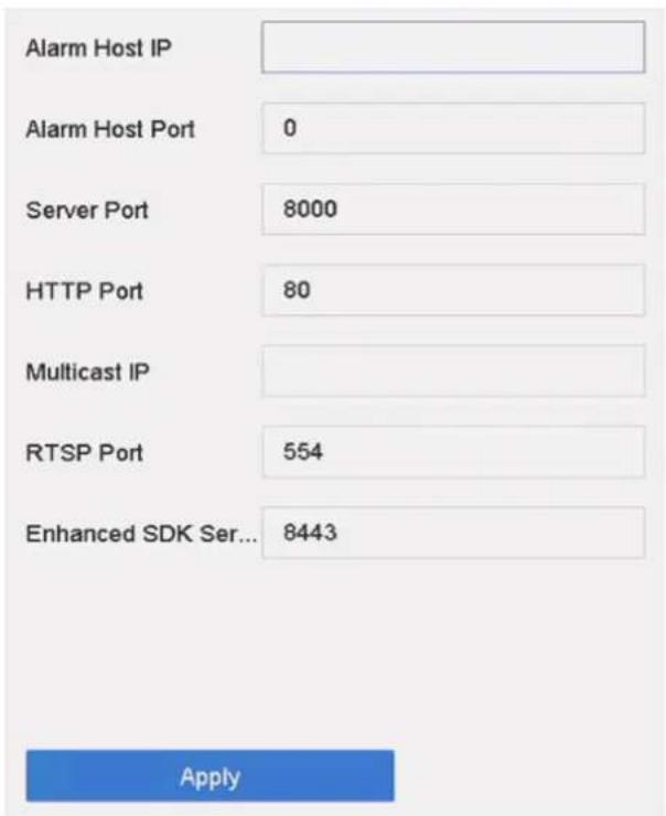
Figure 11-6 Port Settings
- configure port settings as needed.
Alarm Host IP/Port
With a remote alarm host configured, the device will send the alarm event or exception message to the host when an alarm is triggered. The remote alarm host must have the client management system (CMS) software installed. The alarm host IP refers to the IP address of the remote PC on which the CMS software (e.g., iVMS-4200) is installed, and the alarm host port (7200 by default) must be the same as the alarm monitoring port configured in the software.
Server Port
Server port (8000 by default) should be configured for remote client software access and its valid range is 2000 to 65535.
HTTP Port
HTTP port (80 by default) should be configured for remote Web browser access.
Multicast IP
Multicast can be configured to enable Live View for cameras that exceed the maximum number allowed through network. A multicast IP address covers Class-D IP ranging from 224.0.0.0 to 239.255.255.255 and it is recommended to use an IP address ranging from 239.252.0.0 to 239.255.255.255. When adding a device to the CMS software, the multicast address must be the same as that of the device.
RTSP Port
RTSP (Real Time Streaming Protocol) is a network control protocol designed to control streaming media servers. The port is 554 by default.
Enhanced SDK Service Port
The enhanced SDK service adopts TLS protocol over the SDK service that provides safer data transmission. The port is 8443 by default.
3. Click Apply.
11.7 Configure ONVIF
ONVIF protocol allows the connection with third-party cameras. The added user accounts have the permission to connect other devices via ONVIF protocol.
Steps
-
Go to System → System Service → ONVIF.
-
Check Enable ONVIF to enable the ONVIF access management.

Note
ONVIF protocol is disabled by default.
-
Click Add.
-
Enter User Name, and Password

Caution
We highly recommend you create a strong password of your own choosing (Using a minimum of 8 characters, including at least three of the following categories: upper case letters, lower case letters, numbers, and special characters.) in order to increase the security of your product. And we recommend you reset your password regularly, especially in the high security system, resetting the password monthly or weekly can better protect your product.
-
Select Level as Media User, Operator or Admin.
-
Click OK.
Chapter 12 User Management and Security
12.1 Manage User Accounts
The Administrator user name is admin and the password is set when you start the device for the first time. The Administrator has the permission to add and delete users and configure user parameters.
12.1.1 Add a User
Steps
- Go to System → User.
- Click Add to enter the operation permission interface.
- Input the admin password and click OK.
- In the Add User interface, enter the information for a new user.

Caution
Strong Password Recommended—We highly recommend you create a strong password of your own choosing (using a minimum of 8 characters, including at least three of the following categories: upper case letters, lower case letters, numbers, and special characters) in order to increase the security of your product. We also recommend that you reset your password regularly. Especially in the high security systems, resetting the password monthly or weekly can better protect your product.
User Level
Set the user level to Operator or Guest. Different user levels have different operating permission.
- Operator: An Operator user level has Two-way Audio permission in Remote Configuration and all operating permissions in Camera Configuration by default.
- Guest: The Guest user has no permission of Two-way Audio in Remote Configuration and only has the local/remote playback in the Camera Configuration by default.
User's MAC Address
The MAC address of the remote PC that logs onto the device. If it is configured and enabled, it allows only the remote user with this MAC address to access the device.
5. Click OK.
In the User Management interface, the added new user is displayed on the list.
12.1.2 Edit the Admin User
For the admin user account, you can modify your password and unlock pattern.
Steps
- Go to System → User.
- Select the admin user from the list.
- Click Modify.
![Edit User User Name admin Password ********* Discard C... Confirm ********* Note: Valid password range [8-16]. You can use... Password S... User's MAC Ad... 00 : 00 : 00 : 00 : 00 : 0C Unlock Patt... Enable Unlock Pattern GUID File Export ? Security Qu... Reserved E... Modify OK Cancel](/content/2026/06/1194368/images/fc475108215c06eed7aabdecc52d5c36e7da274e154d5b268b61182f9fa46311.jpg)
Figure 12-1 Edit User (Admin)
- Edit the admin user information as desired, including a new admin password (strong password is required) and MAC address.
- Edit the unlock pattern for the admin user account.
1) Check Enable Unlock Pattern to enable the use of an unlock pattern when logging in to the device.
2) Use the mouse to draw a pattern among the 9 dots on the screen, and release the mouse when the pattern is done.
- Check Export of GUID File to export the GUID file for the admin user account.

Note
When the admin password is changed, export the new GUID to the connected USB flash drive in the Import/Export interface for the future password resetting.
- Configure security question for password resetting.
-
Configure reserved email for password resetting.
-
Click OK to save the settings.
12.1.3 Edit an Operator/Guest User
You can edit the user information, including user name, password, permission level, and MAC address.
Steps
-
Go to System → User.
-
Select a user from the list and click Modify.
![Edit User User Name A01 Password ******** Confirm ******** Note:Valid password range [8-16]. You can use ... Password Stre... User Level Operator User's MAC Ad... 00 : 00 : 00 : 00 : 00 : 00 Discard C... OK](/content/2026/06/1194368/images/900d401572b6e3aa38d41f30a08218d595494f018beba481f539a853ff455054.jpg)
Figure 12-2 Edit User (Operator/Guest)
-
Edit the user information as desired, including the new password (strong password is required) and MAC address.
-
Click OK.
12.2 Manage User Permissions
12.2.1 Set User Permissions
For an added user, you can assign the different permissions, including local and remote operation of the device.
Steps
-
Go to System → User.
-
Select a user from the list, and then click √ to enter the permission settings interface.
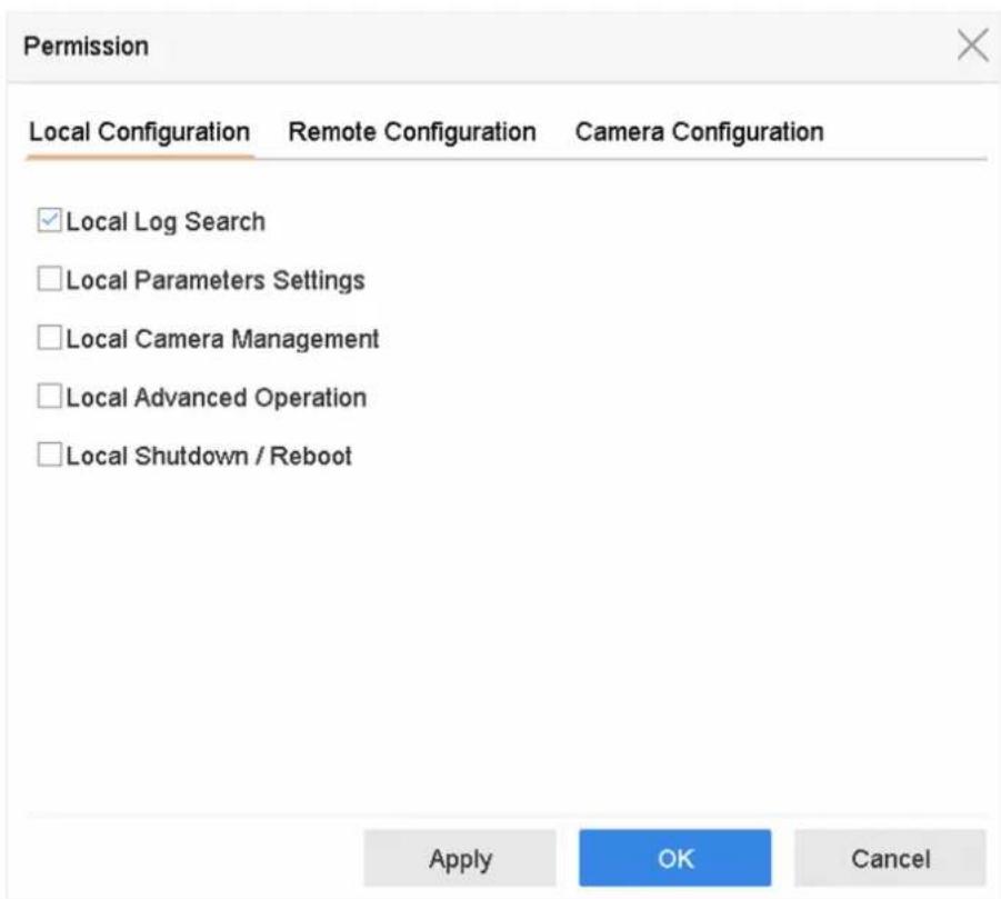
Figure 12-3 User Permission Settings Interface
- Set the user's operating permissions for Local Configuration, Remote Configuration, and Camera Configuration for the user.
1) Set Local Configuration
Local Log Search
Searching and viewing logs and system information of device.
Local Parameters Settings
Configuring parameters, restoring factory default parameters, and importing/exporting configuration files.
Local Camera Management
Adding, deleting, and editing of IP cameras.
Local Advanced Operation
Operating HDD management (initializing HDD, setting HDD property), upgrading system firmware, clearing I/O alarm output.
Local Shutdown Reboot
Shutting down or rebooting the device.
2) Set Remote Configuration
Remote Log Search
Remotely viewing logs that are saved on the device.
Remote Parameters Settings
Remotely configuring parameters, restoring factory default parameters, and importing/exporting configuration files.
Remote Camera Management
Remote adding, deleting, and editing of the IP cameras.
Remote Serial Port Control
Configuring settings for RS-232 and RS-485 port settings.
Remote Video Output Control
Sending remote button control signals.
Two-Way Audio
Operating the two-way radio between the remote client and the device.
Remote Alarm Control
Remotely arming (notify alarm and exception message to the remote client) and controlling the alarm output.
Remote Advanced Operation
Remotely operating HDD management (initializing HDD, setting HDD property), upgrading system firmware, clearing I/O alarm output.
Remote Shutdown/Reboot
Remotely shutting down or rebooting the device.
3) Set Camera Configuration
Remote Live View
Remotely viewing live video of the selected camera(s).
Local Manual Operation
Locally starting/stopping manual recording and alarm output of the selected camera(s).
Remote Manual Operation
Remotely starting/stopping manual recording and alarm output of the selected camera(s).
Local Playback
Locally playing back recorded files of the selected camera(s).
Remote Playback
Remotely playing back recorded files of the selected camera(s).
Local PTZ Control
Locally controlling PTZ movement of the selected camera(s).
Remote PTZ Control
Remotely controlling PTZ movement of the selected camera(s).
Local Video Export
Locally exporting recorded files of the selected camera(s).
Local Live View
View live video of the selected camera(s) in local.
- Click OK to save the settings.
12.2.2 Set Live View Permission on Lock Screen
The admin user can set live view permission for specific cameras in the screen lock status of device.
- The admin user can set this permission for user accounts.
- When the normal user (Operator or Guest) has no local live view permission for specific camera (s), the live view permission for such camera (s) on lock screen status cannot be configured (live view not allowed by default).
Steps
- Go to System → User.
- Click Live View Permission on Lock Screen.
- Input admin password and click Next.
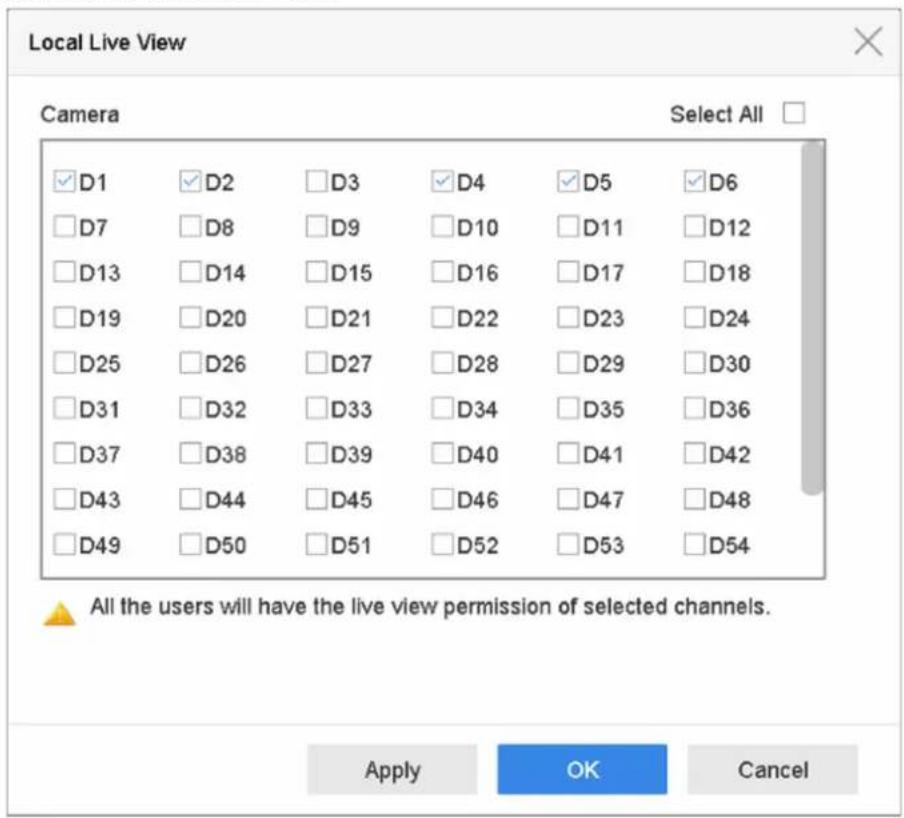
Figure 12-4 Set Live View Permissions on Lock Screen
- Set the permissions.Select the camera (s) to allow live view when the current user account is in logout status.
- Click OK.
12.3 Configure Password Security
12.3.1 Export GUID File
The GUID file can help you to reset password when you forget it. You can export GUID file via web browser. Please keep the GUID file properly.
Before You Start
Ensure you are on the same network segment with your device.
Steps
- Go to Configuration → System → User Management → User Management.
- Select the admin user.
- Click Account Security Settings.
- Click Modify.
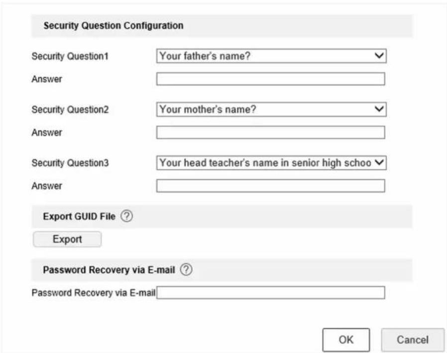
Figure 12-5 Export GUID File
- Click Export in Export GUID File.
- Enter the admin password.
- Save the GUID file to a directory as your desire.
12.3.2 Configure Security Questions
The security questions can help you to reset password when you forget your password, or encounter security issues.
Steps
-
Click Security Question Configuration when you are activating the device, or editing the admin user account.
-
Select three security questions from the drop-down list and input the answers.
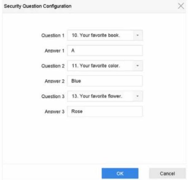
Figure 12-6 Configure Security Questions
- Click OK.
12.3.3 Configure Reserved Email
The reserved email will help you to reset password when you forget your password.
Steps
- Check Reserved E-mail when you are activating the device, or click Modify when you are editing the admin user account.
- Enter reserved email address.
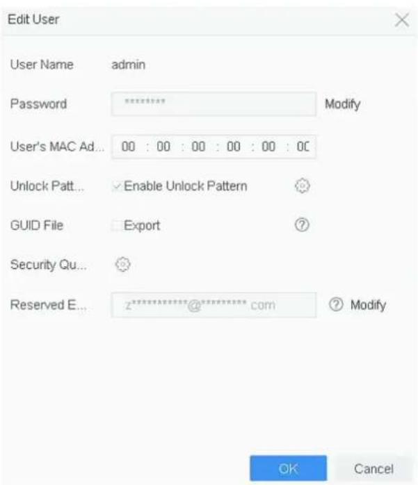
Figure 12-7 Configure Reserved Email
- Click OK.
12.4 Reset Password
When you forget the admin password, you can reset the password by importing the GUID file, answering security questions, or entering verification code from your reserved email.
12.4.1 Reset Password by GUID
You can reset password by GUID via web browser.
Before You Start
Ensure you have the correct GUID file.
Steps
- On the user login interface, click Forgot password?
- Select Verification Mode as GUID File Verification.
- Click Browse to locate the GUID file.
- Click Next.
- Enter a new password.
Warning
We highly recommend you to create a strong password of your own choosing (using a minimum of 8 characters, including at least three kinds of following categories: upper case letters, lower case letters, numbers, and special characters) in order to increase the security of your product. And we recommend you change your password regularly, especially in the high security system, changing the password monthly or weekly can better protect your product.
- Confirm the new password.
- Click Next.
12.4.2 Reset Password by Security Questions
You can reset password by security questions via web browser.
Before You Start
Ensure you have configured the security questions when you activate the device or edit the admin user account.
Steps
- On the user login interface, click Forgot password?
- Select Verification Mode as Security Question Verification.
- Enter the answers of each question.
- Click Next.
- Enter the new password twice.
Warning
We highly recommend you to create a strong password of your own choosing (using a minimum of 8 characters, including at least three kinds of following categories: upper case letters, lower case letters, numbers, and special characters) in order to increase the security of your product. And we recommend you change your password regularly, especially in the high security system, changing the password monthly or weekly can better protect your product.
6. Click Next.
12.4.3 Reset Password by Reserved Email
Before You Start
Ensure you have configured the reserved email when you are activating the device or editing the admin user account. (Refer to Configure Reserved Email)
Steps
- On the user login interface, click Forgot Password.
- On the password reset type interface, Select Verify by Reserved Email.
-
Click OK.
-
Click Next if you accept the legal disclaimer. You can use a smartphone to scan the QR code and read the legal disclaimer.
-
Obtain the verification code. There are two ways to get the verification code.
-
Use Guarding Vision app to scan the QR code.
- Send the QR code to email server.
a. Insert a USB flash drive to your device.
b. Click Export to export the QR code to USB flash drive.
c. Email the QR code to pw_recovery@device-service.com as attachment.
-
Check your reserved email, and you will receive a verification code within 5 minutes.
-
Enter the verification code.
- Click OK to set the new password.
12.4.4 Reset Password by Guarding Vision
It will restore all parameters to factory default settings if you reset password by Guarding Vision.
Before You Start
Install the Guarding Vision app on your smart phone.
Steps
- On the user login interface, click Forgot Password.
- On the password reset type interface, select Verify by Guarding Vision.
- Use Guarding Vision to scan the QR code. Thereafter, you will have a verification code from Guarding Vision.
- Enter the verification code.
- Click OK.
Chapter 13 System Management
13.1 Configure Device
Steps
-
Go to System → General.
-
Configure the following settings.
Language
The default language used is English.
Output Standard
Set the output standard to NTSC or PAL, which must be the same as the video input standard.
Resolution
Configure video output resolution.
Device Name
Edit device name.
Device No.
Edit the device serial number. The Device No. can be set in the range of 1 to 255, and the default No. is 255. The number is used for the remote and keyboard control.
Auto Logout
Set the timeout time for menu inactivity. E.g., when the timeout time is set to 5 minutes, then the system will exit from the current operation menu to Live View screen after 5 minutes of menu inactivity.
Mouse Pointer Speed
Set the speed of the mouse pointer; 4 levels are configurable.
Enable Wizard
Enable/disable the Wizard when the device starts up.
Enable Password
Enable/disable the use of the login password.
- Click Apply to save the settings.
13.2 Configure Time
13.2.1 Manual Time Synchronization
Steps
- Go to System → General.
- Configure the date and time.
- Click Apply to save the settings.
13.2.2 NTP Synchronization
Connection to a network time protocol (NTP) server can be configured on your device to ensure the system's date and time accuracy.
Steps
- Go to System → Network → TCP/IP → NTP.
- Check Enable.
- Configure NTP settings as need.
Interval (min)
Time interval between two time synchronization with NTP server
NTP Server
IP address of the NTP server
NTP Port
Port of the NTP server
- Click Apply
13.2.3 DST Synchronization
DST (daylight saving time) refers to the period of the year when clocks are moved one period ahead. In some areas worldwide, this has the effect of creating more sunlit hours in the evening during months when the weather is the warmest.
We advance our clocks ahead a certain period (depends on the DST bias you set) at the beginning of DST, and move them back the same period when we return to standardtime (ST).
Steps
- Go to System → General.
- Check Enable DST.
- Set DST mode as Auto or Manual.
Auto
Automatically enable the default DST period according to the local DST rules.
Manual
Manually set the start time and end time of the DST period, and the DST bias.
- Set the DST Bias. Set the time (30/60/90/120 minutes) offset from the standard time.
- Click Apply to save the settings.
13.3 Network Detection
13.3.1 Network Traffic Monitoring
Network traffic monitoring is the process of reviewing, analyzing and managing network traffic for any abnormality or process that can affect network performance, availability and/or security.
Steps
- Go to Maintenance → Network → Traffic.
- You can view the real-time network traffic status, including MTU (Maximum Transmission Unit), and network throughput.
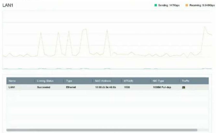
line
| Name | Linking Status | Type | MAC Address | MTUB(B) | NIC Type | Traffic | |------|-----------------|------|-------------|---------|----------|---------| | LAN1 | Succeeded | Ethernet | 18.68cb.9e.46.6b | 1500 | 1000M Full-dup | - |Figure 13-1 Network Traffic
13.3.2 Test Network Delay and Packet Loss
Network delay is caused by slow response of the device when oversized data information is not limited during transmission under certain network protocol, e.g. TCP/IP. Packet loss test is for testing network packet loss rate that is the ratio of lost data packet and total number of transmitted data packet.
Steps
- Go to Maintenance → Network → Network Detection.
-
Select a network card in Select NIC.
-
Enter the destination IP address in Destination Address.
- Click Test.

Figure 13-2 Test Network Delay and Packet Loss
13.3.3 Export Network Packet
After the recorder accessing network, you can use USB flash drive to export network packet.
Before You Start
Prepare a USB flash drive to export network packet.
Steps
- Insert the USB flash drive.
- Go to Maintenance → Network → Network Detection.
-
Select network card in Select NIC.
-
Select the USB flash drive in Device Name. You can click Refresh if the connected local backup device cannot be displayed.

Figure 13-3 Export Network Packet
-
Optional: Click Status to view the network status.
-
Click Export.

Note
It will export 1 MB data each time as default.
13.3.4 Network Resource Statistics
The remote access, including web browser and client software, will consume output bandwidth. You can view the real-time bandwidth statistics.
Steps
- Go to Maintenance → Network → Network Stat.
| Type | bandwidth |
| IP Camera | 5,120Kbps |
| Remote Live View | 0bps |
| Remote Playback | 0bps |
| Net Receive Idle | 155Mbps |
| Net Send Idle | 160Mbps |
Figure 13-4 Network Resource Statistics
- View the bandwidth statistics, including IP Camera, Remote Live View, Remote Play, Net Total Idle, etc.
- Optional: Click Refresh to obtain the latest data.
13.4 Storage Device Maintenance
13.4.1 Bad Sector Detection
Steps
- Go to Maintenance → HDD Operation → Bad Sector Detection.
- Select the HDD No. you want to configure in the dropdown list.
- Select All Detection or Key Area Detection as the detection type.
- Click Self-Test to start the detection.
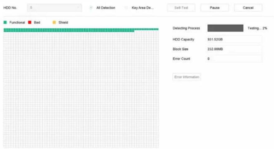
Figure 13-5 Bad Sector Detection

Note
- You can pause/resume or cancel the detection.
- After testing has been completed, you can click Error information to see the detailed damage information.
13.4.2 S.M.A.R.T. Detection
HDD detection functions such as the adopting of the S.M.A.R.T. and the Bad Sector Detection techniques. S.M.A.R.T. (Self-Monitoring, Analysis and Reporting Technology) are HDD monitoring systems to detect various reliability indicators in the hopes of anticipating failures.
Steps
- Go to Maintenance → HDD Operation → S.M.A.R.T.
- Select the HDD to view its S.M.A.R.T. information list.
- Set Self-Test Type.
- Click Self-Test to start the S.M.A.R.T. HDD self-evaluation.
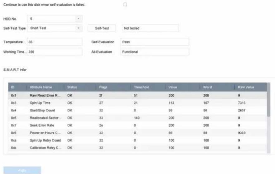
Figure 13-6 S.M.A.R.T. Settings Interface

Note
To use the HDD even when the S.M.A.R.T. checking has failed, check Continue to use the disk when self-evaluation is failed.
The related information of the S.M.A.R.T. is shown, and you can check the HDD status.
13.4.3 HDD Health Detection
You can view the health status of a 4 TB to 8 TB Seagate HDD that generated after October 1, 2017. Use this function to help troubleshoot HDD problems. Health Detection shows a more detailed HDD status than the S.M.A.R.T. function.
Steps
- Go to Maintenance → HDD Operation → Health Detection.
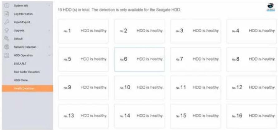
Figure 13-7 Health Detection
- Click a HDD to view details.
13.4.4 Configure Disk Clone
Select the HDDs to clone to the eSATA HDD.
Before You Start
Connect an eSATA disk to the device.
Steps
- Go to Maintenance → HDD Operation → HDD Clone.
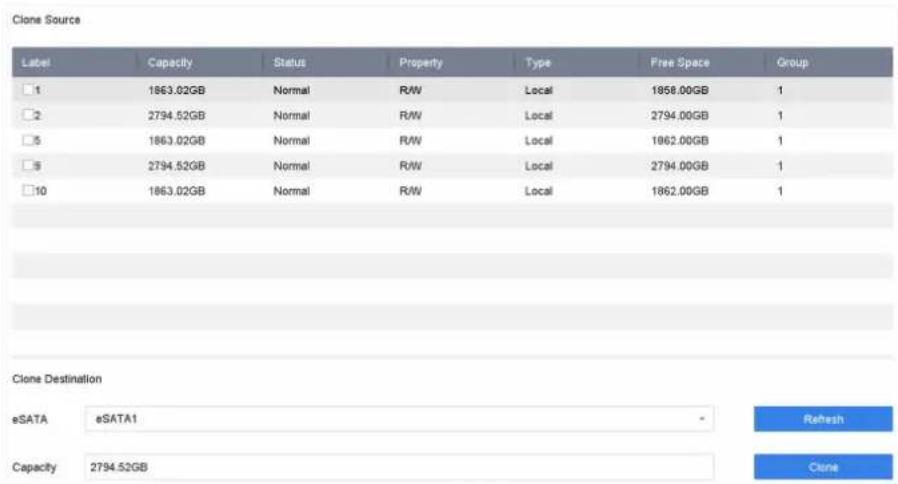
Figure 13-8 HDD Clone
- Check the HDD to clone. The capacity of the selected HDD must match the capacity of the clone destination.
- Click Clone.
- Click Yes on the pop up message box to create the clone.
13.4.5 Repair Database
Repairing database will rebuild all databases. It might help to improve your system speed after upgrade.
Steps
- Go to Storage → Storage Device.
- Select the drive.
- Click Repair Database.
- Click Yes.
i Note
- Repairing database will rebuild all databases. Existing data will not be affected, but local search and playback functions will not be available during the process, you can still achieve search and playback functions remotely via web browser, client software, etc.
- Do not pull out the drive, or shut down the device during the process.
- You can see the repairing progress at Status.
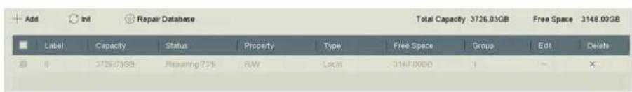
Figure 13-9 Repair Database
13.5 Upgrade Device
Your device firmware can be upgraded with a local backup device or remote FTP server.
13.5.1 Upgrade by Local Backup Device
Before You Start
Connect your device to a local storage device that contains the firmware update file.
Steps
-
Go to Maintenance → Upgrade.
-
Click Local Upgrade to enter the local upgrade interface.
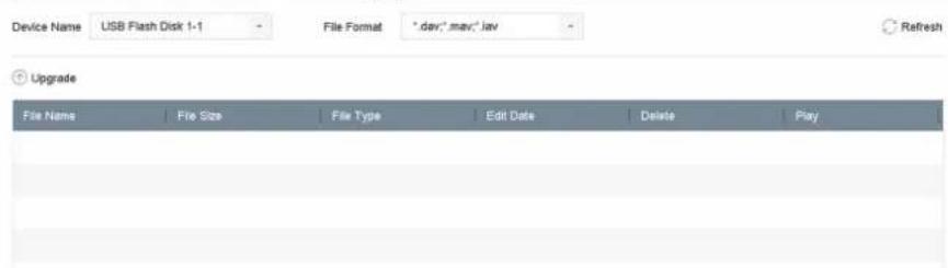
Figure 13-10 Local Upgrade Interface
- Select the firmware update file from the storage device.
- Click Upgrade to start upgrading.
After the upgrade is completed, the device will reboot automatically to activate the new firmware.
13.5.2 Upgrade by FTP
Before You Start
Ensure the network connection of the PC (running FTP server) and the device are valid and correct. Run the FTP server on the PC and copy the firmware into the corresponding directory of your PC.
Steps
- Go to Maintenance → Upgrade.
- Click FTP to enter the local upgrade interface.
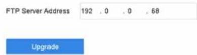
Figure 13-11 FTP Upgrade Interface
- Enter FTP Server Address.
- Click Upgrade to start upgrading.
- After the upgrading is complete, reboot the device to activate the new firmware.
13.5.3 Upgrade by Web Browser
You can upgrade the device by web browser
After logging in to the device via web browser, go to Configuration → System → Maintenance → Upgrade. Click Browse to upload the firmware, and upgrade the device.
13.5.4 Upgrade by Guarding Vision
After logging the device into Guarding Vision, the device would periodically check for the latest firmware from Guarding Vision. If an upgrade firmware is available, the device will notify you when you log in. You can also manually check for the latest firmware.
Before You Start
Ensure the device has successfully connected to Guarding Vision, and it requires to install at least one read-write HDD for firmware downloading.
Steps
-
Go to Maintenance → Upgrade → Online Upgrade.
-
Click Check Upgrade to manually check and download the latest firmware from Guarding Vision.

The device will automatically check for the latest firmware every 24 hours. If it detects available upgrade firmware, the device will notify you when you log in.
- Optional: You can switch on Download Latest Package Automatically to automatically download the latest firmware package.
- Click Upgrade Now.
13.6 Import/Export Device Configuration Files
The device configuration files can be exported to a local device for backup; and the configuration files of one device can be imported to multiple devices if they are to be configured with the same parameters.
Before You Start
Connect a storage device to your device. To import the configuration file, the storage device must contain the file.
Steps
1. Go to Maintenance → Import/Export.
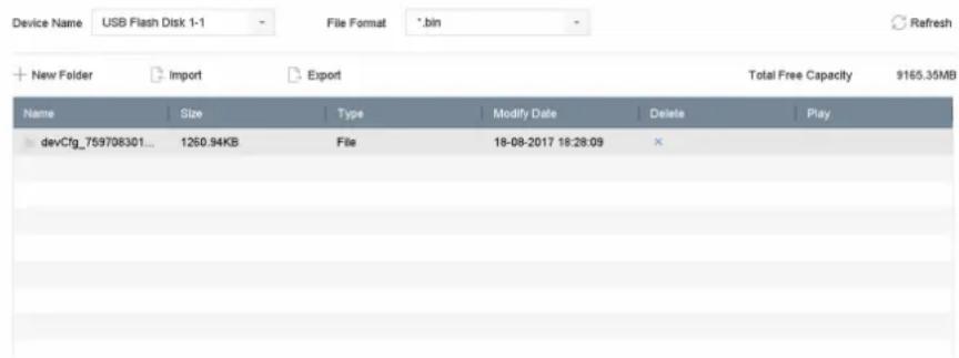
Figure 13-12 Import/Export Config File
2. Export or import the device configuration files.
- Click Export to export configuration files to the selected local backup device.
- To import a configuration file, select the file from the selected backup device and click Import.

After having finished importing configuration files, the device will reboot automatically.
13.7 Log Management
13.7.1 Log Storage
You can customize the log storage disk and log storage period.
Steps
- Go to Storage → Advanced.
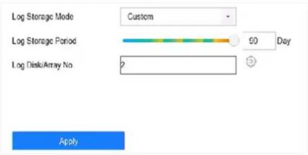
Figure 13-13 Log Storage
2. Set Log Storage Mode.
System Default Each disk will allocate a certain space to store about 400,000 logs. When logs are full, old logs will be overwritten.
Custom You can set Log Storage Period and allocate Log Disk for log storage. When the log disk is full, logs that exceed the period will be overwritten.
3. Click Apply.
13.7.2 Search & Export Log Files
The device operation, alarm, exception, and information can be stored in log files, which can be viewed and exported at any time.
Steps
- Go to Maintenance → Log Information.
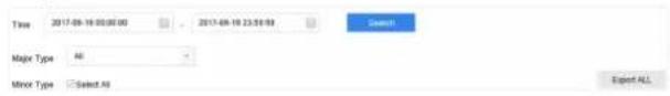
Figure 13-14 Log Search Interface
- Set the log search conditions, including the time, major type and minor type.
- Click Search to start searching the log files.
- The matched log files will be displayed on the list, as shown below.
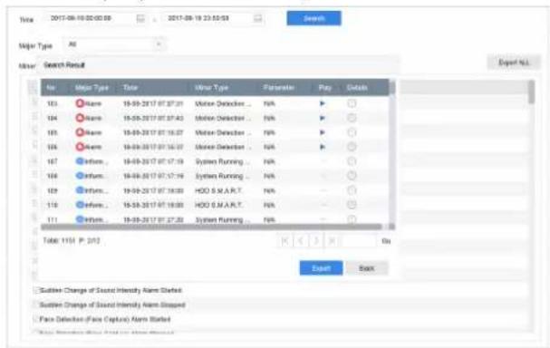
Figure 13-15 Log Search Results

Note
Up to 2,000 log files can be displayed each time.
5. Related Operation:

Click or double-click it to view detailed information.

Click it to view the related video file.
Export/Export ALL Click it to export all the system logs to the storage device.
13.7.3 Upload Logs to the Server
You can upload system logs to the server for backup.
Steps
- Go to System → Network → Advanced → Log Server Settings.
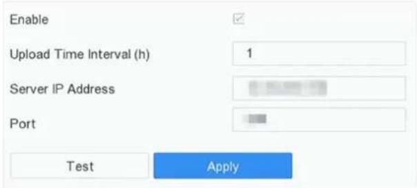
Figure 13-16 Log Server Settings
- Check Enable
- Set Upload Time, Server IP Address, and Port.
- Optional: Click Test to test if parameters are valid.
- Click Apply.
13.7.4 One-Way Authentication
You can install a CA certificate (from the server) to your device to authorize the server via web browser, this would improve the log communication security.
Before You Start
- Download the CA certificate from the server.
- Ensure log server parameters are valid.
Steps
- Go to Configuration → Network → Advanced Settings → Log Server Configuration.
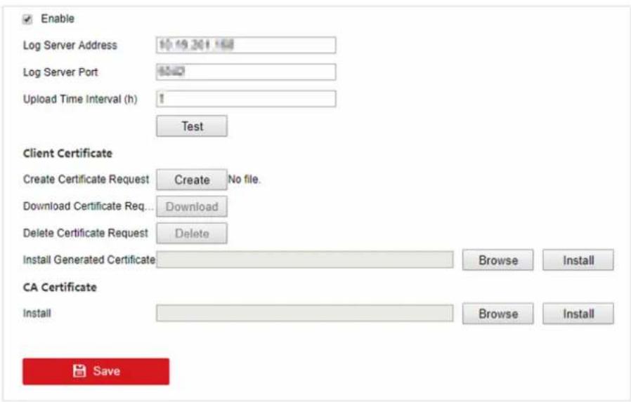
Figure 13-17 One-Way Authentication
- Install the CA certificate in CA Certificate.
- Optional: Click Test to test if the connection is valid.
- Click Save.
13.7.5 Two-Way Authentication
You can install a CA certificate (from the server) to your device to authorize the server, and create a certificate (from your device) to authorize your device by the server. This would improve the log communication security. Two-way authentication can be configured via web browser.
Before You Start
- Download the CA certificate from the server.
- Ensure log server parameters are valid.
Steps
- Go to Configuration → Network → Advanced Settings → Log Server Configuration.

Figure 13-18 Two-Way Authentication
- Install the CA certificate in CA Certificate.
- Click Create in Client Certificate, and follow the pop-up to create the certificate.
- Click Download to download the certificate file to a desired location.
- Upload the downloaded certificate file to the server, and the server will return the certificate key.
- Open the certificate as a text file, and modify it by the certificate key as the server returned.
- Install the modified certificate in Client Certificate.
- Optional: Click Test to test if the connection is valid.
- Click Save.
13.8 Export Diagnostic Information
When exceptions occur, you can export diagnostic information via web browser, and check it.
Steps
-
Go to Configuration → System → Maintenance → Diagnose via web browser.
-
Check Export Diagnostic Information.
-
Click Save.
-
Click Diagnose Information.
-
Set the saving path and file name as your desire.
-
Save the file.
13.9 Restore Default Settings
Steps
- Go to Maintenance → Default.
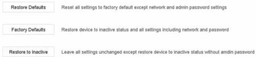
Figure 13-19 Restore Default Settings
- Select the restore type from the following three options.
Restore Defaults
Restore all parameters, except the network (including IP address, subnet mask, gateway, MTU, NIC working mode, default route, server port, etc.) and user account parameters, to the factory default settings.
Factory Defaults
Restore all parameters to the factory default settings.
Restore to Inactive
Restore the recorder to inactive status.

The recorder will reboot automatically after restoring to the default settings.
13.10 Security Management
13.10.1 RTSP Authentication
You can specifically secure the stream data of live view by setting the RTSP authentication.
Steps
- Go to System → System Service → System Service.
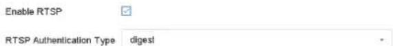
Figure 13-20 RTSP Authentication
- Select RTSP Authentication Type.

Note
Two authentication types are selectable, if you select digest, only the request with digest authentication can access the video stream by the RTSP protocol via the IP address. For security reasons, it is recommended to select digest as the authentication type.
- Click Apply.
- Restart the device to take effect the settings.
13.10.2 ISAPI Service
ISAPI (Internet Server Application Programming Interface) is an open protocol based on HTTP, which can realize the communication between the system devices (e.g., network camera, NVR, etc.). The device is as a server, the system can find and connect the device.
Steps
- Go to System → System Service → System Service.
- Check Enable ISAPI.
- Click Apply.
- Restart the device to take effect the settings.
13.10.3 HTTP Authentication
If you need to enable the HTTP service, you can set HTTP authentication to enhance access security.
Steps
- Go to Maintenance → System Service → System Service.
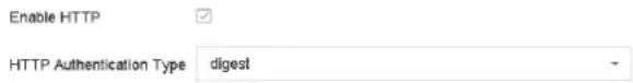
Figure 13-21 HTTP Authentication
- Check Enable HTTP.
- Select HTTP Authentication Type.

Note
Two authentication types are selectable, for security reasons, it is recommended to select digest as the authentication type.
- Click Apply to save the settings.
- Restart the device to take effect the settings.
13.10.4 IP Camera Occupation Detection
After enabling the feature, when search IP camera in Number of Unadded Online Device interface, the status of IP camera the has been added by other device will show as
Steps
- Go to System → System Service → System Service.
- Check Enable IP Camera Occupation Detection.
- Click Apply to save the settings. And reboot device to take effect the settings.
Chapter 14 Appendix
14.1 Glossary
Dual-Stream
Dual-stream is a technology used to record high resolution video locally while transmitting a lower resolution stream over the network. The two streams are generated by the DVR, with the main stream having a maximum resolution of 1080P and the sub-stream having a maximum resolution of CIF.
DVR
Acronym for Digital Video Recorder. A DVR is device that is able to accept video signals from analog cameras, compress the signal and store it on its hard drives.
HDD
Acronym for Hard Disk Drive. A storage medium which stores digitally encoded data on platters with magnetic surfaces.
DHCP
Dynamic Host Configuration Protocol (DHCP) is a network application protocol used by devices (DHCP clients) to obtain configuration information for operation in an Internet Protocol network.
HTTP
Acronym for Hypertext Transfer Protocol. A protocol to transfer hypertext request and information between servers and browsers over a network.
PPPoE
PPPoE, Point-to-Point Protocol over Ethernet, is a network protocol for encapsulating Point-to-Point Protocol (PPP) frames inside Ethernet frames. It is used mainly with ADSL services where individual users connect to the ADSL transceiver (modem) over Ethernet and in plain Metro Ethernet networks.
DDNS
Dynamic DNS is a method, protocol, or network service that provides the capability for a networked device, such as a router or computer system using the Internet Protocol Suite, to notify a domain name server to change, in real time (ad-hoc) the active DNS configuration of its configured hostnames, addresses or other information stored in DNS.
Hybrid DVR
A hybrid DVR is a combination of a DVR and NVR.
NTP
Acronym for Network Time Protocol. A protocol designed to synchronize the clocks of computers over a network.
NTSC
Acronym for National Television System Committee. NTSC is an analog television standard used in such countries as the United States and Japan. Each frame of an NTSC signal contains 525 scan lines at 60Hz.
NVR
Acronym for Network Video Recorder. An NVR can be a PC-based or embedded system used for centralized management and storage for IP cameras, IP Domes and other DVRs.
PAL
Acronym for Phase Alternating Line. PAL is also another video standard used in broadcast televisions systems in large parts of the world. PAL signal contains 625 scan lines at 50Hz.
PTZ
Acronym for Pan, Tilt, Zoom. PTZ cameras are motor driven systems that allow the camera to pan left and right, tilt up and down and zoom in and out.
USB
Acronym for Universal Serial Bus. USB is a plug-and-play serial bus standard to interface devices to a host computer.
14.2 Frequently Asked Questions
14.2.1 Why is there a part of channels displaying "No Resource" or turning black screen in multi-screen of live view?
Reason
- Sub-stream resolution or bitrate settings is inappropriate.
- Connecting sub-stream failed.
Solution
- Go to Camera → Video Parameters → Sub-Stream. Select the channel, and turn down the resolution and max. bitrate (resolution shall be less than 720p, max. bitrate shall be less than 2048 Kbps).

Note
If your video recorder notifies not support this function, you can log in to the camera, and adjust video parameters via web browser.
- Properly set the sub-stream resolution and max. bitrate (resolution shall be less than 720p, max. bitrate shall be less than 2048 Kbps), then delete the channel and add it back again.
14.2.2 Why is the video recorder notifying not support the stream type?
Reason
The camera encoding format mismatches with the video recorder.
Solution
If the camera is using H.265/MJPEG for encoding, but video recorder does not support H.265/MJPEG, change the camera encoding format to the same as video recorder.
14.2.3 Why is the video recorder notifying risky password after adding network camera?
Reason
The camera password is too weak.
Solution
Change the camera password.

Warning
We highly recommend you create a strong password of your own choosing (Using a minimum of 8 characters, including at least three of the following categories: upper case letters, lower case letters, numbers, and special characters.) in order to increase the security of your product. And we recommend you reset your password regularly, especially in the high security system, resetting the password monthly or weekly can better protect your product.
14.2.4 How to improve the playback image quality?
Reason
Recording parameter settings are inappropriate.
Solution
Go to Camera → Video Parameters. Increase resolution and max. bitrate, and try again.
14.2.5 How to confirm the video recorder is using H.265 to record video?
Solution
Check if the encoding type at live view toolbar is H.265.
14.2.6 Why is the timeline at playback not constant?
Reason
- When the video recorder is using event recording, it only records video when event occurs. Hence the video may not be continuous.
- Exception occurs, such as the device offline, HDD error, record exception, network camera offline, etc.
Solution
- Ensure the recording type is continuous recording.
- Go to Maintenance Log Information . Search the log file during the video time period. See if there are unexpected events, such as HDD error, record exception, etc.
14.2.7 When adding network camera, the video recorder notifies network is unreachable.
Reason
- The IP address or port of network camera is incorrect.
- The network between video recorder and camera is disconnected
Solution
- Go to Camera → Camera → IP Camera . Click ☑ of the selected camera, and edit its IP address and port. Ensure the video recorder and camera is using the same port.
- Go to Maintenance → Network → Detection . Enter the IP address of network camera in Destination Address, and click Test to see if the network is reachable.
14.2.8 Why is the IP address of network camera being changed automatically?
Reason
When network camera and video recorder are using the same switch but in different subnet, the video recorder will change the IP address of network camera to the same subnet as itself.
Solution
When adding camera, click Custom Add to add camera.
14.2.9 Why is the video recorder notifying IP conflict?
Reason
The video recorder uses the same IP address as other devices.
Solution
Change the IP address of video recorder. Ensure it is not the same as other devices.
14.2.10 Why is image getting stuck when the video recorder is playing back by single or multi-channel cameras?
Reason
HDD read/write exception.
Solution
Export the video, and play it with other devices. If it plays normally on other device, change your HDD, and try again.
14.2.11 Why does my video recorder make a beeping sound after booting?
Reason
- The front panel is not fastened (for the device which its front panel is removable).
- HDD error, or do not have HDD.
Solution
- If it makes continuous beeps, and your device's front panel is removable, ensure the front panel is fastened.
- If it makes non-continuous beeps (3 long, 2 short), take HDD error as an example, check if the device has installed HDD. If not, you can go to System → Event → Normal Event → Exception, and uncheck Event Hint Configuration to disable HDD error event hint.
Check if the HDD is initialized. If not, go to Storage > Storage Device to initialize the HDD.
Check if the HDD is broken. You can change it, and try again.
14.2.12 Why is there no recorded video after setting the motion detection?
Reason
- The recording schedule is incorrect.
- The motion detection event setting is incorrect.
- HDD exception.
Solution
- The recording schedule is setup correctly by following the steps listed in Configuring Record/ Capture Schedule.
- The motion detection area is configured correctly. The channels are being triggered for motion detection (See Configuring Motion Detection).
- Check if the device has installed HDD.
Check if the HDD is initialized. If not, go to Storage > Storage Device to initialize the HDD. Check if the HDD is broken. You can change it, and try again.
14.2.13 Why is the sound quality not good in recording video?
Reason
- The audio input device does not have a good effect in sound collection.
- Interference in transmission.
- The audio parameter is not properly set.
Solution
- Check if the audio input device is working properly. You can change another audio input device, and try again.
- Check the audio transmission line. Ensure all lines are well connected or welded, and there is no electromagnetic interference.
- Adjust the audio volume according to the environment and audio input device.