FD-M672-H - Bike accessory SHIMANO - Free user manual and instructions
Find the device manual for free FD-M672-H SHIMANO in PDF.

User questions about FD-M672-H SHIMANO
0 question about this device. Answer the ones you know or ask your own.
Ask a new question about this device
Download the instructions for your Bike accessory in PDF format for free! Find your manual FD-M672-H - SHIMANO and take your electronic device back in hand. On this page are published all the documents necessary for the use of your device. FD-M672-H by SHIMANO.
USER MANUAL FD-M672-H SHIMANO
City Touring/Comfort Bike
URBAN SPORT E-BIKE
Front derailleur
XTR
FD-M9000
FD-M9020
FD-M9025
DEORE XT
FD-M8000
FD-M8020
FD-M8025
DEORE
FD-M612
FD-M617
FD-M618
SLX
FD-M672
FD-M677
CONTENTS
IMPORTANT NOTICE....3
TO ENSURE SAFETY....4
LIST OF TOOLS TO BE USED....7
INSTALLATION 9
Installation of the front derailleur....9
Installation of the front derailleur (Front triple) 9
Installation of the front derailleur (Front double)....13
ADJUSTMENT 23
Installing the cable and adjusting shifting operation (Front triple)....23
Installing the cable and adjusting shifting operation (Front double) 30
MAINTENANCE 39
Replacing the chain catcher 39
Replacing rubber pad A....41
Replacing rubber pad B 43
Replacing the cover with tongue....44
IMPORTANT NOTICE
- This dealer's manual is intended primarily for use by professional bicycle mechanics.
Users who are not professionally trained for bicycle assembly should not attempt to install the components themselves using the dealer's manuals. If any part of the information on the manual is unclear to you, do not proceed with the installation. Instead, contact your place of purchase or a local bicycle dealer for their assistance. - Make sure to read all instruction manuals included with the product.
- Do not disassemble or modify the product other than as stated in the information contained in this dealer's manual.
- All dealer's manuals and instruction manuals can be viewed on-line on our website (http://si.shimano.com).
- Please observe the appropriate rules and regulations of the country, state or region in which you conduct your business as a dealer.
For safety, be sure to read this dealer's manual thoroughly before use, and follow it for correct use.
The following instructions must be observed at all times in order to prevent personal injury and physical damage to equipment and surroundings. The instructions are classified according to the degree of danger or damage which may occur if the product is used incorrectly.

DANGER
Failure to follow the instructions will result in death or serious injury.

WARNING
Failure to follow the instructions could result in death or serious injury.

CAUTION
Failure to follow the instructions could cause personal injury or physical damage to equipment and surroundings.
TO ENSURE SAFETY

WARNING
- Be sure to follow the instructions provided in the manuals when installing the product.
It is recommended to use genuine Shimano parts only. If parts such as bolts and nuts become loose or damaged, the bicycle may suddenly fall over, which may cause serious injury.
In addition, if adjustments are not carried out correctly, problems may occur, and the bicycle may suddenly fall over, which may cause serious injury.

Be sure to wear safety glasses or goggles to protect your eyes while performing maintenance tasks such as replacing parts.
- After reading the dealer's manual thoroughly, keep it in a safe place for later reference.
Be sure to also inform users of the following:
- Be careful not to let the hemming of your clothes get caught in the chain while riding. Otherwise you may fall off the bicycle.
NOTE
Be sure to also inform users of the following:
- If gear shifting operations do not feel smooth, wash the derailleur and lubricate all moving parts.
- When the chain is in any of the positions shown in the illustration, the chain may come into contact with the front chainring or front derailleur and generate noise. If noise is a problem, shift the chain onto the next largest rear sprocket or the one after if the chain is in the position shown in Figure 1. Shift the chain onto the next smallest sprocket or the one after if it is in the position shown in Figure 2.
| Front chainring | Figure 1 Figure 2 | ||||
| Double(For 10-speed) | Double(For 11-speed) | Triple | |||
 |  |  |  |  | |
| Rear sprocket |  |  |  |  |  |
For Installation to the Bicycle, and Maintenance:
- A triple front derailleur cannot be used with a double crankset because the shifting points do not match. Similarly, a double front derailleur cannot be used with a triple crankset.
- For frames with suspension, the chainstay angle will vary depending on whether the bicycle is being ridden or not being ridden.
- When the bicycle is not being ridden and the chain is positioned on the largest chainring and on the smallest sprocket, the chain guide outer plate of the front derailleur may touch the chain.
- Use an outer casing [OT-SP41] and a cable guide (SM-SP17/SP18) for smooth operation.
- If the amount of looseness in the links is so great that adjustment is not possible, you should replace the derailleur.
- Products are not guaranteed against natural wear and deterioration from normal use and aging.
- For maximum performance we highly recommend Shimano lubricants and maintenance products.
The actual product may differ from the illustration because this manual is intended mainly to explain the procedures for using the product.
LIST OF TOOLS TO BE USED
LIST OF TOOLS TO BE USED
The following tools are needed for installation, adjustment, and maintenance purposes.
| Tool Tool | |||
 | 2 mm hexagon wrench 8 mm hexagon wrer |  | |
 | 4 mm hexagon wrench Hexalobular[#10] |  | |
INSTALLATION
INSTALLATION
When installing components to a carbon frame/handlebar, check the tightening torque recommended by the carbon frame or component manufacturer to avoid carbon material damage due to excessive tightening or insufficient component holding force resulting from insufficient tightening torque.
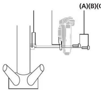
Installation on rear suspension types
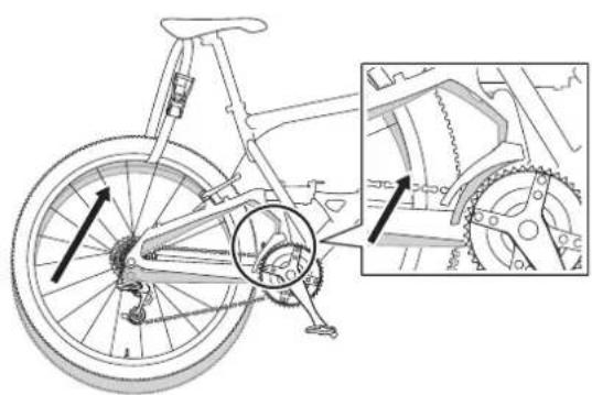
natural_image
Technical line drawing of a bicycle wheel assembly with gear mechanism and mechanical components (no text or symbols)
TECH TIPS
Bicycles with rear suspensions may be positioned differently when a rider is off the bicycle and on the bicycle. By referring to the illustration, perform installation and SIS adjustment while seated on the bicycle.
■ Installation of the front derailleur (Front triple)
Band type (FD-M9000/M8000/M672/M612)
Side swing
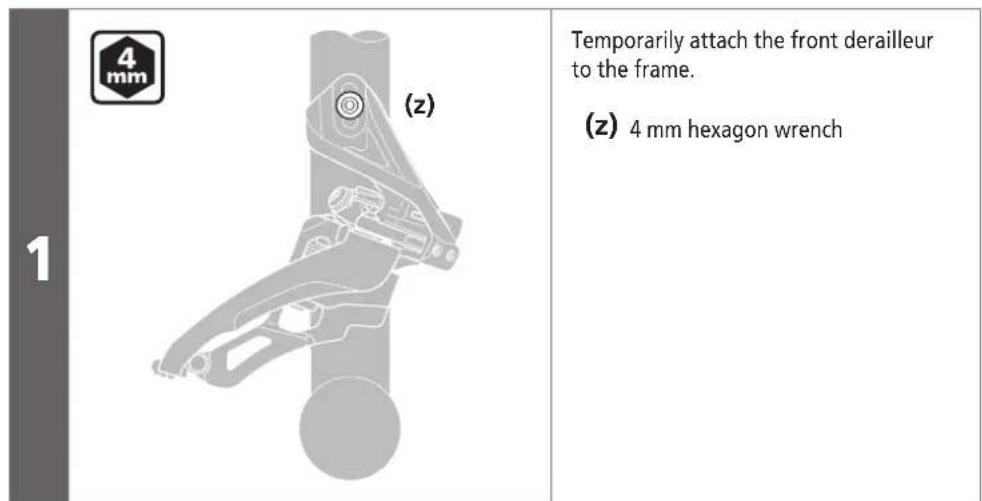
1
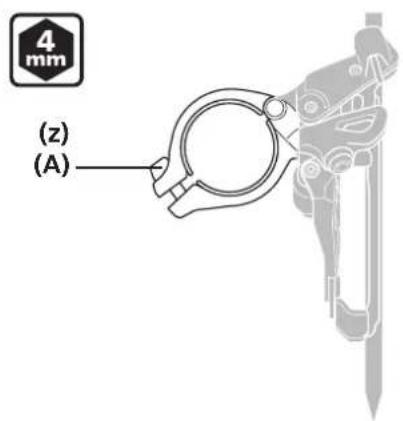
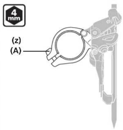
Temporarily attach the clamp bolt.
(z) 4 mm hexagon wrench
(A) Clamp bolt
![(A) [A-B] (B)](/content/2026/06/1194008/images/3e4051d4ab6d1b240688e668258f4c47a350f1adbb49eb367ad5365adb9ac426.jpg)
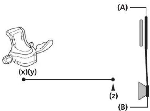
Align the flat portion of the chain guide outer plate in parallel with the flat surface of the largest chainring.
Make sure that distance [A-B] from the tip of the teeth of the largest chainring is 1 to 3 mm.
[A-B] 1 - 3 mm
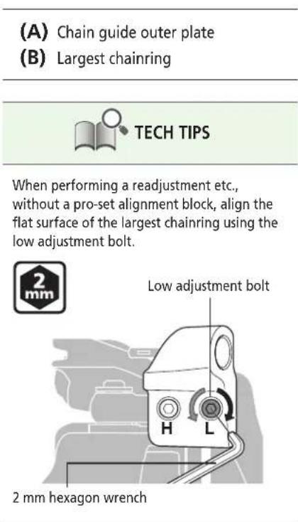
(A) Chain guide outer plate
(B) Largest chainring

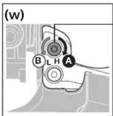
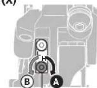
TECH TIPS
- Check by holding a hexagon wrench against the flat surface of the largest chainring as shown in the illustration.
natural_image
Mechanical assembly diagram showing a hand operating a gear with a clamping tool (no text or symbols)- When performing a readjustment etc., without a pro-set alignment block, align the flat surface of the largest chainring using the low adjustment bolt.
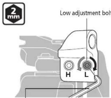
2 mm hexagon wrench
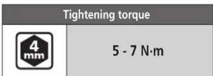
When adjustment is complete, tighten the clamp bolt.
Tightening torque

5 - 7 N·m
Direct mount type (FD-M9000/M8000/M672/M612)
Side swing
![2 (A) [A-B] (B) Align the flat portion of the chain guide outer plate in parallel with the flat surface of the largest chainring. Make sure that distance [A-B] from the tip of the teeth of the largest chainring is 1 to 3 mm. [A-B] 1 - 3 mm](/content/2026/06/1194008/images/02cbe701d302bb80669f891cc91910c7e98ff0786a7f1f2c584f432b576f9e7d.jpg)

Type E (FD-M9000/M8000/M672/M612)
Side swing
| 1 | 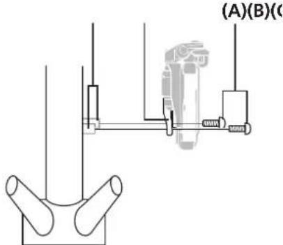 | Install the front derailleur with bottom bracket mount fixing bolts. |
Fixing position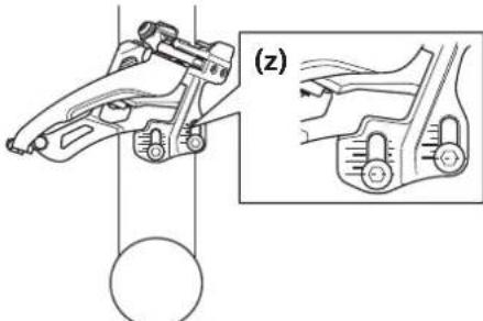 | Largest chainring(z) 40T |

| 2 | 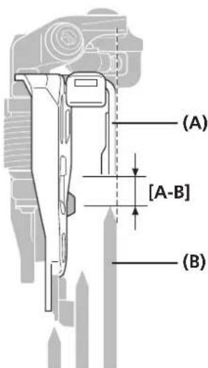 | Align the flat portion of the chain guide outer plate in parallel with the flat surface of the largest chainring.Make sure that distance [A-B] from the tip of the teeth of the largest chainring is 1 to 3 mm after installing the front chainwheel.If the clearance does not fall within the range, adjust the fixing position with the elongated hole and fix the fixing bolt again.[A-B] 1 - 3 mm |

When performing a readjustment etc., without a pro-set alignment block, align the flat surface of the largest chainring using the low adjustment bolt.
■ Installation of the front derailleur (Front double)
Band type (FD-M9020/M8020/M617/M677)
Side swing
1
Temporarily attach the clamp bolt.
(z) 4 mm hexagon wrench
(A) Clamp bolt
2
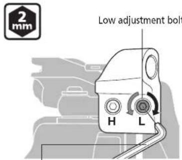
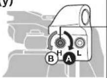
![2 mm (z) (A) H L (B) [B-C] (C)](/content/2026/06/1194008/images/a78e3c4ebe4ccad8ea495312054f41b952e0ec099d77b251c3b15fbd116b6168.jpg)
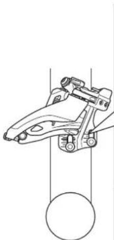
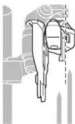
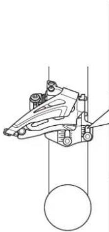
Adjust the low adjustment bolt and align the flat portion of the chain guide outer plate parallel to the flat surface of the largest chainring.
Make sure that distance [B-C] from the tip of the teeth of the largest chainring is 1 to 3 mm.
[B-C] 1 - 3 mm
(z) 2 mm hexagon wrench
(A) Low adjustment bolt
(B) Chain guide outer plate
(C) Largest chainring
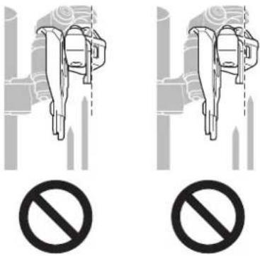
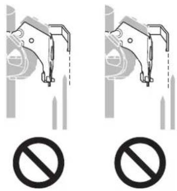
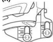
NOTE
Make sure not to position the chain guide as shown in the illustration.
3
When adjustment is complete, tighten the clamp bolt.
Tightening torque

5 - 7 N·m
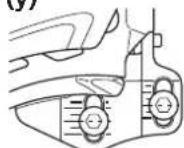
Band type (FD-M9025/M8025/M618)
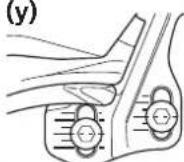
Top swing/Down swing
| 1 | 4 mm (z) (A) | Temporarily attach the clamp bolt. (z) 4 mm hexagon wrench |
(A) Clamp bolt
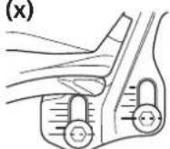
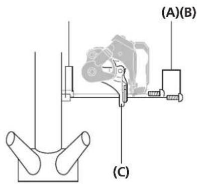
Adjust the low adjustment bolt and align the flat portion of the chain guide outer plate parallel to the flat surface of the largest chainring. Make sure that distance [B-C] from the tip of the teeth of the largest chainring is 1 to 3 mm.

![(y)(x) (z) (A) (z) (A) (B) [B-C] (C)](/content/2026/06/1194008/images/31aa0c61ea41552bdfda3cb1adeedcbf7251e6e213de8f1744f7ffdeb3fc9061.jpg)
[B-C] 1 - 3 mm
(x) Top swing
(y) Down swing
(z) 2 mm hexagon wrench
(A) Low adjustment bolt
(B) Chain guide outer plate
(C) Largest chainring
NOTE
Make sure not to position the chain guide as shown in the illustration.

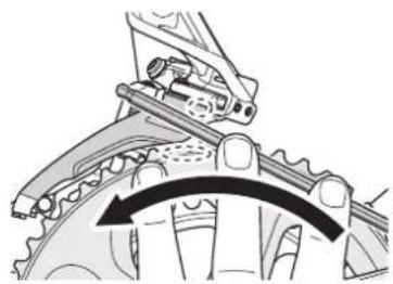
TECH TIPS
Check by holding a hexagon wrench against the flat surface of the largest chainring as shown in the illustration.
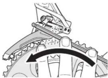
natural_image
Mechanical gear assembly diagram showing a chain with a rotating arrow indicating rotational motion (no text or symbols)When adjustment is complete, tighten the clamp bolt.
Tightening torque

5 - 7 N·m
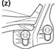
Direct mount type (FD-M9020/M8020/M617/M677)
Side swing
1
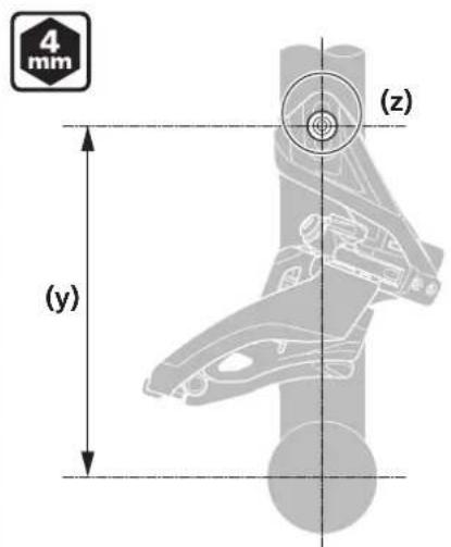
Temporarily attach the front derailleur to the frame.
(y) Installation height
(z) 4 mm hexagon wrench
NOTE
Compatible chainrings vary depending on the installation height. Be sure to check the dimensions of the frame.
| Installation height | Largest compatible chainring |
| 155.5 mm 34T - 36T | |
| 159.5 mm 36T - 38T |
2
![2 mm (z) H L (A) [A-B] (B)](/content/2026/06/1194008/images/b5a597bd09a5234b4666c1be1a80c9a60d33931208b77c4f4713b16ed092b2cb.jpg)
Adjust the low adjustment bolt and align the flat portion of the chain guide outer plate parallel to the flat surface of the largest chainring.
Make sure that distance [A-B] from the tip of the teeth of the largest chainring is 1 to 3 mm.
[A-B] 1 - 3 mm
(z) 2 mm hexagon wrench
(A) Chain guide outer plate
(B) Largest chainring
NOTE
Make sure not to position the chain guide as shown in the illustration.
3
When adjustment is complete, secure the front derailleur to the frame.
Tightening torque

5 - 7 N·m
Direct mount type (FD-M9025/M8025/M618)
Down swing
1
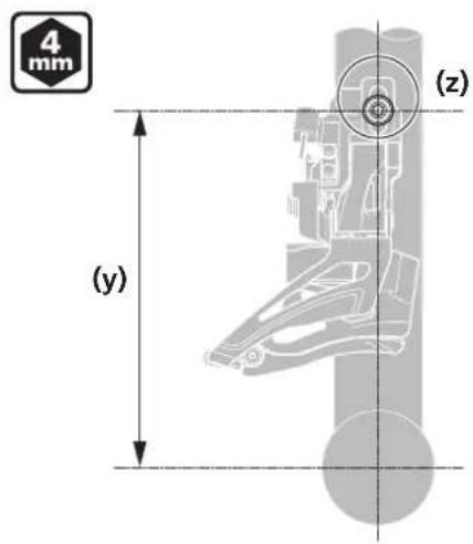
Temporarily attach the front derailleur to the frame.
(y) Installation height
(z) 4 mm hexagon wrench
NOTE
Compatible chainrings vary depending on the installation height. Be sure to check the dimensions of the frame.
| Installation height | Largest compatible chainring |
| 155.5 mm 34T - 36T | |
| 159.5 mm 36T - 38T |
2

![(z) (A) [A-B] (B)](/content/2026/06/1194008/images/eb8d88bd514c6b7deebc3b4015f7a23c892146ef0cfa71ec4a1090f4951ed725.jpg)
Adjust the low adjustment bolt and align the flat portion of the chain guide outer plate parallel to the flat surface of the largest chainring.
Make sure that distance [A-B] from the tip of the teeth of the largest chainring is 1 to 3 mm.
[A-B] 1 - 3 mm
(z) 2 mm hexagon wrench
(A) Chain guide outer plate
(B) Largest chainring
NOTE
Make sure not to position the chain guide as shown in the illustration.
3
When adjustment is complete, secure the front derailleur to the frame.
Tightening torque

5 - 7 N·m
Type E (FD-M9020/M8020/M617/M677)
Side swing
1
Fixing position
natural_image
Technical line drawing of a mechanical clamp or bracket assembly (no text or symbols)(x)
(y)
(z)
Secure with bottom bracket mount fixing bolts.
Fixing position varies depending on the number of gear teeth used.
Refer to the illustration for fixing position.
Largest chainring
(x) 38T
(y) 36T
(z) 34T
(A) Bottom bracket mount fixing bolt
(B) Bottom bracket mount
(C) Bracket
NOTE
Shimano does not provide the bottom bracket mount fixing bolts.
2

![(A) [A-B] (B)](/content/2026/06/1194008/images/63af2f730ec7d014f4ff225b13aec09ddd9130349b80396d966a57a34fdc030b.jpg)
Adjust the low adjustment bolt and align the flat portion of the chain guide outer plate parallel to the flat surface of the largest chainring.
Make sure that distance [A-B] from the tip of the teeth of the largest chainring is 1 to 3 mm after installing the front chainwheel.
If the clearance does not fall within the range, adjust the fixing position with the elongated hole and fix the fixing bolt again.
[A-B] 1 - 3 mm
(z) 2 mm hexagon wrench
(A) Chain guide outer plate
(B) Largest chainring
NOTE
Make sure not to position the chain guide as shown in the illustration.


Type E (FD-M9025/M8025/M618)
Top swing
1
Fixing position
natural_image
Technical line drawing of a mechanical clamp or bracket assembly (no text or symbols)(x)
(y)
(z)
Secure with bottom bracket mount fixing bolts.
Fixing position varies depending on the number of gear teeth used.
Refer to the illustration for fixing position.
Double: Largest chainring
(x) 38T
(y) 36T
(z) 34T
(A) Bottom bracket mount fixing bolt
(B) Bottom bracket mount
(C) Bracket
NOTE
Shimano does not provide the bottom bracket mount fixing bolts.
2
Adjust the low adjustment bolt and align the flat portion of the chain guide outer plate parallel to the flat surface of the largest chainring.
Make sure that distance [A-B] from the tip of the teeth of the largest chainring is 1 to 3 mm after installing the front chainwheel.
If the clearance does not fall within the range, adjust the fixing position with the elongated hole and fix the fixing bolt again.
![2 mm (z) (A) [A-B] (B)](/content/2026/06/1194008/images/5c5789bc1ce834f473f0f94f872e2253b02aa1ed7523bdbfae3f052610c1570d.jpg)
[A-B] 1 - 3 mm
(z) 2 mm hexagon wrench
(A) Chain guide outer plate
(B) Largest chainring
NOTE
Make sure not to position the chain guide as shown in the illustration.
ADJUSTMENT
ADJUSTMENT
Adjustment procedures differ depending on whether the bicycle features front triples or front doubles. Before making adjustments, check the specifications of the bicycle.
☐ Installing the cable and adjusting shifting operation (Front triple)
Position adjustment of the low side
1
natural_image
Mechanical linkage component diagram showing a bracket and pin assembly (no text or symbols)Remove the Pro-Set alignment block.
(A) Pro-Set alignment block
2
Adjust the chain position to the smallest chainring and the largest sprocket as shown in the illustration.
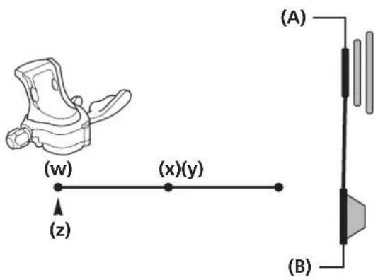
(w) Low
(x) Middle
(y) Top
(z) Cable index point
(A) Smallest chainring
(B) Largest sprocket
![2 mm 3 (w) L H B A (z) (A) (x) (b) L H A (b) L H A (y) H B A (b) L H A (b) L H A [B-C] [A]](/content/2026/06/1194008/images/2adb1f43d49bbeba5a80224d4882bab0964cbef69cbe0a65b61d5525196151d2.jpg)
Adjust the position of the chain guide with the low adjustment bolt. Adjust the clearance [B-C] between the chain guide inner plate and the chain to be 0 to 0.5 mm.
[B-C] 0 - 0.5 mm
(w) Top swing
(x) Down swing
(y) Side swing
(z) 2 mm hexagon wrench
(A) Low adjustment bolt
(B) Chain guide inner plate
(C) Chain
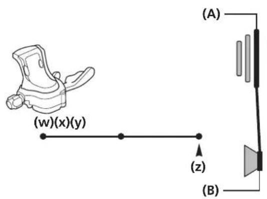
Securing the cable
Side swing (FD-M9000/M8000/M672/M612)
1
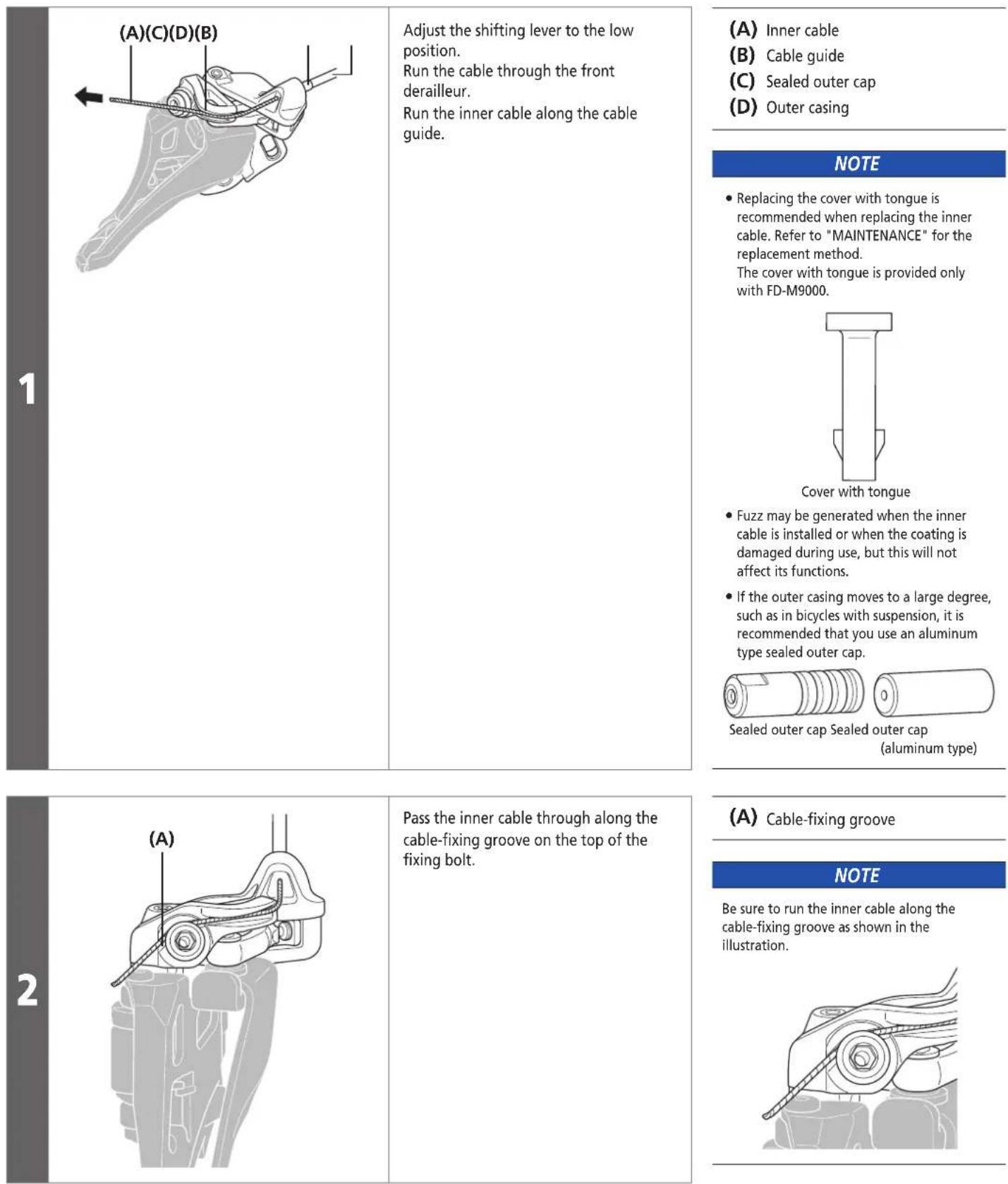
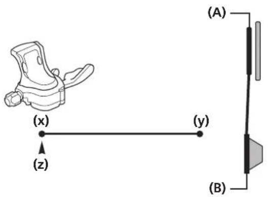
Adjust the shifting lever to the low position.
Run the cable through the front derailleur.
Run the inner cable along the cable guide.
(A) Inner cable
(B) Cable guide
(C) Sealed outer cap
(D) Outer casing
NOTE
- Replacing the cover with tongue is recommended when replacing the inner cable. Refer to "MAINTENANCE" for the replacement method.
The cover with tongue is provided only with FD-M9000.
- Fuzz may be generated when the inner cable is installed or when the coating is damaged during use, but this will not affect its functions.
- If the outer casing moves to a large degree, such as in bicycles with suspension, it is recommended that you use an aluminum type sealed outer cap.
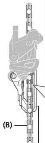
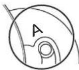
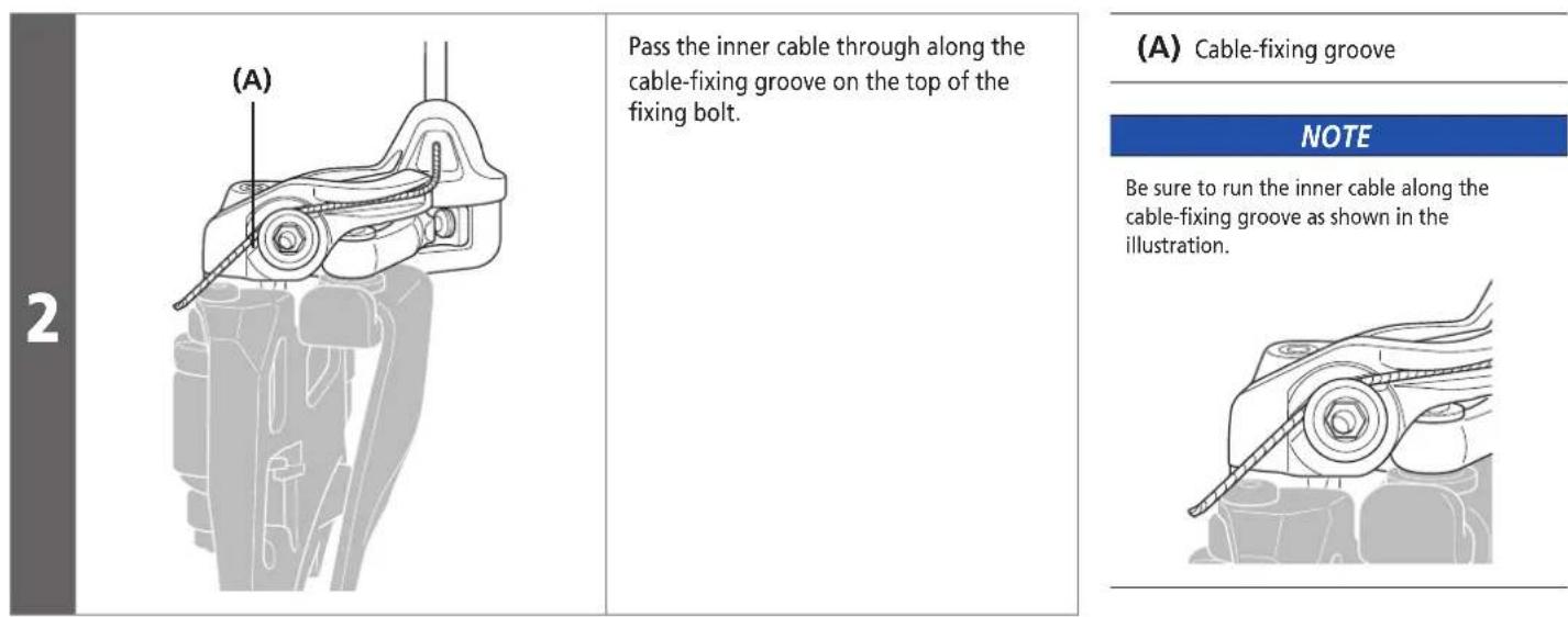
(A) Cable-fixing groove
NOTE
Be sure to run the inner cable along the cable-fixing groove as shown in the illustration.
2
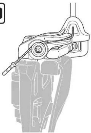
Pass the inner cable through along the cable-fixing groove on the top of the fixing bolt.
Installing the cable and adjusting shifting operation (Front triple)
3

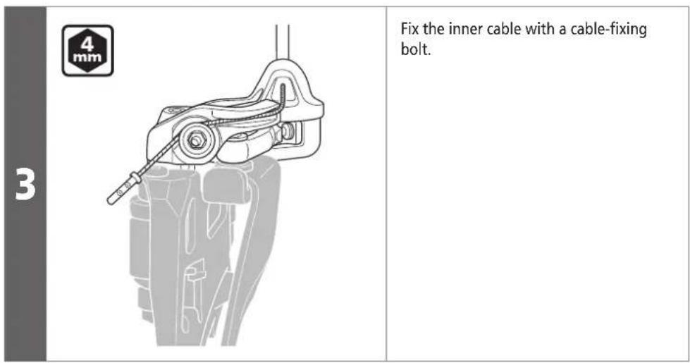
natural_image
Mechanical assembly diagram showing a clamp or bracket with a tool inserted (no text or symbols visible)Fix the inner cable with a cable-fixing bolt.
Tightening torque

6 - 7 N·m
Adjustment of the cable tension
1
Adjust the chain position to the middle chainring and the largest sprocket as shown in the illustration.
(w) Low
(x) Middle
(y) Top
(z) Cable index point
(A) Middle chainring
(B) Largest sprocket
NOTE
Adjust the lever after operating it from top to middle, not low to middle.
2
![(A) (B) A [B-C] (B) (C)](/content/2026/06/1194008/images/4d97c7ad8acc2a72dd821b4a773686f4694f86cd8d84ed4c8b5dd6656ed6e29d.jpg)
Adjust the position with the cable adjuster. Adjust the clearance [B-C] between the chain guide inner plate and the chain to be 0 to 0.5 mm.
[B-C] 0 - 0.5 mm
(A) Cable adjuster
(B) Chain guide inner plate
(C) Chain

TECH TIPS
After adjusting the position with the cable adjuster, operate the lever once and check the clearance again.
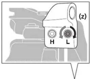
Top adjustment
1
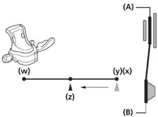
Adjust the chain position to the largest chainring and the smallest sprocket as shown in the illustration.
(w) Low
(x) Middle
(y) Top
(z) Cable index point
(A) Largest chainring
(B) Smallest sprocket

natural_image
Mechanical assembly diagram showing a vertical rod with internal components and a labeled section (B), no readable text or symbols present.(C)
(z)
(A)
(x)
(z)
(A)
(y)
(z)
(A)
![[B-C] A B](/content/2026/06/1194008/images/ebe6046a207533580f1199a9fea1a28b98f285f676875d17c7cd47f868f1420d.jpg)
Adjust the position of the chain guide with the top adjustment bolt. Adjust the clearance [B-C] between the chain guide outer plate and the chain to be 0 to 0.5 mm.
[B-C] 0 - 0.5 mm
(w) Top swing
(x) Down swing
(y) Side swing
(z) 2 mm hexagon wrench
(A) Top adjustment bolt
(B) Chain
(C) Chain guide outer plate
Checking gear shifting and minor adjustments
After the cable is installed and adjusted, check the gear-shift by operating the shifting lever.
(This also applies if shifting becomes difficult during use.)
Use the table as a reference when adjusting the bolts. Turn the bolt by 1/8th turn for each adjustment.
| If the chain falls to the crank side. Turn the top adjustment bolt clockwise. | |
| If shifting is difficult from the middle chainring to the largest chainring. | Tighten the cable. If this does not improve the situation, turn the top adjustment bolt counterclockwise. |
| If shifting is difficult from the largest chainring to the middle chainring. | Loosen the cable. |
| If the chain falls to the bottom bracket side. Turn the low adjustment bolt clockwise. | |
| If the middle chainring is skipped when shifting from the largest chainring. | Tighten the cable. |
| If shifting is difficult from the middle chainring to the smallest chainring. | Turn the low adjustment bolt counterclockwise. |
■ Installing the cable and adjusting shifting operation (Front double)
Note: Number of front chainring positions and lever position
The procedure for operating the shifting lever is as follows.
For double front chainrings
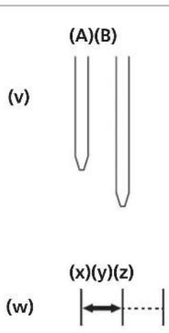
Use the low and middle positions of the shifter. The top position is not used.
(v) Front chainring position
(w) Shifting lever position
(x) Low
(y) Middle
(z) Top
(A) Smallest chainring
(B) Largest chainring
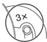
Note: Using the mode converter
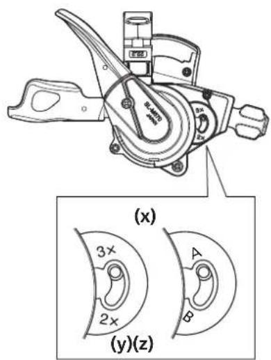
(x) Converter in detail
(y) Old
(z) New

TECH TIPS
Mode converter positions on the shifting lever
Position adjustment of the low side
1
Adjust the chain position to the smallest chainring and the largest sprocket as shown in the illustration.
(x) Low
(y) Top
(z) Cable index point
(A) Smallest chainring
(B) Largest sprocket
2
![(w) (b) H A (z) (A) (x) (b) L H A (z) (A) (y) (b) H B A (a) (b) A [B-C]](/content/2026/06/1194008/images/43294d9ab741d32fb499b7d953ecf928721ab4763f877e9c7f17db65183b3b1e.jpg)
Adjust the position of the chain guide with the low adjustment bolt. Adjust the clearance [B-C] between the chain guide inner plate and the chain to be 0 to 0.5 mm.
[B-C] 0 - 0.5 mm
(w) Top swing
(x) Down swing
(y) Side swing
(z) 2 mm hexagon wrench
(A) Low adjustment bolt
(B) Chain guide inner plate
(C) Chain
Securing the cable
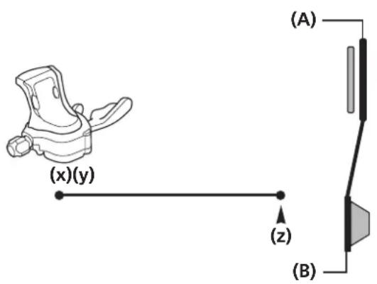
Side swing (FD-M9020/M8020/M617/M677)
| 1 | (A)(C)(D)(B) | Adjust the shifting lever to the low position. Run the cable through the front derailleur. Run the inner cable along the cable guide. | (A) Inner cable (B) Cable guide (C) Sealed outer cap (D) Outer casing |
| NOTE • Replacing the cover with tongue is recommended when replacing the inner cable. Refer to "MAINTENANCE" for the replacement method. The cover with tongue is provided only with FD-M9020. Cover with tongue • Fuzz may be generated when the inner cable is installed or when the coating is damaged during use, but this will not affect its functions. • If the outer casing moves to a large degree, such as in bicycles with suspension, it is recommended that you use an aluminum type sealed outer cap. Sealed outer cap Sealed outer cap (aluminum type) |
Top swing (FD-M9025/M8025/M618)
Common to E Type and band type
Down swing (FD-M9025/M8025/M618)
Band type
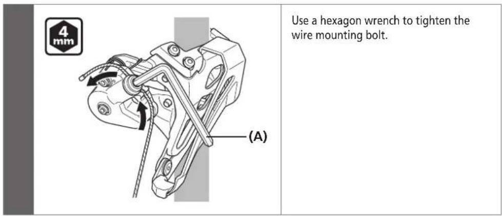
| 4 mm (y)(z) (A)(A) | For down-pull types: Pass the inner cable through the cable guide. For top-pull types: Pass the inner cable through the wire mounting bolt. A cable guide is not used. (y) Down pull (z) Top pull |
| Tightening torque | |
| 6 - 7 N·m | |
(A) 4 ~mm hexagon wrench
| Tightening torque | |
| 6 - 7 N·m | |
(A) 4 mm hexagon wrench
| Tightening torque | |
| 6 - 7 N·m | |
Direct mount type
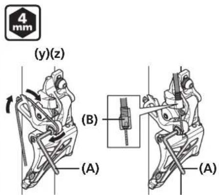
For down-pull types:
Pass the inner cable through the cable guide.
For top-pull types:
Install the sealed outer cap and pass the inner cable through the wire mounting bolt.
A cable guide is not used.
(y) Down pull
(z) Top pull
(A) 4 mm hexagon wrench
(B) Sealed outer cap
Tightening torque

6 - 7 N·m
NOTE
- Replacing the cover with tongue is recommended when replacing the inner cable. Refer to "MAINTENANCE" for the replacement method. The cover with tongue is provided only with FD-M9025.
Cover with tongue
- Fuzz may be generated when the inner cable is installed or when the coating is damaged during use, but this will not affect its functions. - If the outer casing moves to a large degree, such as in bicycles with suspension, it is recommended that you use an aluminum type sealed outer cap.
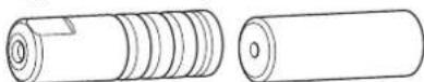
Sealed outer cap Sealed outer cap
(aluminum type)
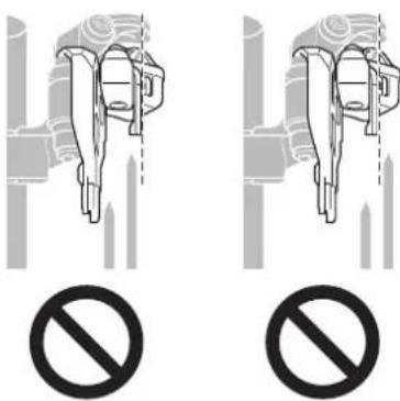
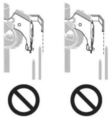
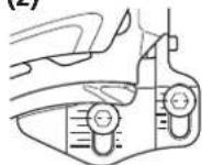
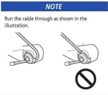
- Run the cable through as shown in the illustration.
natural_image
Two diagrams showing a rope being inserted into a cylindrical component, with a prohibition symbol below (no text or labels)Adjustment of the cable tension
1
Adjust the chain position to the largest chainring and the largest sprocket as shown in the illustration.
(x) Low
(y) Top
(z) Cable index point
(A) Largest chainring
(B) Largest sprocket
2
![[B-C] (B) (C) B A](/content/2026/06/1194008/images/301138bf4b6daa1cf5fcadf50c5b05f5655e78852d0e48aef572324b88237b74.jpg)
Adjust the position with the cable adjuster.
Adjust the clearance [B-C] between the chain guide inner plate and the chain to be 0 to 0.5 mm.
[B-C] 0 - 0.5 mm
(A) Cable adjuster
(B) Chain guide inner plate
(C) Chain

TECH TIPS
After adjusting the position with the cable adjuster, operate the lever once and check the clearance again.
Top adjustment
1
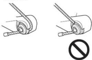
Adjust the chain position to the largest chainring and the smallest sprocket as shown in the illustration.
(x) Low
(y) Top
(z) Cable index point
(A) Largest chainring
(B) Smallest sprocket
(A) Top adjustment bolt
(B) Chain
(C) Chain guide outer plate
2
![(w) (z) (A) (x) (z) (A) (y) (z) (A) [B-C] [A] [B] (C)](/content/2026/06/1194008/images/4286be5abb315be2c12fcc74fc40576d32533e5dbe3750e9afbf294aabe46c23.jpg)
Adjust the position of the chain guide with the top adjustment bolt. Adjust the clearance [B-C] between the chain guide outer plate and the chain to be 0 to 0.5 mm.
[B-C] 0 - 0.5 mm
(w) Top swing
(x) Down swing
(y) Side swing
(z) 2 mm hexagon wrench
Checking gear shifting and minor adjustments
After the cable is installed and adjusted, check the gear-shift by operating the shifting lever.
(This also applies if shifting becomes difficult during use.)
Use the table as a reference when adjusting the bolts. Turn the bolt by 1/8th turn for each adjustment.
| If the chain falls to the crank side. Turn the top adjustment bolt clockwise. | |
| If shifting is difficult from the smallest chainring to the largest chainring. | Tighten the cable. If this does not improve the situation, turn the top adjustment bolt counterclockwise. |
| If shifting is difficult from the largest chainring to the smallest chainring. | Loosen the cable. |
| If the chain falls to the bottom bracket side. | Tighten the cable. If this does not improve the situation, turn the low adjustment bolt clockwise. |
MAINTENANCE
MAINTENANCE
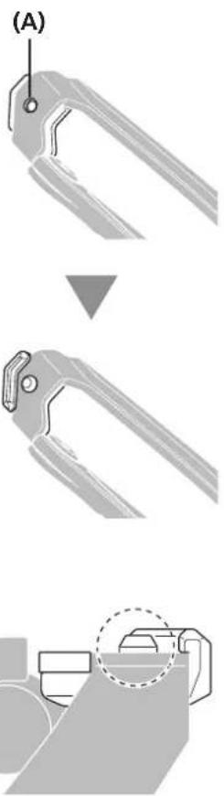
■ Replacing the chain catcher
Depending on the specifications, there are also models without a chain catcher.
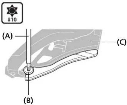
Removal
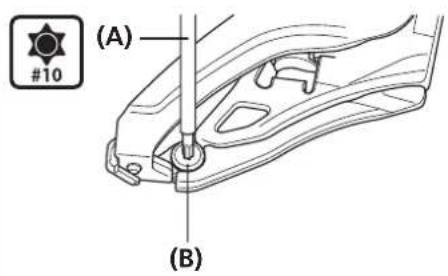
Remove the fixing bolt.
(A) Hexalobular[#10]
(B) Fixing bolt
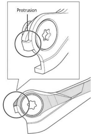
Installation
1
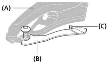
Temporarily attach the chain catcher to the chain guide.
(A) Chain guide
(B) Chain catcher
(C) Arm of the chain catcher
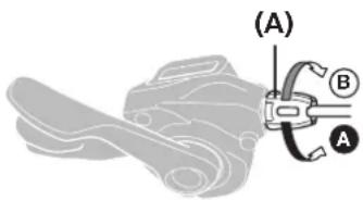
2
natural_image
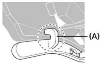
Diagram of a mechanical component with a highlighted section (A), no visible text or symbolsSecurely attach the arm of the chain catcher as shown in the illustration.
(A) Arm of the chain catcher
NOTE
- The shape of the chain catcher may differ depending on the model. Be sure to use a compatible chain catcher.
- In the case of a chain catcher such as shown in the illustration, take notice of the protrusion positions while carrying out replacement.
3
Fix the chain catcher to the chain guide inner plate.
(A) Hexalobular[#10]
(B) Fixing bolt
(C) Chain guide inner plate
Tightening torque
| #10 |
1 - 2 N·m
■ Replacing rubber pad A
Depending on the specifications, there are also models without rubber pad A.
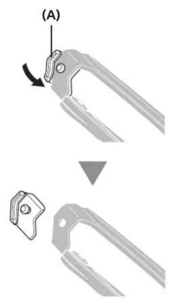
Removal
| 1 | 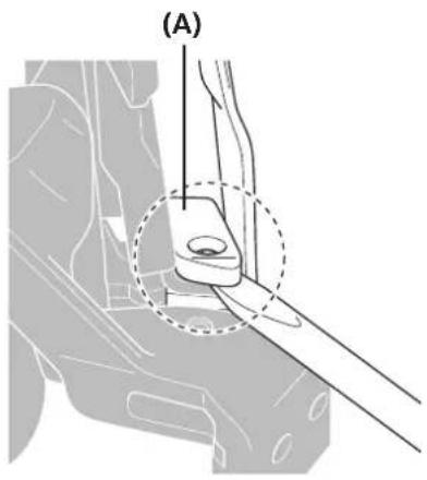 | Remove rubber pad A.Insert a small slotted screwdriver into the gap as shown in the illustration. | (A) Rubber pad A |
| 2 | 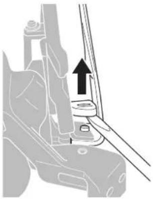 | Lift upward to remove it. | NOTEWhen removing rubber pad A, do not apply excessive force. It may cause damage to the chain guide or unexpected injuries.Do not reuse rubber pads that have been removed. The rubber pad may become loose easily due to deformation etc. |
NOTE
Installation
1
Install rubber pad A.
Fit the elongated hole to the arm of rubber pad A.
Push in the arm of rubber pad A all the way.
(A) Arm of rubber pad A
(B) Elongated hole
2
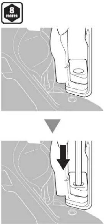
Align the protrusion of rubber pad A with the chain guide hole.
Lightly push in rubber pad A with an 8 mm hexagon wrench.
Firmly insert rubber pad A.
■ Replacing rubber pad B
Removal
Peel back rubber pad B from the reverse side of the chain guide and remove it.
(A) Rubber pad B
Installation
Align the rubber pad B mounting hole of the chain guide with the protrusion of rubber pad B. Push in the protrusion from the reverse side of rubber pad B. Make sure that the protrusion of rubber pad B is securely fitted on the chain guide.
(A) Rubber pad B mounting hole
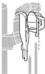
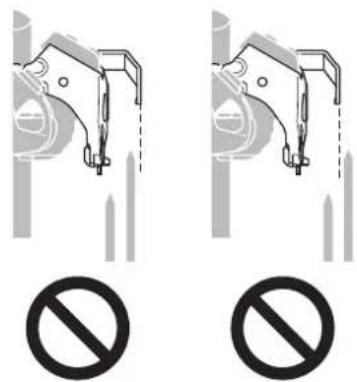
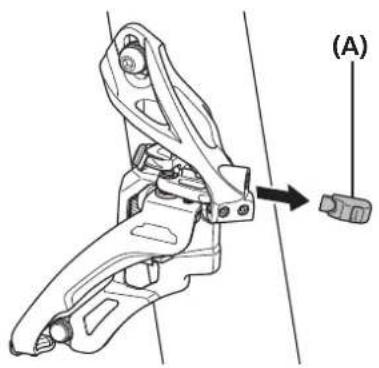
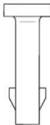
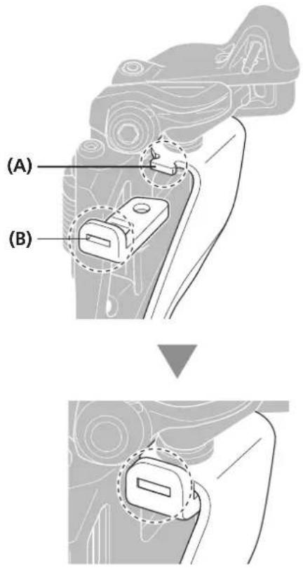
■ Replacing the cover with tongue
Removal
natural_image
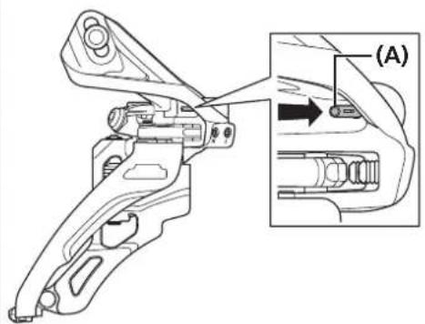
Technical line drawing of a mechanical tool or bracket assembly with an inset view showing a close-up of the component (no text or symbols present)Push the cover with tongue in the direction of the arrow, and then remove it from the bracket.
(A) Cover with tongue
Installation
Insert the new cover with tongue into the bracket, and then push it in until the burred section springs out.
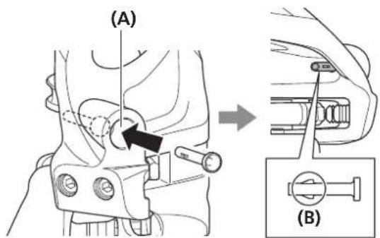
(A) Bracket
(B) Burred section
SHIMANO
SHIMANO AMERICAN CORPORATION
One Holland, Irvine, California 92618, U.S.A. Phone: +1-949-951-5003
SHIMANO EUROPE B.V.
High Tech Campus 92, 5656 AG Eindhoven, The Netherlands Phone: +31-402-612222
SHIMANO INC.
3-77 Oimatsu-cho, Sakai-ku, Sakai-shi, Osaka 590-8577, Japan
Please note: specifications are subject to change for improvement without notice. (English)
© Jun. 2017 by Shimano Inc. ITP