AR7261 - SSD APC - Free user manual and instructions
Find the device manual for free AR7261 APC in PDF.

User questions about AR7261 APC
0 question about this device. Answer the ones you know or ask your own.
Ask a new question about this device
Download the instructions for your SSD in PDF format for free! Find your manual AR7261 - APC and take your electronic device back in hand. On this page are published all the documents necessary for the use of your device. AR7261 by APC.
USER MANUAL AR7261 APC
Installation and Customization
NetShelter SX 12U, 18U, and 24U Cabinets
AR3003/AR3003SP, AR3103/AR3103SP, AR3006/AR3006SP, AR3106/AR3106SP, AR3104/AR3104SP1
990-3206C-001
Release date: 5/2019
natural_image
Line drawing of a rectangular cabinet with doors and wheels (no text or symbols)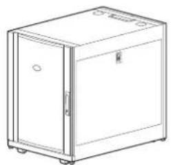
natural_image
Line drawing of a simple rectangular cabinet or enclosure with doors and wheels (no text or symbols)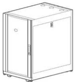
natural_image
Line drawing of a simple refrigerator with doors and wheels (no text or symbols)Legal Information
The Schneider Electric brand and any trademarks of Schneider Electric SE and its subsidiaries referred to in this guide are the property of Schneider Electric SE or its subsidiaries. All other brands may be trademarks of their respective owners.
This guide and its content are protected under applicable copyright laws and furnished for informational use only. No part of this guide may be reproduced or transmitted in any form or by any means (electronic, mechanical, photocopying, recording, or otherwise), for any purpose, without the prior written permission of Schneider Electric.
Schneider Electric does not grant any right or license for commercial use of the guide or its content, except for a non-exclusive and personal license to consult it on an "as is" basis. Schneider Electric products and equipment should be installed, operated, serviced, and maintained only by qualified personnel.
As standards, specifications, and designs change from time to time, information contained in this guide may be subject to change without notice.
To the extent permitted by applicable law, no responsibility or liability is assumed by Schneider Electric and its subsidiaries for any errors or omissions in the informational content of this material or consequences arising out of or resulting from the use of the information contained herein.
Table of Contents
Introduction....5
Important Safety Instructions — SAVE THESE
INSTRUCTIONS....6
Safety During Installation 7
Labels 7
Unpack the Cabinet....8
Disclaimer....8
Inspection 8
Please Recycle 8
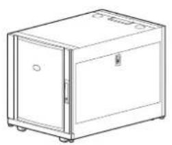
Component Identification....9
Cabinet....9
Hardware Bag 10
Cabinet Installation 11
Move the Cabinet 11
Level the Cabinet....12
Join the Cabinets....13
Secure the Cabinet ....14
Ground the Cabinet 15
Side Panels, Roof, and Doors....16
Side Panels....16
Roof 16
Doors 17
Remove the Doors ....17
Install the Doors....17
Reverse the Front Door 18
Equipment Installation....21
Vertical Mounting Flanges 21
Position the Vertical Mounting Flanges ....21
Adjust the Vertical Mounting Flanges....22
Install Equipment....23
Install a Cage Nut ....24
Remove a Cage Nut....24
Cable Management 25
Accessory Channel 25
Rear-door Cable-containment Bracket 25
Specifications 26
Five-year Factory Warranty....27
Terms of Warranty 27
Non-transferable Warranty 27
Exclusions 27
Warranty Claims 28
Introduction
The APC by Schneider Electric NetShelterX 600-mm (23.6-in) wide, 12-U, 18-U, and 24-U cabinets are high-quality cabinets for storage of industry-standard (EIA-310), 19-in rack-mount hardware, which includes servers and voice, data, networking, internetworking, and power protection equipment.
This manual covers the following NetShelter SX cabinets:
| Model Cabinet | mounting height | Cabinet depth | Cabinet mounting width | External cabinet width |
| AR3003/AR3003SP | 12 U | 900 mm(35.43 in) | 482 mm(18.98 in) | 600 mm(23.62 in) |
| AR3103/AR3103SP | 12 U | 1070 mm(42.13 in) | ||
| AR3006/AR3006SP | 18 U | 900 mm(35.43 in) | ||
| AR3106/AR3106SP | 18 U | 1070 mm(42.13 in) | ||
| AR3104/AR3104SP1 | 24 U | 1070 mm(42.13 in) |
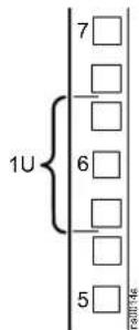
1U= 44.45 mm (1.75 in)
Important Safety Instructions — SAVE THESE INSTRUCTIONS
Read these instructions carefully and look at the equipment to become familiar with it before trying to install, operate, service or maintain it. The following safety messages may appear throughout this manual or on the equipment to warn of potential hazards or to call attention to information that clarifies or simplifies a procedure.

The addition of this symbol to a “Danger” or “Warning” safety message indicates that an electrical hazard exists which will result in personal injury if the instructions are not followed.

This is the safety alert symbol. It is used to alert you to potential personal injury hazards. Obey all safety messages with this symbol to avoid possible injury or death.
⚠️ DANGER
DANGER indicates a hazardous situation which, if not avoided, will result in death or serious injury.
Failure to follow these instructions will result in death or serious injury.
▲WARNING
WARNING indicates a hazardous situation which, if not avoided, could result in death or serious injury.
Failure to follow these instructions can result in death, serious injury, or equipment damage.
▲CAUTION
CAUTION indicates a hazardous situation which, if not avoided, could result in minor or moderate injury.
Failure to follow these instructions can result in injury or equipment damage.
NOTICE
NOTICE is used to address practices not related to physical injury. The safety alert symbol shall not be used with this type of safety message.
Failure to follow these instructions can result in equipment damage.
Please Note
Electrical equipment should only be installed, operated, serviced, and maintained by qualified personnel. No responsibility is assumed by APC by Schneider Electric for any consequences arising out of the use of this material.
A qualified person is one who has skills and knowledge related to the construction, installation, and operation of electrical equipment and has received safety training to recognize and avoid the hazards involved.
Safety During Installation
▲WARNING
TIP HAZARD
- The cabinet can be tipped. Use extreme caution when unpacking or moving.
- Use at least two people to unpack and move the cabinet.
- Before moving the cabinet on its casters, load 158 kg (350 lb) of equipment into the bottom of the cabinet for extra stability.
- When moving the cabinet on its casters, make sure the leveling feet are up and push the cabinet from the front or rear.
Failure to follow these instructions can result in death, serious injury, or equipment damage.
▲WARNING
HEAVY EQUIPMENT
Use at least two people to unpack the cabinet.
Failure to follow these instructions can result in death, serious injury, or equipment damage.
Labels
Look for additional safety information affixed to the cabinet. See Move the Cabinet, page 11 for more information.
Unpack the Cabinet
Disclaimer
APC by Schneider Electric is not responsible for damage sustained during reshipment of this product.
Inspection
Inspect the packaging and contents for shipping damage. Make sure that all parts are accounted for. Report any damage immediately to the shipping agent. Report missing contents, damage, or other problems immediately to APC by Schneider Electric or your reseller.
Please Recycle

The shipping materials are recyclable. Save them for later use, or dispose of them appropriately.
Component Identification
Cabinet

① Cabinet frame
8 Hardware bag
② Removable side panels with locks Bolt-dow ^9 bracket
③ Removable rear split door
10 Removable and reversible front door
4 Cable containment bracket (AR3104/AR3104SP1 only)
⑪ Key for doors and side panels
5 Adjustable vertical 0 U accessory channel
12 Nameplate (if equipped)
6 Adjustable leveling feet Vertical mounting
Enges
⑦ Casters Removable roof
14
Hardware Bag

Plastic cup washers (60)

M6 x 16 PHillips slot screws (60)

M5 x 12 screws (4)

Cage nuts (60)

7-mm (0.28 in) hole plugs (4)
Tools (provided)
TORX® T30/#2 Phillips tool (1)
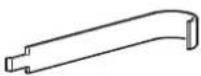
Cage nut tool (1)
Cabinet Installation
Move the Cabinet

1
2

3
natural_image
Technical line drawing of a crane lifting a box, no text or symbols present▲WARNING
TIP HAZARD
- The cabinet can be tipped. Use extreme caution when unpacking or moving.
- Use at least two people to unpack and move the cabinet.
- Before moving the cabinet on its casters, load 158 kg (350 lb) of equipment into the bottom of the cabinet for extra stability.
- When moving the cabinet on its casters, make sure the leveling feet are up and push the cabinet from the front or rear.
Failure to follow these instructions can result in death, serious injury, or equipment damage.
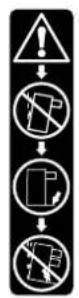
Labels. The following labels can be found on the cabinet, and serve to communicate the following information:
Label ① Generic Tip Hazard
Label ②: Extend Slide-Mounted Hardware One Piece at a Time. Do not extend loaded top-mounted sliding hardware unless the cabinet is secured to the floor.
Casters. The cabinets can be loaded and moved on their casters as follows:
| Cabinet Height | 12 U 18 U | 24 U | |
| Maximum Load | 272 kg (600 lb) | 408 kg (900 lb) | 1 021 kg (2,250 lb) |
With the leveling feet lowered, the static cabinets can be loaded as follows:
| Cabinet Height | 12 U 18 U | 24 U | |
| Maximum Load | 272 kg (600 lb) | 408 kg (900 lb) | 1 361 kg (3,000 lb) |
NOTE: Some labels on cabinets indicate caster related information. See label ③ to the left.
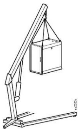
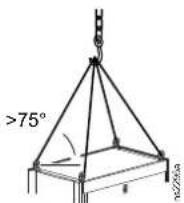
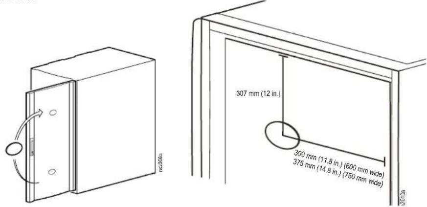
Eye bolts. The cabinet can be lifted by removing the hole plugs and attaching eye bolts (not included), to the top of the cabinet frame. Use rated M10 eye bolts. The maximum weight of installed equipment is as follows:
| Cabinet Height | 12 U 18 U | 24 U | |
| Maximum Load | 272 kg (600 lb) | 408 kg (900 lb) | 567 kg (1,250 lb) |
NOTE: Each eye bolt can lift 142 kg (312 lb) of loaded equipment in the cabinet. All four eye bolts can lift 567 kg (1250 lb) of loaded equipment.
NOTE: Each individual frame lift point is capable of lifting 255 kg (562 lb).
NOTE: If using supplemental lifting hardware, ensure the cord length allows for a minimum of a 75^ angle, as shown to the right.
Level the Cabinet
NOTE: The leveling feet at the corners of the equipment provide a stable base if the floor is uneven, but they cannot compensate for a badly sloped surface.
- Ensure the cabinet is in its intended location. Remove the front and rear doors. See Remove the Doors, page 17 for instructions.
NOTE: Before removing the front doors, unplug the ground wires and any other wire connections that may interfere with the removal of the doors.
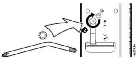
- Insert a Phillips head screwdriver into the screw above the leveling foot. Turn the screw clockwise to extend the leveling foot until it makes firm contact with the floor.
NOTE:
- This method works best with an empty, or near empty cabinet.
- If loaded with equipment, a 13-mm, open-ended wrench can also be used to lower the leveling feet.
- Door removal is not required if using the 13-mm, open-ended wrench.
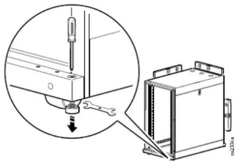
- Using a level, adjust each foot until the cabinet is level and plumb.
- Install the front and rear doors.
⚠️ DANGER
HAZARD OF ELECTRIC SHOCK
When installing the doors, reconnect all ground and other connection wires.
Failure to follow these instructions will result in death or serious injury.
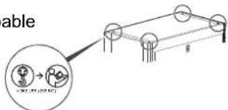
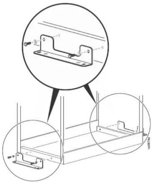
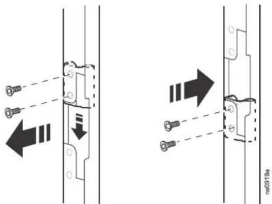
Join the Cabinets
Join cabinets with the provided brackets to provide alignment and added stability. Cabinets may be joined with or without the side panels installed.
- If installed, remove the front and rear doors. See Remove the Doors, page 17 for instructions.
- Choose between 24-in centers or 600-mm centers (see the illustration below). Align the cabinets and locate the joining brackets. There are two brackets on the front and two brackets on the back of each cabinet.
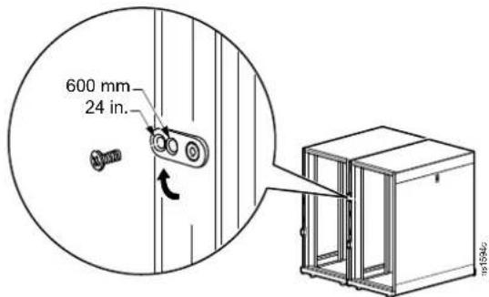
- Join the cabinets with an M5 x 12 countersunk screw (provided in the hardware bag). Using the Phillips head end of the provided tool or a similar tool, insert the screw into the designated hole and tighten.
- Install the doors. See Install the Doors, page 17 for instructions.
⚠️ DANGER
HAZARD OF ELECTRIC SHOCK
When installing the doors, reconnect all ground and other connection wires.
Failure to follow these instructions will result in death or serious injury.
Secure the Cabinet
Brackets can be used to bolt the cabinet to the floor internally or externally for additional stabilization. See www.apc.com for bracket installation and further related information.
NOTE: Only use the bolt-down bracket or stabilization plate with the casters or leveling feet installed.
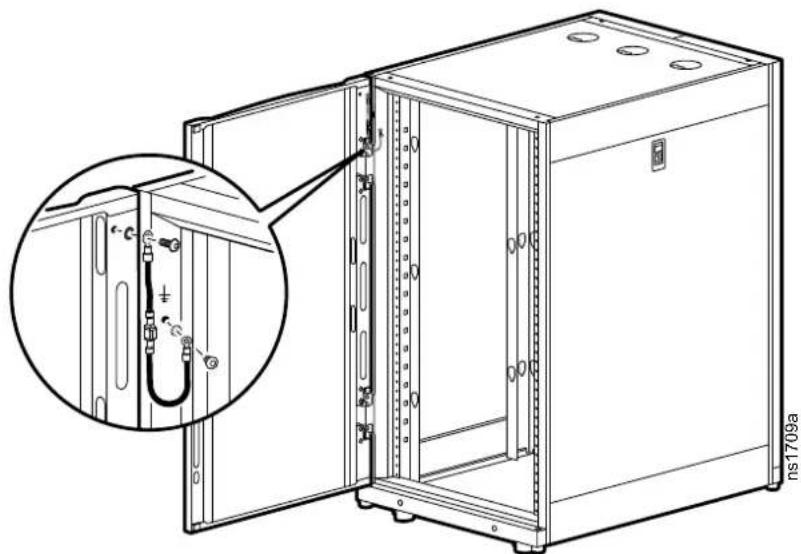
Ground the Cabinet
The doors, side panels, and roof of the cabinet are grounded to the cabinet frame. The doors are grounded with quick-disconnect cables. The roof and side panels are inherently grounded through spring fingers.
Each cabinet should be bonded directly to a common ground using one of the designated grounding locations (two M6 threaded inserts) at the bottom of the cabinet.
- Use a Common Bonding Network Jumper kit (for example, Listed [KDER] Panduit® RGCBNJ660PY or equivalent).
- Use paint-piercing washers between the ground terminal and the cabinet frame, or remove the paint on the frame under the ground terminals, per NEC NFPA 70 Article 250.12.
- Torque the screws to 6.9 N·m (60 lb-in).
- Do not ground one cabinet to another cabinet in a cascading style. Ground each cabinet directly to the building ground.
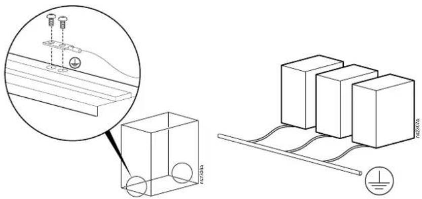
⚠️ DANGER
HAZARD OF ELECTRIC SHOCK
The cabinet must be connected to the building Common Bonding Network (CBN).
Failure to follow these instructions will result in death or serious injury.
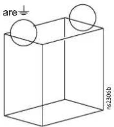
NOTE: If needed, additional functional grounding points available at the top of the cabinet. Do not connect the building CBN to the these functional grounding points.
Side Panels, Roof, and Doors
Side Panels
Roof
Doors
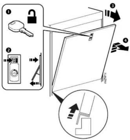
Remove the Doors
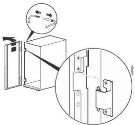
- Unlock the cabinet front door handle and open the door.
- Disconnect the ground wire and any other wire connections that may interfere with the removal of the doors.
- The hinges come apart by lifting upward and outward. Slowly lift and pull the door from the cabinet until the hinge pins on the door are free of the hinges of the cabinet frame.
Install the Doors
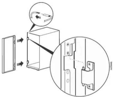
- The doors self-align on hinge pins when properly installed. With the door at a 90 degree angle to the front of the cabinet, position the door over the hinge pins.
- Slowly lower the door into the cabinet frame ensuring that the door hinges correctly align to the cabinet frame hinges.
- Connect the ground wire and any other wire connections. Make sure the door opens and closes properly.
⚠️ DANGER
HAZARD OF ELECTRIC SHOCK
When installing the doors, reconnect all ground and other connection wires.
Failure to follow these instructions will result in death or serious injury.
Reverse the Front Door
The front door can be reversed so that the door opens in the other direction. This procedure assumes that initially, when facing the cabinet, the hinges are on the left and the door is opening from right.
- Remove the handle by removing the screw-plate. Pull the handle from the door.
- Disconnect the ground wire, and any other wire connections. Remove the door from the frame. See Remove the Doors, page 17 for more information.
natural_image
Technical line drawing of an open server cabinet with internal wiring and mounting holes (no text or symbols)- Locate the upper hinge on the cabinet frame. Remove the two screws holding the hinge in place. Install the hinge onto the other side of the cabinet frame. Repeat this step for the lower hinge.
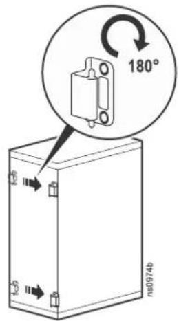
- Remove the hinges from the door and install them using the set of holes directly below where they were originally installed.
- Rotate the door 180 degrees. Install the door to the hinges now on the reverse side of the cabinet frame. See Install the Doors, page 17 for instructions. Connect the ground wire and any other wire connections previously disconnected.
⚠️ DANGER
HAZARD OF ELECTRIC SHOCK
When installing the doors, reconnect all ground and other connection wires.
Failure to follow these instructions will result in death or serious injury.
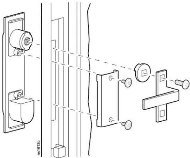
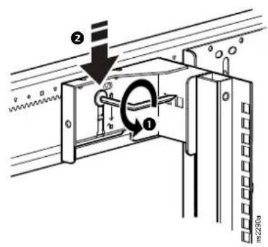
- Locate the lock handle. Remove the cam screw, cam washer, and cam. Rotate the cam washer 90 degrees, and the latch 180 degrees. Install the handle on the dock.
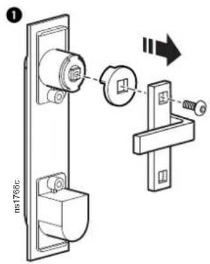
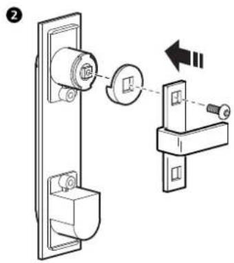
- Remove the nameplate (if equipped) from the door. Install the nameplate as shown.
Equipment Installation
NetShelter SX cabinets are intended for use with Listed equipment. If you install un-Listed equipment, you should evaluate the safety of your configuration.
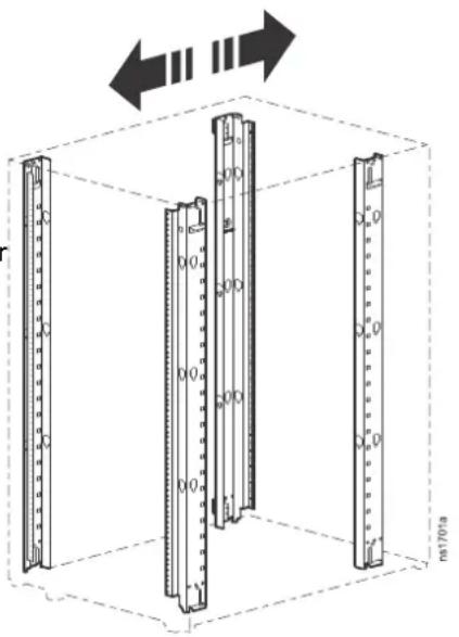
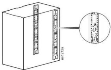
Vertical Mounting Flanges
Vertical mounting flanges come factory-installed at the proper location for use with rack-mountable equipment:
• 737 mm (29 in) for 1070-mm racks
• 641 mm (25 in) for 900-mm racks
The mounting flanges are adjustable towards the front or the rear of the cabinet to accommodate different rails or equipment with other depths.
natural_image
Diagram of three vertical cylindrical structures inside a cube, with arrows indicating direction (no text or symbols)Position the Vertical Mounting Flanges
Configuration ① The Accessory Channel is installed. The Vertical Mounting Flanges can be installed a minimum distance of (a) and can extend as far as (b).
Configuration ②: The Accessory Channel is removed. The Vertical Mounting Flanges can extend as far as (c).
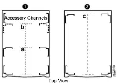
| Models | Cabinet Depth (D) | a b c | ||
| AR3003/AR3003SP | 900 mm(35.43 in) | 191 mm(7.5 in) | 654 mm(25.75 in) | 756 mm(29.75 in) |
| AR3103/AR3103SP | 1070 mm(42.13 in) | 781 mm(30.75 in) | 921 mm(36.25 in) | |
| AR3006/AR3006SP | 900 mm(35.43 in) | 654 mm(25.75 in) | 756 mm(29.75 in) | |
| AR3106/AR3106SP | 1070 mm(42.13 in) | 781 mm(30.75 in) | 921 mm(36.25 in) | |
| AR3104/AR3104SP1 | 1070 mm(42.13 in) | 781 mm(30.75 in) | 921 mm(36.25 in) |
Adjust the Vertical Mounting Flanges
▲WARNING
FALLING EQUIPMENT HAZARD
Remove all equipment installed on the vertical mounting flanges before performing any adjustments.
Failure to follow these instructions can result in death, serious injury, or equipment damage.
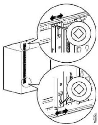
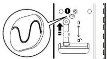
- Use the provided TORX T30 tool to loosen the top and bottom TORX screws ① holding the vertical mounting flange in place. The brackets held in place by the TORX screws will now be loose.
Move both brackets to the designated unlocked position.
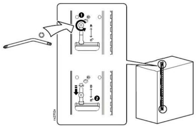
- Move the mounting flange to the desired location. Vertical mounting flanges adjust in 6 mm (1/4 in) increments.
To align the vertical mounting flange, note the symbol (for example, a diamond). Only one symbol will be visible. In the factory standard position, a circle symbol is visible. Make sure the same symbol is visible through the corresponding hole at both the top and the bottom of the flange.
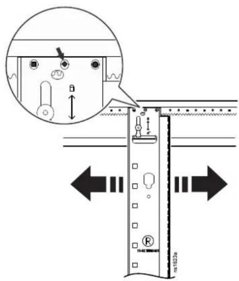
- When the vertical mounting flange is in the desired location at the top and bottom, raise the flat bracket to the lock position. The teeth in the bracket will engage fully with the teeth in the side place.
Tighten the TORX screw ^2
Install Equipment
▲WARNING
TIP HAZARD
- Make sure the cabinet is secured to the floor before installing equipment.
• Install the heaviest equipment first and toward the bottom of the cabinet to prevent the cabinet from becoming top-heavy. - Do not extend equipment on sliding rails until you have installed 158 kg (350 lb) of equipment into the bottom of the cabinet for stability or until you have installed the stabilizer plate or bolt-down brackets. Do not extend more than one piece of equipment on sliding rails at a time.
Failure to follow these instructions can result in death, serious injury, or equipment damage.
- Review the equipment manufacturer's installation instructions.
- Locate the top and bottom U-space on the vertical mounting rails. Every third hole on the mounting rails is numbered to indicate the middle of a U-space.
- Install the cage nuts on the interior of the vertical mounting rail; then install the equipment. (To remove a cage nut, squeeze the sides to release it from the square hole.)
Install a Cage Nut
APC by Schneider Electric offers a cage nut hardware kit (AR8100) for use with square holes.
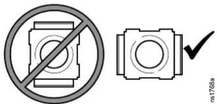
▲CAUTION
FALLING EQUIPMENT HAZARD
Install cage nuts horizontally, with the tabs engaging the left and right sides of the square hole. Do NOT install cage nuts vertically with the tabs engaging the top and bottom of the square hole.
Failure to follow these instructions can result in injury or equipment damage.
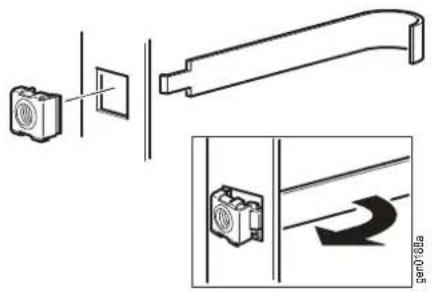
- Install the cage nuts on the interior of the vertical mounting flange. Insert the cage nut into the square hole by hooking one ear of the cage nut assembly through the far side of the hole.
- Place the cage nut tool on the other side of the cage nut and pull to snap it into position.
Remove a Cage Nut
- Remove any attached screw.
- Grasp the cage nut and squeeze the sides to release it from the square hole.
Cable Management
The NetShelter SX cabinet has multiple cable access openings, including on the roof, sides, and bottom. Route, secure, and organize cables using these openings. In addition, two rear vertical 0-U cable organizers, or accessory channels, are included with the cabinet. Further cable management accessories are available. See www.apc.com or contact your APC by Schneider Electric reseller for more information.
Accessory Channel
The accessory channels provide toolless mounting capabilities for Rack Power Distribution Units and cable management accessories.
There are two accessory channels included with the cabinet. The factory-default position for the accessory channels is in the rear of the cabinet.
The channels also provide tie-off locations for cables, as well as other specific holes for managing cables with many NetShelter brackets, fasteners, and toolless mounting equipment.
Similar to the mounting flanges, the accessory channel can be moved anywhere along the side braces. See Vertical Mounting Flanges, page 21 for more information.
NOTE: If needed, the accessory channels can be removed. Additional vertical 0-U accessory channels are available for order.
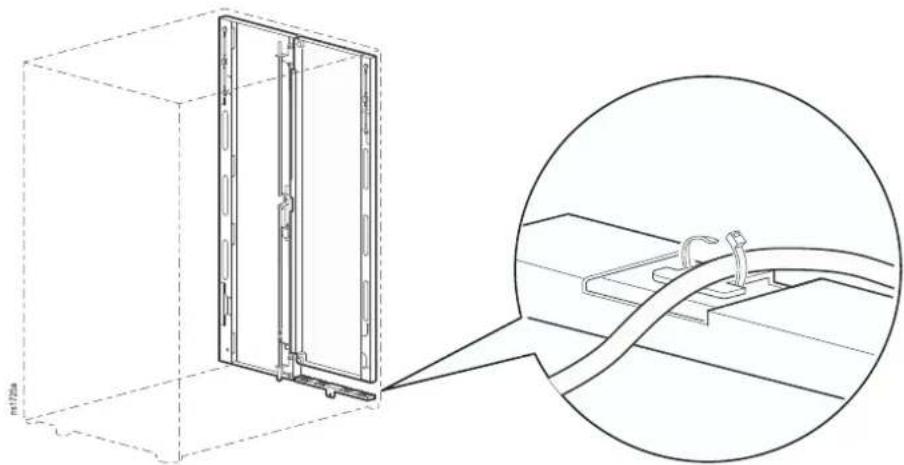
Rear-door Cable-containment Bracket
(AR3104/AR3104SP1 only)
The rear door cable containment bracket is installed within the cabinet under the left hand door. The bracket has 4 lobes for attaching cables with hook-and-loop fasteners (provided) and cable ties (not provided).
natural_image
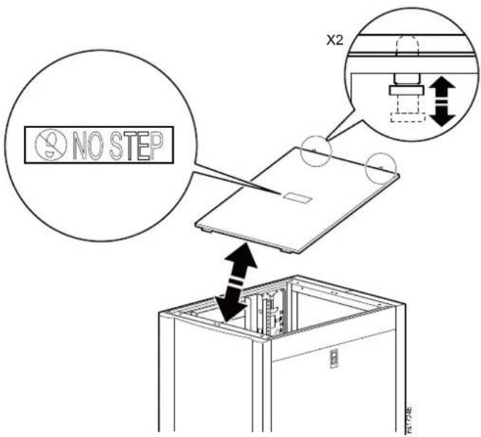
Technical line drawing of a 3D cabinet with an inset close-up showing internal components (no text or symbols)Specifications
| Measurement AR3003/AR3003SP AR3103/AR3103SP AR3006/AR3006SP AR3106/AR3106SP | AR3104/AR3104SP1 | |||||
| Height 658 mm (25.91 in) 658 mm (25.91 in) 925 mm (36.41 in) 925 mm (36.41 in) 1199 mm (47.20 in) | ||||||
| Width | 600 mm (23.62 in) | |||||
| Depth 900 mm (35.43 in) 1070 mm (42.13 in) 900 mm (35.43 in) 1070 mm (42.13 in) 1070 mm (42.13 in) | ||||||
| Net Weight 54 kg (119 lb) 59 kg (130 lb) 67 kg (148 lb) 72 kg (159 lb) 89 kg (196 lb) | ||||||
| Total open area(front door) | 178 727 m m^n (277.03 in) | 178 727 m m^n (277.03 in) | 262 212 m m^n (406.43 in) | 262 212 m m^n (406.43 in) | 345 808 m m^n (536.00 in) | |
| Total open area(rear door) | 199 552 m m^n (309.31 in) | 199 552 m m^n (309.31 in) | 293 917 m m^n (455.57 in) | 293 917 m m^n (455.57 in) | 375 870 m m^n (582.60 in) | |
| Open area per U(front door) | 14 894 m m^n (23.09 in) | 14 894 m m^n (23.09 in) | 14 567 m m^n (22.58 in) | 14 567 m m^n (22.58 in) | 14 406 m m^n (22.33 in) | |
| Open area per U(rear door) | 16 629 m m^n (25.78 in) | 16 629 m m^n (25.78 in) | 16 329 m m^n (25.31 in) | 163 29 m m^n (25.31 in) | 15 658 m m^n (24.27 in) | |
| Percent open (front) | 68% | 68% 69% 69% 67% | ||||
| Percent open (rear) | 76% | 76% 78% 78% 73% | ||||
| Clearance (for wiring between front door and vertical rail) | 60 mm (2.35 in) | 61 mm (2.40 in) 60 mm (2.35 in) 61 mm (2.40 in) 61 mm (2.40 in) | ||||
| Weight rating: static load* | 272 kg (600 lb) | 272 kg (600 lb) 408 kg (900 lb) 408 kg (900 lb) 1 361 kg (3,000 lb) | ||||
| Weight rating: rolling load | 272 kg (600 lb) | 272 kg (600 lb) 408 kg (900 lb) 408 kg (900 lb) 1 021 kg (2,250 lb) | ||||
| Weight rating: lifting load** | 272 kg (600 lb) | 272 kg (600 lb) 408 kg (900 lb) 408 kg (900 lb) 567 kg (1,250 lb) | ||||
| Weight rating: shipping load*** | 272 kg (600 lb) | 272 kg (600 lb) 408 kg (900 lb) 408 kg (900 lb) 1 021 kg (2,250 lb) | ||||
*Lower the leveling feet if the static weight is greater than 1020.58 kg (2,250 lb).
**Use rated M10 eye bolts to lift the cabinet. See Move the Cabinet, page 11 for more information.
***Applies only to cabinets with Shock Packaging (AR3003SP, AR3103SP, AR3006SP, AR3106SP, AR3104SP1)
NOTE: Shock packaging must be used if the rack is being reshipped with equipment installed. See the NetShelter SX product family page at www.apc.com for details on cabinets with shock packaging.
Five-year Factory Warranty
The limited warranty provided by APC by Schneider Electric in this Statement of Limited Factory Warranty applies only to products you purchase for your commercial or industrial use in the ordinary course of your business.
Terms of Warranty
APC by Schneider Electric warrants its products to be free from defects in materials and workmanship for a period of five years from the date of purchase. The obligation of APC by Schneider Electric under this warranty is limited to repairing or replacing, at its sole discretion, any such defective products. This warranty does not apply to equipment that has been damaged by accident, negligence, or misapplication or has been altered or modified in any way. Repair or replacement of a defective product or part thereof does not extend the original warranty period. Any parts furnished under this warranty may be new or factory-remanufactured.
Non-transferable Warranty
This warranty extends only to the original purchaser who must have properly registered the product. The product may be registered at www.apc.com.
Exclusions
APC by Schneider Electric by Schneider Electric shall not be liable under the warranty if its testing and examination disclose that the alleged defect in the product does not exist or was caused by end user's or any third person's misuse, negligence, improper installation or testing. Further, APC by Schneider Electric shall not be liable under the warranty for unauthorized attempts to repair or modify wrong or inadequate electrical voltage or connection, inappropriate on-site operation conditions, corrosive atmosphere, repair, installation, start-up by non-APC by Schneider Electric designated personnel, a change in location or operating use, exposure to the elements, Acts of God, fire, theft, or installation contrary to APC by Schneider Electric recommendations or specifications or in any event if the APC by Schneider Electric serial number has been altered, defaced, or removed, or any other cause beyond the range of the intended use.
THERE ARE NO WARRANTIES, EXPRESS OR IMPLIED, BY OPERATION OF LAW OR OTHERWISE, OF PRODUCTS SOLD, SERVICED OR FURNISHED UNDER THIS AGREEMENT OR IN CONNECTION HEREWITH. APC BY SCHNEIDER ELECTRIC DISCLAIMS ALL IMPLIED WARRANTIES OF MERCHANTABILITY, SATISFACTION AND FITNESS FOR A PARTICULAR PURPOSE. APC BY SCHNEIDER ELECTRIC EXPRESS WARRANTIES WILL NOT BE ENLARGED, DIMINISHED, OR AFFECTED BY AND NO OBLIGATION OR LIABILITY WILL ARISE OUT OF, APC BY SCHNEIDER ELECTRIC RENDERING OF TECHNICAL OR OTHER ADVICE OR SERVICE IN CONNECTION WITH THE PRODUCTS. THE FOREGOING WARRANTIES AND REMEDIES ARE EXCLUSIVE AND IN LIEU OF ALL OTHER WARRANTIES AND REMEDIES. THE WARRANTIES SET FORTH ABOVE CONSTITUTE APC BY SCHNEIDER ELECTRIC'S SOLE LIABILITY AND PURCHASER'S EXCLUSIVE REMEDY FOR ANY BREACH OF SUCH WARRANTIES. APC BY SCHNEIDER ELECTRIC WARRANTIES EXTEND ONLY TO PURCHASER AND ARE NOT EXTENDED TO ANY THIRD PARTIES.
IN NO EVENT SHALL APC BY SCHNEIDER ELECTRIC, ITS OFFICERS, DIRECTORS, AFFILIATES OR EMPLOYEES BE LIABLE FOR ANY FORM OF INDIRECT, SPECIAL, CONSEQUENTIAL OR PUNITIVE DAMAGES, ARISING OUT OF THE USE, SERVICE OR INSTALLATION, OF THE PRODUCTS, WHETHER SUCH DAMAGES ARISE IN CONTRACT OR TORT,
IRRESPECTIVE OF FAULT, NEGLIGENCE OR STRICT LIABILITY OR WHETHER APC BY SCHNEIDER ELECTRIC HAS BEEN ADVISED IN ADVANCE OF THE POSSIBLY OF SUCH DAMAGES. SPECIFICALLY, APC BY SCHNEIDER ELECTRIC IS NOT LIABLE FOR ANY COSTS, SUCH AS LOST PROFITS OR REVENUE, LOSS OF EQUIPMENT, LOSS OF USE OF EQUIPMENT, LOSS OF SOFTWARE, LOSS OF DATA, COSTS OF SUBSTITUENTS, CLAIMS BY THIRD PARTIES, OR OTHERWISE.
NO SALESMAN, EMPLOYEE OR AGENT OF APC BY SCHNEIDER ELECTRIC IS AUTHORIZED TO ADD TO OR VARY THE TERMS OF THIS WARRANTY. WARRANTY TERMS MAY BE MODIFIED, IF AT ALL, ONLY IN WRITING SIGNED BY AN APC BY SCHNEIDER ELECTRIC OFFICER AND LEGAL DEPARTMENT.
Warranty Claims
Customers with warranty claims issues may access the customer support network through the Support page, www.apc.com/support. Select your country from the country selection pull-down menu at the top of the Web page. Select the Support tab to obtain contact information for customer support in your region.
APC by Schneider Electric
132 West Fairgrounds Rd
02892 West Kingston, RI
USA
www.apc.com
As standards, specifications, and design change from time to time, please ask for confirmation of the information given in this publication.