X-01 - Treadmills LifeSpan - Free user manual and instructions
Find the device manual for free X-01 LifeSpan in PDF.

| Product Type | Elliptical Trainer |
| Brand | LifeSpan |
| Model | X-01 |
| Maximum User Weight | 120 kg (264.5 lbs) |
| Power Source | 2 x AA (1.5V) batteries |
| Monitor Functions | Time, Speed, Distance, Calories, Scan (cycle every 6 seconds) |
| Tension Adjustment | Manual knob, clockwise to increase, counterclockwise to decrease |
| Pedal Modes | Forward (quadriceps) and backward (hamstrings) movement |
| Handlebar Modes | Dual-action (moves with pedals) and fixed mode |
| Seat Adjustment | Height adjustable via tri-locking knob |
| Frame | Steel main frame with front and rear stabilizers |
| Pedals | Large non-slip pedals, left and right labeled |
| Handlebar Adjustment | Height adjustable with umbrella knobs |
| Transport Rollers | 2 front rollers for easy movement |
| Friction Belt | Adjustable for tension fine-tuning |
| Chain Drive | Chain and sprocket system with chain adjusting kit |
| Warranty | Refer to Australian Consumer Law; contact support@lifespanfitness.com.au |
| Intended Use | Indoor home use only |
| Maintenance | Lubricate moving joints regularly; clean with dry cloth |
| Battery Safety | Do not mix old/new or different types; remove when not in use |
Frequently Asked Questions - X-01 LifeSpan
User questions about X-01 LifeSpan
0 question about this device. Answer the ones you know or ask your own.
Ask a new question about this device
Download the instructions for your Treadmills in PDF format for free! Find your manual X-01 - LifeSpan and take your electronic device back in hand. On this page are published all the documents necessary for the use of your device. X-01 by LifeSpan.
USER MANUAL X-01 LifeSpan
natural_image
Line drawing of an exercise bike with dual-axis legs and control knobs (no text or symbols)
Product may vary slightly from the item pictured due to model upgrades
Read all instructions carefully before using this product. Retain this owner's manual for future reference.
TABLE OF CONTENTS
- IMPORTANT SAFETY INSTRUCTIONS 3
- CARE INSTRUCTIONS 4
- EXPLODED DIAGRAM 5
- PARTS LIST 6
- ASSEMBLY INSTRUCTIONS 7
- TENSION ADJUSTMENT 12
- EXERCISE MONITOR INSTRUCTIONS 14
- WARRANTY 16
1. IMPORTANT SAFETY INSTRUCTIONS
WARNING - Read all instructions before using this machine.
It is important your machine receives regular maintenance to prolong its useful life. Failing to regularly maintain your machine may void your warranty.
Please keep this manual with you at all times
a. It is important to read this entire manual before assembling and using the equipment. Safe and effective use can only be achieved if the equipment is assembled, maintained and used properly. Please note: It is your responsibility to ensure that all users of the equipment are informed of all warnings and precautions.
b. Before starting any exercise program you should consult your doctor to determine if you have any medical or physical conditions that could put your health and safety at risk, or prevent you from using the equipment properly. Your doctor's advice is essential if you are taking medication that affects your heart rate, blood pressure or cholesterol level.
c. Be aware of your body's signals. Incorrect or excessive exercise can damage your health. Stop exercising if you experience any of the following symptoms: pain, tightness in your chest, irregular heartbeat, and extreme shortness of breath, lightheadedness, dizziness or feelings of nausea. If you do experience any of these symptoms, you should consult your doctor before continuing with your exercise program.
d. Keep children and pets away from the equipment. This equipment is designed for adult use only.
e. Use the equipment on a solid, flat level surface with a protective cover for your floor or carpet. To ensure safety, the equipment should have at least 2 meters of free space around it.
f. Before using the equipment, check that the nuts and bolts are securely tightened. If you hear any unusual noises coming from the equipment during use and assembly, stop immediately. Do not use
the equipment until the problem has been rectified.
g. Wear suitable clothing while using the equipment. Avoid wearing loose clothing that may get caught in the equipment or that may restrict or prevent movement.
h. This equipment is designed for indoor and family use only
i. Care must be taken when lifting or moving the equipment so as not to injure your back.
j. Always keep this instruction manual and assembly tools at hand for reference.
k. The equipment is not suitable for therapeutic use.
2. CARE INSTRUCTIONS
a. Maximum use weight: 120KG
b. Lubricate moving joints with grease after periods of usage
c. Be careful not to damage plastic or metal parts of the machine with heavy or sharp objects
d. The machine can be kept clean by wiping it down using dry cloth
Battery Usage
a. Batteries are to be installed or replaced by adult only
b. Do not use rechargeable batteries. Do not mix different battery types. Do not mix old and new batteries. Do not mix alkaline, standard (Carbon-Zinc), or rechargeable (Nickel-Cadmium) batteries
c. Remove batteries when product is not in use
d. Remove exhausted batteries from product and dispose of in accordance with the manufacturer's recommendation
e. Do not attempt to recharge non-rechargeable batteries
f. Batteries are to be inserted with correct polarity
g. The supply terminals are not to be short-circuited
h. Do not dispose of batteries in fire, batteries may explode or leak
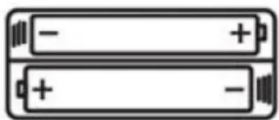
natural_image
Two stacked batteries with negative and positive charge indicators (no text or symbols)3. EXPLODED DIAGRAM
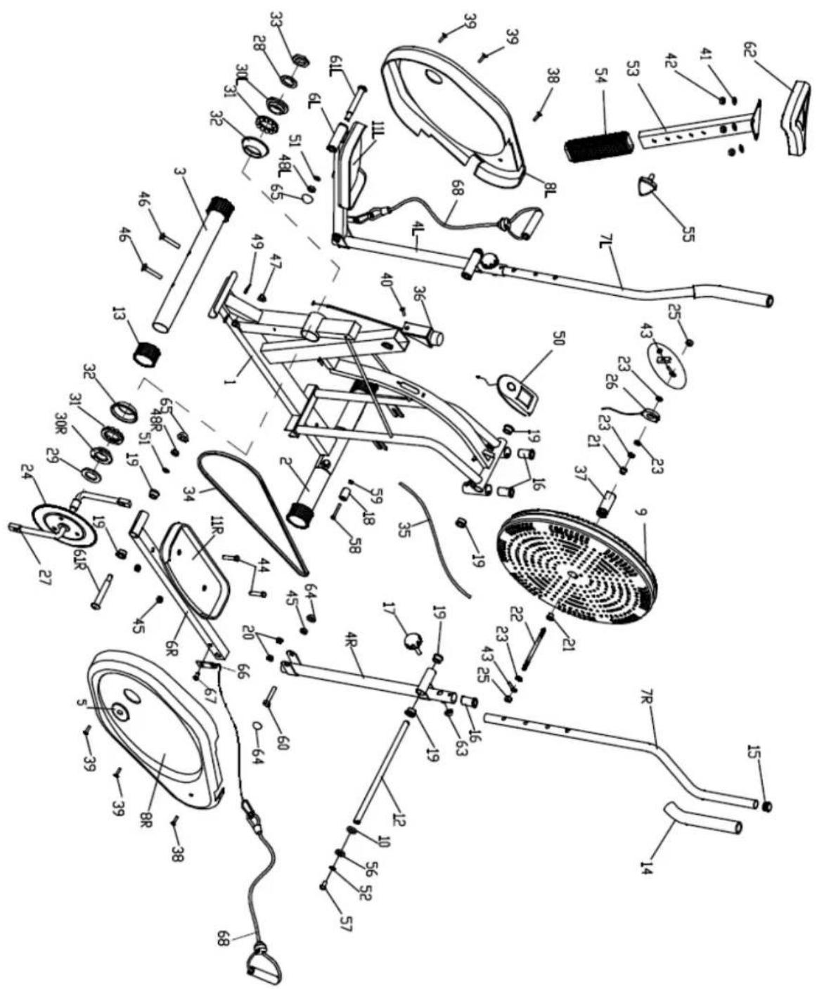
- PARTS LIST
| Parts No. | Description | Quantity | Parts No. | Description | Quantity |
| 1 | Main Frame | 1 | 35 | Friction Belt | 1 |
| 2 | Front Stabilizer | 1 | 36 | Tension Controller | 1 |
| 3 | Rear Stabilizer | 1 | 37 | Gear | 1 |
| 4 L/R | Rocking Arm | 1 each | 38 | Phillips Tapping Screw M5x15 | 2 |
| 5 | Plastic Seal Cover | 2 | 39 | Phillips Tapping Screw M5x45 | 7 |
| 6 L/R | Pedal Arm | 1 each | 40 | Countersunk Head Screw | 1 |
| 7 L/R | Handlebar | 1 each | 41 | Flat Washer | 3 |
| 8 L/R | Chain Cover | 1 pair | 42 | Nylon Nut | 3 |
| 9 | Fan Wheel | 1 | 43 | Chain Adjusting Kit | 2 |
| 10 | Flat Washer | 1 | 44 | Hex Bolt | 4 |
| 11 | Pedal | 2 | 45 | Nylon Nut | 6 |
| 12 | Handlebar Shaft | 1 | 46 | Carriage Bolt | 4 |
| 13 | Stabilizer End Cap | 4 | 47 | Acorn Nut | 4 |
| 14 | Foam Grip | 2 | 48 L/R | Nylon Nut | 2 |
| 15 | Round Cap φ1" | 6 | 49 | Arc Washer | 4 |
| 16 | Handlebar Bushing | 4 | 50 | Monitor | 1 |
| 17 | Umbrella Knob | 2 | 51 | Spring Washer | 2 |
| 18 | Transport Roller | 2 | 52 | Spring Washer 13φx8.5φx2.5 | 2 |
| 19 | Alloy Bushing φ5/8" | 10 | 53 | Seat Post | 1 |
| 20 | Alloy Bushing φ3/8" | 4 | 54 | Seat Post Sleeve | 1 |
| 21 | Brass Bushing | 2 | 55 | Tri-Locking Knob | 1 |
| 22 | Fan Wheel Axle | 1 | 56 | D-Shaped Washer | 2 |
| 23 | Hex Thin Nut | 4 | 57 | Allen Bolt | 2 |
| 24 | Sprocket | 1 | 58 | Hex Bolt | 2 |
| 25 | Flange Nut | 2 | 59 | Nylon Nut | 2 |
| 26 | Sensor | 1 | 60 | Hex Bolt | 2 |
| 27 | Crank | 1 | 61 L/R | Pedal Hinge Bolt | 1 pair |
| 28 | Washer | 1 | 62 | Saddle | 1 |
| 29 | Flat Washer | 1 | 63 | Nut Cap S13 | 2 |
| 30 L | 2-Slot Nut | 1 | 64 | Nut Cap S16 | 4 |
| 30 R | 3-Slot Nut | 1 | 65 | Nut Cap S18 | 2 |
| 31 | Collar Ball | 2 | 66 | Connecting plate | 2 |
| 32 | Collar Housing | 2 | 67 | Allen bolt | 2 |
| 33 | Hex Nut | 1 | 68 | Rope | 2 |
| 34 | Chain | 1 |
5. ASSEMBLY INSTRUCTIONS
NOTE:
Most of the listed assembly hardware has been packaged separately, but some hardware items have been preinstalled in the identified assembly parts. In these instances, simply remove and reinstall the hardware as assembly is required.
Please reference the individual assembly steps and make note of all preinstalled hardware.
STEP 1:
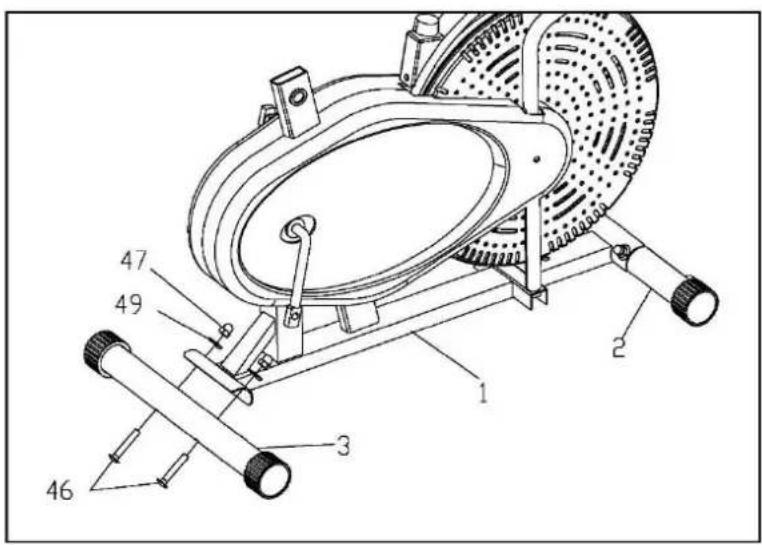
- Attach the Front Stabilizer (2) and the Rear Stabilizer (3) to the Main Frame (1), secured with the Carriage Bolts (46), Arc Washers (49), and Nylon Nuts (47) as shown.
STEP 2:
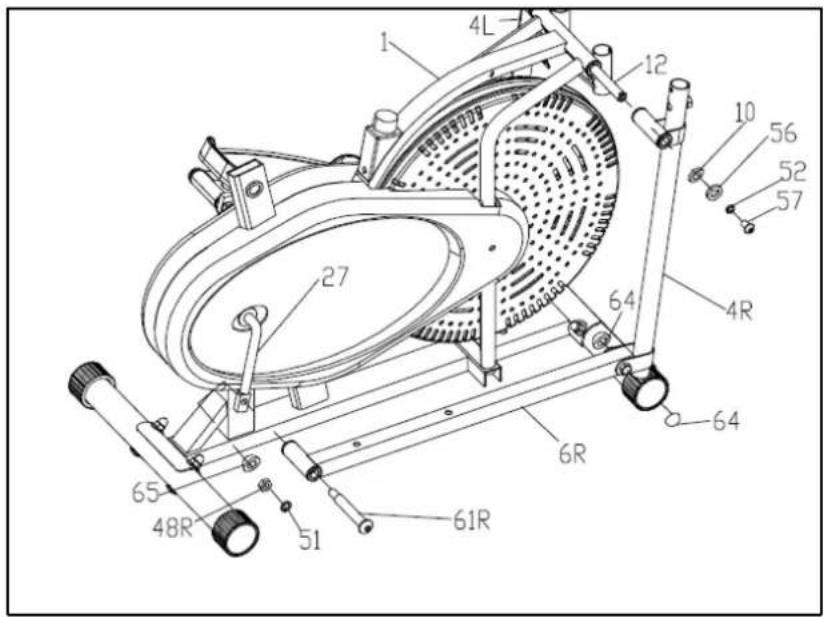
- Tighten Rocking Arm (4 L/R) to the Main Frame (1) with Handlebar Shaft (12), Allen Bolt (57), Spring Washer (52) and Flat Washer (10) as shown.
- Fit the Pedal Arms (6L/R) to the Crank (27), secured with the Pedal Hinge Bolts (61L/R), Spring Washers (51) and Nylon Nuts (48 L/R), and then cover the Nut Caps (65 & 64).
Note: Both Pedal Hinge Bolts are labeled L FOR LEFT and R FOR RIGHT.
To tighten turn the left bolt COUNTERCLOCKWISE and the right bolt CLOCKWISE.
Move the Crank to a proper angle for easily tightening the Bolts
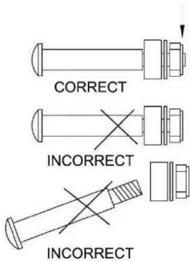
ATTENTION:
The Right and Left Hinge Bolt (No.61R/L) must fully penetrate the nylon ring inside the Pedal Arm Joint and the Crank. This will ensure the stability and durability of your Elliptical Trainer.
In order to install hinge bolt properly, keep it perfectly straight as the bolt goes through the pedal arms and the crankshaft. If the hinge bolt is connected to the crankshaft at an angle, damage to both the hinge and the crankshaft may occur.
STEP 3:
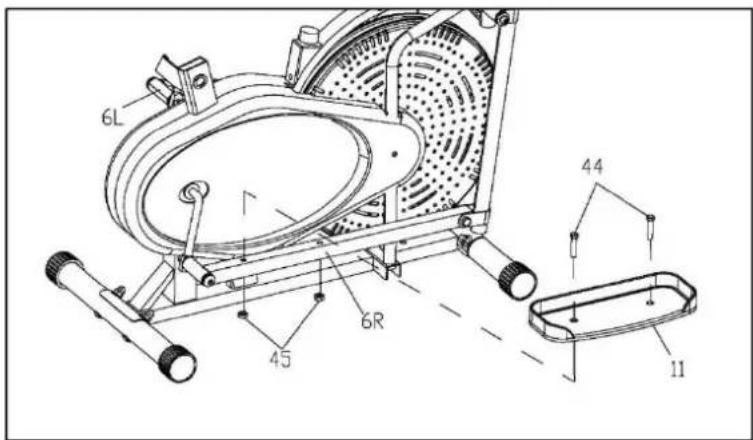
- Tighten the both sides of Pedal Hinge Bolts (61L/R) before assembling the pedals. Attach the Pedals (11) to their respective Pedal Arms (6L/R) using the Hex Bolts (44) and Nylon Nuts (45).
Note: Both Pedals are labelled L FOR LEFT and R FOR RIGHT.
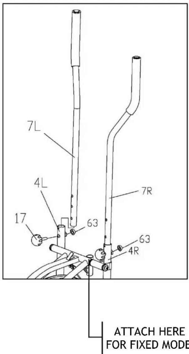
STEP 4:
-
Attach the Handlebar (7L/R) to the Rocking Arm (4L/R) respectively, select a height setting that is comfortable to the user and make sure both Handlebars are set at the same height.
-
Lock each Handlebar in place with Umbrella-Knobs (17), and then cover the Nut Caps (63) as shown.
Note: You can easily switch your Handlebars (7L/R) between the dual-action mode and the fixed mode during your workout.
DUAL ACTION MODE: To allow the handlebars to move along with the pedals.
FIXED MODE: To keep the handlebars stationary while you work out.
STEP 5:
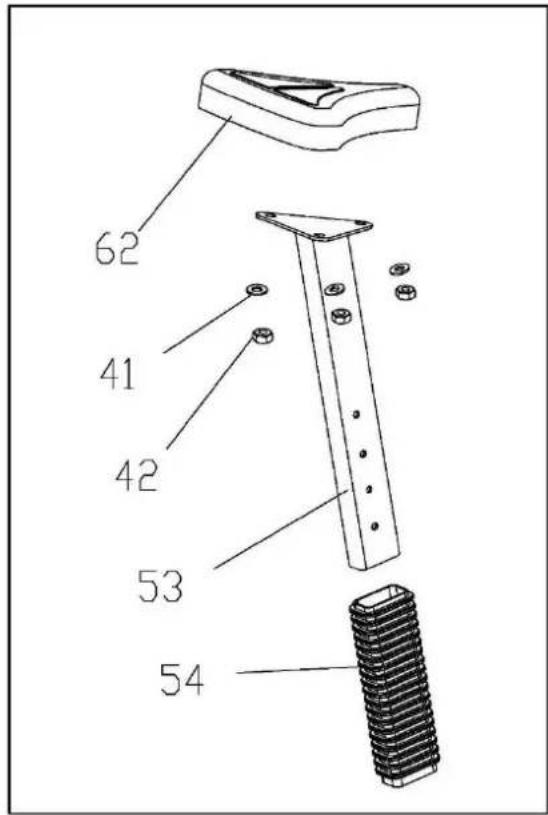
- Attach the Saddle (62) to the Seat Post (53) with Flat Washers (41) and Nylon Nuts (42) provided; Slide the Sleeve (54) onto the Seat Post (53).
STEP 6:
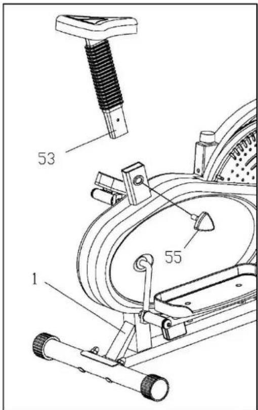
- Insert the Seat Post with Saddle into the Frame Section (1) and lock at desired height with Tri-Locking Knob (55).
STEP 7:
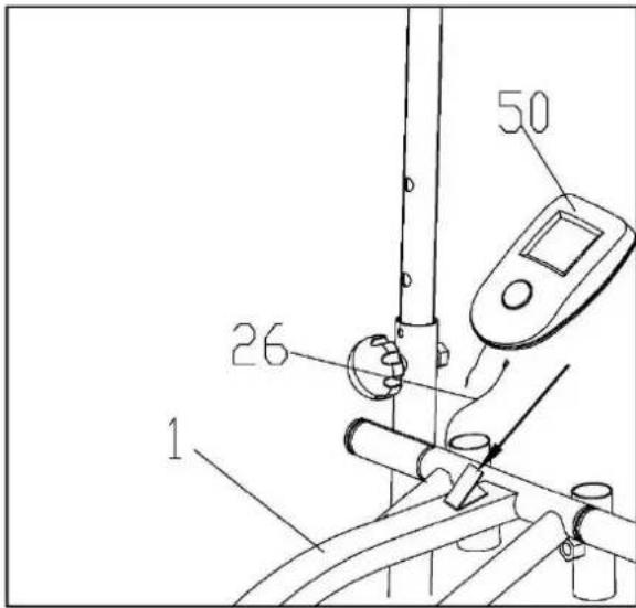
- Connect the Sensor Wire (26) to the Monitor (50), and then insert the Monitor onto the Bracket as shown.
STEP 8:
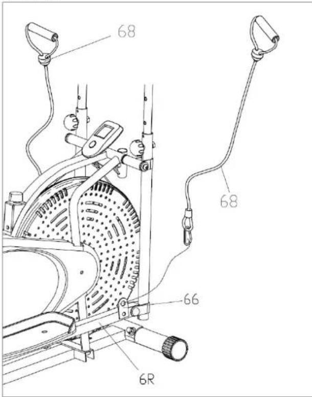
- Attach the Rope (68) to the connecting plate (66).
6. TENSION ADJUSTMENT
Tension adjustment
The assembly of your Elliptical Trainer is now complete. As you try your exercises for the first time, you should adjust the tension to the correct level before you begin your full workout. Turning the adjustment knob allows you to change the tension level and vary the intensity of your workout as you exercise.
To increase tension turn the tension knob to the clockwise and to decrease tension turn the tension knob counterclockwise.
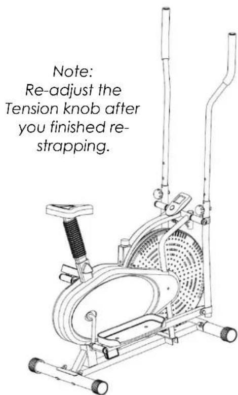
Adjusting the friction belt
You can loosen or tighten the friction belt for greater tension adjustment.
Turn the tension adjustment knob all the way to the loosest setting. Then re-strap the friction belt at the buckle in the main frame which just beneath the flat beam at the top centre. The more length you allow for the friction belt to wrap around the fan wheel. the less friction it will cause. Re-adjust the tension knob after you finished re-strapping

natural_image
Abstract black-and-white line drawing of a stylized letter 'R' with geometric shapes (no text or symbols)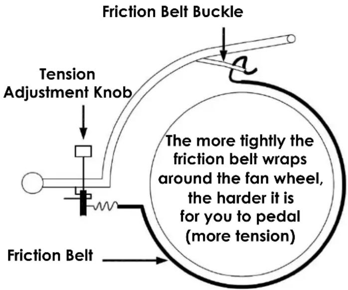
Reversible movement
Your Elliptical Trainer has REVERSIBLE movement!
Forward pedaling exercises your quadriceps (front thigh muscles), while backward pedaling targets your hamstrings (back thigh muscles). Take advantage of these facts to make your workout less fatiguing and more fun.
CAUTION: MAKE SURE YOU HAVE TIGHTENED ALL NUTS AND BOLTS BEFORE BEGINNING YOUR WORKOUT
7. EXERCISE MONITOR INSTRUCTIONS
EXERCISE MONITOR FUNCTIONS
Your Exercise Monitors will have SOME or ALL the following functions: -
CALORIES \~ (COMPUTED THEORETICAL CALORIE BURN)
DISTANCE \~ (EXERCISE DISTANCE [KM])
SCAN \~ (CHANGING FROM FUNCTION TO FUNCTION)
SPEED \~ (CYCLE SPEED [KM/H]
TIMER \~ (COUNT UP [minutes and seconds])
MONITOR FUNCTION SPECIFICATIONS
CALORIES 0.00 - 999.9 Kcal (THEORETICAL)
DISTANCE KM (COUNT UP)
SCAN CYCLES THROUGH EACH FUNCTION, SWITCHED EVERY 6 SECONDS
SPEED 0.00 - 99.9 KM/H
TIMER 0.00 - 99.59 MINUTES (COUNT UP)
MONITOR OPERATING SPECIFICATIONS
POWER SOURCE 2 x AA (1.5v) POWER CELLS
STORAGE TEMPERATURE -10c - +60c
NORMAL OPERATING TEMPERATURE 0c - +50c
USING YOUR EXERCISE MONITOR
To provide ease of use, there is only 1 button on your Exercise Monitor: - MODE
Press the MODE button to manually move through each of the Exercise Monitor's functions in turn. These are in order: - TIME, SPEED, DISTANCE and CALORIES. If you press the MODE button until you reach the SCAN mode and then release it, the display will change EVERY 6 SECONDS to show each function in turn.
Pressing and holding the MODE button when you are in any of the above functions will set to zero any previous figures remaining in each function.
Start to exercise and the Exercise Monitor will begin to register the various functions.
8. WARRANTY
AUSTRALIAN CONSUMER LAW
Many of our products come with a guarantee or warranty from the manufacturer. In addition, they come with guarantees that cannot be excluded under the Australian Consumer Law. You are entitled to a replacement or refund for a major failure and compensation for any other reasonably foreseeable loss or damage.
You are entitled to have the goods repaired or replaced if the goods fail to be of acceptable quality and the failure does not amount to a major failure. Full details of your consumer rights may be found at www.consumerlaw.gov.au
Please visit our website to view our full warranty terms and conditions:
http://www.lifespanfitness.com.au/warranty-repairs
Warranty and Support:
Please email us at support@lifespanfitness.com.au for all warranty or support issues.
For all warranty or support related enquiries an email must be sent before contacting us via any other means.
Head Office and Customer Service:
Global Fitness and Leisure Pty Ltd
17 Fordson Rd
Campbellfield
VIC, 3061
Australia
PH: 03 9357 2166
- TABLE OF CONTENTS
- IMPORTANT SAFETY INSTRUCTIONS
- WARNING - Read all instructions before using this machine.
- CARE INSTRUCTIONS
- Battery Usage
- EXPLODED DIAGRAM
- ASSEMBLY INSTRUCTIONS
- NOTE:
- STEP 1:
- STEP 2:
- ATTENTION:
- STEP 3:
- STEP 4:
- TENSION ADJUSTMENT
- Tension adjustment
- Adjusting the friction belt
- Reversible movement
- CAUTION: MAKE SURE YOU HAVE TIGHTENED ALL NUTS AND BOLTS BEFORE BEGINNING YOUR WORKOUT
- EXERCISE MONITOR INSTRUCTIONS
- EXERCISE MONITOR FUNCTIONS
- MONITOR FUNCTION SPECIFICATIONS
- MONITOR OPERATING SPECIFICATIONS
- USING YOUR EXERCISE MONITOR
- WARRANTY
- AUSTRALIAN CONSUMER LAW
- Warranty and Support:
- Head Office and Customer Service:
Brand : LifeSpan
Model : X-01
Category : Treadmills