UMX-TP-TX100R - Émetteur AV Lightware - Free user manual and instructions
Find the device manual for free UMX-TP-TX100R Lightware in PDF.

User questions about UMX-TP-TX100R Lightware
0 question about this device. Answer the ones you know or ask your own.
Ask a new question about this device
Download the instructions for your Émetteur AV in PDF format for free! Find your manual UMX-TP-TX100R - Lightware and take your electronic device back in hand. On this page are published all the documents necessary for the use of your device. UMX-TP-TX100R by Lightware.
USER MANUAL UMX-TP-TX100R Lightware
visual engineering LIGHTWARE
UMX-TP-TX100R
User's Manual
SAFETY INSTRUCTIONS
Class II apparatus construction.
The equipment should be operated only from the power source indicated on the product.
To disconnect the equipment safely from power, remove the power cord from the rear of the equipment, or from the power source. The MAINS plug is used as the disconnect device, the disconnect device shall remain readily operable.
There are no user-serviceable parts inside of the unit. Removal of the cover will expose dangerous voltages. To avoid personal injury, do not remove the cover. Do not operate the unit without the cover installed.
The apparatus shall not be exposed to dripping or splashing and that no objects filled with liquids, such as vases, shall be placed on the apparatus. No naked flame sources, such as lighted candles, should be placed on the apparatus.
The appliance must be safely connected to multimedia systems. Follow instructions described in this manual.
Ventilation
For the correct ventilation and avoid overheating ensure enough free space around the appliance. Do not cover the appliance, let the ventilation holes free and never block or bypass the ventilators (if any).
WARNING
To prevent injury, the apparatus is recommended to securely attach to the floor/wall or mount in accordance with the installation instructions.
WEEE ( Waste Electrical & Electronic Equipment )
Correct Disposal of This Product

natural_image
Pure electrical circuit lines without any symbolsThis marking shown on the product or its literature, indicates that it should not be disposed with other household wastes at the end of its working life. To prevent possible harm to the environment or human health from uncontrolled waste disposal, please separate this from other types of wastes and recycle it responsibly to promote the sustainable reuse of material resources.
Household users should contact either the retailer where they purchased this product, or their local government office, for details of where and how they can take this item for environmentally safe recycling.
Business users should contact their supplier and check the terms and conditions of the purchase contract. This product should not be mixed with other commercial wastes for disposal.
Table of contents
1. INTRODUCTION......8
2. GENERAL DESCRIPTION......8
2.1. BOX CONTENTS....8
2.2 FEATURES 8
2.3. TYPICAL APPLICATIONS.... 10
2.4. UNDERSTANDING EDID....11
2.4.1. Basics 11
2.4.2. Common problems related to EDID....11
2.5. ADVANCED EDID MANAGEMENT 12
2.6. HDCP MANAGEMENT 12
2.6.1. HDPC key caching.... 12
2.6.2. Avoiding unnecessary HDCP encryption.... 12
2.7. PIXEL ACCURATE RECLOCKING....14
3. CONTROLS AND CONNECTIONS .... 15
3.1. UMX-TP-TX100R FRONT VIEW.... 15
3.2. UMX-TP-TX100R REAR VIEW.... 16
4. ELECTRICAL CONNECTIONS.... 17
4.1. HDMI INPUT 17
4.2. VGA INPUT 17
4.3. DIGITAL AUDIO INPUT CONNECTOR 18
4.4. ANALOG STEREO AUDIO INPUT CONNECTORS.... 18
4.5. TWISTED PAIR OUTPUTS.... 19
4.6. RS-232 PORT 20
5. INSTALLATION....21
5.1. MOUNTING OF UMX-TP-TX100R....21
5.1.1. Rack shelf 21
5.1.2. Under desk mounting kit double 21
5.2. MAXIMUM TWISTED PAIR DISTANCES.... 21
5.3. ABOUT SERIAL DEVICES.... 22
5.3.1. General information about serial communication 22
5.3.2. Type of serial cables 22
5.3.3. Example connection diagrams.... 22
5.4. CONNECTING SERIAL DEVICES 23
5.5. OPERATION MODES 24
5.5.1. Control mode 24
5.5.2. Pass-through mode 24
5.5.3. Changing the working mode 25
5.5.4. Detailed example: 25
5.6. POWERING DEVICE....26
5.6.1. Boot up of HDMI-TP extender units 27
6. OPERATION OF UMX-TP-TX100R 28
6.1. FRONT PANEL LEDs....28
6.2. INPUT SELECTION.... 29
6.2.1. VIDEO INPUT selection.... 29
6.2.2. AUDIO INPUT selection 29
6.2.3. AUTOSELECT mode 30
6.2.4. Audio input in AUTOSELECT mode 31
6.3. ABOUT EDID MEMORY 32
6.3.1. EDIDs are referred with Lightware Matrix Controller 32
6.3.2. EDIDs are referred with rotary switches 33
6.3.3. The assigning table.... 33
6.4. EDID TYPES 34
6.4.1. Factory preset EDID list.... 34
6.5. LEARNING THE EDID 35
6.6. SWITCHING THE EDID 35
6.7. DELETING THE EDID 36
6.8. INVALID EDID ON ANY INPUT 36
6.9. HDCP MANAGEMENT 36
6.10. No SYNC COLOR 37
6.11. HARDWARE RESET 37
6.12. RELOAD FACTORY DEFAULTS 37
7. SOFTWARE CONTROL – USING THE LIGHTWARE MATRIX CONTROLLER.... 38
7.1. INSTALLING THE MATRIX CONTROLLER SOFTWARE.... 38
7.2. ESTABLISHING THE CONNECTION.... 39
7.3. CONTROL MENU 41
7.3.1. Switch 41
7.3.2. Toggle between the working modes 41
7.3.3. Input parameter settings 41
7.3.4. Output parameter settings 46
7.4. EDID MENU 46
7.4.1. EDID Router operation 46
7.4.2. Advanced EDID Editor 48
7.4.3. Easy EDID Creator 49
7.5. TERMINAL MENU 49
7.6. STATUS MENU 50
7.6.1. Generate report file 50
7.6.2. Browse command file 51
7.7. FIND MENU 51
8. PROGRAMMERS REFERENCE....52
8.1. SERIAL PORT SETTINGS 52
8.2. PROTOCOL DESCRIPTION....52
8.3. STATUS AND IDENTIFICATION COMMANDS 54
8.3.1. View product type 54
8.3.2. View serial number 54
8.3.3. View Firmware version of the CPU 54
8.3.4. View installed controllers' firmware.... 54
8.3.5. View device's temperature.... 54
8.3.6. View CPU firmware compile time 55
8.3.7. View installed I/O boards 55
8.4. SYSTEM COMMANDS....55
8.4.1. Query current control protocol 55
8.4.2. Change RS-232 baud rate 56
8.4.3. Query RS-232 baud rate.... 56
8.4.4. Reload factory defaults 56
8.4.5. Set the RS-232 operation mode 57
8.4.6. Query the RS-232 operation mode 57
8.4.7. Count HDCP keys.... 57
8.4.8. Clear HDCP key cache 58
8.4.9. Restart matrix router 58
8.4.10. View error list 58
8.4.11. Configure remote alerts 59
8.4.12. Query level of remote alerts.... 59
8.4.13. Set the priority settings 59
8.4.14. Query the priority settings....60
8.5. EDID ROUTER COMMANDS 60
8.5.1. Save EDID to user memory (Learn EDID)....60
8.5.2. View emulated EDIDs on all inputs.... 60
8.5.3. Watch EDID validity table 61
8.5.4. View EDID header 61
8.5.5. Download EDID content from the router 62
8.5.6. Upload EDID content to the router 62
8.5.7. Delete EDID from memory....63
8.6. CONTROL COMMANDS 63
8.6.1. Switch one input to one output 64
8.6.2. View video connection on the output 64
8.6.3. View all connections on the output 64
8.6.4. Rename an input 65
8.6.5. Rename the output 65
8.6.6. Read an input's name 65
8.6.7. Read the output's name.... 65
8.6.8. Reload default input names 65
8.6.9. Reload default output name.... 66
8.7. PORT STATUS COMMANDS 66
8.7.1. Input port status 66
8.7.2. Output port status 66
8.7.3. All port status 66
8.8. INPUT PROPERTIES....67
8.8.1. Set input port properties 67
8.8.2. Query input port properties 69
8.8.3. Set analog timing properties 70
8.8.4. Query analog timing properties.... 70
8.8.5. Reset analog timing properties 70
8.8.6. Set analog color properties....71
8.8.7. Save analog color properties 71
8.8.8. Query analog color properties 72
8.8.9. Reset analog color properties....72
8.8.10. Set analog input audio parameters....72
8.8.11. Query analog input audio properties 73
8.8.12. Set the color of no sync picture 73
8.8.13. Query the color of no sync picture 73
8.8.14. Query timings of the incoming signal.... 74
8.8.15. Save preset....74
8.8.16. Delete preset....74
8.8.17. Delete all presets 75
8.8.18. Clone preset....75
8.8.19. List presets....75
8.8.20. Delete preset from all input ports.... 76
8.9. OUTPUT PROPERTIES 76
8.9.1. Set output video properties....76
8.9.2. Query output video properties 78
8.10. ERROR RESPONSES 78
9. COMMANDS – QUICK SUMMARY ...... 79
10. FIRMWARE UPGRADE 82
10.1. SHORT INSTRUCTIONS....82
10.2. DETAILED INSTRUCTIONS....82
10.2.1. Installing and launching the Bootloader software 82
10.2.2. Tips for the upgrade process....84
10.2.3. Firmware upgrade 84
10.3. FORCED FIRMWARE UPGRADE 87
11. TROUBLESHOOTING 88
12. SPECIFICATIONS....89
13. MECHANICAL DRAWINGS....93
14. VERSION APPLICABILITY....94
15. WARRANTY 94
16. DOCUMENT REVISION HISTORY 94
1. Introduction
Dear Customer,
Thank you for choosing Lightware UMX-TP-TX100R monitor extender.
Lightware's UMX-TP-TX100R is an all-round, universal video and audio transmitter for ever-changing environments such as small board rooms and classrooms. The extender was designed to handle digital and analog video and audio signals e.g. VGA, YPbPr, DVI and HDMI 1.3 with analog stereo, 5.1 S/PDIF and even 7.1 HDMI embedded audio.
2. General description
2.1. Box contents
- UMX-TP-TX100R unit
- Quick Start Guide
- User's manual (this document)
- +12V DC wall plug adaptor
2.2. Features
- Advanced EDID Management – The user can emulate any EDID at the extender's inputs independently, read out and store the attached monitor's EDID in the internal memory locations, upload and download EDID files using Matrix Control Software.
- 2.25 Gb/s channel transmission – Extend any VGA or HDMI signal between 25 and 225 MHz pixel clock frequency conforming to DVI 1.0 and HDMI1.3 standards.
- Supports all HDTV resolutions – 720p, 1080i, 1080p 2K etc. HDTV signals up to 225 MHz pixel clock frequency are passed through regardless of the resolution.
- Control by front and rear panel buttons – Video and audio source select and EDID address selection with two decimal rotary switches and LEARN EDID button are available for Advanced EDID Management and control the device.
- RS-232 control – Simple ASCII based RS-232 protocol is used for switching, status request, etc.
- Bi-directional RS-232 pass-through – AV systems can contain serial port controllers and controlled devices. Serial port pass-through supports any unit that works with standard RS-232.
- Cross compatibility with any Lightware Twisted Pair device – All devices in the product series are cross compatible thanks to Lightware's attentive design. The transmitter can be paired with any receiver without restriction. With Lightware's hybrid modular matrix concept, it is even possible to connect the extender box directly to the matrix router using an MX-HDMI-TP-IB or MX-DVI-TP-IB+ input boards.
- Universal power adaptor – UMX-TP-TX100R transmitter is equipped with a universal +12V DC power adaptor, which accepts AC voltages from 100 to 240 Volts with 50 or 60 Hz line frequency.
-
Locking DC connector – Special plug of wall adaptor ensures safe power supply. This type of connector prevents unwanted extractions.
-
HDCP compliant – UMX-TP-TX100R complies with HDCP standard. Lightware is a legal HDCP adopter. Both HDCP encrypted and non-HDCP components can be installed in the same system. The included advanced HDCP management eliminates the need for re-authentication upon switching.
- 30 meter input cable compensation – Using 22AWG high quality DVI or HDMI cable, the digital inputs are automatically compensated for up to 30 meter cable length at 24bpp, which extends installation possibilities even at the highest HDTV or computer resolutions.
- Pixel Accurate Reclocking – (removes jitter caused by long cables) The output has a clean, jitter free signal, eliminating signal instability and distortion caused by long cables or connector reflections.
- Frame detector and signal analysis – Using the Lightware Matrix Controller software the exact video and audio signal format can be determined such as timing, frequencies, scan mode, HDCP encryption, color range, color space and audio sample rate.
- Deep Color support and conversion – It is possible to transmit the highest quality 36-bit video streams for perfect color reproduction.
- DVI/HDMI conversion – The router is able to convert from HDMI to DVI signals so that you can watch HDMI videos on your computer display without audio.
- Zero frame delay – Even on Analog Inputs - Lightware's UMX-TP-TX100R add no frame noticeable delay to the switched signal. There is no frame or line period delays to the signals when passing a Lightware device.
- Separate Audio and Video switching – Video and audio signals are separated and can be switched independently. Even if the HDMI stream contains embedded audio.
- Analog Audio and Video A/D conversion – UMX-TP-TX100R converts uncompressed analog audio and video signal to digital and places it to the output.
- Rack mounting options – Several mounting methods ensure universal usage. Units can be placed into standard racks or under flat surfaces.
- Input (video & audio) status LEDs – Front panel LEDs give feedback about state of the unit and the video and audio signals.
- Accepts analog and digital audio signals - Accepts analog stereo; 5.1 S/PDIF and even 7.1 HDMI embedded audio signals. Analog signals are converted to digital formats and digital or digitized analog audio can be embedded in the video stream.
- Autoswitch function for video and audio inputs – Autoselect mode with or without priority can toggles between inputs. It helps the handling of the transmitter and installation of new devices.
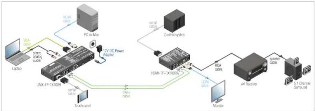
2.3. Typical applications
Some typical connection variations with the signal extender are shown on Figure 2-1 and Figure 2-2.
flowchart
graph TD
    A["Laptop"] -->|VCA cable| B["stereo analog audio"]
    B --> C["UMX-TP-TX100R"]
    C --> D["serial cable"]
    D --> E["Touch panel"]
    E --> F["12V DC Power Adaptor"]
    F --> G["PC or Mac"]
    G --> H["HDMI cable"]
    H --> I["control system"]
    I --> J["HDMI-TP-RX10DRA"]
    J --> K["RAM cable"]
    K --> L["Monitor"]
    L --> M["AV Receiver"]
    M --> N["speaker cable"]
    N --> O["5.1 Channel Surround"]
    J --> P["serial cable"]
Figure 2-1. Typical stand-alone application for UMX-TP-TX100R
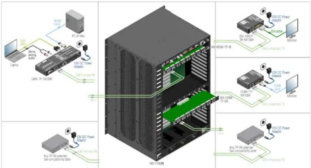
Figure 2-2. Integrated system application for UMX-TP-TX100R
Info: For the compatible Lightware products please see the compatibility table at www.lightware.com.
Application examples
- Small classrooms
– Conference rooms, collaborative telepresence - Control room
- Home cinema
2.4. Understanding EDID
2.4.1. Basics
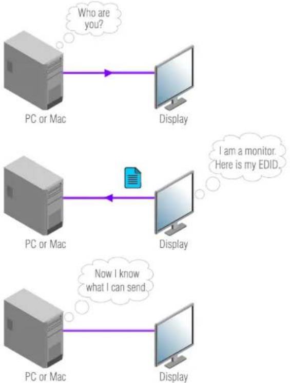
EDID stands for Extended Display Identification Data. Simply put, EDID is the passport of display devices (monitors, TV sets, projectors). It contains information about the display's capabilities, such as supported resolutions, refresh rates (these are called Detailed Timings), the type and manufacturer of the display device, etc.
After connecting a DVI source to a DVI display, the source reads out the EDID to determine the resolution and refresh rate of the image to be transmitted.
flowchart
graph TD
    A["PC or Mac"] -->|Who are you?| B["Display"]
    C["PC or Mac"] -->|I am a monitor. Here is my EDID.| D["Display"]
    E["PC or Mac"] -->|Now I know what I can send.| F["Display"]
Figure 2-3. EDID communication
Most DVI computer displays have 128-byte long EDID structure. However, Digital Televisions and HDMI capable displays may have another 128 bytes, which is called E-EDID and defined by CEA (Consumer Electronics Association). This extension contains information about additional Detailed Timings, audio capabilities, speaker allocation and HDMI capabilities. It is important to know, that all HDMI capable devices must have CEA extension, but not all devices are HDMI capable which have the extension.
2.4.2. Common problems related to EDID
Problem: "I have changed to a different EDID on an input port of the matrix to have a different resolution but nothing happens."
Solution: Some graphics cards and video sources read out the EDID only after power-up and later they don't sense that EDID has been changed. You need to restart your source to make it read out the EDID again.
Problem: "I have a UMX-TP-TX100R and I'm using a Lightware factory preset EDID. I would like to be able to choose from different resolutions, but my source allows only one resolution."
Solution: Most Lightware factory preset EDIDs allow only one resolution, forcing the sources to output only that particular signal. You need to select a Universal EDID. It supports all common VESA resolutions. Additionally it also features audio support.
2.5. Advanced EDID Management
Each DVI sink (e.g. monitors, projectors, plasma displays, and switcher inputs) must support the EDID data structure. Source BIOS and operating systems are likely to query the sink using DDC2B protocol to determine what pixel formats and interface are supported. HDMI standard makes use of EDID data structure for the identification of the monitor type and capabilities. Most DVI sources (graphic cards, set top boxes, etc.) will output DVI signal after accepting the connected sink's EDID information. In case of EDID readout failure or missing EDID the source will not output DVI video signal. UMX-TP-TX100R provides Lightware's Advanced EDID Management function that helps system integration. The built in EDID Router stores and emulates 18 EDID data plus all monitor's EDID that are connected to the output connectors. There are 10 factory preset and 8 user programmable EDIDs. The router stores the EDID of all attached monitors or projectors for the output in a non-volatile memory. This way the EDID from a monitor is available when the monitor is unplugged, or switched off.
Any EDID can be emulated on any input. An emulated EDID can be copied from the EDID router's memory (static EDID emulation), or from the last attached monitors memory (dynamic EDID emulation). For example, the router can be set up to emulate a device, which is connected to the output. In this case the EDID automatically changes, if the monitor is replaced with another display device (as long as it has a valid EDID).
EDID is independently programmable for all inputs without affecting each other. All inputs have their own EDID circuit. EDID Router can be controlled via serial port.
Info: The user is not required to disconnect the HDMI cable to change an EDID as opposed to other manufacturer's products. EDID can be changed even if a source is connected to the input and it is powered ON.
Info: When EDID has been changed, the unit toggles the HOTPLUG signal for 2 seconds. Some sources do not observe this signal, so in this case the change is not recognized by the source. In such cases the source device must be restarted or powered OFF and ON again.
2.6. HDCP management
Lightware Visual Engineering is a legal HDCP adopter, and has developed several functions that helps to solve HDCP related problems.
2.6.1. HDPC key caching
Lightware introduced the HDCP key cashing technique in early 2009 that validates all the display keys in an AV system during system boot up and keeps them constantly available for sources. This method eliminates the HDCP handshake at every switch and keeps all sources sending uninterrupted signals.
Without this function the sources should re-authenticate HDCP after each crosspoint switch which makes the displays to drop the signal and go black for 5-8 seconds. The HDCP key cashing technique avoids this and allows instantaneous switching between two encrypted signals.
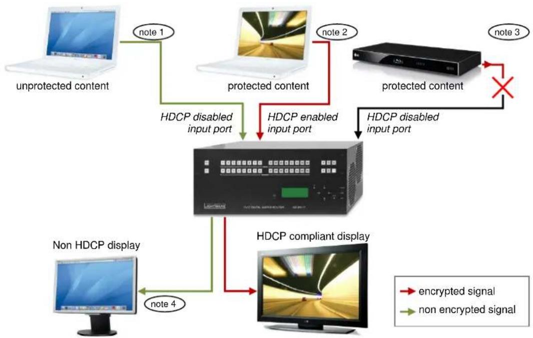
2.6.2. Avoiding unnecessary HDCP encryption
Many video sources send HDCP protected signal if they detect that the sink is HDCP capable – even if the content is not copyrighted. This can cause trouble if a HDCP capable device (e.g. repeater or matrix router) is connected between the source and the display. In this case the content can't be viewed on non-HDCP capable displays and interfaces like event controllers.
Rental and staging technicians often complain about Apple laptops, who always send HDCP encrypted signals if the receiver device (display, matrix router, etc.) reports HDCP compliancy. However HDCP encryption is not required all the time (e.g. computer desktop image) MacBook and MacBookPro still do that.

flowchart
graph LR
    A["unprotected content"] -->|encrypted signal| B["HDCP compliant repeater"]
    B --> C["×"]
    C --> D["Non HDCP display"]
    style A fill:#f9f,stroke:#333
    style D fill:#ccf,stroke:#333
To avoid unnecessary HDCP encryption, Lightware introduced the HDCP enabling/disabling function: the HDCP capability can be disabled on each input port separately. If HDCP is disabled on an input port, the connected source will detect that the sink is not HDCP capable, and turn off authentication. The source will not be able to communicate with any of the devices (displays, repeaters, etc.) that are connected to the routers output, therefore it could not see if they are HDCP capable or not.
flowchart
graph TD
    A["unprotected content"] -->|note 1| B["HDCP disabled input port"]
    C["protected content"] -->|note 2| D["HDCP enabled input port"]
    E["protected content"] -->|note 3| F["HDCP disabled input port"]
    G["non HDCP display"] -->|note 4| H["HDCP compliant display"]
    B --> I["Computer monitor"]
    D --> I
    F --> I
    H --> I
    style I fill:#f9f,stroke:#333,stroke-width:2px
    note1["Note 1"] --> B
    note2["Note 2"] --> D
    note3["Note 3"] --> F
    note4["Note 4"] --> H
    note5["Note 4"] --> G
    note6["Note 4"] --> H
    note7["Note 4"] --> I
    note8["Note 4"] --> H
    note9["Note 4"] --> I
    note10["Note 1"] --> B
    note11["Note 2"] --> D
    note12["Note 3"] --> F
    note13["Note 4"] --> H
Note 1: If a source detects that the input port is HDCP disabled, it will send only unprotected content.
Note 2: If a source detects that the input port is HDCP enabled, it could send protected or unprotected contents as well.
Note 3: HDCP protected content will not be sent to any input port with disabled HDCP setting.
Note 4: HDCP protected content will never be sent to a non HDCP compliant display.
Please note that if HDCP capability is disabled on an input port, the connected source cannot send protected content to any display. If HDCP function is enabled on an input port and the source sends encrypted signal, the non-HDCP compliant devices cannot display the video. This new feature does not remove the encryption of an encrypted signal, and does not void HDCP standard at all.
2.7. Pixel Accurate Reclocking
Signal reclocking is an essential important procedure in digital signal transmission. After passing the reclocking circuit, the signal becomes stable and jitter-free, and can be transmitted over more equipment like processors, or event controllers. Without reclocking, sparkles, noise and jaggies can be seen on the image.
Lightware's sophisticated Pixel Accurate Reclocking technology fixes more problems than general TMDS reclocking. It removes not only intra-pair skew but inter-pair skew as well.
The Pixel Accurate Reclocking circuit eliminates the following errors:
Intra-pair skew: skew between the + and - wires within a differential wire pair (e.g. Data2- and Data2+). It's caused by different wire lengths or slightly different wire construction (impedance mismatch) in HDMI cable. It results in jitter.
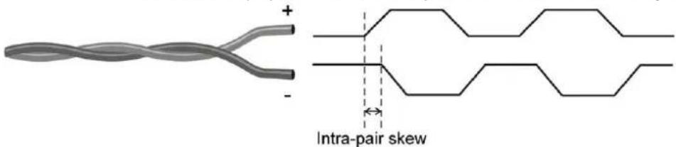
Inter-pair skew: skew between two differential wire pairs in a cable. It's caused by different wire pair lengths or different number of twists in the HDMI cable. Too much inter-pair skew results in color shift in the picture or sync loss.
Jitter: signal instability in the time domain. The time difference between two signal transitions should be a fix value, but noise and other effects cause variations.

Noise: electromagnetic interference between other electronic devices such as mobile phones, motors, etc. and the HDMI cable are coupled onto the signal. Too much noise results in increased jitter.

The Pixel Accurate Reclocking circuit completely regenerates the original video signal and outputs a strong, high-quality digital signal that conforms to the HDMI specification.
3. Controls and connections
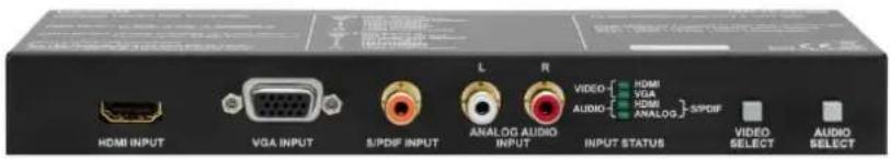
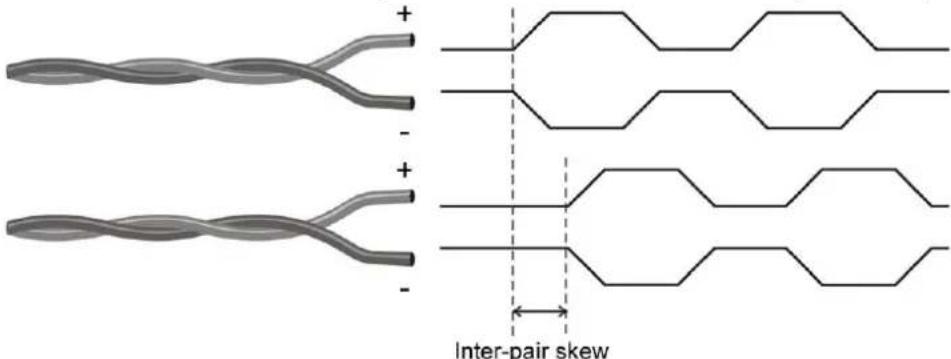
3.1. UMX-TP-TX100R front view
Figure 3-1. UMX-TP-TX100R front view
1 HDMI input Connect one HDMI cable between the HDMI source and the transmitter unit. For more information see chapter 4.1 on page 17.
2 VGA input Connect one VGA cable between the analog video source and the transmitter unit. For more information see chapter 4.2 on page 17.
3 S/PDIF input RCA jack connector with S/PDIF digital audio signal. For more information see chapter 4.3 on page 18.
4 Analog audio input Double RCA jack connector for analog stereo audio input signal with right and left channel. For more information see section 4.4 on page 18.
5 Status LEDs The LEDs give feedback about state of the unit and the video and audio signals. For more information about names and meanings of the Status LEDs see chapter 6.1 on page 28.
6 VIDEO select Switching between video inputs (HDMI / VGA / Autoselect) is available with the VIDEO select button. For more information see section 6.2.1 on page 29.
7 AUDIO select Switching between audio inputs (HDMI / ANALOG / S/PDIF) is available with the AUDIO select button. For more information see section 6.2.2 on page 29.
3.2. UMX-TP-TX100R rear view
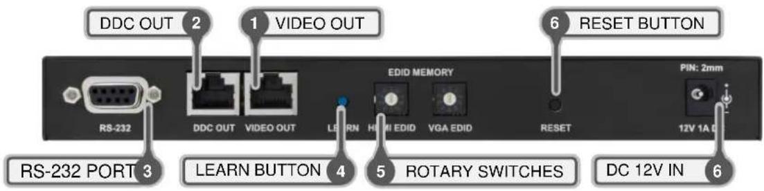
Figure 3-2. UMX-TP-TX100R rear view
| 1 | VIDEO OUT Connect a Twisted Pair cable (CAT7 recommended) between the VIDEO OUT of the transmitter unit and the VIDEO IN of the receiver unit. (e.g. HDMI-TP-RX100RA or a Lightware Hybrid Matrix equipped with twisted pair input cards). For more information see chapter 4.5 on page 19. | |
| 2 | DDC OUT Connect a Twisted Pair cable (CAT7 recommended) between DDC OUT of the transmitter unit and the DDC IN of the receiver unit (e.g. HDMI-TP-RX100RA or a Lightware Hybrid Matrix equipped with twisted pair input cards). For more information see chapter 4.5 on page 19. | |
| 3 | RS-232 port | 9-pole D-sub female connector for standard RS-232 port. Connect a serial cable between the transmitter unit and the serial device. RS-232 pass-through, Advanced EDID management and firmware upgrades are available via the RS-232 interface. For more information see chapters 4.6 and 5.3 - 5.5.4 on pages 20 and 22 - 25. |
| 4 | LEARN button | Stores the EDID of the display device attached to receiver device's video output in the selected memory address between #6...#9. To learn the EDID, select an appropriate address with the rotary switches and press and hold the Learn button for two seconds. For more information see chapter 6.5 on page 35. |
| 5 | Rotary switches | The rotary switch selects one of 9 addresses on both input port. EDID memories #1 .. #5 contain factory presets and #6 .. #9 are user programmable. Address #0 enable dynamic EDID emulation which copies EDID from receiver device's video output. For more information see chapter 6.6 on page 35. Use a flat head screwdriver that fits into the actuator. Avoid the use of keys, coins, knives and other sharp objects because they might cause permanent damage to the rotary switches. |
| 6 | Reset button | Hardware reset button. It resets the whole device, however saved settings and EDIDs will be preserved. |
| 7 | DC 12V in | Connect the output of the supplied +12V DC power adaptor. CAUTION! Warranty void if damage occurs due to use of a different power source. |
Info: The UMX-TP-TX100R does not have networking capabilities. Do not connect the RJ45 output(s) of the UMX-TP-TX100R to a Local Area Network device or a PC. Doing so may damage the unit!
4. Electrical connections
4.1. HDMI Input
UMX-TP-TX100R provides standard 19 pole HDMI connector for inputs. Always use high quality HDMI cable for connecting sources and displays.
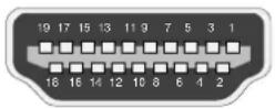
HDMI Type A receptacle
| Pin | Signal | Pin | Signal |
| 1 | TMDS Data2+ | 11 | TMDS Clock Shield |
| 2 | TMDS Data2 Shield | 12 | TMDS Clock- |
| 3 | TMDS Data2- | 13 | CEC |
| 4 | TMDS Data1+ | 14 | Reserved |
| 5 | TMDS Data1 Shield | 15 | SCL |
| 6 | TMDS Data1- | 16 | SDA |
| 7 | TMDS Data0+ | 17 | DDC/CEC/HEC Ground |
| 8 | TMDS Data0 Shield | 18 | +5 V Power (max 50 mA) |
| 9 | TMDS Data0- | 19 | Hot Plug Detect |
| 10 | TMDS Clock+ | ||
Table 4-1. HDMI connector pin assignments
4.2. VGA Input
UMX-TP-TX100R provides standard 15 pole D-SUB female connector for VGA inputs. Always use high quality VGA cable for connecting sources and displays.
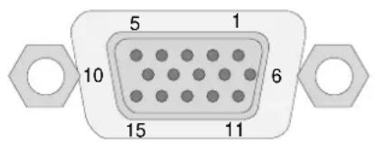
Figure 4-1. D-SUB 15 pole female connector (DE15F)
| Pin nr. | Name | Description |
| 1 | RED | Red Video (75 ohm, 0.7 V p-p) |
| 2 | GREEN | Green Video (75 ohm, 0.7 V p-p) |
| 3 | BLUE | Blue Video (75 ohm, 0.7 V p-p) |
| 4 | ID2 | Monitor ID Bit (Not used, internally connected to Pin 5) |
| 5 | GND | Ground |
| 6 | RGND | Red Ground (Internally connected to Pin 5) |
| 7 | GGND | Green Ground (Internally connected to Pin 5) |
| 8 | BGND | Blue Ground (Internally connected to Pin 5) |
| 9 | KEY | Optional +5V output from graphics card |
| 10 | SGND | Sync Ground (Internally connected to Pin 5) |
| 11 | ID0 | Monitor ID Bit 0 (Not used, internally connected to Pin 5) |
| 12 | SDA | I^2C bidirectional data line |
| 13 | HSYNC | Horizontal Sync |
| 14 | VSYNC | Vertical Sync which works also as data clock |
| 15 | SCL | I^2C data clock in DDC2 |
Table 4-2. D-sub connector pin assignment for standard VGA
4.3. Digital audio input connector
UMX-TP-TX100R has standard RCA receptacles for digital coaxial audio input.
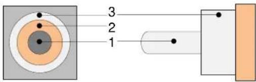
RCA receptacle RCA plug
| No | Name |
| 1 | S/PDIF input or output |
| 2 | Plastic insulator |
| 3 | GND |
Table 4-3. RCA connector pin assignments for digital audio
Info: Plugs and sockets on consumer equipment are conventionally color-coded by CEA/CEDIA-863-B (ANSI) to aid correct connections. According to the standard Lightware uses orange colored RCA connectors for S/PDIF signals.
4.4. Analog stereo audio input connectors
UMX-TP-TX100R has standard RCA receptacle for analog stereo audio input. Input works with standard line-in voltage levels.
RCA plug (left channel) RCA receptacles RCA plug (right channel)
| No | Name |
| 1 | Right channel input or output |
| 2 | Plastic insulator |
| 3 | GND |
| 4 | Left channel input or output |
| 5 | Plastic insulator |
| 6 | GND |
Table 4-4. RCA connector pin assignments for analog audio
Info: Plugs and sockets on consumer equipment are conventionally color-coded by CEA/CEDIA-863-B (ANSI) to aid correct connections. According to the standard Lightware uses red colored RCA connectors for right channel of analog stereo audio signals and white colored RCA connectors for left channel of analog stereo audio signals.
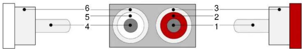
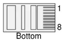
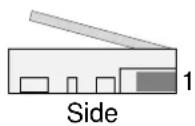
4.5. Twisted Pair outputs
UMX-TP-TX100R provides standard RJ-45 connectors for VIDEO OUT and DDC OUT. VIDEO DDC
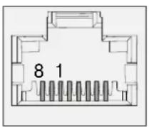
RJ45 receptacle RJ45 receptacle
| Pin | VIDEO OUT | DDC OUT |
| 1 | TMDS Data0+ | CEC (out) |
| 2 | TMDS Data0- | Hot Plug Detect (out) |
| 3 | TMDS Clock+ | RS-232 RX |
| 4 | TMDS Data1+ | DDC CLK |
| 5 | TMDS Data1- | +12V (out) |
| 6 | TMDS Clock- | RS-232 TX |
| 7 | TMDS Data2+ | DDC SDA |
| 8 | TMDS Data2- | GND |
Table 4-5. RJ45 input and output connector pin assignment
Warning: Avoid interchanging the connection to the VIDEO and DDC lines!
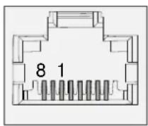
Wiring of RJ45 plugs
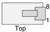
Lightware recommends the termination of TP cables on the basis of TIA/EIA T 568 A or TIA/EIA T 568 B standards.
| Pin | Name | TIA/EIA T568 A | color and name | TIA/EIA T568 B | color and name |
| 1 | TX + |  | white/green stripe |  | white/orange stripe |
| 2 | TX - |  | green solid |  | orange solid |
| 3 | RX + |  | white/orange stripe |  | white/green stripe |
| 4 | Not used |  | blue solid |  | blue solid |
| 5 | Not used |  | white/blue stripe |  | white/blue stripe |
| 6 | RX - |  | orange solid |  | green solid |
| 7 | Not used |  | white/brown stripe |  | white/brown stripe |
| 8 | Not used |  | brown solid |  | brown solid |
Table 4-6. Recommended termination of TP cables
4.6. RS-232 port
UMX-TP-TX100R has RS-232 pass-through function or can be remote controlled through industry standard 9 pole D-SUB female connector. The extender uses RS-232 port.

Figure 4-2. D-SUB 9 pole female connector (DE9F)
| Pin nr. | RS-232 |
| 1 | NC - non connected |
| 2 | TX data transmit (output) |
| 3 | RX data receive (input) |
| 4 | DTR (Internally connected to Pin 6) |
| 5 | GND signal ground (shield) |
| 6 | DSR (Internally connected to Pin 4) |
| 7 | RTS (Internally connected to Pin 8) |
| 8 | CTS (Internally connected to Pin 7) |
| 9 | NC - non connected |
Table 4-7. D-sub connector pin assignment for standard RS-232
5. Installation
5.1. Mounting of UMX-TP-TX100R
To mount extender unit Lightware supplies optional accessories for different usage. All kind of mounting kits have a similar fixing method. UMX-TX-TX100R extender unit has two mounting holes with inner thread on the bottom side. Fasten the device by screwing the enclosed M3x6 mm cross recessed, countersunk head screws (DIN 965A) through two holes of the shelf into the TP's mounting hole.
To order mounting accessories please contact sales@lightware.com.
5.1.1. Rack shelf
Allows rack mounting for half-rack, quarter-rack and pocket sized units.
1U high rack shelf provides mounting holes for fastening two half-rack or four quarter-rack sized units. Pocket sized devices can also be fastened on the self.

natural_image
Line drawing of a rectangular metal tray with two side supports and four evenly spaced holes (no text or symbols)5.1.2. Under desk mounting kit double
The UD-kit double makes it easy to mount a single device on any flat surface (e.g. furniture).
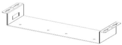
natural_image
Isometric line drawing of a rectangular metal bracket with two side panels and a central slot (no text or symbols)5.2. Maximum twisted pair distances
The following table shows the maximum twisted pair distances. The actual achievable distances may differ, depending on the topology of the whole system. Unshielded Twisted Pair (UTP) cables are susceptible to EMI coming from surrounding devices (cables, mobile phones, motors, etc.). Noisy environments substantially decrease the usable length of unshielded cables. Hence the use of shielded Category 6 cables or Category 7 cables is always recommended. Category 7 cables are screened and foiled by standard.
| Resolution | Vfreq (Hz) | Pixel clk freq. (MHz) | Cat5e UTP | Cat5e FTP | Cat6 UTP | Cat6 FTP | Cat6 S/FTP | Cat7 S/FTP |
| 640 x 480 | 60 | 25,2 | 60 m | 60 m | 65 m | 70 m | 70 m | 80 m |
| 800 x 600 | 60 | 40,0 | 60 m | 60 m | 65 m | 65 m | 65 m | 75 m |
| 1024 x 768 | 60 | 65,0 | 55 m | 55 m | 60 m | 60 m | 60 m | 75 m |
| 1280 x 720p | 60 | 74,2 | 55 m | 55 m | 60 m | 60 m | 60 m | 70 m |
| 1280 x 1024 | 60 | 108,0 | 50 m | 50 m | 55 m | 60 m | 60 m | 65 m |
| 1400 x 1050 | 60 | 121,8 | 45 m | 45 m | 45 m | 55 m | 55 m | 60 m |
| 1600 x 1200 | 60 | 162,0 | 30 m | 35 m | 35 m | 45 m | 45 m | 50 m |
| 1920 x 1080p | 60 | 148,5 | 30 m | 35 m | 35 m | 45 m | 45 m | 50 m |
| 1920 x 1200p | 60 | 153,0 | 30 m | 35 m | 35 m | 45 m | 45 m | 50 m |
Table 5-1. Maximum twisted pair distances
5.3. About serial devices
5.3.1. General information about serial communication
In our aspect there are two types of devices in general serial communication:
- Data Terminal Equipment – Data Terminal Equipment (DTE) is an end instrument that converts user information into signals or reconverts received signals. Typical DTE devices: computers, LCD touch panels and control systems.
- Data Circuit-terminating Equipment – Data Circuit-terminating Equipment (DCE) is a device that sits between the DTE and a data transmission circuit. It also called data communication equipment and data carrier equipment. Typical DCE devices: projectors, industrial monitors and amplifiers.
Among others the pin assignment is different between DTE and DCE.
| DTE | DCE | |
| Pin 2: | RD | TD |
| Pin 3: | TD | RD |
RD: Received Data (digital input)
TD: Transmitted Data (digital output)
Info: UMX-TP-TX100R is DCE units according to their pin-out.
Different type of serial cables must be used between different serial devices.
| DTE | DCE | |
| DTE | Null-modem | Straight |
| DCE | Straight | Null-modem* |
* in general contact DCE with DCE by tail-circuit serial cable. To connect UMX-TP-TX100R and a DCE unit use male-male null-modem cable.
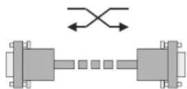
5.3.2. Type of serial cables
- Straight serial cable – straight pin-outs both ends
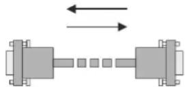
- Null-modem serial cable – straight pin-out at the one end and cross pin-out at the other end. (Interchange lines of TX and RX).
5.3.3. Example connection diagrams
The following cases are examples. Devices may have different receptacles and pin-outs.
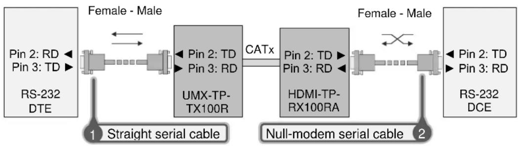
- To extend RS-232 between controller system (DTE) and projector (DCE).
Connect straight serial cable between controller system (DTE) and the UMX-TP-TX100R transmitter (DCE) and null-modem serial cable between HDMI-TP-TX100RA receiver (DCE) and projector (DCE).
flowchart
graph LR
    A["RS-232 DTE"] --> B["Female - Male"]
    B --> C["1 Straight serial cable"]
    C --> D["Pin 2: TD\nPin 3: RD\nUMX-TP-TX100R"]
    D --> E["Catx"]
    E --> F["HDMI-TP-RX100RA"]
    F --> G["2 Null-modem serial cable"]
    G --> H["RS-232 DCE"]
    I["Pin 2: TD\nPin 3: RD"] --> J["Female - Male"]
    J --> K["1 Straight serial cable"]
    K --> L["Pin 2: TD\nPin 3: RD\nUMX-TP-TX100R"]
    L --> M["Catx"]
    M --> N["HDMI-TP-RX100RA"]
    N --> O["2 Null-modem serial cable"]
    O --> P["RS-232 DCE"]
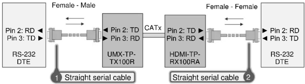
- To extend RS-232 between computer (DTE) and computer (DTE).
Connect straight serial cable between controller system (DTE) and the UMX-TP-TX100R transmitter (DCE) and straight serial cable between HDMI-TP-TX100RA receiver (DCE) and computer (DTE).
flowchart
graph LR
    A["RS-232 DTE"] --> B["Pin 2: RD"]
    A --> C["Pin 3: TD"]
    B <--> D["1 Straight serial cable"]
    C <--> E["2 Straight serial cable"]
    F["RS-232 DTE"] --> G["Pin 2: RD"]
    F --> H["Pin 3: TD"]
    I["FMX-TP-TX100R"] --> J["Pin 2: TD"]
    I --> K["Pin 3: RD"]
    L["HDMI-TP-RX100RA"] --> M["Pin 2: TD"]
    L --> N["Pin 3: RD"]
    O["Female - Male"] --> P["1 Straight serial cable"]
    Q["Female - Female"] --> R["2 Straight serial cable"]
    style A fill:#f9f,stroke:#333
    style F fill:#ccf,stroke:#333
    style Q fill:#ccf,stroke:#333
5.4. Connecting serial devices
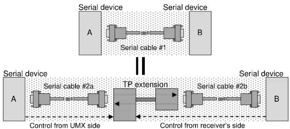
Serial cables between devices may have male or female plugs and their type may be straight or null-modem.
Info The cable type does not depend on the plug type.
Use of the RS-232 pass-through or the control mode places extender units* between serial devices in the topology. TP extension functions as an extra-long straight serial cable. So out of the Serial cables #2a and #2b, one must be the same type (e.g. straight or null-modem) as Serial cable #1 and the other one must be a straight serial cable. If cable's plug and device's receptacle do not match get a suitable cable or use a gender changer.
* Extender units can be UMX-TP-TX100R and any Lightware TP receiver or Lightware Hybrid Matrix equipped with double slot twisted pair input cards, etc. For the compatible Lightware products please see the compatibility table at www.lightware.com.
flowchart
graph LR
    subgraph_Serial_device_1["Serial device"]
        A1["A"] --> A2["B"]
        A2 --> A3["Serial cable #1"]
    end
    subgraph_Serial_device_2["Serial device"]
        A4["A"] --> A5["B"]
        A5 --> A6["Serial cable #2a"]
        A6 --> A7["TP extension"]
        A7 --> A8["Serial cable #2b"]
        A8 --> A9["Control from receiver's side"]
    end
    A1 -.-> A4
    A2 -.-> A5
    A3 -.-> A7
    A4 -.-> A8
    A5 -.-> A9
    A6 -.-> A7
    A7 -.-> A8
    A8 -.-> A9
    A9 -.-> B
Figure 5-1. Connecting serial devices
5.5. Operation modes
There are two kinds of operations for the unit regarding the serial port: you can control the unit or use the bidirectional serial link through the DDC CAT cable with a compatible HDMI-TP receiver.
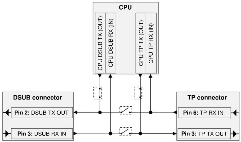
5.5.1. Control mode
In the first case the CPU in the transmitter can receive commands and send responses either to and from the own serial port or to and from the serial port on the receiver unit through the DDC line (2nd CAT cable).
flowchart
graph TD
    CPU["CPU"] -->|CPU DSUB TX (OUT)| DSUB["DSSUB CONNECTOR"]
    CPU -->|CPU DSUB RX (IN)| DSUB
    CPU -->|CPU TP TX (OUT)| TPDC["TP CONNECTOR"]
    CPU -->|CPU TP RX (IN)| TPDC
    DSUB -->|Pin 2: DSUB TX OUT| DSUB
    DSUB -->|Pin 3: DSUB RX IN| DSUB
    TPDC -->|Pin 6: TP RX IN| TPDC
    TPDC -->|Pin 3: TP TX OUT| TPDC
    DSUB -->|Pin 2: DSUB TX OUT| DSUB
    DSUB -->|Pin 3: DSUB RX IN| DSUB
Figure 5-2. UMX-TP-TX100R in control mode
5.5.2. Pass-through mode
In case of the second mode the TX lines of the processor are in HiZ state and the serial connectors on the transmitter and on the receiver are linked together through the DDC CAT cable.

flowchart
graph TD
    A["CPU"] --> B["CPU DSUB TX (OUT)"]
    A --> C["CPU DSUB RX (IN)"]
    A --> D["CPU TP TX (OUT)"]
    A --> E["CPU TP RX (IN)"]
    B --> F["DSUB connector"]
    C --> F
    D --> F
    E --> F
    F --> G["Pin 2: DSUB TX OUT"]
    F --> H["Pin 3: DSUB RX IN"]
    I["TP connector"] --> J["Pin 6: TP RX IN"]
    I --> K["Pin 3: TP TX OUT"]
    style A fill:#f9f,stroke:#333
    style I fill:#ccf,stroke:#333
Figure 5-3. UMX-TP-TX100R in pass-through mode
5.5.3. Changing the working mode
Turn both of the rotary switches to address #2, and press and hold the LEARN button for approximately 3 seconds.
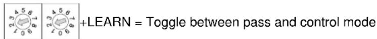
The status change appears on the LED tower. If the working mode becomes pass-through the LEDs flash from top to bottom sequentially. If the working mode becomes control the LEDs flash from bottom to top sequentially.
Changing the working mode can be done by protocol command (section 8.4.5 on page 57) or the Lightware Matrix Controller software (section 7.3.2 on page 41).
Info: UMX-TP-TX100R stores the RS-232 working mode and starts the saved one after reboot.
The default baud rate for control is 57600, the command to set the baud rate can be the following: 9600, 19200, 38400, 57600 and 115200.
Of course in PASS mode the speed can be anything, but for changing and querying the mode the previously set baud rate must be applied for the sent commands.
For more information see section 8.4.2 on page 56.
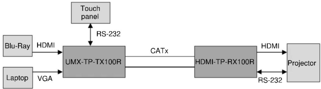
5.5.4. Detailed example:
flowchart
graph LR
    A["Blu-Ray"] -->|HDMI| B["UMX-TP-TX100R"]
    C["Laptop"] -->|VGA| B
    B -->|CATx| D["HDMI-TP-RX100R"]
    D -->|HDMI| E["Projector"]
    F["Touch panel"] <-->|RS-232| B
    D <-->|RS-232| E
Figure 5-4. Example system diagram
The system consists of the following: a Blu-Ray player and a laptop as sources, a programmable touch panel as a controller, then a Lightware UMX-TP-TX100R and HDMI-TP-RX100R as the TP extenders, then a projector as a sink device. The touch panel has three buttons. The desired functions of the buttons are that they can power on and off the projector, and switch between the inputs. Let's examine the detailed solution.
Three types of the touch panel's commands:
( ): settings of the touch panel / not sent /
[ ]: command to the projector / sent via RS-232 /
{}: command to the UMX-TP-TX100R / sent via RS-232 /
Initializing:
First of all the touch panel can control the projector only if RS-232 settings are the same for the touch panel and the projector.
Commands: Comments:
(set_RS-232) /* Set the appropriate RS-232 settings which are fit to the UMX-TP-TX100R and the projector as well. */
Button 1 (Power on the projector):
The touch panel can control the projector only if the UMX-TP-TX100R is in pass-through mode.
{RS232=PASS} /* Set the UMX-TP-TX100R in pass-through mode */ [projector_on] /* Power on the projector */
Button 2 (Select the HDMI input):
The touch panel can only control the UMX-TP-TX100R if that is in control mode.
Commands: Comments:
{RS232=CONTROL} /* Set the UMX-TP-TX100R in control mode */ {1@1 AV} /* Select the HDMI input on the UMX-TP-TX100R */
Button 3 (Power off the projector):
The touch panel can control the projector only if the UMX-TP-TX100R is in pass-through mode.
Commands: Comments:
{RS232=PASS} /* Set the UMX-TP-TX100R in pass-through mode */ [projector_off] /* Power off the projector */
5.6. Powering device
Warning! When building an electronic system, make sure that all of the devices are powered down before connecting them. Powered on devices may have dangerous voltage levels that can damage sensitive electronic circuits.
UMX-TP-TX100R doesn't have any jumper, because the power supply is automatic. User must handle the receiver's power settings only. Please read out carefully the receiver unit user's manual for the appropriate jumper settings.
Figure 5-5. shows the most frequently power settings of the receivers with the UMX-TP-TX100R transmitter.
Warning! Please check the receivers' power settings before they are switched on.
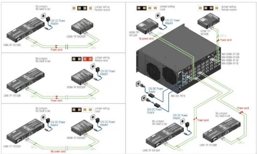
Figure 5-5. Power settings
5.6.1. Boot up of HDMI-TP extender units
After all the other connections in the system are complete, connect the output of the +12V Power Adaptor to the UMX-TP-TX100R.
The special locking DC plug provides safe connection. Plug the connector into the +12V 1A DC IN receptacle and twist 90^ clockwise to lock it. Plug the adaptor into the electric outlet. The unit is immediately powered ON.

Figure 5-6. Locking DC plug
After being powered on, the UMX-TP-TX100R lights up all LEDs, than displays its firmware version using the three upper front panel LEDs. The top LED means the first number of the firmware version, actually this is the main version. From the top the second and the third LEDs mean the second and the third number of the firmware version, actually these are the subversions.
The following example shows this process for a firmware version of 1.0.9
The top LED blinks once → Short pause → The second LED does not blink, this means the number 0 → Short pause → The third LED blinks nine times → Short pause → The normal function of the LED is in effect.
After indicating the firmware version, UMX-TP-TX100R checks the video output: reads the EDID if there is a Hot Plug signal and authenticates devices in case of HDCP encryption. This procedure takes approximately 5 seconds.
UMX-TP-TX100R stores the video and audio crosspoint state in a non-volatile memory and after booting it starts with it.
After the UMX-TP-TX100R is initialized, the attached source(s), receiver pair and monitor(s) can be powered on.
Info
If none of the LEDs light up upon power-up, the unit is most likely damaged and further use is not advised. Please contact support@lightware.com
6. Operation of UMX-TP-TX100R
6.1. Front panel LEDs
To save space and simplify readability UMX-TP-TX100R uses only four LEDs to inform the users about the connections, crosspoint state, the video signals and so on. Because of the low numbers of LEDs several functions are used to display information.
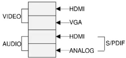
Figure 6-1. Legend of the LED bar
Firmware indication
After being powered on, the UMX-TP-TX100R lights up all LEDs, than displays its firmware version using the three upper front panel LEDs.
After being powered on, the UMX-TP-TX100R lights up all LEDs, than displays its firmware version using the three upper front panel LEDs. The top LED means the first number of the firmware version, actually this is the main version. From the top the second and the third LEDs mean the second and the third number of the firmware version, actually these are the subversions.
The following example shows this process for a firmware version of 1.0.9
The top LED blinks once → Short pause → The second LED does not blink, this means the number 0 → Short pause → The third LED blinks nine times → Short pause → The normal function of the LED is in effect.
Signal state in DIRECT SELECT mode
VIDEO
If there is a valid incoming video signal on the selected video input port (e.g. HDMI) the corresponding LED (HDMI VIDEO) lights continuously. If the video input port is selected but there is no valid incoming video signal, the corresponding video LED blinks continuously.
AUDIO
If the HDMI or VGA audio input port is selected the HDMI or ANALOG AUDIO LED lights continuously. If the S/PDIF audio input port is selected both of the AUDIO LEDs (the HDMI and the ANALOG AUDIO LED together) lights continuously.
Signal state in AUTOSELECT mode
VIDEO
If there is no incoming video signal on either of the video input ports the device searches active video sources. During this process the HDMI VIDEO and the VGA VIDEO LEDs blink alternately and AUDIO LEDs are off. If an active video signal was found and selected the corresponding VIDEO LED lights up.
AUDIO
During the searching process the AUDIO LEDs are off. If the HDMI or VGA audio input port is selected the HDMI or ANALOG AUDIO LED lights continuously. If the S/PDIF audio input port is selected both of the AUDIO LEDs (the HDMI and the ANALOG AUDIO LED together) lights continuously.
EDID management
Successful EDID learning
All the four LEDs blink 3 times in 3 seconds. (slow blinking)
Unsuccessful EDID learning
All the four LEDs blink 15 times in 2 seconds. (fast blinking)
Entering autoselect mode
The HDMI and VGA LEDs blinks alternately for 3 seconds while audio LEDs are off.
6.2. Input selection
Video and Audio input can be chosen with:
VIDEO and AUDIO SELECT button on the front panel
AUTOSELECT mode
Lightware Matrix Controller software (section 7.3.1 on page 41)
Protocol command (section 8.6.1 on page 64)
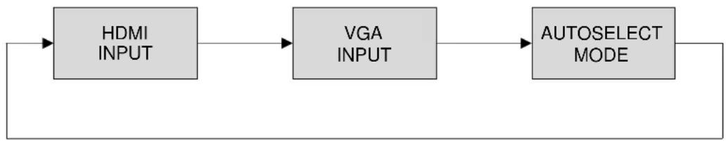
6.2.1. VIDEO INPUT selection
The order of the video selection is shown on the Figure 6-2. After the VIDEO SELECT button was pushed, the next input will be chosen. The corresponding LED lights up.
flowchart
graph LR
    A["HDMI INPUT"] --> B["VGA INPUT"]
    B --> C["AUTOSELECT MODE"]
    C --> D["Output"]
Figure 6-2. Video input selection order
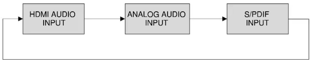
6.2.2. AUDIO INPUT selection
The order of the audio selection is shown on the Figure 6-3. After the AUDIO SELECT button was pushed, the next input will be chosen. The corresponding LED lights up.
flowchart
graph LR
    A["HDMI AUDIO INPUT"] --> B["ANALOG AUDIO INPUT"]
    B --> C["S/PDIF INPUT"]
    C --> D["Output"]
Figure 6-3. Audio input selection order
6.2.3. AUTOSELECT mode
The Autoselect function means UMX-TP-TX100R can recognize the incoming valid video signals on both input ports and can choose one automatically, without user intervention.
The AUTOSELECT mode can work in two ways:
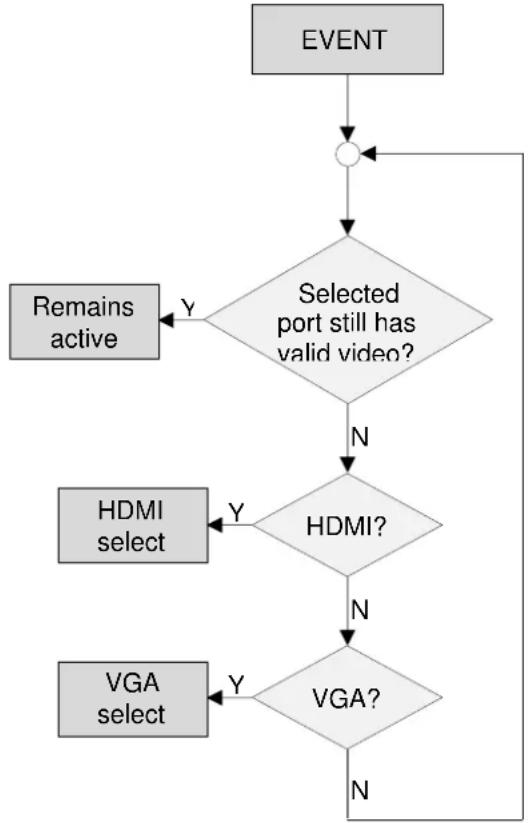
- Non-priority (first detect): The device checks the HDMI input first. If there is a valid video signal on the HDMI input it will be selected. If there is no video signal on the HDMI input the device checks the VGA input. If there is a valid video signal on the VGA input it will be selected. If there is no video signal on the VGA input neither the searching process starts again.
If the selected input was unplugged or the valid video signal was disappeared the searching process starts again.
If one input port (e.g. VGA) was selected - and there is a valid video signal on it - and a valid video signal was appeared on the other input port (HDMI) - by connecting or powering on a video source - the searching process does NOT start again. The previous selected video input port (VGA) remains the active one.
flowchart
graph TD
    A["EVENT"] --> B{Selected port still has valid video?}
    B -->|Y| C["Remains active"]
    B -->|N| D{HDMI?}
    D -->|Y| E["HDMI select"]
    D -->|N| F{VGA?}
    F -->|Y| G["VGA select"]
    F -->|N| H["End"]
Figure 6-4. Non-priority video selection flowchart
- Priority: The device checks the HDMI input first. If there is a valid video signal on the HDMI input it will be selected. If there is no video signal on the HDMI input the device checks the VGA input. If there is a valid video signal on the VGA input it will be selected. If there is no video signal on the VGA input neither the searching process starts again.
If the selected input was unplugged or the valid video signal was disappeared the searching process starts again.
If one input port (e.g. VGA) was selected - and there is a valid video signal on it - and a valid video signal was appeared on the other input port (HDMI) - by connecting or powering on a video source - the searching process STARTS AGAIN with checking the HDMI input. The previous selected video input port (VGA) becomes inactive and the privileged one (HDMI) becomes active.
In brief in case of incoming valid HDMI video signal on the HDMI input, it will always be selected even if there was an earlier selected VGA video signal.
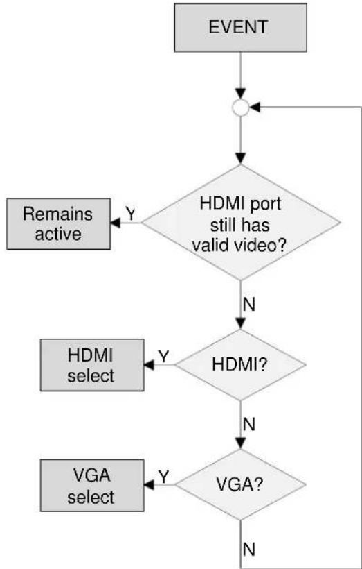
flowchart
graph TD
    A["EVENT"] --> B{HDMI port still has valid video?}
    B -->|Y| C["Remains active"]
    B -->|N| D{HDMI?}
    D -->|Y| E["HDMI select"]
    D -->|N| F{VGA?}
    F -->|Y| G["VGA select"]
    F -->|N| H["End"]
Figure 6-5. Priority video selection flowchart
User can toggle between the two AUTOSELECT priority modes with protocol command. For more information see chapter 8.4.13 on page 59.
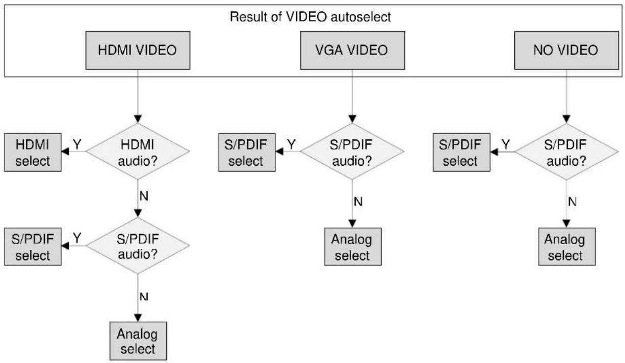
6.2.4. Audio input in AUTOSELECT mode
The AUDIO input selection is linked to the VIDEO input selection in the AUTOSELECT mode:
If there is no video signal neither HDMI nor VGA input the device checks the S/PDIF audio input. If there is valid S/PDIF audio signal on the S/PDIF input port this port will be selected. If there is no S/PDIF audio the device checks the analog audio input. If there is valid analog audio signal on the analog input port this port will be selected. If there is no analog audio the searching process starts again.
If there is a valid incoming HDMI video signal on the HDMI input port the device checks the HDMI embedded audio input. If there is valid embedded HDMI audio signal on the HDMI input port this port will be selected. If there is no embedded HDMI audio the device checks the S/PDIF audio input. If there is valid S/PDIF audio signal on the S/PDIF input port this port will be selected. If there is no S/PDIF audio the device the analog audio input will be selected.
If there is a valid incoming VGA video signal on the VGA input port the device checks the S/PDIF audio input. If there is valid S/PDIF audio signal on the S/PDIF input port this port will be selected. If there is no S/PDIF audio the device the analog audio input will be selected.
To better understand the audio input selection in autoselect mode please study the below diagram.
flowchart
graph TD
    A["HDMI VIDEO"] --> B{HDMI audio?}
    B -->|Y| C["HDMI select"]
    B -->|N| D{S/PDIF audio?}
    D -->|Y| E["S/PDIF select"]
    D -->|N| F["Analog select"]
    G["VGA VIDEO"] --> H{S/PDIF audio?}
    H -->|Y| I["S/PDIF select"]
    H -->|N| J["Analog select"]
    K["NO VIDEO"] --> L{S/PDIF audio?}
    L -->|Y| M["S/PDIF select"]
    L -->|N| N["Analog select"]
    B --> O["HDMI select"]
    D --> P["S/PDIF select"]
    O --> Q["Analog select"]
    P --> R["HDMI select"]
    Q --> S["Analog select"]
Figure 6-6. Audio input selection order in AUTOSELECT mode
6.3. About EDID memory
EDID memory is non-volatile and consists of four blocks, each for different purpose. These blocks are:
• Factory preset EDIDs
- User saved EDIDs
• Dynamic EDID (EDID of last connected sink on the DDC output port)
- Emulated EDIDs (EDID currently emulated on a specific input port)
This manual refers to the EDIDs in two ways:
6.3.1. EDIDs are referred with Lightware Matrix Controller
In the first case EDID is mentioned with the Matrix Controller software or the protocol commands. EDIDs are numbered from 1 in each block, and they can be referred as the first letter of the block name, and the number of the desired EDID. This way F02 refers to the second factory preset EDID, and D01 refers to the display device's EDID on the output (on the receiver's output).
The EDID memory structure in protocol reference:
Factory Preset EDIDs (F01 .. F10):
F01 .. F05 ...... HDMI Factory Preset EDIDs F06 .. F10 ...... VGA Factory Preset EDIDs
User programmable memories (U01 .. U08):
U01 .. U04 ....User programmable HDMI memories U05 .. U08 ....User programmable VGA memories
Last attached monitor's EDID: (D01):
D01 ....Last attached monitor's EDID on the output E01 ....Emulated EDID on the HDMI input
Emulated EDIDs (E01 .. E02):
E01 .. E02 ......Emulated EDIDs on the VGA input
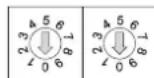
6.3.2. EDIDs are referred with rotary switches
In the second case EDID is mentioned with the rear panel rotary switches. EDIDs are numbered from 0 on each rotary, and they can be referred with hash symbol, and the number of the desired EDID. This way #6 refers to the first user preset EDID, and #0 refers to the display device's EDID on the output (on the receiver's output).
The EDIDs can be chosen by rotary switches:
| HDMI EDID rotary | VGA EDID rotary | ||
| #0 | Copy from TP OUT (Dynamic EDID) | #0 | Copy from TP OUT (Dynamic EDID) |
| #1 | FACTORY EDID Universal HDMI (default) | #1 | FACTORY EDID Universal VGA (default) |
| #2 | FACTORY EDID (DVI) 1024x768@60 | #2 | FACTORY EDID 1024x768@60 |
| #3 | FACTORY EDID (HDMI) 1280x720p@60 | #3 | FACTORY EDID 1280x720@60 |
| #4 | FACTORY EDID (HDMI) 1920x1080p@60 | #4 | FACTORY EDID 1920x1080@60 |
| #5 | FACTORY EDID (DVI) 1920x1200@60 | #5 | FACTORY EDID 1920x1200@60 |
| #6 | USER EDID 1 (def.: Univ. HDMI EDID) | #6 | USER EDID 1 (def.: Univ. VGA EDID) |
| #7 | USER EDID 2 (def.: Univ. HDMI EDID) | #7 | USER EDID 2 (def.: Univ. VGA EDID) |
| #8 | USER EDID 3 (def.: Univ. HDMI EDID) | #8 | USER EDID 3 (def.: Univ. VGA EDID) |
| #9 | USER EDID 4 (def.: Univ. HDMI EDID) | #9 | USER EDID 4 (def.: Univ. VGA EDID) |
6.3.3. The assigning table
To help understand the EDID memory structure see the matching table below. It shows all the EDIDs, their short descriptions and their references.
| Number on HDMI EDID rotary | EDIDs for HDMI Input | EDID reference in protocol |
| #0 | Copy from TP OUT (Dynamic EDID) | D0 |
| #1 | Factory EDID Universal HDMI (default) | F1 |
| #2 | Factory EDID (DVI) 1024x768@60 | F2 |
| #3 | Factory EDID (HDMI) 1280x720p@60 | F3 |
| #4 | Factory EDID (HDMI) 1920x1080p@60 | F4 |
| #5 | Factory EDID (DVI) 1920x1200@60 | F5 |
| #6 | User EDID (def.: Univ. HDMI EDID) | U1 |
| #7 | User EDID (def.: Univ. HDMI EDID) | U2 |
| #8 | User EDID (def.: Univ. HDMI EDID) | U3 |
| #9 | User EDID (def.: Univ. HDMI EDID) | U4 |
| Number on VGA EDID rotary | EDIDs for VGA Input | EDID reference in protocol |
| #0 | Copy from TP OUT (Dynamic EDID) | D0 |
| #1 | Factory EDID Universal VGA (default) | F6 |
| #2 | Factory EDID 1024x768@60 | F7 |
| #3 | Factory EDID 1280x720@60 | F8 |
| #4 | Factory EDID 1920x1080@60 | F9 |
| #5 | Factory EDID 1920x1200@60 | F10 |
| #6 | User EDID (def.: Univ. VGA EDID) | U5 |
| #7 | User EDID (def.: Univ. VGA EDID) | U6 |
| #8 | User EDID (def.: Univ. VGA EDID) | U7 |
| #9 | User EDID (def.: Univ. VGA EDID) | U8 |
All EDIDs (including factory presets; user programmable memories and EDID at TP output) can be switched and emulated at any of the inputs.
Info: The factory EDIDs (Fxx) are factory preprogrammed and cannot be modified. These are the most commonly used resolutions.
Info: UMXTP-TX100R can handle both 128 Byte EDID and 256 Byte extended EDID structures.
Info: The attached monitor's EDID is stored automatically, until a new monitor is attached to that particular output. In case of powering the unit off, the last attached monitor's EDID remains in non-volatile memory even is the monitor is unconnected.
Warning! Emulated EDIDs can be switched with the rotary switches only.
6.4. EDID types
Most of the factory preset EDIDs include only one resolution. This is to force the connected source to give a signal with the needed resolution. However there are Universal EDIDs as well which allow many resolutions.
The factory EDIDs are divided into groups regarding their type. Some EDIDs are supporting DVI only, some support HDMI, and some are for analog VGA signals.
Analog EDIDs can be used for VGA (RGBH) input port.
DVI EDIDs does not support embedded audio.
HDMI EDIDs support embedded audio. These EDIDs – include Universal HDMI EDID - indicate that any audio format is accepted (PCM, Dolby, DTS, etc.).
Info: Analog and HDMI user EDIDs are the Universal Analog and HDMI EDIDs in factory defaults.
6.4.1. Factory preset EDID list
Lightware factory pre-loaded EDIDs are specially provided to force graphic cards to output only the exact pixel resolution and refresh rate.
HDMI and VGA universal EDIDs (#1 on both rotary switches) allow multiple resolutions including all common VESA defined resolutions. In addition, HDMI universal EDID also features audio support. The use of universal EDID is recommended for fast and easy system setup.
| Mem. | Resolution | Type | Audio support | Deep color support | |||
| PCM | Other | 24 bit | 30 bit | 36 bit | |||
| F01 | Universal_HDMI_DC | HDMI | √ | √ | √ | x | √ |
| F02 | 1024 x 768 @ 60.0 Hz | DVI | x | x | x | x | x |
| F03 | 1280 x 720 @ 60.0 Hz | HDMI | √ | x | √ | x | x |
| F04 | 1920 x 1080 @ 60.0 Hz | HDMI | √ | x | √ | x | x |
| F05 | 1920 x 1200 @ 59.55 Hz | DVI | x | x | x | x | x |
| F06 | Universal_Analog | Analog | x | x | x | x | x |
| F07 | 1024 x 768 @ 60.0 Hz | Analog | x | x | x | x | x |
| F08 | 1280 x 720 @ 60.0 Hz | Analog | x | x | x | x | x |
| F09 | 1920 x 1080 @ 60.0 Hz | Analog | x | x | x | x | x |
| F10 | 1920 x 1200 @ 59.55 Hz | Analog | x | x | x | x | x |
Table 6-1. Factory Preset EDID list
Info The first 10 EDID (#1..#10 inclusive) are factory preprogrammed and cannot be modified. These are the most commonly used resolutions.
6.5. Learning the EDID
The factory preset EDIDs cannot be changed by the user. Only addresses #6 .. #9 (on both rotary switches) are user programmable.
Important! EDID learning is only available from the active input to a user memory location which was selected by a rotary switch. EDID learning is not allowed in AUTOSELECT mode.
Info: Before a digital EDID will be saved into a VGA memory location UMX-TP-TX100R removes the digital descriptor from the EDID, and saves it.
After connecting the sink device to the unit's output (for example the receiver unit's HDMI OUT), use a screwdriver to select an empty memory address. EDIDs are stored in a multiple programmable non-volatile memory.
Push the LEARN button on the front side of the device and hold it down for approximately 3 seconds.
If the EDID storing was successful, all the status LEDs blink 3 times in 3 seconds slowly then they return to their original function.
If the storing was unsuccessful, all the status LEDs blink 15 times in 2 seconds quickly then they return to their original function.
Info: The last attached monitor's EDIDs are stored automatically, until a new monitor is attached to the output (or receiver's output). In case of powering the unit off, the last attached monitor's EDID remains in non-volatile memory.
Info: As a matter of fact UMX-TP-TX100R always learns the stored last attached monitor's EDID into the user programmable EDID memory. If the attached sink device on the output is unplugged pushing and holding the LEARN EDID button causes a successful EDID learning without plugging in the monitor again. (even after a power reset)
6.6. Switching the EDID
Use a screwdriver to change the memory address on the rear side of the UMX-TP-TX100R.
After either one of the rotary switches has been rotated, the unit waits approximately 2 seconds before the selected EDID becomes active.
The address #0 (on both rotary switches) has a special function. If a receiver is connected to the output, then its EDID is copied to the input connector. If no receiver is connected to the output then the EDID transmitted to the input connector is the EDID of the last connected monitor.
Info: If an invalid EDID is selected, the UMX-TP-TX100R does NOT give a HOT PLUG signal to the input (HDMI or VGA).
Info After every EDID change, UMX-TP-TX100R toggles the HOT PLUG signal for approx. 1 second. Some graphic cards or DVD players do not sense the HOT PLUG signal, and even if EDID has been changed, the set resolution is not affected. In this case the source device must be restarted, or powered OFF and ON again.
Important! Switching EDID is available only with rotary switches. (Switching with Lightware Matrix Controller Software or protocol command is not available.)
6.7. Deleting the EDID
Only user EDIDs can be deleted. Deleting means the factory EDID (Universal HDMI or Analog EDID) will be loaded into the desired user EDID memory.
6.8. Invalid EDID on any input
Invalid EDID doesn't occur under normal operation. If it does occur due to unexpected circumstances status LEDs indicate it with the following method:
If an input port (HDMI or VGA) was selected by user or autoselect where invalid EDID is, the affected port's status LED (HDMI or VGA) lights continuously and the audio LEDs (HDMI Audio and Analog Audio) blink together.
6.9. HDCP management
The UMX-TP-TX100R can work as a HDCP compliant device, or act as a non-HDCP compliant sink. The HDCP capability can be disabled or enabled on the digital video input port. This function helps to apply encryption only when it is mandatory.
Some video sources send encrypted signal when they are connected to a HDCP capable device even if the content is not protected. This way even the unprotected content cannot be displayed on non-HDCP displays if the signal travels through a HDCP compliant matrix or repeater.
However HDCP encryption is not required all the time (e.g. computer desktop image) some video cards still encrypt if they detect that the sink is HDCP capable.
Avoiding unnecessary HDCP encryption
If HDCP is disabled on the digital video input port, the connected source will detect that the sink is not HDCP capable, and turn off authentication. The source will not be able to communicate with any of the devices (displays, repeaters, etc.) that are connected to the receiver's output, therefore it could not see if they are HDCP capable or not.
This forces the source to send unprotected signal only. If HDCP capability is disabled on an input port, the connected source cannot send protected content to any display. If HDCP function is enabled on an input port and the source sends encrypted signal, the non-HDCP compliant devices cannot display the video.
Info: In HDCP disable mode, protected content (i.e. Blu-ray disc) will not be displayed, thus maintaining the rules set by the HDCP standard.

To toggle the HDCP function, use Matrix Controller software (see section 7.3.3 on page 41), use protocol command (see section 8.8.1 on page 67), or turn both of the rotary switches to address #1, and press and hold the LEARN button for approximately 3 seconds.

+LEARN = HDCP enable / disable
The status change appears on the LED tower. If HDCP is disabled the LEDs flash from top to bottom sequentially. If HDCP is enabled the LEDs flash from bottom to top sequentially.
HDCP key counter
HDCP key counter is a tool that counts and validates the number of keys that can be accepted by a source device when connected to an HDCP repeater.
HDCP key counting is available with protocol command. For more information, see section 8.4.7 on page 57.
6.10. No sync color
The device generates a solid 640x480 resolution image when there is no incoming signal. The color of this picture can be set in the Lightware Matrix Controller software (section 7.3.3 on page 41) or with protocol command (section 8.8.12 on page 73).
6.11. Hardware reset
If any malfunction is noticed and the device does not respond it can be necessary to have a hardware reset. Push and release the reset button to restart the device.
This process can be induced by protocol command as well. For more information see section 8.4.9 on page 58.
Info: Saved settings and EDIDs will be remained after the reboot.
6.12. Reload factory defaults
Factory default settings can be reloaded with the procedure below:
+LEARN = Restore factory defaults
Turn both of the rotary switches to address #0, and press and hold the LEARN button for approximately 3 seconds.
After restoring default values the device reboot automatically.
This operation affects the crosspoint table and configuration, input and output names, I/O settings and stored User and Dynamic EDIDs.
Warning! User and Dynamic EDIDs will be cleared (refilled with Lightware Universal EDID) after reloading the factory defaults.
Warning!
Reloading factory defaults by rotary switches plus learn button AFFECTS the serial operation mode and the RS-232 baud rate options as well. The default operation mode is the CONTROL mode and the default baud rate is 57600 baud in the UMX-TP-TX100R. If the previous serial settings differ from the default ones, please set up the necessary values after reboot with protocol commands. (Set the RS-232 operation mode command in section 8.4.5 on page 57 and the Change RS-232 baud rate command in section 8.4.2 on page 56)
This process can be induced by protocol command as well, but reload factory defaults by protocol command does NOT AFFECTS the serial operation mode and the baud rate options. For more information see section 8.4.4 on page 56.
7. Software control – Using the Lightware Matrix Controller
The device can be controlled using the Lightware Matrix Controller from a Windows PC or Laptop through RS-232 port.
7.1. Installing the Matrix Controller software
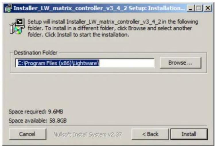
Step 1. Run Installer_LW_matrix_controller_v3_4_2.exe
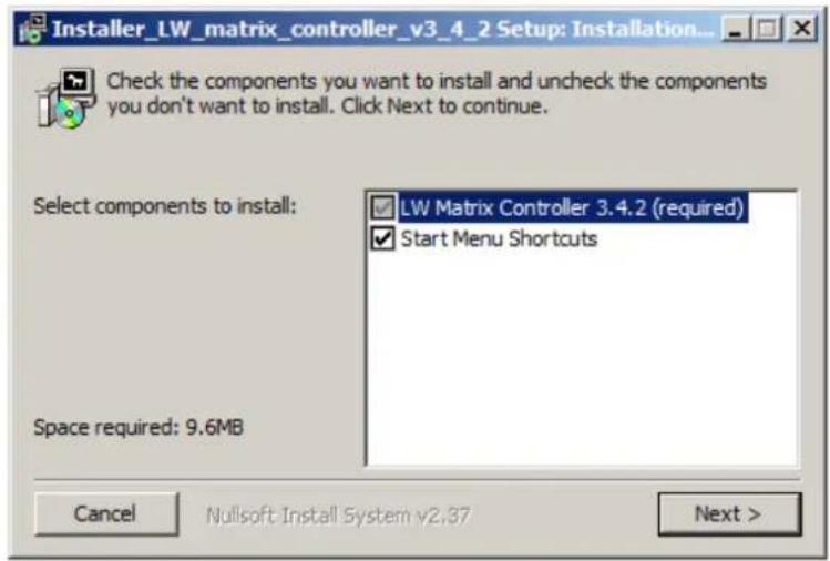
Step 2. Select destination folder and click Install (Using the default path is highly recommended)
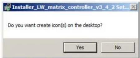
Step 3. If you want to create desktop icon click Yes in the next pop-up window:
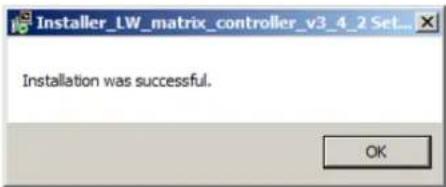
Step 4. After finishing the installation the following message appears:
Step 5. To run Lightware matrix control software find the shortcut icon in Start menu → Programs → Lightware → LW_matrix_controller_v3.4.2 or on the desktop, and double click:

LW_matrix_controller_v
3_4_2
Uninstalling
To uninstall the control software double click on: Start menu → Programs → Lightware → LW_matrix_controller_v3_4_2 → Uninstall
7.2. Establishing the connection
The unit can be controlled from a Windows computer using Lightware Matrix Controller software through RS-232 connection.
Info: Lightware Matrix Controller can works with two baud rates: 9600 Baud or 57600 Baud. The software is able to recognize and set the appropriate baud rate from the two values mentioned above, but these values cannot set or changed by the user. If the computer has different serial communication settings (e.g. 19200 Baud) the Matrix Controller software cannot connect to the device.
Step 1. Connect the device and the computer via serial port, with RS-232 Male to Female cable (straight through).

LW_matrix_controller_v
3_4_2
Step 2. Start the application
To run the CONTROL SOFTWARE double click on the icon of the software on the desktop or select proper shortcut from Start Menu → Programs → Lightware folder.
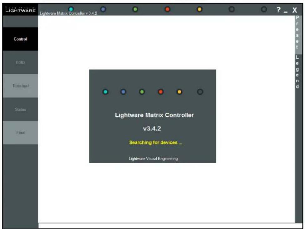
Figure 7-1. Matrix Controller software startup
Step 3. The Find dialog appears automatically
If the connection has been made via serial port, the device type and serial number can be inquired by double clicking the appropriate port, or it can be highlighted with a single click.
Info:
Lightware Matrix Controller software can only connect to the extender if it is in control mode. If the UMX-TP-TX100R is in pass-through mode, the software cannot communicate with it and cannot list it as an available device.
If you want to connect to the extender which is in pass-through mode click on the desired com port with the right mouse button, then choose the "Set RS-232 to CONTROL mode" option. The software sets the extender to CONTROL mode. Now the device can be listed with double left click on the dis
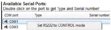
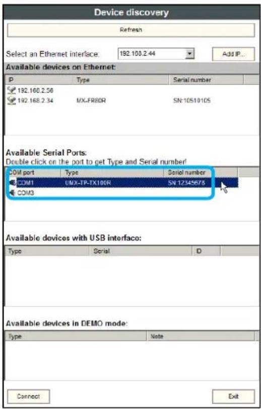
Figure 7-2. Serial connection
Step 4. Click on the Connect button to connect to the device
Info:
If the device is not listed, try searching again, or reconnect the device and restart the application.
When the Lightware Matrix Controller finds the hardware, it determines the product type, and the control menu appears. The current state of the crosspoint switch is displayed.
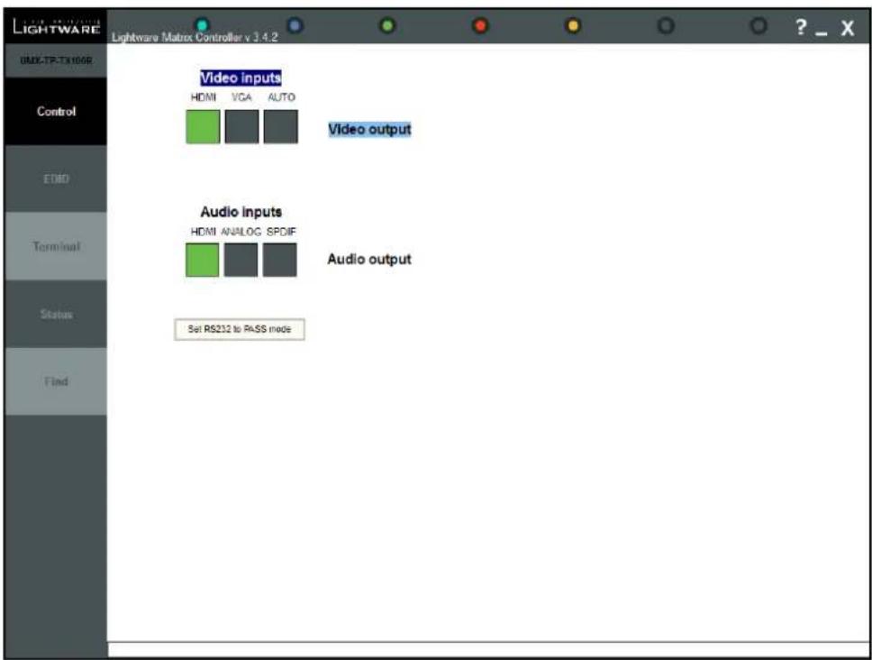
Figure 7-3. Matrix Controller crosspoint array
7.3. Control menu
This menu contains the crosspoint area. After connecting to a new device, this menu appears by default. This menu displays the current state of the device. Each green square
represents an active connection between the inputs and the output. There can be only one green square in any row.
7.3.1. Switch
For making a connection click on the desired square. Video and audio signals can be switched independently.
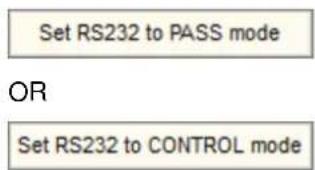
7.3.2. Toggle between the working modes
For changing the RS-232 working mode click on the button below:
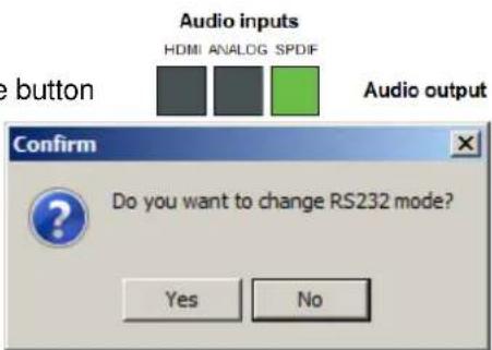
Click "Yes" in the confirmation window.
Warning! If the device was set to pass-through mode it cannot communicate with the Lightware Matrix Controller software. Before any new command for the extender the control mode must be selected again.
7.3.3. Input parameter settings
By clicking on the video inputs a dialog window appears showing the parameters for the active input.
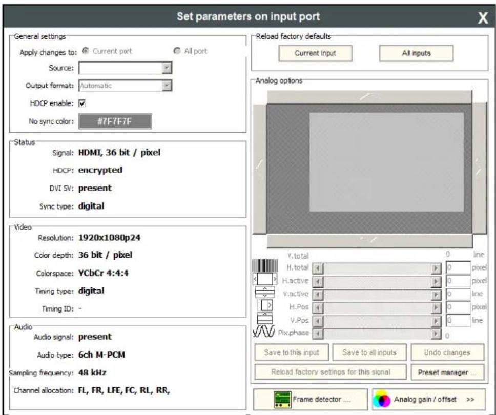
7-4. Input parameters for digital video signal
General settings
HDCP enable
The HDCP capability can be enabled or disabled on the input port with using the HDCP enable checkbox. This can prevent unnecessary HDCP encryption with certain source devices. Note that only unprotected content can be played on the source if this setting is disabled. For more information about HDCP handling see section 2.6 on page 12.
No sync color
The port generates a solid 640x480 resolution image when there is no incoming signal. The color of this picture can be set here. Double click on the colored field, a new window will appear. Choose the desired color then click the 'OK' button to apply changes. Click the Cancel button to discard changes and close the window.
Input port status
Connection status of the selected input port is shown here. (Type of the video signal, HDCP encryption, the source 5V, sync type)
Info: These fields are filled automatically by the matrix after the examination of the signal.
Video
Resolution, color depth and colorspace of the incoming signal are shown here.
The 'Timing type' and 'Timing ID' fields show which parameters are used to digitize the incoming analog signal. The input port measures the incoming analog signal and determines the timings. If the parameters need adjustment, it can be done on the right side at 'analog options'. In this case the 'Timing ID' field changes to 'user modified' unless the parameters are not saved.
Info: These fields are filled automatically by the matrix after the examination of the signal.
Audio
Information about the embedded audio signal is shown here. (Audio signal, audio type, sampling frequency, channel allocation)
Info:
These fields are filled automatically by the matrix after the examination of the signal.
Reload factory defaults
Current input: Reloads the default values to the currently selected input.
All inputs: Loads the factory default values to all inputs.
Analog video options
Analog video signals are digitized on the input. The timing parameters can be adjusted here if needed. Timing presets can be saved for each resolution separately.
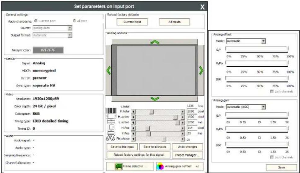
7-5. Input parameters for analog signal
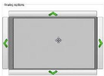
Screen position
Screen position is an easy way to fit the visible area of the analog video signal and the sink device. Actually the horizontal and vertical positions (H.Pos and V.Pos) can be set with two different methods:
natural_image
Top-down view of a rectangular device with green directional arrows indicating orientation (no text or symbols)- Click on the arrows to increase or decrease the H.Pos and V.Pos values,
OR
- Move the mouse over the visible (grey) area. Click and hold with the left mouse button. Drag the visible area to the desired position.
Analog video timings
V.total: Total line number of the whole image. (The visible and the blanking area)
H.total: Total pixel number of the whole image. (The visible and the blanking area)
H.active: Pixel number of the visible image.
V.active: Line number of the visible image.
H.Pos and V.Pos: Horizontal and vertical position values specify the location of the visible area on the sink device. Black border on any side of the picture can means wrong settings for the position of
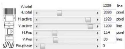
Pix.phase: In case of unclear picture changing pixel phase can solve the problem. Changing the source device or the cable can cause pixel phase shifting.
Presets
User's settings for analog video timings can be set into the UMX-TP-TX100R as presets. One preset contains the following values which can be set by the user: H.active, V.active, H.pos, V.pos and Pix.phase.
| Save to this input | Save to all inputs | Undo changes |
| Reload factory settings for this signal | Preset manager ... | |
Presets can be assigned for each different resolution to the actual or to all inputs.
Save to this input: Preset assigned for the current resolution will be set to the actual input.
Save to all inputs: Preset assigned for the current resolution will be set to all inputs.
Undo changes: Backup the last saved preset values. If there were no saved values it sets up the original settings.
Reload factory settings for this signal: Clear the saved preset for this resolution from all the inputs, and sets up the original settings.
Preset manager
User can handle the saved values with the built-in preset manager. Click on the "Preset manager..." button and a new window will open. Presets are showed for the actual input port.
Delete record from this port: Delete the selected preset from only the current port.
Delete record from all ports: Don't need to open every preset manager for each input port to delete an unwanted preset. Just click the "Delete record from all ports" button. Never mind if the selected preset has different number in the other input properties list, because the device search by the current resolution.
Clone record to all port: Don't need to reload the saved values and save to all port. It can be done with only one step. Just select the desired preset and click the "Clone record to all port" button.
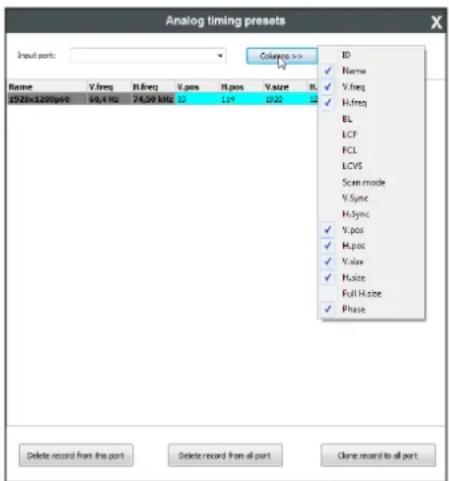
Columns: User can select which fields will be shown for the saved presets. The default fields are: Name, V.freq, H.freq, V.pos, H.pos, V.size, H.size and Phase.
Info: Analog timing presets can be saved only for the analog input port so „Delete record from all ports” and „Clone record to al port” buttons are kept for compatibility reasons.
Frame detector
Click the frame detector button to view the measured detailed timings on the incoming signal.
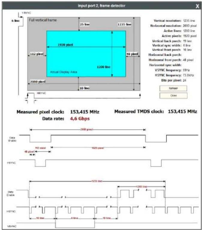
The dark grey zone is the blanking area (non-visible) and the cyan colored zone is the picture (visible area).
Info:
Resolution is given by the source devices always means the picture (visible area) resolution and the refresh rate means the VSYNC frequency.
If the Refresh button is clicked on then the UMX-TP-TX100R samples and calculates the analog signal values again.
Click on the Close button to close the Frame detector window and step back to the current input port settings window.
Analog gain / offset
Analog gain / offset window allows users to correct the gain and the offset values if the automatic mode doesn't give a good result. Gain and offset settings method are the same:
Step 1. Select the manual mode if the settings need to be changed.
Step 2. Tick the Lock channels if the three components might change with the same extent.
Step 3. Use the mouse to drag the slider and set to the desired position.
Step 4. Click on the Save button to store the changes.
Step 5. Click on the OK button when the confirmation message appears.
Step 6. Click on the Analog gain / offset button to close the window.
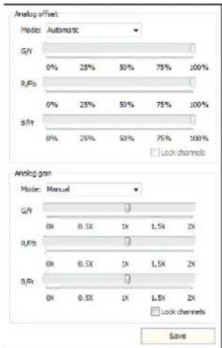
7.3.4. Output parameter settings
By clicking on the Video output label a dialog window appears showing the parameters for the corresponding output.
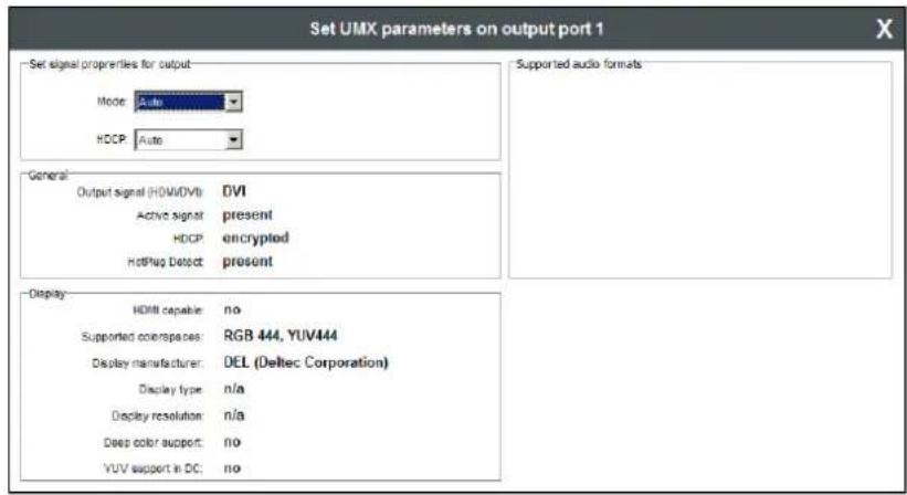
Output properties
Mode
The 'Mode' can be set to Auto, DVI, HDMI 24bit, HDMI 30bit or HDMI 36bit. The 'Auto' option sets the signal mode regarding to the attached display device's EDID and the incoming signal.
HDCP
The 'HDCP' option sets the HDCP encryption on the output. The Auto setting applies encryption when the incoming signal is encrypted. The Always setting forces encryption on any incoming video signal.
General
Information about the signal and the connection status is shown here.
Display
Information retrieved from the connected display's EDID is shown.
Supported audio formats
The connected display's supported audio formats are shown based on the read EDID.
7.4. EDID menu
Advanced EDID Management can be accessed by clicking on the EDID menu. This view is divided in two segments. The upper segment can be opened by clicking the green arrow. This segment contains the EDID editor. The lower segment is the EDID router area. This consists of two list windows, which can display a selected part of the EDID memory.
Info:
When the user enters the menu for the first time, the software starts to download the whole EDID list from the matrix. It may take about 30-40 seconds.
7.4.1. EDID Router operation
After the list is downloaded, the current status is shown. The EDID memory consists of four parts. Any memory part can be displayed on either side by using the drop down lists.
The Emulated EDID List shows the currently emulated EDIDs for each input. It contains the resolution, manufacturer and vendor name of the EDID reported to the sources for each input separately. The source column displays the memory location that the current EDID was routed from.
The Last attached Monitor's EDID List contains the resolution, manufacturer and vendor name of the display devices connected to matrix switcher's output. The matrix remembers the last display device's EDID, so there is an EDID shown even if there is no device attached to the router's output at the moment.
The Factory EDID List shows the factory memory locations (01# - 10#) with preprogrammed EDID.
The User EDID List shows the memory locations (1# - 8#) which can be used by the user to save custom EDIDs.
 text_image LIGHTWARE Lightware Matrix Controller v 3.4.2 USD TP /X1000P Advanced EDID Manager Emulated EDID List User Memory Control Inputs Manuf Resolution Monitor Name Source Input 1 DEL 1920x1200@59.94Hz DELL U2412M D001 Input 2 LWR 1920x1200@59.55Hz Univ_Analog F006 Memory Manufacturer Resolution Monitor Name 1# LWR 1920x1080@60.0Hz Univ_HDMI_ 2# LWR 1920x1080@60.0Hz Univ_HDMI_](/content/2026/06/1191477/images/9b7cfa7c58f5180304a281c0778ed62899af798b6e2598f6675f139ffec82833.jpg)
7.4.3. Easy EDID Creator
Since the above mentioned advanced editor needs more complex knowledge about EDID, Lightware introduced a wizard like interface for fast and easy EDID creation. With Lightware Easy EDID Creator it is possible to create custom EDIDs in four simple steps. By clicking on the wizard icon, the Easy EDID Creator opens in a new window.  For further information, see the user's manual of Easy EDID Creator on the Lightware website: www.lightware.com7.5. Terminal menu
 Figure 7-7. Terminal window This general-purpose serial terminal is intended mainly for testing and debugging purposes. After a successful connection is established with a router this terminal can be used via serial connection. All commands can be used here that are discussed in the Error! Not a valid bookmark self-reference., chapter 8 on page 52. The text can be typed directly. By default commands are automatically surrounded by framing brackets. Every sent command and every received response gets an arrow (-> or <-) prefix, and has different font colors in order to help distinguishing. If the "Command framing" checkbox is unchecked, you can send multiple commands together, however in this case you have to type in the framing brackets manually.7.6. Status menu
Basic device information, such as the installed boards' firmware and hardware revisions are displayed in this window.  Figure 7-8. Status menu7.6.1. Generate report file
Lightware Matrix Controller allows user to generate a standard report file which contains basic information about the health and the version numbers of the matrix. The default file name is: Lightware\_matrix\_standard\_report\_dd\_mm\_yyyy@hh\_mm.lwr User's issues can be solved easier by Lightware technical support if the generated report file was sent.  During the process a big red message will be appeared: Generating standard report... Important! Let the Lightware Matrix Controller software to finish the process! Do not exit or select another menu item. After finishing a window explorer will be opened and shown the actual folder which contains the generated report file.7.6.2. Browse command file
Lightware Matrix Controller software can run a special command file. After running the software save a result file. It is useful for debugging for the Lightware technical support. If a command file was sent: Step 1. Save it to the computer. Step 2. Click to the 'Brose command file...' button. A browser window will be opened. Step 3. Choose the command file. Another browser window will be appeared where the generated result file will be saved. Important! Let the Lightware Matrix Controller software to finish the process! Do not exit or select another menu item.  During the process a big red message will be appeared: 7.7. Find menu
By clicking this menu, the available devices can be rescanned on the serial port and on the Ethernet. If the Matrix Controller Software has a live connection to a device on a port, a question window appears, asking if you really want to search for devices. Clicking Yes will open the Find window. See section 7.2 about establishing the connection on page 39. Clicking No will close the pop up window, the original connection remains active. 8. Programmers reference
Users can connect to the extender through serial port. Lightware UMX-TP-TX100R can be controlled with external devices which can communicate according to the extender protocol.8.1. Serial port settings
UMX-TP-TX100R uses RS-232 communication port. D-SUB connector pin assignments can be found in section 4.6 on page 20. The device uses standard RS-232 interface with the following default settings: 57600 Baud, 8 data bit, 1 stop bit, no parity The serial port baud rate can be changed with protocol command. See section 8.4.2 on page 56.8.2. Protocol description
The protocol description hereinafter stands for Lightware protocol. The devices accept commands surrounded by curly brackets - {} - and responds with data surrounded by round brackets - () - only if a command was successfully executed. All input commands are converted to uppercase, but respond commands can contain upper and lower case letters as well. Legend for control commands:<in> = input number in 1 or 2 digit ASCII format (01,5,07,16 etc.)
<out> = output number in 1 or 2 digit ASCII format
<in²> = input number in 2 digit ASCII format (01, 02, 10, 12 etc.)
<out²> = output number in 2 digit ASCII format (01, 02, 10, 12 etc.)
<loc> = location number in 1, 2 or 3 digit ASCII format
<id> = id number in 1 or 2 digit ASCII format
<id²> = id number in 2 digit ASCII format
<italic> = italic parameters are optional
CrLf = Carriage return, Line feed (0x0D, 0x0A)
• = space character (0x20)
→ = each command issued by the controller
← = each response received from the router
ASCII table:
The most frequently used characters are highlighted.| Dec | Hex | Char | Dec | Hex | Char | Dec | Hex | Char | Dec | Hex | Char |
| 0 | 00 | [NUL] | 32 | 20 | [Space] | 64 | 40 | @ | 96 | 60 | ` |
| 1 | 01 | [SOH] | 33 | 21 | ! | 65 | 41 | A | 97 | 61 | a |
| 2 | 02 | [STX] | 34 | 22 | " | 66 | 42 | B | 98 | 62 | b |
| 3 | 03 | [ETX] | 35 | 23 | # | 67 | 43 | C | 99 | 63 | c |
| 4 | 04 | [EOT] | 36 | 24 | $ | 68 | 44 | D | 100 | 64 | d |
| 5 | 05 | [ENQ] | 37 | 25 | % | 69 | 45 | E | 101 | 65 | e |
| 6 | 06 | [ACK] | 38 | 26 | & | 70 | 46 | F | 102 | 66 | f |
| 7 | 07 | [BEL] | 39 | 27 | ' | 71 | 47 | G | 103 | 67 | g |
| 8 | 08 | [BS] | 40 | 28 | ( | 72 | 48 | H | 104 | 68 | h |
| 9 | 09 | [TAB] | 41 | 29 | ) | 73 | 49 | I | 105 | 69 | i |
| 10 | 0A | [LF] | 42 | 2A | * | 74 | 4A | J | 106 | 6A | j |
| 11 | 0B | [VT] | 43 | 2B | + | 75 | 4B | K | 107 | 6B | k |
| 12 | 0C | [FF] | 44 | 2C | , | 76 | 4C | L | 108 | 6C | l |
| 13 | 0D | [CR] | 45 | 2D | - | 77 | 4D | M | 109 | 6D | m |
| 14 | 0E | [SOH] | 46 | 2E | . | 78 | 4E | N | 110 | 6E | n |
| 15 | 0F | [SI] | 47 | 2F | / | 79 | 4F | O | 111 | 6F | o |
| 16 | 10 | [DLE] | 48 | 30 | 0 | 80 | 50 | P | 112 | 70 | p |
| 17 | 11 | [DC1] | 49 | 31 | 1 | 81 | 51 | Q | 113 | 71 | q |
| 18 | 12 | [DC2] | 50 | 32 | 2 | 82 | 52 | R | 114 | 72 | r |
| 19 | 13 | [DC3] | 51 | 33 | 3 | 83 | 53 | S | 115 | 73 | s |
| 20 | 14 | [DC4] | 52 | 34 | 4 | 84 | 54 | T | 116 | 74 | t |
| 21 | 15 | [NAK] | 53 | 35 | 5 | 85 | 55 | U | 117 | 75 | u |
| 22 | 16 | [SYN] | 54 | 36 | 6 | 86 | 56 | V | 118 | 76 | v |
| 23 | 17 | [ETB] | 55 | 37 | 7 | 87 | 57 | W | 119 | 77 | w |
| 24 | 18 | [CAN] | 56 | 38 | 8 | 88 | 58 | X | 120 | 78 | x |
| 25 | 19 | [EM] | 57 | 39 | 9 | 89 | 59 | Y | 121 | 79 | y |
| 26 | 1A | [SUB] | 58 | 3A | : | 90 | 5A | Z | 122 | 7A | z |
| 27 | 1B | [ESC] | 59 | 3B | ; | 91 | 5B | [ | 123 | 7B | { |
| 28 | 1C | [FS] | 60 | 3C | < | 92 | 5C | \ | 124 | 7C | | |
| 29 | 1D | [GS] | 61 | 3D | = | 93 | 5D | ] | 125 | 7D | } |
| 30 | 1E | [RS] | 62 | 3E | > | 94 | 5E | ^ | 126 | 7E | ~ |
| 31 | 1F | [US] | 63 | 3F | ? | 95 | 5F | _ | 127 | 7F | [DEL] |
8.3. Status and identification commands
8.3.1. View product type
Description: Identification of the device. Type 'i' or 'l' then the router responds its name.| Format | Example | |
| Command | {I} | → {i} |
| Response | (<PRODUCT_TYPE>)CrLf | ← (I:UMX-TP-TX100R)CrLf |
8.3.2. View serial number
Description: The extender responds its 8-digit serial number.| Format | Example | |
| Command | {S} | → {s} |
| Response | (<SERIAL_NUMBER>)CrLf | ← (SN:10170142)CrLf |
8.3.3. View Firmware version of the CPU
Description: View the CPU firmware revision.| Format | Example | |
| Command | {F} | → {f} |
| Response | (FW:)CrLf | ← (FW:1.0.9r)CrLf |
8.3.4. View installed controllers' firmware
Description: Shows the firmware revisions of the installed controllers.| Format | Example |
| Command {FC}Response (CF●END)CrLf | → {fc}← (CF END)CrLf |
8.3.5. View device's temperature
Description: Queries temperature status.| Format | Example | |
| Command | {ST} | → {st} |
| Response | (ST●)CrLf | ← (ST CPU N/A N/A N/A N/A N/A 36.2C)CrLf |
8.3.6. View CPU firmware compile time
Description: Shows the CPU firmware compile time.| Format | Example |
| Command {CT}Response (Compiled:●●Build:)CrLf | → {ct}← (Compiled:Sep 21 2012 14:06:36Build:4427)CrLf |