
RM4005A - Computer Case Black Box - Free user manual and instructions
Find the device manual for free RM4005A Black Box in PDF.

| Product Type | Rackmount Server Case |
| Model Number | RM4005A |
| Brand | Black Box |
| Form Factor | 19-inch rackmount, 1U height |
| Dimensions (W x D x H) | 17.2 x 20.0 x 1.75 inches (437 x 508 x 44 mm) |
| Weight | Approximately 12 lbs (5.4 kg) |
| Material | Steel chassis with aluminum front bezel |
| Motherboard Support | ATX, Micro-ATX, Mini-ITX |
| Drive Bays | 2 x 3.5-inch internal; 1 x 5.25-inch external |
| Expansion Slots | 1 low-profile PCIe slot |
| Power Supply Support | Standard ATX PSU (not included) |
| Cooling | 1 x 40mm exhaust fan (included); optional intake fan |
| Front I/O | 2 x USB 2.0, 1 x power button, 1 x reset button |
| Air Filters | Removable dust filter for front intake |
| Security Features | Lockable front bezel, chassis intrusion detection |
| Maintenance | Tool-less drive installation, side panel removal |
| Safety Certifications | CE, FCC, RoHS |
| Operating Temperature | 32°F to 104°F (0°C to 40°C) |
| Spare Parts Available | Replacement fans, power supply, drive caddies |
| Compliance | EIA-310-D rack mount standard |
Frequently Asked Questions - RM4005A Black Box
User questions about RM4005A Black Box
0 question about this device. Answer the ones you know or ask your own.
Ask a new question about this device
Download the instructions for your Computer Case in PDF format for free! Find your manual RM4005A - Black Box and take your electronic device back in hand. On this page are published all the documents necessary for the use of your device. RM4005A by Black Box.
USER MANUAL RM4005A Black Box
Pro Series Wallmount Cabinet
Store and secure communications equipment.
- Provides 12U of racking space.
• Supports up to 200 pounds (90.72 kg).

natural_image
Black rectangular industrial enclosure with ventilation grilles and a closed door (no visible text or symbols)Trademarks Used in this Manual
Black Box and the Double Diamond logo are registered trademarks of BB Technologies, Inc.
Any other trademarks mentioned in this manual are acknowledged to be the property of the trademark owners.
Disclaimer:
Black Box Network Services shall not be liable for damages of any kind, including, but not limited to, punitive, consequential or cost of cover damages, resulting from any errors in the product information or specifications set forth in this document and Black Box Network Services may revise this document at any time without notice.
We're here to help! If you have any questions about your application or our products, contact Black Box Tech Support at 724-746-5500 or go to blackbox.com and click on "Talk to Black Box."
You'll be live with one of our technical experts in less than 60 seconds.
Federal Communications Commission and Industry Canada Radio Frequency Interference Statements
This equipment generates, uses, and can radiate radio-frequency energy, and if not installed and used properly, that is, in strict accordance with the manufacturer's instructions, may cause interference to radio communication. It has been tested and found to comply with the limits for a Class A computing device in accordance with the specifications in Subpart B of Part 15 of FCC rules, which are designed to provide reasonable protection against such interference when the equipment is operated in a commercial environment. Operation of this equipment in a residential area is likely to cause interference, in which case the user at his own expense will be required to take whatever measures may be necessary to correct the interference.
Changes or modifications not expressly approved by the party responsible for compliance could void the user's authority to operate the equipment.
This digital apparatus does not exceed the Class A limits for radio noise emission from digital apparatus set out in the Radio Interference Regulation of Industry Canada.
- Specifications....6
- Overview....7
2.1 Description 7
2.2 Features....7
2.3 What's Included 7
2.4 Optional Accessories....8
2.4.1 Fan Tray (RM4002A) 8
2.4.2 Filter Tray (RM4003A) 8
2.4.3 Blanking Panel (RM4004A) 8
2.4.4 Extra Vertical Rails (RM4005A)....8
2.4.5 45° Rear Mounting Rails (RM4006A) 9
2.4.6 Shelf, 10-inch (RM4007A)....9
- Installation....10
3.1 Wallmounting the Cabinet .... 10
3.2 Connecting the 45° Rails to the Cabinet After It's Mounted on the Wall ....12
- Troubleshooting....13
4.1 Contacting Black Box....13
4.2 Shipping and Packaging....13
1. Specifications
RM4001A Cabinet
| Finish Black | |
| Hole-to-Hole Centers 18.3" (48.3 cm) | |
| Material Front Door: 18-gauge (1.2-mm) steel;Rear Body: 14-gauge (2.0-mm) steel | |
| Dimensions Exterior Width: 24" (61 cm);Exterior Depth: 30" (76.2 cm);Interior Width: 23.75" (60.3 cm);Interior Depth: 28" (71.1 cm);Maximum Mounting Depth: 22" (55.8 cm) | |
| Weight Capacity 200 lb. (90.72 kg) | |
| Rack Units 12U | |
| Weight 94 lb. (42.6 kg) | |
| RM4002A Fan Tray | |
| Air Flow 46/53 CFM per fan | |
| Bearing Type Ball bearing | |
| Construction 18-gauge steel (1.2 mm) | |
| Fan Speed 1600/2000 RPM | |
| Finish Black | |
| Noise 31/33 dBA | |
| Power 115 VAC, 60 Hz | |
| Dimensions Each: 1.75"H x 12.25"W x 6.25"D (4.5 x 31.2 x 15.9 cm) | |
| Weight 1 lb. (0.5 kg) | |
| RM4003A Filter Tray | |
| Dimensions 5.5"H x 12.25"W x 1.5"D (14 x 31.2 x 1.3 cm) | |
| Weight 0.9 lb. (0.4 kg) | |
| RM4004A Blanking Panel | |
| Dimensions 5.5"H x 12.25"W x 0.25"D (14 x 31.2 x 0.6 cm) | |
| Weight 1 lb. (0.5 kg) | |
| RM4005A Extra Rails | |
| Number of Rack Units | 12U high |
| Weight 2.8 lb. (1.3 kg) | |
| RM4006A 45° Brackets | |
| Dimensions 4.1"H x 1.4"W x 4"D (10.4 x 3.6 x 10.2 cm) | |
| Weight 0.6 lb. (0.3 kg) | |
| RM4007A Shelf, 10-inch (25.4-cm) | |
| Dimensions 3.5"H x 19"W x 10"D (8.9 x 48.3 x 25.4 cm) | |
| Weight 4.7 lb. (2.1 kg) | |
2. Overview
2.1 Introduction
The Pro Series Wallmount Cabinet holds deep rackmountable equipment. It has adjustable rails for mounting equipment away from the front door while still providing proper cable management in the front and rear of the cabinet.
The cabinet's rear door has several cable access holes. Vented sides enable proper airflow. Plus, the front and rear door are reversible.
You can install up to 200 pounds (90.72 kg) of equipment in the cabinet.
2.2 Features
- 19" rackmount width
- Rounded corners and edges on front door for safety
- Swing-out body for access to the back of installed equipment
- Knockouts sized for 21/ " conduit fittings
- Vented side panels for airflow
- Includes one pair of adjustable depth 19" mounting rails
2.3 What's Included
Your package should include the following items. If anything is missing or damaged, please contact Black Box Technical Support at 724-746-5500 or info@blackbox.com.
RM4001A:
• Wallmount Cabinet
• (1) pair of adjustable depth 19" mounting rails (installed)
• (20) M5 cage nuts
• (20) M5 x 15 cuphead screws
• (8) 1/ " x 2" hexagonal screws
- Mounting template
• (2) pairs of door keys
RM4002A:
- Fan tray assembly
• (4) screws
• (4) nuts
RM4003A:
- Filter tray
• (4) screws
• (4) nuts
RM4004A:
- Blanking panel
• (4) screws
• (4) nuts
RM4005A:
• (2) extra vertical rails
• (4) M5 hexhead screws
• (4) M5 cage nuts
RM4006A:
• (2) 45-degree rails
• (4) nuts
RM4007A:
- 10-inch shelf
• (4) cuphead screws
• (4) cage nuts
PRO SERIES WALLMOUNT CABINET
2.4 Optional Accessories
2.4.1 Fan Tray (RM4002A)
This fan tray provides additional airflow in the cabinet. It mounts on the cabinet's inside side panel. The fan tray has a sticker that shows the airflow direction as configured from the factory.
You can reverse the airflow in the fan tray by removing the two front filter covers, loosening the eight screws, removing the fans and reinstalling them in the opposite-flow position, then reinstalling the eight screws and cover.
2.4.2 Filter Tray (RM4003A)
This internally mounted filter tray blocks out dust and damaging air particles.
NOTE: The filter is NOT NEMA rated.
2.4.3 Blanking Panel (RM4004A)
This is a cover to block one of the side panel ventilation access holes. It mounts on the inside of the cabinet.
2.4.4 Extra Vertical Rails (RM4005A)
Using the included four screws and four cage nuts, this set of two additional internally mounted rails enable you to mount two different pieces of equipment that have different mounting requirements.
2.4.5 45° Rear Mounting Rails (RM4006A)
The RM4006A includes two 45° mounting rails. These rails mount on two of the 12 studs welded into the rear door of the wall-mount cabinet. Install rackmount equipment onto these rails. This keeps the space free in the front of the cabinet.
Section 3.2 describes how to attach the rear mounting rails after the cabinet's attached to the wall.
2.4.6 Shelf, 10-inch (RM4007A)
Using the included four screws and four nuts, this small 10-inch shelf mounts in the front of the cabinet to enclose non-rackmountable equipment in the cabinet.
3. Installation
3.1 Wallmounting the Cabinet
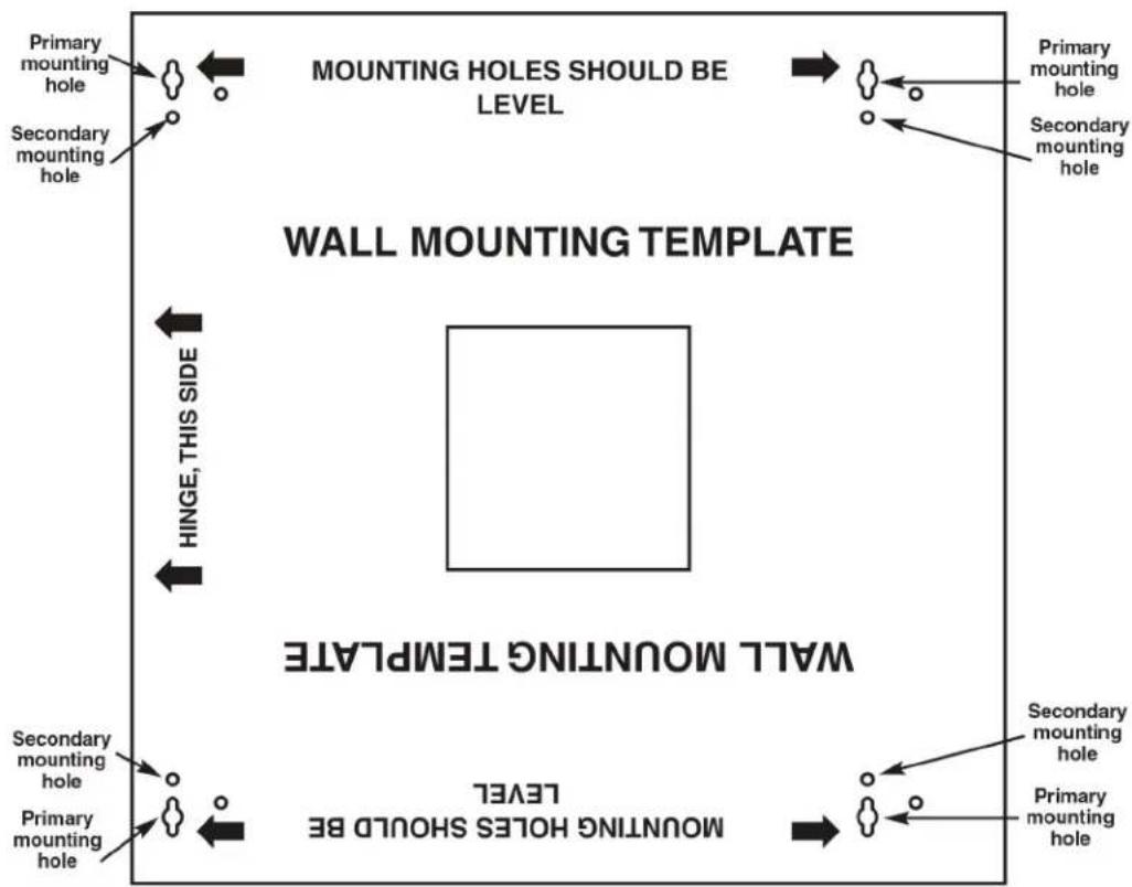
Use the template shown in Figure 3-1 to wallmount the cabinet. Follow the steps listed below:
- Remove the mounting template from the packaging.
- Select either a left-side or right-side hinge orientation for the front door.
- Find wall studs and position the template on the wall.
- Use a level to check the mounting hole positioning on the wall.
-
Mark the primary mounting hole positions on the wall with a pencil.
-
Drill (4) 1/4" x 2" hexagonal screws into the wall through the primary mounting holes, leaving about 1/8" gap between the wall and the hex screw head.
flowchart
graph TD
    A["Primary mounting hole"] --> B["WALL MOUNTING TEMPLATE"]
    C["Secondary mounting hole"] --> B
    D["Primary mounting hole"] --> B
    E["Secondary mounting hole"] --> B
    F["Primary mounting hole"] --> G["WALL MOUNTING TEMPLE"]
    H["Secondary mounting hole"] --> G
    I["Primary mounting hole"] --> G
    J["Secondary mounting hole"] --> G
    K["Primary mounting hole"] --> G
    L["Secondary mounting hole"] --> M["MOUNTING Holes SHOULD BE LEVEL"]
    N["Hinge, THIS SIDE"] --> B
    O["MOUNTING Holes SHOULD BE LEVEL"] --> G
    P["MOUNTING Holes SHOULD BE LEVEL"] --> G
    Q["Primary mounting hole"] --> R["MOUNTING TEMPLE"]
    S["Secondary mounting hole"] --> R
    T["Primary mounting hole"] --> R
Figure 3-1. Wallmounting template.
- Position the cabinet with its primary mounting holes flush against the wall. Hang the cabinet on the hex screw heads. Refer to Figure 3-2.
- Tighten the hexagonal screw heads.
- Drill (4) 1/4" x 2" hexagonal screws into the wall through the secondary mounting holes.
- Tighten the hexagonal screw heads.
Figure 3-2. Mounting the cabinet on the wall.
3.2 Connecting the 45° Rails to the Cabinet After It's Mounted on the Wall
- Line up the mounting holes on the rails with the studs that are welded to the back of the cabinet.
- Hang one rail from the pair on two studs on one side of the cabinet.
- Hang the other rail from the pair on two studs on the other side of the cabinet.
- Install (2) M5 nuts to the studs to secure each 45^ rail to the cabinet.
- For each pair of rails that you want to install, repeat steps 1–4. You can install up to two pairs of rails.
NOTE: The diagram below shows two pairs of 45^ rails mounted in the cabinet.
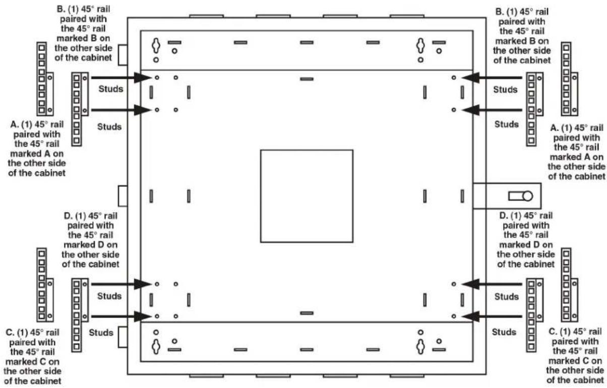
Figure 3-3. Installing two pairs of 45^ rails on cabinet after it's mounted to the wall.
NOTE: For details about other optional accessories, see Section 2.4.
4. Troubleshooting
4.1 Contacting Black Box
If you determine that your Pro Series Wallmount Cabinet is malfunctioning, do not attempt to alter or repair the unit. It contains no user-serviceable parts. Contact Black Box Technical Support at 724-746-5500 or info@blackbox.com.
Before you do, make a record of the history of the problem. We will be able to provide more efficient and accurate assistance if you have a complete description, including:
- the nature and duration of the problem.
- when the problem occurs.
- the components involved in the problem.
- any particular application that, when used, appears to create the problem or make it worse.
4.2 Shipping and Packaging
If you need to transport or ship your Pro Series Wallmount Cabinet:
- Package it carefully. We recommend that you use the original container.
- If you are returning the unit, make sure you include everything you received with it. Before you ship for return or repair, contact Black Box to get a Return Authorization (RA) number.
Black Box Tech Support: FREE! Live. 24/7.
Tech support the way it should be.

natural_image
Close-up portrait of a smiling man with short hair holding a small object, against a blue gradient background (no text or symbols visible)Great tech support is just 60 seconds away at 724-746-5500 or blackbox.com.

BLACK BOX®
About Black Box
Black Box provides an extensive range of networking and infrastructure products. You'll find everything from cabinets and racks and power and surge protection products to media converters and Ethernet switches all supported by free, live 24/7 Tech support available in 60 seconds or less.
© Copyright 2014. Black Box Corporation. All rights reserved. Black Box ^® and the Double Diamond logo are registered trademarks of BB Technologies, Inc. Any third-party trademarks appearing in this manual are acknowledged to be the property of their respective owners.
RM4001A version 2
- Pro Series Wallmount Cabinet
- Store and secure communications equipment.
- Trademarks Used in this Manual
- Disclaimer:
- Federal Communications Commission and Industry Canada Radio Frequency Interference Statements
- Specifications
- Overview
- Introduction
- Features
- What's Included
- RM4001A:
- RM4002A:
- RM4003A:
- RM4004A:
- RM4005A:
- RM4006A:
- RM4007A:
- Optional Accessories
- Fan Tray (RM4002A)
- Filter Tray (RM4003A)
- Blanking Panel (RM4004A)
- Extra Vertical Rails (RM4005A)
- 45° Rear Mounting Rails (RM4006A)
- Shelf, 10-inch (RM4007A)
- Installation
- Wallmounting the Cabinet
- Connecting the 45° Rails to the Cabinet After It's Mounted on the Wall
- Troubleshooting
- Contacting Black Box
- Shipping and Packaging
- Black Box Tech Support: FREE! Live. 24/7.
- BLACK BOX®
- About Black Box
Brand : Black Box
Model : RM4005A
Category : Computer Case