SPM180K - Solar panels Projecta - Free user manual and instructions
Find the device manual for free SPM180K Projecta in PDF.

User questions about SPM180K Projecta
0 question about this device. Answer the ones you know or ask your own.
Ask a new question about this device
Download the instructions for your Solar panels in PDF format for free! Find your manual SPM180K - Projecta and take your electronic device back in hand. On this page are published all the documents necessary for the use of your device. SPM180K by Projecta.
USER MANUAL SPM180K Projecta
- For installations with lead acid batteries, avoid sparks or flames near the batteries and always use proper eye protection
- Given sufficient light, solar panels always generate energy even when they are disconnected
- Accidental 'shorting' of the terminals or wiring can result in sparks causing personal injury or a fire hazard
- Do not scratch or bend solar panels
- Do not disassemble the solar panel
- When mounting solar panels at a height adhere to all relevant safety regulations
- Do not walk on modules
- Do not attempt to increase module output by concentrating light on its surface with mirrors
- Be sure to use components (cables, fuses, etc) greater than 25% of solar panel's maximum current ratings
- When storing the Solar panel kit do not pack heavy items on top the Solar panel and bag
- Do not disassemble the controller. Take to a qualified person if the unit requires repairing
FEATURE OVERVIEW
SOLAR PANEL
Compact and Powerful – Monocrystalline solar panels are manufactured from a solar cell that is cast from silicon. These cells are more efficient at producing power than amorphous panels, so the size of the panel is smaller yet produces greater output power
Lightweight, Foldable Design – Folds up into a self contained 38cm x 56cm bag for easy storage
Scratch Resistant – Panels feature a scratch resistant mat coating for durability
5m Lead & Battery Clips – Fused battery lead makes for trouble free battery connection.
Front pocket for easy storage
Heavy Duty Canvas – Tough canvas material suitable for camping and off-road environments
Metal Support Legs – Legs keep the panels at the optimum angle for maximum performance
Collapsible Tent Pole – The pole feeds through the sewn in loops to keep the panel rigid when set-up
Reinforced Eyelets – Reinforced eyelets allow you to secure the panels using tent pegs, or hang the panels vertically
SPECIFICATIONS
| P/No. | SPM180K |
| TYPE MONOCRYSTALLINE | |
| RATED POWER 180W | |
| OPEN CIRCUIT VOLTAGE 21V | |
| SHORT CIRCUIT CURRENT 11.0A | |
| PEAK POWER VOLTAGE 18.0V | |
| PEAK POWER CURRENT 10.3A | |
| TEST CONDITIONS 1000W/m2, 25°C | |
| FUSE 15.0A | |
| BATTERY CONNECTIONS Battery Clamps | |
| WEIGHT 8.3kg |
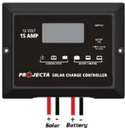
SOLAR CONTROLLER
Advanced MCU – Features control pulse width modulated (PWM) technology, high efficiency operation.
Multi-Chemistry – Target for Gel, AGM, Conventional lead-acid (WET) and Calcium Batteries.
4 Stage Charging – Built in regulator to prevent your battery from being overcharged. Overcharging occurs when the charge voltage is unregulated. This can result in premature battery failure.
The regulator also prevents your battery from being under charged, in the solar energy field, battery undercharge always occurs, especially on some Conventional lead – acid or Calcium batteries; The unit provides an automatic Equalization feature for deeply drained Conventional lead acid batteries or Calcium batteries, as well as provides a cycling automatic Equalizing feature every 28 days.
It keeps the battery fully charged by using a process called “floating”. This means the controller will stop charging when the battery is full and will automatically start charging the battery as required. This process will also reduce water loss and help prevent the battery from ‘drying out’.
Discharge Protection – Protects your battery from discharge at night. Under low light or no light conditions the solar panel voltage could be less than the battery voltage. The unit contains a special circuit which prevents current flowing back from the battery and into the solar panel.
LED Indicators – Coloured LED's to easily indicate the operational status and battery conditions.
Digital LCD – Directly display battery voltage, charging current, charging capacity (Amp hour), battery types, full charge and faulty codes.
Daily Amp hour (Ah) Meter – Takes a reading of the accumulated energy (Ah) and can be displayed at the push of a button (Volt/Amp). The meter resets when the solar panels are inactive or disconnected/reconnected to the battery.
Unit Protection – Multi charging protects against reverse polarity, short circuit, over temperature, over voltage, etc.
Voltage Compensation – Automatically measures the voltage drop from the output lead and self adjusts to maximise the charge for the 5m supplied cable.
Please check your battery manufacturer's specifications to select correct battery type. The unit provides 4 battery types for selections: Gel, AGM, WET (conventional lead acid), and Calcium.

Press BATTERY TYPE button and hold for 3 seconds to go into your battery type selection mode, the battery type you select will be shown on the LCD meter, the default setting is AGM Battery; the controller will automatically memorize your battery type setting.
Caution: Incorrect battery type setting may damage your battery.
When the controller powers on, the unit will run 'self-qualify' mode and automatically show below items on LCD before going into charging process
Self-test starts, digital meter segments test
Software version test
18.0 *Rated voltage and current test
After going into charging process, the LCD displays the charging statues as below: Press VOLT / AMP button in sequence, the LCD will display in turn with Battery Voltage, Charging Current and Charged capacity (Amp-hour)
Display in the day time:

Display during the night:
8.8 v Ah
Display when battery fully charged
Press VOLT / AMP button in sequence, the LCD will display in turn with Battery Voltage, Charging Current, if you do not press the button, the LCD will alternatively display the FUL and VOLT or FUL and AMP every 2 seconds.

chemical
Chemical reaction diagram showing conversion of 8.8 to 8.00 at 6°C, then to 8.00 at 8A and 8.00 at 6CCHARGING STAGES
The VOLT / AMP button can be changed at any time during charging process.
The LCD also can be treated as an independent voltage meter. A voltage less than 11.5V Volts indicates that the battery is discharged and needs re-charging.
flowchart
graph LR
    A["Level 1"] --> B["Level 2"]
    B --> C["Level 3"]
    C --> D["Level 4"]
    D --> E["Level 5"]
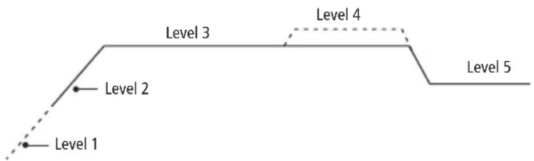
Soft Charge – When batteries suffer an over-discharge, the controller will softly ramp the battery voltage up to 10V.
Bulk Charge – Maximum current charging until batteries rise to Absorption level
Absorption Charge – Constant voltage charging and battery is over 85%.
Equalization Charge – Only for WET battery or Calcium battery type, when the battery is deeply drained below 10V, it will automatically run this stage to bring the internal cells as an equal states and fully complement the loss of capacity.(Gel and AGM battery do not run Equalization charge)
Float Charge – Battery is fully charged and maintained at a safe level. A fully charged battery has a voltage of more than 13.6 Volts.
OPERATION – L.E.D. INDICATION
| The 6 LED's indicate the charging status and the battery condition | Red Blue | Green Green | Yellow | Red | ||
| Solar Power Present - ON OFF OFF No battery connected | OFF OFF | Flash | ||||
| Soft charging | ON Flash | OFF OFF | OFF | ON | ||
| Bulk charging | ON | ON | OFF | Subject to battery voltage | ||
| Absorption charging | ON | ON | OFF | ON | OFF | OFF |
| Equalization charging | ON | ON | OFF | ON | OFF | OFF |
| Float charging | ON OFF | ON | OFF OFF | OFF | ||
| Solar panel weak | Flash | OFF | OFF | Subject to battery voltage | ||
| At night no charge | OFF | OFF | OFF | Subject to battery voltage | ||
| Battery Voltage below 11.5V (+/-0.2V) | ON | ON | OFF | OFF | OFF | ON |
| Battery Voltage between 11.5V - 12.5V(+/-0.2V) | ON | ON | OFF | OFF | ON | OFF |
| Battery Voltage above 12.5V (+/-0.2V) | ON | ON | OFF | ON | OFF | OFF |
Note: LEDs will turn off during insufficient sunlight.
ABNORMAL OPERATION MODE
| Solar panel abnormal mode LCD display | LED indication | LCD backlight | |
| Solar panel weak | Flash ON | ||
| Solar panel reverse connection |  | Flash Flash | |
| Solar panel over voltage (>26.5V) |  | Flash | Flash |
| Battery abnormal mode LCD display | LED indication | LCD backlight | |
| Battery disconnected or less than 3.0V |  | Flash Flash Flash | Flash |
| Battery reverse connection |  | Flash | Flash |
| Battery over voltage than >17.5V |  | Flash | Flash |
| Solar controller abnormal mode LCD display | LED indication | LCD backlight | |
| The controller over temperature protection |  | Flash |
SOLAR CONTROLLER SPECIFICATIONS
| 1 Electrical Parameters | ||||
| 1-1 Rated solar panel amps | 15 | Max. | AMP | |
| 1-2 Normal input Solar cell array voltage | 15–22 | VDC | ||
| 1-3 Max. solar cell array voltage (output has no load) | 25 | Max. | VDC | |
| 1-4 The controller lowest operating voltage (at solar or battery side) | 8V | Min | VDC | |
| 1-5 Standby current consumption at night | 5 | Max | mA | |
| 1-6 Maximum voltage drop-Solar panel to battery | 0.25 | Max. | VDC | |
| 2 Charging characteristics | ||||
| 2-1 Minimum battery start charging voltage | 3 | Min | VDC | |
| 2-2 Soft start charging voltage | 3-10 | +/-0.2 | VDC | |
| 2-3 Soft start charging current (50% PWM duty) | Up to 15 | AMP | ||
| 2-4 Bulk charge voltage 10-14.0 +/-0.2 VDC | ||||
| 2-5 Absorption charging voltage at 25°C | ||||
| • Gel type battery | 14.1 | +/-0.2 | VDC | |
| • AGM type battery (default setting) | 14.4 | +/-0.2 | VDC | |
| • WET type battery | 14.7 | +/-0.2 | VDC | |
| • Calcium type battery | 14.9 | +/-0.2 | VDC | |
| 2-6 Absorption transits to Equalizing or Float condition: | ||||
| • Charging current drops to | 0.5 | +/-0.1 | AMP | |
| • or Absorption charging timer timed out | 4 | Hour | ||
| 2-7 Equalization charging active | ||||
| • Only for WET or Calcium battery | ||||
| • Battery voltage discharged to less than | 10 | +/-0.2 | VDC | |
| • Automatic equalizing charging periodical | 28 | Day | ||
| 2-8 Equalization charging voltage | 15.5 | +/-0.2 | VDC | |
| 2-9 Equalization charging timer timed out | 2 | Hour | ||
| 2-10 Float charging voltage | 13.6 | +/-0.2 | VDC | |
| 2-11 Voltage control accuracy | +/- 1% | |||
| 3 Protection | ||||
| 3-1 Against reverse polarity or short circuit at panel side | ||||
| 3-2 Against reverse polarity or short circuit at battery side | ||||
| 3-3 No reverse current from battery to solar at night | ||||
| 3-4 Over temperature protection during charging 65 | °C | |||
| 3-5 Transient over voltage protection with TVS or varistor | ||||
| 4 Electrical parts | ||||
| 4-1 Input output terminal M4 terminals | ||||
| 4-2 Temperature sensor port (Press and Release type) DA 250-350 2P | ||||
| 5 Physical Parameters | ||||
| 5-1 Controller material Plastic, Standard ABS | ||||
| 5-2 Power terminal maximum stranded wire size #12 AWG stranded-3 mm ^2 | ||||
| 5-3 Mounting | Vertical wall mounting | |||
| 5-4 IP grade | IP22 | |||
| 5-5 Net weight Approx. | 250g | |||
| 6 Environmental characteristics | ||||
| 6-1 Operating temperature | -25 ~ 50 °C | |||
| 6-2 Storage temperature | -40 ~ 85 °C | |||
| 6-3 Operating Humidity range | 100% no condensation | |||
INSTALLATION & CONNECTION
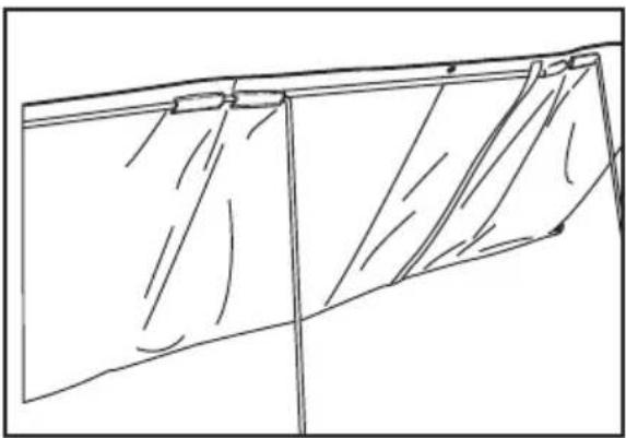
STEP 1 Locate the panel in the best position
Locate the panel in a position where it is exposed to the sun for the majority of the day. For Best results use a northern orientation. The panel will function in the horizontal or hung position, however for best performance tilt the panels so they directly face the sun.
natural_image
Line drawing of a folded garment or fabric with diagonal folds and a vertical seam (no text or symbols)A. For stability feed the supplied collapsible tent pole through the canvas loops
B. Insert metal support legs into the canvas loops along the top of the panels
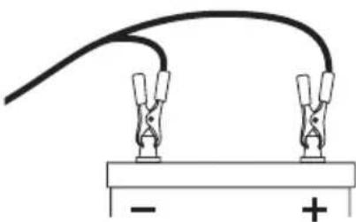
STEP 2 Connect to the battery
Connect the 5 meter lead to the battery, Red clamp to the positive (+) terminal and Black clamp to the negative (-) terminal. The solar panel will now be charging the battery. Refer to Solar Controller Instructions, 'Operation – L.E.D Indication' (page 4) for further details of charging status.
natural_image
Simple electrical circuit diagram showing two clamps connected to a battery with positive and negative terminals (no text or symbols)STEP 3 Secure the solar panel to the ground
Secure by pushing the legs into the ground. For greater set-up stability secure the panel to the ground by using tent pegs which can be fed through the eyelets of the solar panel and through the holes at the lower end of the supplied legs.
MAINTENANCE
Periodically inspect the electrical and mechanical connections. Make sure they are all tight and free from corrosion. If necessary clean the surface of the solar panels with a soft dump cloth. Mild detergent can also be used. Any dirt or residue on the PVC may effect performance.
FREQUENTLY ASKED QUESTIONS
Q. Can the solar panel be mounted on a flat roof or wall?
A. Yes. It is fine to mount the panel on a horizontal surface such as a roof or on a vertical surface like a wall as long as the panel receives full sun for a reasonable period of the day. You will however gain better performance if the panel is tilted toward the sun and faced in a northerly direction, since this enables the maximum amount of solar energy to reach the panel.
Q. What current output can I expect?
A. The current output (mA) of the solar panel is based mostly on the available solar energy (sun rays). The current ratings (Peak Power) given in the specifications table are based on the 'ideal' sunlight conditions. In reality this may be achieved only on a very bright sunny day. The normal current output will therefore be a little lower. If the panel is shaded or if it is a very hot day the output will decrease further.
Q. Will it charge my flat battery & how long will it take?
A. The SPM180K with charge a flat battery (above 9V) 250-1800CCA (Automotive) with a charge time of 7-35Hrs.
Q. I am going on a 4WD trip, will 180 Watts be enough?
A. It really comes down to how many appliances are drawing power from your battery.
For example:
Most people when they go away would run a Fridge, and a couple of lights to cook with etc.
We need to work out how much power would be used in a day.
Energy consumption per day
If we say we get around 10 hours of solar energy from the panels per day (for summer months).
We can then calculate what size and how many panels we need.
45 amps ÷ 10 hours = 4.5 Amps per hour
| Appliance Current use/hour (Ah) Total time of use/day (Hours) Total Current per day (Amps) | |||
| Fridge 1.5 24 | 36 | ||
| 3 Lights 3 3 9 | |||
| Grand Total | 45 | ||
So the SPM180K solar panel kit can produce 11.0 Amps an hour, this is well and truly more than enough. You might find that during cloudy weather you will have to charge the battery by running your car for half an hour every second or third day.
WARRANTY STATEMENT
Applicable only to product sold in Australia
Brown & Watson International Pty Ltd of 1500 Ferntree Gully Road, Knoxfield, Vic., telephone (03) 9730 6000, fax (03) 9730 6050, warrants that all products described in its current catalogue (save and except for all bulbs and lenses whether made of glass or some other substance) will under normal use and service be free of failures in material and workmanship for a period of one (1) year (unless this period has been extended as indicated elsewhere) from the date of the original purchase by the consumer as marked on the invoice. This warranty does not cover ordinary wear and tear, abuse, alteration of products or damage caused by the consumer.
To make a warranty claim the consumer must deliver the product at their cost to the original place of purchase or to any other place which may be nominated by either BWI or the retailer from where the product was bought in order that a warranty assessment may be performed. The consumer must also deliver the original invoice evidencing the date and place of purchase together with an explanation in writing as to the nature of the claim.
In the event that the claim is determined to be for a minor failure of the product then BWI reserves the right to repair or replace it at its discretion. In the event that a major failure is determined the consumer will be entitled to a replacement or a refund as well as compensation for any other reasonably foreseeable loss or damage.
This warranty is in addition to any other rights or remedies that the consumer may have under State or Federal legislation.
IMPORTANT NOTE
Our goods come with guarantees that cannot be excluded under the Australian Consumer Law. You are entitled to a replacement or refund for a major failure and compensation for any other reasonably foreseeable loss or damage. You are also entitled to have the goods repaired or replaced if the goods fail to be of acceptable quality and the failure does not amount to a major failure.
Distributed by
AUSTRALIA
Brown & Watson International Pty Ltd
Knoxfield, Victoria 3180
Telephone (03) 9730 6000
Facsimile (03) 9730 6050
National Toll Free 1800 113 443
NEW ZEALAND
Narva New Zealand Ltd
22–24 Olive Road
PO Box 12556 Penrose
Auckland, New Zealand
Telephone (09) 525 4575
Facsimile (09) 579 1192