
BT7087 - Wall mount B-Tech - Free user manual and instructions
Find the device manual for free BT7087 B-Tech in PDF.

| Type | Wall mounted AV shelf |
| Brand | B-Tech |
| Model | BT7087 |
| Color | Black |
| Material | Black metal frame, tempered glass shelf |
| Glass shelf dimensions | 470mm (18.5") x 310mm (12.2") x 10mm (0.4") |
| Cable hole size | 40mm (1.5") x 20mm (0.7") |
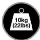
| Weight capacity | 10 kg (22 lbs) |
| Compatible devices | DVD/Blu-Ray players, satellite receivers, games consoles |
| Feet type | 4 polished alloy feet with non-slip rubber inlays |
| Safety standard | Meets British Standard BS6206 |
| Installation wall types | Brick/concrete or wood/stud walls |
| Included hardware | Wall plate, shelf support, glass shelf, support feet, M5 grub screws, M8 hex screws, double-sided pads, single-sided pads, wall plugs, coach screws, hex keys |
| Optional accessories | B-Tech cable management systems |
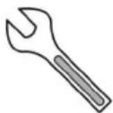
| Tools required | 13mm spanner, drill, 10mm masonry bit or 6mm wood bit, pencil, stud finder (optional) |
| Package contents | 1 wall mount shelf |
| Warranty | Not specified; see manual for details |
| Country of origin | Made in China |
Frequently Asked Questions - BT7087 B-Tech
User questions about BT7087 B-Tech
0 question about this device. Answer the ones you know or ask your own.
Ask a new question about this device
Download the instructions for your Wall mount in PDF format for free! Find your manual BT7087 - B-Tech and take your electronic device back in hand. On this page are published all the documents necessary for the use of your device. BT7087 by B-Tech.
USER MANUAL BT7087 B-Tech
This Pack Contains 1 Mount
PLEASE KEEP THIS FOR FUTURE REFERENCE
mountlogic® range

natural_image
Black metal frame with a triangular support and mounting bracket, mounted on a rectangular base (no text or symbols visible)
COMPATIBLE
REG DESIGN NO: 4003647
FEATURES
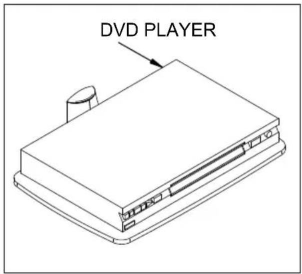
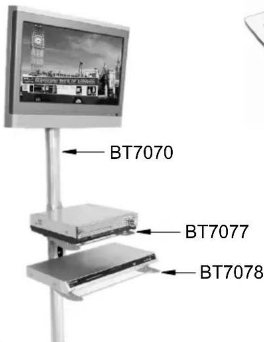
- Wall mounted shelf designed to hold DVD / Blu-Ray players, satellite receivers and games consoles up to 10kg (22lbs)
- Stylish design integrates with B-Tech cable manager for smart AV installations
• Supplied with 4 polished alloy feet and non slip rubber inlays - Can be used as a stand alone unit
- Glass shelf dimensions: 470mm (18.5") x 310mm (12.2") x 10mm (0.4")
- 40mm (1.5") x 20mm (0.7") cable hole
- Simple installation with all mounting hardware included
• Meets British standard BS6206

CAUTION!! GLASS
This item contains glass - Handle with care to avoid damage or injury
CONTENTS
Installation Safety Notes....2
Parts List....4
Installation Instructions....6
Optional Accessories....10
Product Dimensions....11
B-Tech Contact Details....12
INSTALLATION TOOLS REQUIRED
13mm (1/2") spanner or socket
Drill
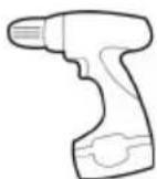
10mm (7/16") masonry bit or 6mm (1/4") wood bit

Pencil

Stud finder (optional)
B-TECH AUDIO VIDEO MOUNTS
www.btechavmounts.com
INSTALLATION SAFETY INSTRUCTIONS

CAUTION: This shelf is intended for use only with the maximum weights indicated. Use with AV equipment heavier than the maximum indicated may result in instability causing possible injury.
Do not attempt to install this product until all instructions and warnings have been read and properly understood. Please keep these instructions for future reference.
B-Tech International Limited, its distributors and dealers are not liable or responsible for damage or injury caused by improper installation, improper use or failure to observe these safety instructions. In such cases, all guarantees will expire.
General
Great care must always be taken during installation as most AV equipment is of a fragile nature, possibly heavy and easily damaged if dropped.
If you do not fully understand the instructions or are not sure how to install this product safely, then please consult a professional for advice and/or to install this product for you. Failure to mount this product correctly may cause serious injury or death both during installation and at any time thereafter.
Do not mount any AV equipment that exceeds the specific weight limit of the product you are installing. This weight limit will be clearly stated on each product and its packaging and will vary from product to product.
Product location
Please pay careful attention to where this product is located. Some locations are not suitable for installation.
If located in a public or frequently populated area ensure that the product is out of the immediate reach of people.
Fixing hardware
It is highly recommended that all fixing screws be used where supplied and that the purpose of all other fixing hardware is fully understood. In some cases more AV equipment fixing hardware will be supplied to accommodate different models of equipment and set up configurations.
The installer must be satisfied that any supplied fixing hardware is suitable for each specific installation. If any fixing screws or included hardware are deemed not sufficient for a safe installation then please consult a professional or your local hardware store.
Hazard limitation
When routing cables take advantage of any built in cable management features that the product might provide and ensure that all cables are tidy and secure. Check to see that any moving aspect of the product can do so unhindered by any cabling.
Some products have moving parts and the potential to cause injury through the crushing or trapping of fingers or other body parts.
Particular attention to the nature of moving parts is required especially when assembling installing and adjusting during set up.
Immediately after installations double-check that the work done is safe and secure. Double-check all necessary fixings are present and are of ample tightness.
It is recommended that periodic inspections of the product and its fixing points are made as frequently as possible to ensure that safety is maintained. If in doubt consult a professional AV installer or other suitably qualified person.
CS
Suitable for loads up to 10kg (22lbs)
| REF PART NAME QTY | |||
| 1 | WALL | PLATE 1 | |
| 2 | LEFT | COVER PLATE | 1 |
| 3 | RIGHT | COVER PLATE | 1 |
| 4 | END | CAP 2 | |
| 5 | SHELF | SUPPORT 1 | |
| 6 | GLASS | SHELF 1 | |
| 7 | SUPPORT | FOOT 4 | |
| 8 M5 | x 6mm GRUB SCREW 4 | ||
| 9 DOUBLE SIDED STICK-ON PAD 4 | |||
| 10 | SINGLE SIDED STICK-ON PAD | 4 | |
| 11 | M8 SPRING WASHER | 2 | |
| 12 | M8 x 16.5mm HEX SCREW | 2 | |
| 13 | 2.5mm HEX KEY (FOR PART 8) | 1 | |
| 14 | 5mm HEX KEY (FOR PART 12) | 1 | |
| FIXING KIT | |||
| A1 | M8 x 50mm COACH SCREW | 4 | |
| A2 | M8 METAL WASHER (FOR PART A1) | 4 | |
| A3 | No.10 WALL PLUG (FOR PART A1) | 4 | |

INSTALLATION INSTRUCTIONS
1 Fix the wall plate to the wall using one of the following methods.
i. Brick / concrete walls.

ii. Wood / stud walls.

2
Attach the support feet and fix using parts 8. Then attach either parts 9 or 10 to the support feet.
i.
ii.

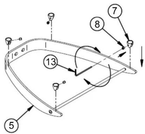
3
Fix the shelf to the wall plate.


natural_image
Technical line drawing of a mechanical bracket or frame structure (no text or symbols)8
4
Attach cover plates (parts 2 & 3) and end caps (parts 4) to the wall plate.
i.
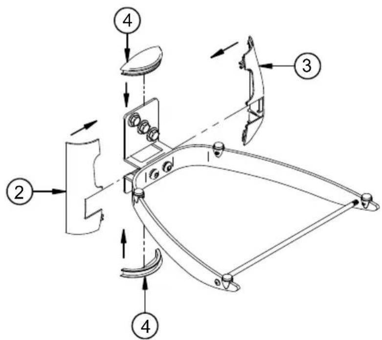
ii. Cable from top. iii. Cable from bottom.

5
Place the glass shelf onto the component shelf.

OPTIONAL ACCESSORIES
B-Tech AV Component Shelves & Cable Management.

BT7087
PRODUCT DIMENSIONS

GLASS SHELF

TEMPERED GLASS: Meets BS6206
WALL PLATE


BETTER BY DESIGN
www.btechavmounts.com
B-TECH AUDIO VIDEO MOUNTS
HEAD OFFICE
Bennett House, Long March, Daventry, Northants NN11 4NR, UK
Email: info@btechavmounts.co.uk
EUROPE
Brixtonlaan 32, Zaventem 1930,
Brussels, Belgium
Email: info@btechproav.com
NORTH AMERICA
203 Eggert Road,
Buffalo, NY 14215, USA
Email: info@btechavmounts.com
ASIA PACIFIC
Ruby Industrial Complex,
Singapore 347740
Email: info@btechavmounts.com.sg
CHINA
1503 Prosperity Millennia Plaza,
Quarry Bay, Hong Kong
Email: info@btechavmounts.com.hk
©2010 Bennett Technologies Limited. All rights reserved.
B-Tech Audio Video Mounts is a division of Bennett Technologies Limited.
B-Tech. Better By Design, System 2 & Mountlogic are registered trademarks of Bennett Technologies Limited.
All other brands and product names are trademarks of their respective owners.
Photographs are for illustrative purposes only. E&OE.
IP-BT7087-V2-OR2BX-090310-01 MADE IN CHINA


Brand : B-Tech
Model : BT7087
Category : Wall mount