TL-TP70-HDC - AV Amplifier TechLogix Networx - Free user manual and instructions
Find the device manual for free TL-TP70-HDC TechLogix Networx in PDF.

User questions about TL-TP70-HDC TechLogix Networx
0 question about this device. Answer the ones you know or ask your own.
Ask a new question about this device
Download the instructions for your AV Amplifier in PDF format for free! Find your manual TL-TP70-HDC - TechLogix Networx and take your electronic device back in hand. On this page are published all the documents necessary for the use of your device. TL-TP70-HDC by TechLogix Networx.
USER MANUAL TL-TP70-HDC TechLogix Networx
natural_image
Black TPX network device with ports and ports, no visible text or symbols on body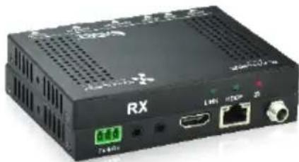
natural_image
Black RX-branded electronic device with ports and ventilation slots (no readable text or symbols beyond branding)Preface
Read this user manual carefully before using this product. Pictures shown in this manual are for reference only; the actual product may vary.
This manual is only for operation instruction only and not for any maintenance or repair.
Trademarks
Product model and logo are trademarked. Any other trademarks mentioned in this manual are acknowledged as the properties of the trademark owner. No part of this publication may be copied or reproduced without prior written consent.
FCC Statement
This equipment generates, uses and can radiate radio frequency energy and, if not installed and used in accordance with the instructions, may cause harmful interference to radio communications. It has been tested and found to comply with the limits for a Class A digital device, pursuant to part 15 of the FCC Rules. These limits are designed to provide reasonable protection against harmful interference in a commercial installation.
Operation of this equipment in a residential area is likely to cause interference, in which case the user at their own expense will be required to take whatever measures may be necessary to correct the interference.
Any changes or modifications not expressly approved by the manufacture would void the user's authority to operate the equipment.

text_image
CE FCC FEDERAL COMMUNICATIONS COMMISSION USA NOISSIPATION C-7SAFETY PRECAUTIONS
To insure proper operation, please read all instructions carefully before using the device. Save this manual for further reference.
- Unpack the equipment carefully and save the original box and packing material for possible future shipment
- Follow basic safety precautions to reduce the risk of fire, electrical shock and injury to persons.
- Do not dismantle the housing or modify the module. It may result in electrical shock or burn.
- Using supplies or parts not meeting the products' specifications may cause damage, deterioration or malfunction.
● Refer all servicing to qualified service personnel.
- To prevent fire or shock hazard, do not expose the unit to rain, moisture or install this product near water.
- Do not remove the housing of the device, as opening or removing housing may expose you to dangerous voltage or other hazards.
- Install the device in a place with adequate ventilation to avoid damage caused by overheating.
- Keep the device away from liquids.
- Spillage into the housing may result in fire, electrical shock, or equipment damage. If an object or liquid falls or spills on to the housing, unplug the device immediately.
- Do not use liquid or aerosol cleaners to clean this unit. Always unplug the power to the device before cleaning.
● Unplug the power cord when left unused for a long period of time.
- If disposing of the unit, do not burn or mix with general household waste. The device must be disposed of per local regulations for electronic recycling.
Table of Contents
1. Introduction....1
1.1 Introduction to TL-TP70-HDC....1
1.2 Features....1
1.3 Package Contents.... 1
2. Panel Description .... 2
2.1 Transmitter....2
2.2 Receiver 3
3. System Connection....5
3.1 Usage Precautions....5
3.2 System Diagram....5
3.3 Connection Procedure .... 5
3.4 Twisted Pair Cable Connection ....6
4. Specification....7
4.1 Supported Resolution....8
5. Panel Drawing....9
6. Troubleshooting & Maintenance....10
7. After-sales Service ....10
1. Introduction
1.1 Introduction to TL-TP70-HDC
The TL-TP70-HDC is an ultra-thin extender set consisting of a transmitter (TL-TP70-HDC-T) and a receiver (TL-TP70-HDC-R). Using HDBaseT technology, the set transmits an HDMI signal to the receiver up to 70m distance via a Cat5e/Cat6A cable. Featuring bi-directional IR and RS232, you can control your display or source using included accessories. With bi-directional PoE power, you only need to connect the power supply on one end.
1.2 Features
• EDID pass through
• HDCP 2.2 compliant
• 4K over Cat 5e/6 up to 40m
• 1080p over Cat 5e/6 up to 70m
• Bi-directional IR, RS232
Note: Shielded twisted pair cable with shielded connectors are recommended.
1.3 Package Contents
1 x Transmitter (TX)
1 x Receiver (RX)
4 x Mounting ears
8 x Screws
8 x Plastic cushions
1 x Power adapter (DC 24V 1.25A)
2 x RS232 cables
1 x User manual
2. Panel Description
2.1 Transmitter

text_image
TX HDCPLINK ① ② ③ RS232 IR IN IR OUT HDMI IN HDBT OUT DC 24V TX ÷ RX ④ ⑤ ⑥ ⑦ ⑧ ⑨| No. | Name | Description |
| 1 | LINK | HDBT link status indicator➢ OFF: no link➢ GREEN: link successful➢ Blinking GREEN: link abnormal |
| 2 | HDCP | HDCP compliant indicator➢ OFF: no HDMI traffic (no picture)➢ GREEN: traffic with HDCP➢ Blinking GREEN: traffic without HDCP |
| 3 | Power | OFF: No powerRED: DC power present |
| 4 | RS232 | RS232 control connector |
| 5 | IR IN | Connects to a 5V IR receiver (with carrier); signals transmitted to the remote receiver |
| 6 | IR OUT | Connects to a 5V IR emitter (with carrier); signals transmitted from the remote receiver |
| 7 | HDMI IN | Connect to an HDMI source |
| 8 | HDBT OUT | Connect to the HDBT IN socket on the receiver via a twisted pair cable; supports bi-directional PoH |
| 9 | DC 24V | Connect to the power supply (Note: power is only required on the transmitter or receiver) |
Pictures shown in this manual are only for reference.
2.2 Receiver
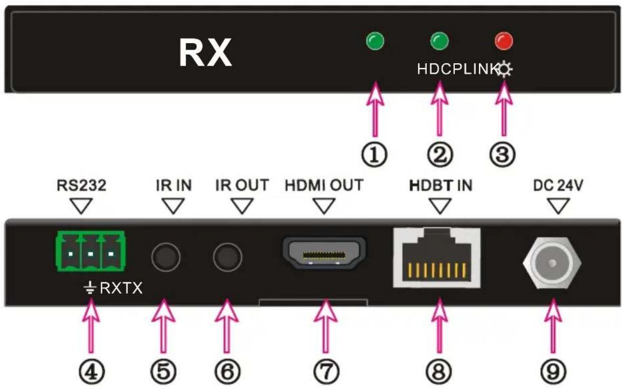
text_image
RX HDCPLINK ① ② ③ RS232 IR IN IR OUT HDMI OUT HDBT IN DC 24V ±RXTX ④ ⑤ ⑥ ⑦ ⑧ ⑨| No. | Name | Description |
| 1 | LINK | HDBT link status indicatorOFF: no linkGREEN: link successfulBlinking GREEN: link abnormal |
| 2 | HDCP | HDCP compliant indicatorOFF: no HDMI traffic (no picture)GREEN: traffic with HDCPBlinking GREEN: traffic without HDCP |
| 3 | Power | OFF: No powerRED: DC power present |
| 4 | RS232 | RS232 control connector |
| 5 | IR IN | Connects to a 5V IR receiver (with carrier); signals transmitted to the remote transmitter |
| 6 | IR OUT | Connects to a 5V IR emitter (with carrier); signals transmitted from the remote transmitter |
| 7 | HDMI OUT | Connect to an HDMI display |
| 8 | HDBT IN | Connect to the HDBT OUT socket on the transmitter via a twisted pair cable; supports bi-directional PoH |
| 9 | DC 24V | Connect to the power supply (Note: power is only required on the transmitter or receiver) |
Pictures shown in this manual are only for reference.
3. System Connection
3.1 Usage Precautions
1) System should be installed in a clean environment that has a proper temperature and humidity.
2) All of the power switches, plugs, sockets and power cords should be installed properly.
3) All devices should be connected before powering on the devices.
4) The twisted pair terminations for the devices should be a straight-thru conforming to the TIA/EIA T568B standard.
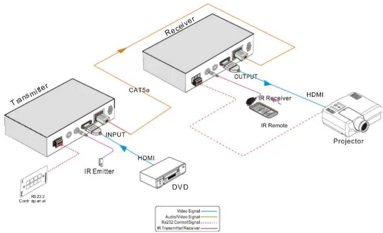
3.2 System Diagram
flowchart
graph TD
    A["Transmitter"] -->|INPUT| B["Receiver"]
    B -->|OUTPUT| C["Projector"]
    C -->|HDMI| B
    B -->|IR Emitter| A
    A -->|DVD| D["Video Signal"]
    A -->|Rs23.2 Contr dp an el| E["Audio/Video Signal"]
    B -->|IR Remote| F["IR Receiver"]
    B -->|Output| G["IR Remote"]
    style A fill:#f9f,stroke:#333
    style B fill:#ccf,stroke:#333
    style C fill:#cfc,stroke:#333
    style D fill:#fcc,stroke:#333
    style E fill:#cff,stroke:#333
    style F fill:#ffc,stroke:#333
    style G fill:#fcc,stroke:#333
3.3 Connection Procedure
Step1. Connect an HDMI source (such as a set top box) to the HDMI IN port of the transmitter with an HDMI cable.
Step2. Connect HDBT OUT port of the transmitter to HDBT IN port of the receiver using a twisted pair cable.
Step3. Connect an HDMI display to HDMI OUT port of the receiver with an HDMI cable.
Step4. If IR control is required, perform the following:
a) Connect the IR emitter to the IR OUT port on either the transmitter or
receiver.
b) Connect the IR receiver to the IR IN port on either the transmitter or receiver.
Step5. If RS232 control is required, connect the RS232 port of the devices to be controlled to the receiver or the transmitter.
Step6. Connect the DC24V power adaptor to either the transmitter or receiver. Power will be transmitter to the remote extender via the twisted pair cable.
3.4 Twisted Pair Cable Connection
The Cat5e/Cat6 terminations for HDBaseT devices should be a straight thru connection conforming to the TIA/EIAT568B standard. The TIA/EIA T568A standard is NOT recommended.
| TIA/EIA T568A | TIA/EIA T568B | |||
| Pin | Cable color | Pin | Cable color | |
| 1 | green white | 1 | orange white | |
| 2 | green | 2 | orange | |
| 3 | orange white | 3 | green white | |
| 4 | blue | 4 | blue | |
| 5 | blue white | 5 | blue white | |
| 6 | orange | 6 | green | |
| 7 | brown white | 7 | brown white | |
| 8 | brown | 8 | brown | |
| 1st Ground | 4--5 | 1st Ground | 4--5 | |
| 2nd Ground | 3--6 | 2nd Ground | 1--2 | |
| 3rd Group | 1--2 | 3rd Group | 3--6 | |
| 4th Group | 7--8 | 4th Group | 7--8 | |

text_image
12345678 12 45 78 36Note: For best operation, the twisted pair cable should be shielded and the cable connectors should be metallic. The shielded layer of cable MUST be connected to the connector's metal shell.
4. Specification
| Model Spec | Transmitter | Receiver |
| Input | ||
| Input Signal | 1 HDMI,1 IR & 1 RS232 | 1 IR, 1 RJ-45 & 1 RS232 |
| Input Connector | HDMI female, 3.5mm mini jack, 3p captive screw connector | 3.5mm mini jack, RJ45, 3p captive screw connector |
| Audio | Digital audio, transmit through HDMI audio | Digital audio, transmit through HDMI audio |
| Output | ||
| Output | 1 RJ45, 1 IR, 1 RS232 | 1 HDMI, 1 IR, 1 RS232 |
| Output Connector | RJ45, 3.5mm mini jack, 3p captive screw connector | HDMI female, 3.5mm mini jack, 3p captive screw connector |
| General | ||
| Resolution Range | 640x480@60Hz~4K×2K@30Hz | |
| Transmission Mode | HDBaseT | |
| Transmission Distance | 1080p ≤ 70m4K×2K ≤ 40m | |
| Bandwidth | 10.2Gbps | |
| HDMI Standard | Support HDMI 1.4 and HDCP 2.2 | |
| Impedance | 75Ω | |
| Temperature | 0~50°C | |
| Humidity | 10% ~ 90% | |
| Power Supply | Input: 100VAC~240VAC, 50/60HzOutput: DC 24V, 1.25A | |
| Power Consumption | 14W | |
| Dimension (W*H*D) | 115mm×16.2mm x109mm | 115mm×16.2mm x109mm |
| Net Weight | 193g | 196g |
NOTE: All nominal levels are at ±10%.
4.1 Supported Resolution
| Aspect Ratio | Resolution | Refresh Rate |
| 4Kx 2K | 4096x2160 | 30Hz |
| 3840x2160 | 24/25/30Hz | |
| 16:9 | 1920x1080 | 60Hz |
| 1600x900 | 60Hz | |
| 1366x768 | 60Hz | |
| 1280x720 | 60Hz | |
| 1024x576 | 60Hz | |
| 16:10 | 1920x1200 | 60Hz |
| 1680x1050 | 60Hz | |
| 1360x768 | 60Hz | |
| 1280x800 | 60Hz | |
| 4:3 | 1600x1200 | 60/65/70/75/85Hz |
| 1280x1024 | 60/75/85/96Hz | |
| 1024x768 | 60/70/75/85Hz | |
| 800x600 | 56/60/72/75/85Hz | |
| 640x480 | 60/72/75Hz |
5. Panel Drawing

text_image
TX HDCPLINK TL-TP70-HDC Transmitter TechLogix NFTWEX 16.2 mm RS232 IR IN IR OUT HD MI IN H DB T OUT 24V DC 109 mm 115 mm TX+ RX5-1 Transmitter
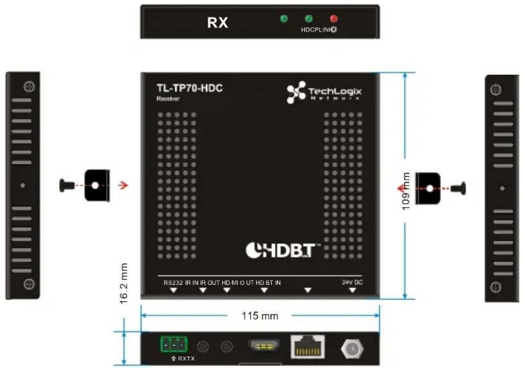
text_image
RX HDCPLINK TL-TP70-HDC Receiver® TechLogix N e t w u r a 16.2 mm RS232 IR IN IR OUT HD MI O UT HD BT IN 24V DC 109 nm 115 mm RXTX5-2 Receiver
6. Troubleshooting & Maintenance
- No image on display:
- Ensure that the display device has been set to the correct input. - Ensure that the HDMI cables used for both the source/transmitter and the receiver/display are properly connected and are working. Test the HDMI cables directly from a source to display and ensure their operation.
- Ensure that the twisted pair cable has not been damaged and that it has been terminated correctly with T568B on both ends. A temporary length of twisted pair cable can be used for testing to ensure that the devices are all compatible and working properly.
- Ensure proper grounding of the power supply.
● Known issues with HDMI 1.2 source devices:
Older compatibility (HDMI 1.2) may result in HDBaseT transmission issues. Please contact Technical Support for a solution to these issues.
● Color lose or poor picture quality:
- Ensure that the HDMI cables used for both the source and transmitter and the receiver and display are properly connected and are of good quality. Test the HDMI cables directly from a source to display and ensure their picture quality.
- Ensure proper grounding of the power supply.
- If the static becomes stronger or picture quality becomes worse when connecting the video connectors, this may be due to improper grounding.
- Check the grounding and make sure all the components are properly grounded to a common ground. Improper grounding may cause damage to the receiver.
If your problem persists after following the above troubleshooting steps, please contact your authorized reseller or TechLogix technical support.
7. After-sales Service
1) Product Limited Warranty: We warrant that our products will be free from defects in materials and workmanship for three years.
2) Warranty coverage may be voided when:
● The warranty period has expired
● The factory applied serial number has been altered or removed from the product
● There is damage, deterioration or malfunction caused by:
● Atypical wear and tear
● Use of supplies or parts not meeting the specifications
● No certificate or invoice as the proof of warranty
● Damage caused by force majeure
● Non-authorized service
3) Technical Support: When contacting TechLogix support, please have the following information available:
● Product part number
● Installation and sale date
● Detailed failure information