MCU-100S - Remote control DataVideo - Free user manual and instructions
Find the device manual for free MCU-100S DataVideo in PDF.

User questions about MCU-100S DataVideo
0 question about this device. Answer the ones you know or ask your own.
Ask a new question about this device
Download the instructions for your Remote control in PDF format for free! Find your manual MCU-100S - DataVideo and take your electronic device back in hand. On this page are published all the documents necessary for the use of your device. MCU-100S by DataVideo.
USER MANUAL MCU-100S DataVideo
natural_image
Line drawing of a multi-panel electronic device with control panels, buttons, and dials (no text or symbols)MULTI-CAMERA
CONTROL UNIT
MCU-100S
Instruction Manual
Table of Contents
FCC COMPLIANCE STATEMENT .... 3
WARNINGS AND PRECAUTIONS .... 3
WARRANTY 4
STANDARD WARRANTY 4
TWO YEAR WARRANTY 4
DISPOSAL....4
1. INTRODUCTION....5
1.1 F EATURES....5
1.2 COMPATIBLE SONY CAMERA MODELS 5
2. SYSTEM DIAGRAM....6
3. CONNECTIONS AND CONTROLS....7
3.1 I/O PANEL CONNECTORS 7
Adapter Box (AD-1S) 8
3.2 CONTROL KEYBOARD....10
Keyboard Control Guide.... 10
Seven segment display and LEDs 16
Operation Modes – LOCK and NORMAL 16
4. CAMERA SETUPS 17
4.1 HOW TO COPY SETTINGS SET BY MCU-100S FROM ONE CAMERA TO ANOTHER.... 17
4.2 H OW TO STORE / RECALL SETTINGS FROM INTERNAL MEMORY (MU-1 / MU-2 / MU-3) ... 17
4.3 HOW TO SAVE / LOAD THE CAMCORDER SETTINGS TO / FROM A PC....18
5. FIRMWARE UPDATE PROCEDURE.... 19
5.1 HOW TO UPDATE THE MCU-100S FIRMWARE 19
5.2 HOW TO UPDATE THE AD-1S FIRMWARE 19
6. DIMENSIONS 20
7. SPECIFICATIONS.... 21
SERVICE & SUPPORT 22
Disclaimer of Product & Services
The information offered in this instruction manual is intended as a guide only. At all times, Datavideo Technologies will try to give correct, complete and suitable information. However, Datavideo Technologies cannot exclude that some information in this manual, from time to time, may not be correct or may be incomplete. This manual may contain typing errors, omissions or incorrect information. Datavideo Technologies always recommend that you double check the information in this document for accuracy before making any purchase decision or using the product. Datavideo Technologies is not responsible for any omissions or errors, or for any subsequent loss or damage caused by using the information contained within this manual. Further advice on the content of this manual or on the product can be obtained by contacting your local Datavideo Office or dealer.
FCC Compliance Statement
This device complies with part 15 of the FCC rules. Operation is subject to the following two conditions:
- This device may not cause harmful interference, and
- This device must accept any interference received, including interference that may cause undesired operation.
Warnings and Precautions
- Read all of these warnings and save them for later reference.
- Follow all warnings and instructions marked on this unit.
-
Unplug this unit from the wall outlet before cleaning. Do not use liquid or aerosol cleaners. Use a damp cloth for cleaning.
-
Do not use this unit in or near water.
-
Do not place this unit on an unstable cart, stand, or table. The unit may fall, causing serious damage.
-
Slots and openings on the cabinet top, back, and bottom are provided for ventilation. To ensure safe and reliable operation of this unit, and to protect it from overheating, do not block or cover these openings. Do not place this unit on a bed, sofa, rug, or similar surface, as the ventilation openings on the bottom of the cabinet will be blocked. This unit should never be placed near or over a heat register or radiator. This unit should not be placed in a built-in installation unless proper ventilation is provided.
-
This product should only be operated from the type of power source indicated on the marking label of the AC adapter. If you are not sure of the type of power available, consult your Datavideo dealer or your local power company.
-
Do not allow anything to rest on the power cord. Do not locate this unit where the power cord will be walked on, rolled over, or otherwise stressed.
-
If an extension cord must be used with this unit, make sure that the total of the ampere ratings on the products plugged into the extension cord do not exceed the extension cord rating.
-
Make sure that the total amperes of all the units that are plugged into a single wall outlet do not exceed 15 amperes.
-
Never push objects of any kind into this unit through the cabinet ventilation slots, as they may touch dangerous voltage points or short out parts that could result in risk of fire or electric shock. Never spill liquid of any kind onto or into this unit.
-
Except as specifically explained elsewhere in this manual, do not attempt to service this product yourself. Opening or removing covers that are marked "Do Not Remove" may expose you to dangerous voltage points or other risks, and will void your warranty. Refer all service issues to qualified service personnel.
-
Unplug this product from the wall outlet and refer to qualified service personnel under the following conditions:
a. When the power cord is damaged or frayed;
b. When liquid has spilled into the unit;
c. When the product has been exposed to rain or water;
d. When the product does not operate normally under normal operating conditions. Adjust only those controls that are covered by the operating instructions in this manual; improper adjustment of other controls may result in damage to the unit and may often require extensive work by a qualified technician to restore the unit to normal operation;
e. When the product has been dropped or the cabinet has been damaged;
f. When the product exhibits a distinct change in performance, indicating a need for service.

Warranty
Standard Warranty
- Datavideo equipment is guaranteed against any manufacturing defects for one year from the date of purchase.
- The original purchase invoice or other documentary evidence should be supplied at the time of any request for repair under warranty.
- Damage caused by accident, misuse, unauthorized repairs, sand, grit or water is not covered by this warranty.
- All mail or transportation costs including insurance are at the expense of the owner.
- All other claims of any nature are not covered.
• Cables & batteries are not covered under warranty. - Warranty only valid within the country or region of purchase.
- Your statutory rights are not affected.
Two Year Warranty
- All Datavideo products purchased after 01-Oct.-2008 qualify for a free one year extension to the standard Warranty, providing the product is registered with Datavideo within 30 days of purchase. For information on how to register please visit www.datavideo.com or contact your local Datavideo office or authorized Distributors.

- Certain parts with limited lifetime expectancy such as LCD Panels, DVD Drives, Hard Drives are only covered for the first 10,000 hours, or 1 year (whichever comes first).
Any second year warranty claims must be made to your local Datavideo office or one of its authorized Distributors before the extended warranty expires.
Disposal

natural_image
Symbol of a trash bin crossed with diagonal lines, no text or labels presentFor EU Customers only - WEEE Marking
This symbol on the product or on its packaging indicates that this product must not be disposed of with your other household waste. Instead, it is your responsibility to dispose of your waste equipment by handing it over to a designated collection point for the recycling of waste electrical and electronic equipment. The separate collection and recycling of your waste equipment at the time of disposal will help to conserve natural resources and ensure that it is
recycled in a manner that protects human health and the environment. For more information about where you can drop off your waste equipment for recycling, please contact your local city office, your household waste disposal service or the shop where you purchased the product.

CE Marking is the symbol as shown on the left of this page. The letters "CE" are the abbreviation of French phrase "Conformité Européenne" which literally means "European Conformity". The term initially used was "EC Mark" and it was officially replaced by "CE Marking" in the Directive 93/68/EEC in 1993. "CE Marking" is now used in all EU official documents.
1. Introduction
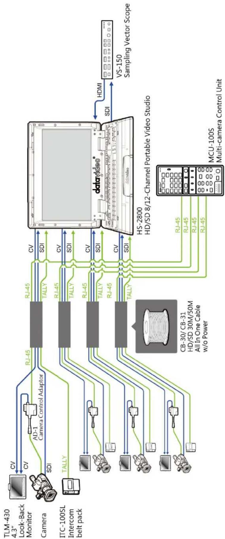
The MCU-100S is a multiple camera controller designed for controlling SONY studio or portable camcorders. Its useful and user-friendly design allows you to connect a maximum of 4 SONY camcorders through the Ethernet cables and an adapter box. Major functions of several SONY camcorders can be easily operated and controlled using the MCU-100S at up to 300m away from the controller unit.
The Datavideo MCU-100S Controller is capable of remotely configuring SONY Camcorders from an OB Van. The MCU-100S can connect up to four SONY cameras allowing settings from one camera to be quickly aligned with other cameras. With features similar to the SONY Extension Control Unit, the MCU-100S reduces cost in manpower and equipment and saves setup time and disk space for you.
To get more value out of this equipment please take a few minutes to read through this manual. This will help familiarizing yourself with all the aspects of the MCU-100S control unit.
That's Datavideo; sharing the value!
1.1 Features
- Four RJ-45 Ethernet ports allow remote setup of up to four SONY cameras.
- RJ-45 cabling allows unit to be placed up to 300m away from the camera(s).
• Control of Record and Playback functions.
• Control of Camera User memory functions.
• Control of Camera OSD Menu Navigation.
• Control of Shutter speed and degree functions.
• Control of Iris adjustment.
• Control of AWB & ABB functions.
• Control of White Balance A, B and Preset functions.
• Control of Camera Knee & Bars functions.
• Control of Camera Gain adjustment. - RGB Black Level / R & B gain and Master Pedestal controls.
1.2 Compatible SONY Camera Models\*
• PMW - F5 / EX3 / EX350 / 300K2 / 350K / 320 / 400
• PDW - 510 / 510P / F55
• PMW - F3 / 300 / 350
• HDW - 730S / 750P / 790P / F900R
*Note: Please see the product page on our official website for the updated list.
2. System Diagram
flowchart
graph LR
    subgraph Camera
        A["Look-Back Monitor"] -->|CV| B["AD-1 Camera Control Adaptor"]
        C["TLM-430 4.3""] -->|CV| B
        D["Camera"] -->|SDI| B
        E["ITC-100SL Intercom belt pack"] -->|TALLY| B
    end

    subgraph Video
        F["DSI"] --> G["TALLY"]
        H["SDI"] --> I["TALLY"]
        J["SDI"] --> K["TALLY"]
        L["SDI"] --> M["TALLY"]
        N["SDI"] --> O["TALLY"]
    end

    B --> P["RJ-45"]
    B --> Q["TALLY"]
    I --> P
    I --> Q
    K --> P
    K --> Q
    M --> P
    M --> Q
    P --> R["DSI"]
    Q --> R
    R --> S["HDMI"]
    S --> T["VS-150 Sampling Vector Scope"]

    subgraph Computer
        U["DSI"] --> V["DSI"]
        W["RTS"] --> X["RTS"]
        Y["MTS"] --> Z["MTS"]
        AA["PC"] --> AB["PC"]
        AC["AC"] --> AD["AC"]
        AE["AE"] --> AF["AF"]
        AG["AG"] --> AH["AG"]
        AI["AI"] --> AJ["AI"]
        AK["AK"] --> AL["AL"]
        AM["AM"] --> AN["AN"]
        AO["AO"] --> AP["AP"]
        AQ["AQ"] --> AR["AR"]
        AS["AS"] --> AT["AT"]
        AU["AU"] --> AV["AV"]
        AW["AW"] --> AX["AX"]
        AY["AY"] --> AZ["AZ"]
        BA["B"] --> BB["B"]
        BC["B"] --> BD["B"]
        BE["B"] --> BF["B"]
        BG["B"] --> BH["B"]
        BI["B"] --> BJ["B"]
        BK["B"] --> BL["B"]
        BM["B"] --> BN["B"]
        BO["B"] --> BP["B"]
        BQ["B"] --> BR["B"]
        BS["B"] --> BT["B"]
        BU["B"] --> BV["B"]
        BW["B"] --> BX["B"]
        BY["B"] --> BZ["B"]
    end

    subgraph Computer
        Y["HDMI"] --> Z["HDMI"]
    end

    subgraph Computer
        AA["HDMI"] --> AB["HDMI"]
    end

    subgraph Computer
        AC["HDMI"] --> AD["HDMI"]
    end

    subgraph Computer
        AE["HDMI"] --> AF["HDMI"]
    end

    subgraph Computer
        AZ["HDMI"] --> BA["HDMI"]
    end

    subgraph Computer
        BB["HDMI"] --> BC["HDMI"]
    end

    subgraph Computer
        AD["HDMI"] --> AE
    end

    subgraph Computer
        AF["HDMI"] --> BB
    end

    subgraph Computer
        CA["HDMI"] --> AZ
    end

    subgraph Computer
        DB["HDMI"] --> BC
    end

    subgraph Computer
        DC["HDMI"] --> BE
    end

    subgraph Computer
        DD["HDMI"] --> BE
    end

    subgraph Computer
        BE["HDMI"] --> BF
    end

    subgraph Computer
        BG["HDMI"] --> BE
    end

    subgraph Computer
        BH["HDMI"] --> BE
    end

    subgraph Computer
        BI["HDMI"] --> BE
    end

    subgraph Computer
        BJ["HDMI"] --> BE
    end

    subgraph Computer
        BK["HDMI"] --> BE
    end

    subgraph Computer
        BL["HDMI"] --> BE
    end

    subgraph Computer
        BN["HDMI"] --> BE
    end

    subgraph Computer
        BO["HDMI"] --> BE
    end

    subgraph Computer
        BP["HDMI"] --> BE
    end

    subgraph Computer
        BOH["HDMI"] --> BE
    end

    subgraph Computer
        BPH["HDMI"] --> BE
    end

    subgraph Computer
        BPJ["HDMI"] --> BE
    end

    subgraph Computer
        BPK["HDMI"] --> BE
    end

    subgraph Computer
        BPL["HDMI"] --> BE
    end

    subgraph Computer
        BPM["HDMI"] --> BE
    end

    subgraph Computer
        BPN["HDMI"] --> BE
    end

    subgraph Computer
        BPO["HDMI"] --> BE
    end

    subgraph Computer
        BPP["HDMI"] --> BE
    end

    subgraph Computer
        BPQ["HDMI"] --> BE
    end

    subgraph Computer
        BPR["HDMI"] --> BE
    end

    subgraph Computer
        BPS["HDMI"] --> BE
    end

    subgraph Computer
        BPT["HDMI"] --> BE
    end

    subgraph Computer
        BPU["HDMI"] --> BE
    end

    subgraph Computer
        BPV["HDMI"] --> BE
    end

    subgraph Computer
        BPW["HDMI"] --> BE
    end

    subgraph Computer
        BPX["HDMI"] --> BE
    end

    subgraph Computer
        BPY["HDMI"] --> BE
    end

    subgraph Computer
        BPZ["HDMI"] --> BE
    end

    subgraph Computer
        BPWY["HDMI"] --> BE
    end

    subgraph Computer
        BPXW["HDMI"] --> BE
    end

    subgraph Computer
        BPXZ["HDMI"] --> BE
    end

    subgraph Computer
        BPYX["HDMI"] --> BE
    end

    subgraph Computer
        BPYZH["HDMI"] --> BE
    end

    subgraph Computer
        BPZXH["HDMI"] --> BE
    end

    subgraph Computer
        BPZXY["HDMI"] --> BE
    end

    subgraph Computer
        BPZXZ["HDMI"] --> BE
    end

    subgraph Computer
        BPZXYX["HDMI"] --> BE
    end

    subgraph Computer
        BPZXYXZ["HDMI"] --> BE
    end

    subgraph Computer
        BPZXYXH["GHD/SD 30M/50M All In One Cable w/o Power"]
    end

    subgraph Computer
        MPa[X, SDI, RGB, etc., Multi-camera Control Unit, MCU-100S, DSI, HD/SD 8/12-Channel Portable Video Studio, VS-150 Sampling Vector Scope, HDMI, SDI, HDMI, HDMI, HDMI, HDMI, HDMI, HDMI, HDMI, HDMI, HDMI, HDMI, HDMI, HDMI, HDMI, HDMI, HDMI, HDMI, HDMI, HDMI, HDMI, HDMI, HDMI, HDMI, HDMI, HDMI, HDMI, HDMI, HDMI, HDMI, HDMI, HDMI, HDMI, HDMI, HDMI, HDMI, HDMI, HDMI, HDMI, HDMI, HDMI, HDMI, HDMI, HDMI, HDMI, HDMI, HDMI, HDMI, HDMI, HDMI, HDMI, HDMI, DDR, DDR, DDR, DDR, DDR, DDR, DDR, DDR, DDR, DDR, DDR, DDR, DDR, DDR, DDR, DDR, DDR, DDR, DDR, DDR, DDR, DDR, DDR, DDR, DDR, DDR, DDR, DDR, DDR, DDR, DDR, DDR, DDR, DDR, DDR, DDR, DDR, DDR, DDR, DDR, DDR, DDR, DDR, DDR, DDR, DDR, DDR, DDR, DDR, DDR,<nl>
3. Connections and Controls
3.1 I/O Panel Connectors
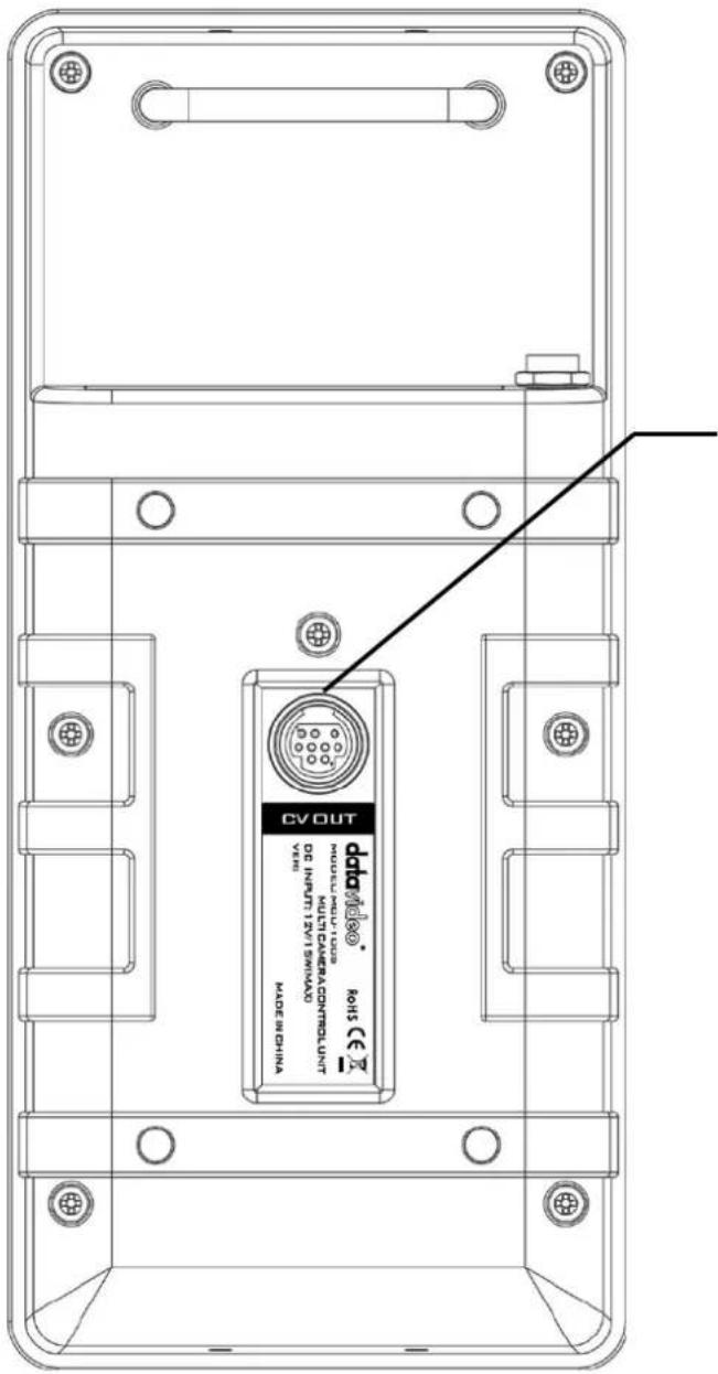
This 9 pin Mini Din port can be used for confidence and composition monitoring and in some cases to view the camera's own LCD/OSD menus.
To use this feature, please connect the Mini-Din end of the CB-40 cable (1 Mini Din to 4 CV Out) to this port.
CB-40 is an optional accessory.
natural_image
Four identical abstract geometric shapes arranged horizontally (no text or symbols)
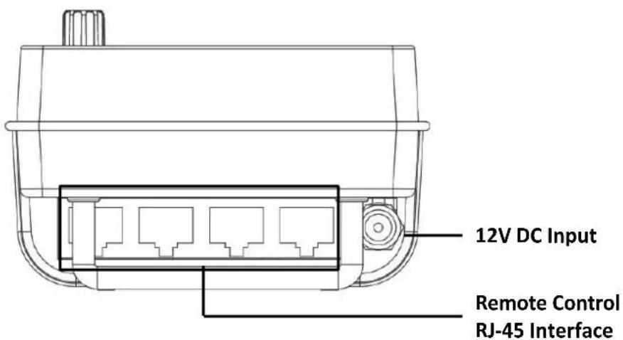
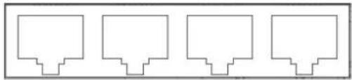
Remote Control
Four RJ-45 ports allow remote control of up to four SONY cameras.
12V DC Input
Connects the supplied 12V PSU to this socket. The connection can be secured by screwing the outer fastening ring of the DC In plug to the socket.
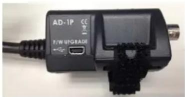
Adapter Box (AD-1S)
The adapter box acts as an interface between the MCU-100S and SONY cameras or camcorders. One side of the box connects to the MCU-100S via an Ethernet cable and the other side connects to SONY cameras or camcorders via a SONY CAM/BS cable. Users are allowed to use an Ethernet cable that runs 300 meters to connect the MCU-100S to this adapter box which in turn connects a SONY camera.
The CV output connects the monitor which will display the camcorder settings.

This unit allows you to operate the functions of the camera up to 300m away with the MCU-100S unit.
The AD-1S adaptor connects the MCU-100S via RJ-45 cabling to the chosen Sony camera. This adaptor changes the Ethernet connection to a Sony CAM/BS cable run with a multi-pin connector.
NOTE: Before using the MCU-100S to control the connected cameras, you have to enable the camera's remote control function. For instructions on how you can enable the remote control function, please see the corresponding user manual.
NOTE: Be very careful with the Sony CAM/BS cable connector which plugs into the remote socket of the Sony camera. This connector only slides into the camera's remote socket when the notches and pins are matched up correctly. Do not twist or force this connection as damage to the camera or connector pins may happen.
NOTE: With the AD-1S connected, the menu and other functions of the Sony camera may be limited to remote control only. To regain manual control of the menu functions on the camera first disconnect the AD-1S.
The AD-1S also features a BNC type Composite (CV) output which can be taken to an SD monitor on or near the camera. This Composite output can be used for confidence and composition monitoring and in some cases to view the camera's own LCD/OSD menus too. Please note this feature is camera model and firmware dependant.
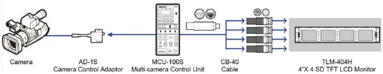
flowchart
graph LR
    A["Camera"] --> B["AD-1S Camera Control Adaptor"]
    B --> C["MCU-100S Multi-camera Control Unit"]
    C --> D["CB-40 Cable"]
    D --> E["TLM-404H 4"X 4 SD TFT LCD Monitor"]
    C --> F["Image Panel"]
    C --> G["Image Panel"]
    C --> H["Image Panel"]
Each AD-1S adaptor has a built in Velcro strap so that the unit can be quickly mounted in a convenient location on or near the camera.
A micro USB 2.0 port is provided for transfer of firmware updates to the unit. See Firmware Update section for more details.
3.2 Control Keyboard
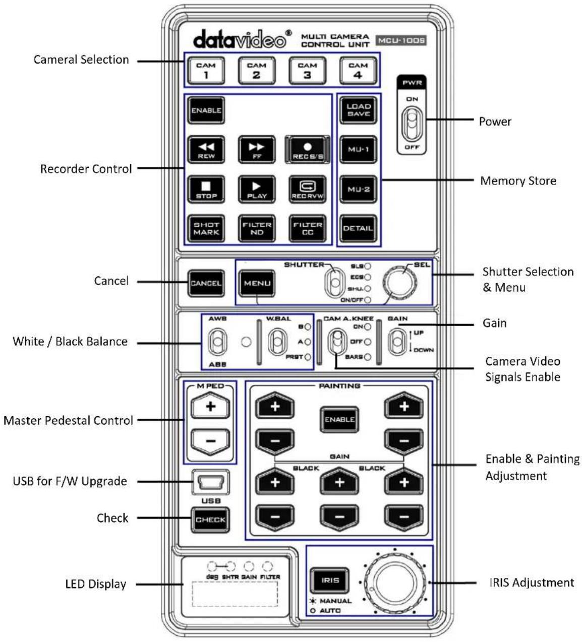
Keyboard Control Guide
Power switch
Use this switch to power the MCU-100S On or Off.

Camera selection
Select the button for the camera that you wish to control.


MCU-100S Memory stores
Using the LOAD SAVE button it is possible to transfer the current setting from one camera to another.
MU-1, MU-2 can be used to store settings within the MCU-100S.
DETAIL
In Remote Control mode, press and light this button to enable the Detail function.
Note: The LOAD SAVE / MU1 / MU2 functions are not applicable to SONY EX3 & PMW-300EX cameras.


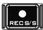
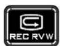
Recorder / Playback functions
ENABLE when selected activates the recorder / playback functions of the chosen camera. This includes rewind [REW], fast forward [FF], record start/stop [REC S/S], stop, play and record check [REC RVW].
REC RVW makes it possible to check what has just been recorded (2 seconds REC review) by pressing this button during REC pause.
With a DVCPRO HD camera recorder, the tape is cued to provide continuity from one shot to the next when this button is pressed while playback is paused.
Note: The REW and FF functions may be modified during the firmware upgrade process.


SHORT MARK
Press this button during recording or playback to record shot mark 1.
ND (ND filter) select switch and indicator
Use this switch to select the ND filter. Press the switch upward to change the ND filter in order and downward to change the ND filter in the reverse order. The ND indicator displays the currently selected ND filter. This switch is disabled for a camera not equipped with an ND filter servo system or a camera without ND filters.
Note: The FILTER ND function is not applicable to SONY EX3 & PMW-300EX cameras.
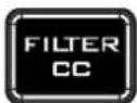
CC (color temperature conversion filter) select switch and indicator
Use this switch to select the CC filter. Press the switch upward to change the CC filter in order and downward
to change the CC filter in the reverse order. The CC indicator displays the currently selected CC filter. This switch is disabled for a camera not equipped with a CC filter servo system or a camera without CC filters.
Note: The FILTER CC function is not applicable to SONY EX3 & PMW-300EX cameras.

CANCEL
In Camera Menu mode, press this button to cancel the set value.

Menu
When this function is enabled, the button is back lit orange and the OSD menu is shown on the LCD panel/view finder of the camera. This OSD menu may also be shown on the AD-1S's composite output (if supported).
Some camera models also allow this OSD menu to be displayed on the SDI or HDMI output of the chosen camera. Refer to your cameras manual for more details on its OSD Menu outputs and change settings where necessary.
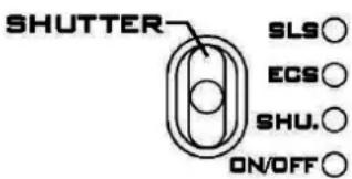
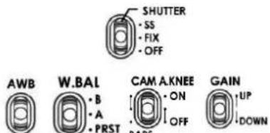
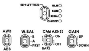
SHUTTER
In shutter operation mode, Moving this switch to enable the Shutter function. The current shutter speed is displayed on the adjustment value indicator and the shutter speed can be adjusted with the adjustment knob (rotary encoder). In Camera Menu mode, moving the switch to enable the character display function on the camera.
ON/OFF
The LED displays the status of shutter operation on/off.
ECS (Extended Clear Scan)
In shutter operation mode, moving the switch to enable the ECS function.
SLS (Slow Shutter)
In shutter operation mode, moving the switch to enable the SLS function.
Note: The SLS function may be modified during the firmware upgrade process.

AWB
ABB

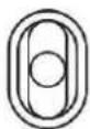
SEL - Select dial
The select dial is used for two functions, to navigate the menus or to control the shutter speed.
When the MENU button is active and back lit orange. The select dial is turned to navigate through the camera's menu options. Pressing in the same dial, like a button, confirms the current selection or value shown.
When the MENU button is NOT active and back lit green. The select dial can be turned to adjust the SHUTTER speed of the camera.
AWB / ABB switch with LED
This switch is used to trigger Auto White Balance (AWB) or Auto Black Balance (ABB) adjustment.
AWB: White balance is adjusted automatically. When the W.BAL switch is set to A or B at this time, the value to which the balance was adjusted will be stored in memory A or memory B.
ABB: Black balance is adjusted automatically. This value will be stored in a dedicated ABB memory.
LED ON: Auto white balance / auto black balance in progress.
LED OFF: Auto white balance / auto black balance completed.
LED stops blinking and goes off: Auto white balance / auto black balance error.
Note: The AWB / ABB functions may be modified during the firmware upgrade process.
W.BAL
B○

A○
PRST
W.BAL switch
This switch is used to recall the preset or stored values of white balance in the camera.
A or B: This will apply the value stored in the white balance A or B memory in the camera recorder. When the AWB / ABB switch is set to the AWB position, the white balance is automatically adjusted and the value adjusted is stored in the selected memory A or B.
PRST
This will apply the preset value of the white balance stored in the camera recorder.
CAM A.KNEE

CAM A.KNEE switch
To select the video signals to be output from the camera.
BARS
Camera generated colour bar signals are output.
CAM. AUTO KNEE OFF
The images shot by camera are output. The AUTO KNEE circuit does not work. MANUAL KNEE is set as the camera recorder's initial setting.
CAM. AUTO KNEE ON
The images shot by the camera are output. The AUTO KNEE circuit works.
NOTE: AUTO KNEE circuit will not be effective if DRS (Dynamic Range Stretch) function is enabled. It is also possible allocate the MANUAL KNEE and DRS functions via the menu settings on the camera.
GAIN

GAIN switch
Allows selection of the video amplifier's gain depending on the lighting conditions that are present in the camera's location.
Moving the switch upwards increases the gain in dB steps.
Moving the switch downwards decreases the gain in dB steps.
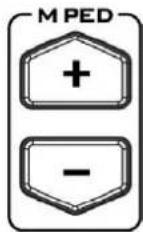
Master Pedestal Control
These buttons are used to adjust the level of the Master Pedestal.
flowchart
graph TD
    A["PAINTING"] --> B["ENABLE"]
    B --> C["+"]
    B --> D["+"]
    B --> E["-"]
    B --> F["+"]
    G["GAIN"] --> H["BLACK"]
    G --> I["BLACK"]
    G --> J["+"]
    G --> K["-"]
    G --> L["+"]
    G --> M["-"]
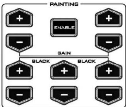
Enable & Painting Adjustment buttons
Press the ENABLE button in the Painting area of the MCU-100S before choosing to adjust either the level of the Red and Blue Gain or the RGB Pedestal values.

Mini USB 2.0 port
This port is used for firmware updates or to save/transfer MCU-100S settings to computer.
See Firmware Update section for firmware upgrade details.

CHECK / LOCK
GAIN value, SHUTTER speed, FILTER position, IRIS, Master Pedestal, R/B Gain and RGB pedestal values are shown on the display below in this order each time the CHECK button is pressed.
If the CHECK button is pressed and held down for over two seconds the MCU-100S unit will switch in to LOCK mode.
Note: The Check function may be modified during the firmware upgrade process.

LED display
The IRIS value, Shutter degree, speed, Gain and Filter positions can be displayed here by using the CHECK button.
*The M. PED, PAINTING GAIN R/B and BLACK R/G/B values can also be displayed sequentially here. See CHECK button also.
When in LOCK mode this display will show Lock.
Note: The LED display functions may be modified during the firmware upgrade process.
EXT

EXT LED
This LED will be ON when a lens extender is detected on the chosen camera.
Note: The EXT LED function may be modified during the firmware upgrade process.

IRIS button
To enable or disable Auto Iris.
The button is back lit orange when Auto Iris is enabled.
natural_image
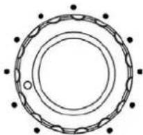
Circular mechanical component diagram with concentric rings and mounting holes (no text or symbols)IRIS control
Used to adjust the Iris value. See IRIS and CHECK buttons also.
Seven segment display and LEDs
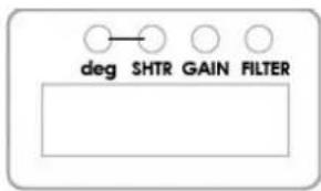
| Deg Indicator | To indicate the displayed format of SHUTTER value.ON: Shutter angle is displayed.OFF: Shutter speed is displayed. |
| SHTR Indicator | This lights up when LED display shows SHUTTER (speed) value. |
| GAIN Indicator | This lights up when LED display shows GAIN value (in dB). |
| FILTER Indicator | This lights up when LED display shows ND FILTER mode (F1~F5). |
Operation Modes - LOCK and NORMAL
There are two modes of operation on the MCU-100S.
NORMAL: This is always active when the unit is first turned on. Under this mode all functions are available. Buttons not back lit indicate functions that are currently not in use. The user may activate these functions via an associated ENABLE button.
LOCK: This mode is activated by pressing and holding down the CHECK button for two seconds. When in LOCK mode all functions are unavailable except for the 4 Camera selection buttons and the CHECK function. This is to prevent unauthorized or unintended operation during a LIVE production. The seven segment LED display will also show Lock.
Iris controls can be quickly accessed in LOCK mode by pressing down on the IRIS Dial once; press the dial again to return to full lock mode. When the Iris function is accessed in this way, if the MCU-100S unit is left idle for 3 seconds or more then the unit will automatically return to full LOCK mode.
The LOCK mode can be deactivated by pressing and holding down the CHECK button for two seconds.
4. Camera Setups
4.1 How to copy settings set by MCU-100S from one camera to another
When MCU-100S is used to control more than one camera, it is possible to copy the settings set by the unit on one camera to another via the Memory Stores functions of the unit.
Follow the following procedure to copy the settings set by the unit on camera to another.
- Select the camera from which you want to copy the settings via the CAM 1 to CAM 4 buttons.
- Press the LOAD SAVE button to start the copy process. The LOAD SAVE button will be back lit orange and blinking.
- Whilst the LOAD SAVE button is back lit orange and blinking select the camera to which you want to copy the settings via the CAM 1 to CAM 4 buttons.
- When the LOAD SAVE button is back lit green the copy process is then completed.
Note: This process does not work if either the selected source or destination camera is not connected or is not powered on.
4.2 How to store / recall settings from internal memory (MU-1 / MU-2 / MU-3)
The MCU-100S has dedicated internal memory to store the settings set by the unit on four cameras. This internal memory can be accessed using the Memory Store functions.
Internally, the unit has three memory blocks indicated by the Memory Stores MU-1, MU-2 and MU-3. Each of these blocks is divided into four segments, one segment for each camera. These are used to store the settings for each camera accordingly.
Use this procedure to store the settings on a camera to the MCU-100S unit's internal memory.
- Select the camera from which you want to copy the settings via the CAM 1 to CAM 4 buttons.
- Press the LOAD SAVE button to start the copy process. The LOAD SAVE and the selected camera button will be back lit orange and blinking.
- Whilst these buttons are back lit orange and blinking select the memory block, MU-1, MU-2 or MU-3 button, to which you want to copy the settings.
- When the MU-1, MU-2 or MU-3 button is back lit green and the copy process is then completed.
Use this procedure to recall a previously saved setting on the MU-1, MU-2 or MU-3 button to a camera.
- Select the camera to which you want to copy the stored settings via the CAM 1 to CAM 4 buttons.
- Select the memory block from which you want to copy the settings via the MU-1, MU-2 or MU-3 button.
- Press the LOAD SAVE button to start the copy process. The LOAD SAVE and the selected camera button will be back lit orange and blinking.
- These buttons will be back lit green when copy process is completed.
4.3 How to save / load the camcorder settings to / from a PC
It is possible to save the current settings on all four cameras from MCU-100S to a PC for later use. Also any previously saved MCU-100S settings stored on a PC can also be loaded back to the MCU-100S unit. This can be handy if multiple users have access to the equipment and you need a quick way to get back to your preferred settings.
Use the following procedure to save the current camera settings set by the MCU-100S unit to a PC.
- Power off the MCU-100S unit.
- Connect the MCU-100S unit to PC using a USB cable via the USB 2.0 (Mini B) interface.
- Set the five switches ABB on the MCU-100S unit to their middle position.
- Press and hold in both the CAM 1 & MU-1 buttons at same time and then power on the MCU-100S unit.
- The seven segments LED Display will show "cU--", and the PC will detect the MCU-100S unit as an external storage device named "MCU-100S MUx".
- Open the "MCU-100S_MUx" folder on the PC and copy "mu_param.bin" file to desired PC hard drive location.
- Once complete unplug the USB cable and reboot the MCU-100S unit.
To load previously saved settings on a PC to MCU-100S, repeat steps 1\~5 of the above procedure and then continue with the following steps.
-
Open the "MCU-100S MUx" file folder on PC and delete the "mu param.bin" file.
-
Copy the previously saved "mu_param.bin" file from the PC hard drive location to the "MCU-100S MUX" folder.
Note: Do not worry if the previously saved xxxxxxxxx.bin file has been renamed on the PC. The MCU-100S unit will automatically amend the file name back to "mu_param.bin" after a reboot.
- Once the copy process is complete unplug the USB cable and reboot the MCU-100S unit.
5. Firmware Update Procedure
From time to time Datavideo may release new firmware to either add new features or to fix reported bugs in the current MCU-100S firmware. Customers can update the firmware themselves if they wish or they can contact their local dealer or reseller for assistance should they prefer this method.
This page describes the firmware update process and it should take approximately 20 minutes total time to complete. Once started the update process should not be interrupted in any way as this could result in a non-responsive unit.
As well as a working MCU-100S you will need:
The latest firmware update for the AD-1S units and the MCU-100S.
USB 2.0 cable (USB A type-to-Micro USB).
A Windows computer (Vista / 7) with USB 2.0 port.
Note: It is best to update the firmware of the AD-1S unit(s) at the same time as the MCU-100S.
5.1 How to update the MCU-100S firmware
- Turn off the MCU-100S power.
- Connect the MCU-100S to PC via a USB cable.
- Set the five switches ABB FAST BARS on the MCU-100S to their middle position.

- Move ABB switch up towards (AWB) and at the same time also press the shutter select button. Hold both in place.
- Turn on the MCU-100S power.
- MCU-100S LED display will show "L-x.x", and the PC will find MCU-100S by USB 2.0.
- Open "MCU-100S_U1" disk on PC.
- Delete the bootcode.bin file in "MCU-100S_U1" disk.
- Copy new xxxxxxxxx.bin file to the "MCU-100S_U1" disk. Do not worry about the new file name; the MCU-100S will amend the file name automatically after reboot.
- Reboot MCU-100S.
5.2 How to update the AD-1S firmware
- Connect AD-1S to the PC via a USB cable (USB A Type – Micro USB)
- Power on PC
- Copy the firmware binary file to AD-1S from the PC.
Note:
1: It is best to update the firmware of the AD-1S unit(s) at the same time as the MCU-100S.
2: Please use win7 or earlier operating system.
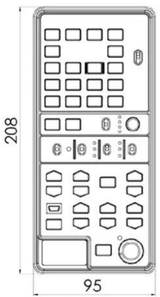
6. Dimensions
MCU-100S
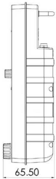
AD-1S
All measurements in millimeters (mm)
7. Specifications
| Model Name | MCU-100S |
| Product Name | Multi-Camera Control Unit |
| Input / Output Interface | RJ45 x 4CV x 1 |
| Camera Adapter | AD-1S |
| Remote Control Interface | Ethernet |
| Number of Cameras Controlled 4 | |
| Maximum Transmission Distance | Up to 300m (CAT-5 or CAT6) |
| Supported Functions | Record and PlaybackCamera User Memory FunctionsCamera OSD Menu NavigationShutter Speed and Degree FunctionsIris AdjustmentAWB & ABB FunctionsWhite Balance A / B and Preset FunctionsCamera Knee & Bars FunctionsCamera Gain AdjustmentRGB Black Level / R&B Gain and Master Pedestal Controls |
| Compatible Camera Models | PMW - F5 / EX3 / EX350 / 300K2 / 350K / 320 / 400PDW - 510 / 510P / F55PMW - F3 / 300 / 350HDW - 730S / 750P / 790P / F900R |
| Power Supply | DC 12V / 0.5A |
| Power Consumption 15 W | |
| Dimensions | 95mm (W) x 208mm (H) x 65.5mm (D) |
| Weight 350g |
Service & Support
It is our goal to make owning and using Datavideo products a satisfying experience. Our support staff is available to assist you to set up and operate your system. Contact your local office for specific support requests. Plus, please visit www.datavideo.com to access our FAQ section.
Datavideo Taiwan
Datavideo Technologies Co. Ltd 10F. No. 176, Jian 1st Rd., Chung Ho District, New Taipei City 235, Taiwan, R.O.C. Tel: +886-2-8227-2888 Fax: +886-2-8227-2777 E-mail: service@datavideo.com.tw
Datavideo Europe
Datavideo Technologies Europe BV Floridadreef 106 3565 AM Utrecht, The Netherlands Tel: +31-30-261-96-56 Fax: +31-30-261-96-57 E-mail: info@datavideo.nl
Datavideo United Kingdom
Datavideo UK Limited Units1 & 2 Waterside Business Park Hadfield, Glossop, Derbyshire SK13 1BE, UK Tel: +44-1457 851 000 Fax: +44-1457 850 964 E-mail:sales@datavideo.co.uk
Datavideo USA
Datavideo Corporation 7048 Elmer Avenue. Whittier, CA 90602, U.S.A. Tel:+1-562-696 2324 Fax:+1-562-698 6930 E-mail:sales@datavideo.us
Datavideo China
Datavideo Technologies China Co 101, NO.618, LiuYing Rd, Zhabei District, Shanghai, China Tel: +86 21-5603 6599 Fax: +86 21-5603 6770 E-mail: service@datavideo.cn
Datavideo Singapore
Datavideo Technologies (S) PTE Ltd No. 178 Paya Lebar Road #06-03 Singapore 409030
Datavideo Hong Kong
Datavideo Hong Kong Ltd G/F.,26 Cross Lane Wanchai, Hong Kong Tel: +852-2833-1981 Fax: +852-2833-9916 E-mail:info@datavideo.com.hk
Datavideo France
Datavideo France s.a.r.l Cité Descartes 1, rue Albert Einstein Champs sur Marne 774477-Marne la Vallée cedex 2 Tel: +33-1-60370246 E-mail: info@datavideo.fr
Tel:+65-6749 6866 Fax:+65-6749 3266 E-mail:sales@datavideo.sg
Datavideo India
Datavideo Technologies India Pvt Ltd A-132, Sec-63, Noida-201307, Uttar Pradesh (UP), India. Tel: +91-0120-2427337 Fax: +91-0120-2427338 E-mail: sales@datavideo.in

Please refer to our website for update the latest version manual. www.datavideo.com/Camera+Control/MCU-100S
datavideo
www.datavideo.com