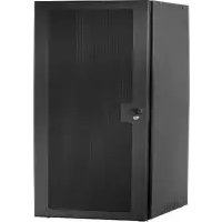
NS1D12F - Unspecified Chief - Free user manual and instructions
Find the device manual for free NS1D12F Chief in PDF.


| Product Type | Perforated Rack Door |
| Model | NS1D12F |
| Brand | Chief |
| Compatible Rack | S1 Series Racks |
| Material | Perforated Steel |
| Color | Black (assumed standard) |
| Mounting | Front mount with spring handles and door supports |
| Door Catch | Included (part B) |
| Hardware Included | Top and bottom door supports, screws, lock nuts, grounding wire |
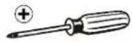
| Tools Required | 7/16" wrench, Phillips screwdriver |
| Installation Orientation | Handle on left or right (requires repositioning grounding wire) |
| Grounding | Required; uses 12 AWG green/yellow wire (not included) |
| Safety | WARNING: Improper wiring can cause death or injury; grounding must be installed by qualified personnel |
| Maintenance | Periodic check of hardware tightness; clean with mild detergent |
| Repairability | Individual parts available (door, door catch, supports) |
| Warranty | Refer to Milestone AV Technologies warranty (implied) |
| Manual Languages | English (EN) provided |
Frequently Asked Questions - NS1D12F Chief
User questions about NS1D12F Chief
0 question about this device. Answer the ones you know or ask your own.
Ask a new question about this device
Download the instructions for your Unspecified in PDF format for free! Find your manual NS1D12F - Chief and take your electronic device back in hand. On this page are published all the documents necessary for the use of your device. NS1D12F by Chief.
USER MANUAL NS1D12F Chief
INSTALLATION INSTRUCTIONS
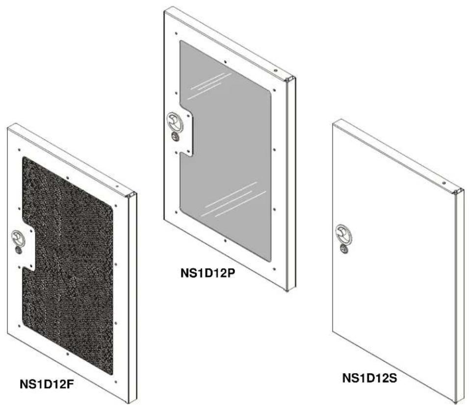
S1 Racks Doors
DISCLAIMER
Milestone AV Technologies and its affiliated corporations and subsidiaries (collectively "Milestone"), intend to make this manual accurate and complete. However, Milestone makes no claim that the information contained herein covers all details, conditions or variations, nor does it provide for every possible contingency in connection with the installation or use of this product. The information contained in this document is subject to change without notice or obligation of any kind. Milestone makes no representation of warranty, expressed or implied, regarding the information contained herein. Milestone assumes no responsibility for accuracy, completeness or sufficiency of the information contained in this document.
Chief® is a registered trademark of Milestone AV Technologies. All rights reserved.

IMPORTANT WARNINGS AND
CAUTIONS!

WARNING: A WARNING alerts you to the possibility of serious injury or death if you do not follow the instructions.

CAUTION: A CAUTION alerts you to the possibility of damage or destruction of equipment if you do not follow the corresponding instructions.

WARNING: Failure to read, thoroughly understand, and follow all instructions can result in serious personal injury, damage to equipment, or voiding of factory warranty! It is the installer's responsibility to make sure all components are properly assembled and installed using the instructions provided.
LEGEND
 | Tighten Fastener |
| Apretar elemento de fijación | |
| Befestigungsteil festziehen | |
| Apertar fixador | |
| Serrare il fissaggio | |
| Bevestiging vastdraaien | |
| Serrez les fixations | |
 | Loosen Fastener |
| Aflojar elemento de fijación | |
| Befestigungsteil lösen | |
| Desapertar fixador | |
| Allentare il fissaggio | |
| Bevestiging losdraaien | |
| Desserrez les fixations | |
 | Open-Ended Wrench |
| Llave de boca | |
| Gabelschlüssel | |
| Chave de bocas | |
| Chiave a punte aperte | |
| Steeksleutel | |
| Clé à fourche | |
 | Phillips Screwdriver |
| Destornillador Phillips | |
| Kreuzschlitzschraubendreher | |
| Chave de fendas Phillips | |
| Cacciavite a stella | |
| Kruiskopschroevendraaier | |
| Tournevis à pointe cruciforme |
TOOLS REQUIRED FOR INSTALLATION

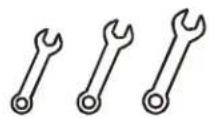
7/16"
2
PARTS

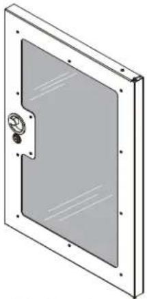
A (1) [Door]
natural_image
Technical line drawing of a rectangular panel with a central handle and mounting holes (no text or symbols)[Plexiglass]
OR

natural_image
Exterior view of a rectangular panel with a black cover and mounting holes (no text or symbols)[Perforated] [Solid]
(NS1D12F shown)

natural_image
Simple line drawing of a rectangular panel with a circular button and label 'OR' on the side (no text or symbols on the panel itself)(NS1D12S shown)
(NS1D12P shown)
![C (1) [Top door support]](/content/2026/06/1190621/images/b939b1f8fb15d866225d8e12c862f1942e7cd06ebdcdc975ef9d5ca0043a5675.jpg)
![E (2) 1/4-20 x 5/ D (1) [Lower door support]](/content/2026/06/1190621/images/78217e6aa03b3f3e757eb5efd9dadbdf09ff26749b4654b273b7546800de7cd1.jpg)

E (2)
1/4-20 x 5/8"

F (2)
1/4-20
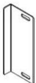
B (1)
por catch]
INSTALLATION
IMPORTANT ! : If installing doors and side panels (not included) on an S1 rack, the doors must be installed before installing the side panels.
- Remove and save four screws from both top and bottom of rack front. (See Figure 1)

Figure 1
- Add top door support (C) and lower door support (D) to rack front. (See Figure 4)
- Attach door supports using eight screws removed in Step 1.
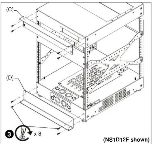
Figure 2
IMPORTANT ! : If the door is to be attached with the pulling handle on the right side, the two nuts and grounding wire already installed on the door must be removed and reinstalled on the opposite end of the door before the door is installed. The grounding wire should be on the BOTTOM of the installed door. (See Figure 3)

Figure 3
- Rotate two spring handles (one at bottom and one at top) on inside of door. (See Figure 4)
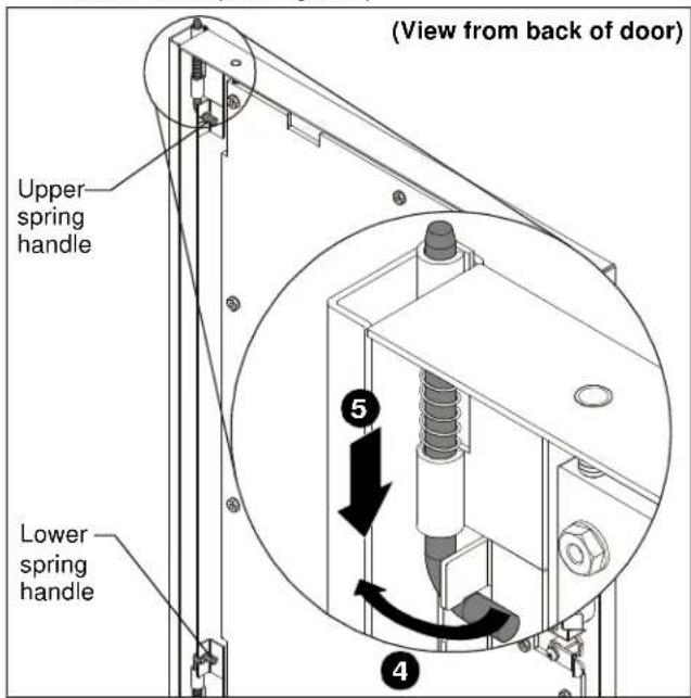
Figure 4
- Pull down on upper spring handle, and push up on lower spring handle.
- Insert door into rack, aligning the spring handle ends with the holes in the door support at top and bottom of rack. (See Figure 5)
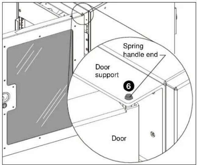
Figure 5
- Push spring handle end into door supports, and re-latch spring handle.
- Determine location for door catch (B) by matching up handle cut-out in door with correct position on rack. (See Figure 6)

natural_image
Technical line drawing of a server rack cabinet with mounting holes and a numbered component (no text or symbols)Figure 6
9. Add door catch (B) to rack rail using two 1/4-20 x 5/8" screws (E) and two 1/4-20 lock nuts (F). (See Figure 7)

Figure 7
10. Loosen screw in lower door support, attach door grounding wire, and tighten screw to finish connection. (See Figure 8)

Figure 8

Figure 9

DANGER: IMPROPER WIRING CAN LEAD TO DEATH OR SEVERE PERSONAL INJURY! Grounding must be installed by qualified personnel using a UL Recognized No. 12AWG Green and Yellow grounding wire connected to grounding lug on rack.
NS1D12-20-28-36-41
Installation Instructions


Brand : Chief
Model : NS1D12F
Category : Unspecified