
CGG302FFC - Cooker BLANCO - Free user manual and instructions
Find the device manual for free CGG302FFC BLANCO in PDF.

| Product Type | Freestanding Cooker |
| Brand | BLANCO |
| Model | CGG302FFC |
| Energy Source | Gas |
| Oven Fuel | Gas |
| Number of Burners | 4 |
| Oven Capacity | Approx. 65 L |
| Dimensions (H x W x D) | 850 mm x 600 mm x 600 mm |
| Weight | Approx. 50 kg |
| Power Supply | 220-240 V, 50 Hz |
| Gas Connection | Natural Gas or LPG (convertible) |
| Oven Functions | Conventional heating, grill |
| Ignition | Automatic electric ignition |
| Safety Features | Flame failure device, oven door lock |
| Cleaning | Easy-clean enamel interior |
| Control Type | Knobs |
| Display | Analog timer |
| Energy Efficiency Class | A |
| Spare Parts Availability | Yes, through authorized service centers |
| Warranty | 2 years |
Frequently Asked Questions - CGG302FFC BLANCO
User questions about CGG302FFC BLANCO
0 question about this device. Answer the ones you know or ask your own.
Ask a new question about this device
Download the instructions for your Cooker in PDF format for free! Find your manual CGG302FFC - BLANCO and take your electronic device back in hand. On this page are published all the documents necessary for the use of your device. CGG302FFC by BLANCO.
USER MANUAL CGG302FFC BLANCO
USE, INSTALLATION AND MAINTENANCE INSTRUCTIONS FOR BUILT-IN HOT PLATES
Dear Customer
Thank you for purchasing a Blanco Cooktop.
Before we continue telling you about this cooktop, we cordially invite you to become part of the Blanco family by subscribing to ongoing information and invitations. Please visit our website where you can subscribe and request such things as invitations to future cooking classes and gourmet recipes. Go to www.blanco-australia.com and fill in the subscription details.
You will find that the clean lines and modern look of your Blanco Cooktop blends perfectly with your kitchen décor. It is easy to use and performs to a high standard.
Blanco also makes a range of products that will enhance your kitchen such as ovens, rangehoods, dishwashers, microwaves, sinks and taps.
There are models to complement your new Blanco Cooktop.
Of course we make every effort to ensure that our products meet all your requirements, and our Customer
Relations department is at your disposal, to answer your questions and to listen to all your suggestions (see back cover of manual).
Please complete the warranty section of this manual and keep your receipt as proof of purchase. Retain all documents relating to the purchase of this products.
Blanco is committed to providing increasingly efficient products that are easy to use, respect the environment and are attractive and reliable.
BLANCO
BLANCO
MODELS: CGG302FFC - CGG452FFC
CGG604WFFC - CGG704WCP
CGG704WFFCP - CGG705WFFC
CGG905WFFC
BLANCO
We ask that you carefully read the instructions within this booklet to enable you to abtain quality results from the outset.
The appliance must be installed only by an authorised person in compliance with the instructions provided. The manufacturer declines all responsibility for improper installation which may harm persons and animals and damage property.
The appliance must be used for the purpose for which it was expressly designed. Any other use (eg heating rooms) is considered to be improper and consequently dangerous. The manufacturer declines all responsibility for damage resulting from improper and irresponsible use.
The manufacturer shall not be held responsible for any inaccuracies in this handbook due to printing or transcription errors. The designs in the figures are purely indicative.
The manufacturer also reserves the right to make any modifications to the products as may be considered necessary, useful or in the interests of the user, without jeopardizing the main functional and safety features on the products themselves.
If your cooktop requires service, please contact your local customer service centre or your nearest Blanco agent listed at the back of this booklet. COD. 04067GGB - 27.01.2011
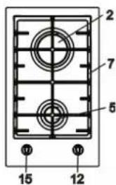
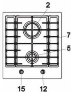
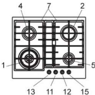
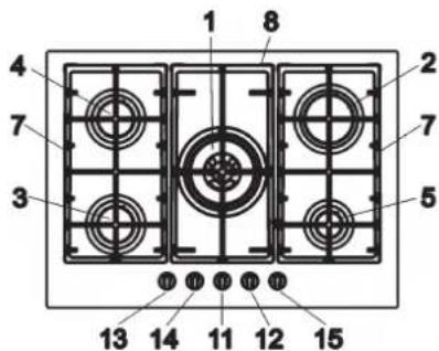
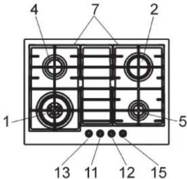
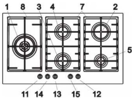
DESCRIPTION OF HOBS
Natural Propane
1 Ultra rapid gas burner/WOK 17.0 MJ/h 16.2 MJ/h
2 Rapid gas burner 12.0 MJ/h 10.4 MJ/h
3 Semirapid red. gas burner 5.4 MJ/h 4.86 MJ/h
4 Semirapid gas burner 7.1 MJ/h 6.3 MJ/h
5 Auxiliary gas burner 4.1 MJ/h 3.6 MJ/h
7 Cast iron trivet pan support 2F
8 Cast iron trivet pan support central
11 Burner n° 1 control knob
12 Burner n° 5 control knob
13 Burner n° 4 control knob
14 Burner n° 3 control knob
15 Burner n° 2 control knob
Attention: this appliance has been manufactured for domestic use only. Do not modify this appliance.
USE
1) BURNERS
A diagram is screen-printed above each knob on the front panel. This diagram indicates to which burner the knob in question corresponds. After having opened the gas mains or gas bottle tap, light the burners as described below:
- automatic electrical ignition
Push and turn the knob corresponding to the required burner in an anticlockwise direction until it reaches the full on position (large flame fig. 1), then depress the knob.
- Lighting burners equipped with flame failure device
The knobs of burners equipped with flame failure device must be turned in an anticlockwise direction until they reach the full on position (large flame fig. 1) and come to a stop. Now depress the knob in question and repeat the previously indicated operations.
Keep the knob depressed for about 10 seconds once the burner has ignited.
Note: you are advised not to try and light a burner if the flame divider (burner Cap) is not correctly placed
In the event of the Burner flames being accidentally extinguished, turn off the burner control and do not attempt to re-ignite the burner for a least 1 minute.
HOW TO USE THE BURNERS
Bear in mind the following indications in order to achieve maximum efficiency with the least possible gas consumption:
- use adequate pans for each burner (consult the following table and fig. 2).
- When the pan comes to the boil, set the knob to the reduced rate position (small flame fig. 1).
- Always place a lid on the pans.
- Use only pan with a flat bottom.
| Burners | Power ratings | Pan ∅ in cm | |
| Natural Propane | |||
| Ultra rapid/WOK | 17.0 MJ/h | 16.2 MJ/h | 24 ÷ 26 |
| Rapid 12.0 MJ/h | 10.4 MJ/h | 20 ÷ 22 | |
| Semirapid red. | 5.4 MJ/h | 4.86 MJ/h | 16 ÷ 18 |
| Semirapid | 7.1 MJ/h | 6.3 MJ/h | 16 ÷ 18 |
| Auxiliary | 4.1 MJ/h | 3.6 MJ/h | 10 ÷ 14 |
WARNINGS:
- burners with flame failure device may only be ignited when the relative knob has been set to the Full on position (large flame fig. 1).
- Matches can be used to ignite the burners in a blackout situation.
- Never leave the appliance unattended when the burners are being used. Make sure there are no children in the near vicinity. Particularly make sure that the pan handles are correctly positioned and keep a check on foods requiring oil and grease to cook since these products can easily catch fire.
- The machine must not be used by people (including children) with impaired mental or physical capacities, or without experience of using electrical devices, unless supervised or instructed by an expert adult responsible for their care and safety. Children should not be allowed to play with the equipment.
- Never use aerosols in the vicinity of this appliance while it is in operation.
- Should a crack appear on the surface of the glass, disconnect the appliance from the electricity supply immediately.
- Do not place pans with an unstable or deformed bottom on the burner, as these may tip or spill their contents, causing accidents.
- Do not store or use flammable liquids or items in the vicinity of the hotplate.
- Do not use the hob as a work surface.
- This product is not to be installed in marine crafts, caravans, or mobile homes.
- Containers wider than the unit are not recommended.
- Avoid scraping the pans on the glass surface, as the surface may become scratched.
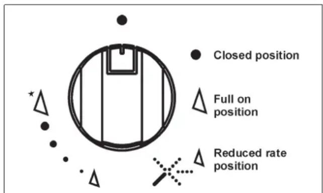
FIG. 1 FIG. 2
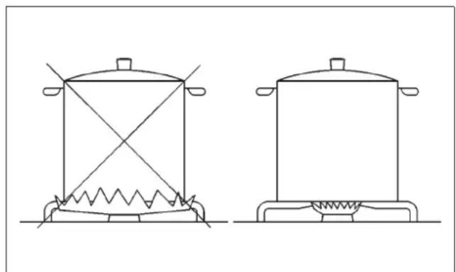
natural_image
Line drawing of two identical cooking pots with heating elements, no text or symbols presentUSE
Notes:
use of a gas cooking appliance produces heat and moisture in the room in which it is installed. The room must therefore be well ventilated by keeping natural air vents clear and by activating a mechanical aeration device (suction hood or electric fan).
Intensive and lengthy use of the appliance may require additional ventilation. This can be achieved by opening a window or by increasing the power of the mechanical exhausting system if installed.
Abnormal operations:
any of the following are considered to be anormal operation and may require servicing:
- yellow tipping of the hob burner flame.
- Sooting up of cooking utensils.
- Burners not igniting properly.
- Burners failing to remain alight.
- Burner extinguished by cupboard doors.
- Gas valves which are difficult to turn.
Symbol 1
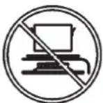
Do not place anything, eg. flame tamer, asbestos mat, between pan and pan support as serious damage to the appliance my result.
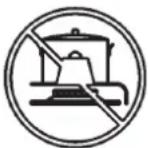
Symbol 2

Do not remove the pan support and enclose the burner with a wok stand as this will concentrate and deflect heat onto the hotplate.
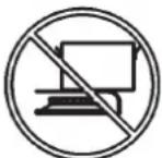
Symbol 3
Do not use large pots or heavy weights which can bend the pan support or deflect flame onto the hotplate.
Symbol 4
Locate pan centrally over the burner so that it is stable and does not overhang the appliance.
Symbol 5

Use only a wok support supplied or recommended by the manufacturer of the appliance.
CLEANING
IMPORTANT:
always disconnect the appliance from the gas and electricity mains before carrying out any cleaning operation.
2) HOT PLATE
Periodically wash the hot plate, the enamelled steel pan support, the enamelled burner caps "C" and the burner heads "M" (see fig. 3) with lukewarm soapy water. Following this, all parts should be thoroughly rinsed and dried. Never wash them while they are still warm and never use abrasive powders.
Do not allow vinegar, coffee, milk, salted water, lemon or tomato juice from remaining in contact with the surfaces for long periods of time.
WARNINGS:
comply with the following instructions, before remounting the parts:
- check that burner head slots "M" (fig. 3) have not become clogged by foreign bodies.
- Check that the enamelled burner cap "C" (fig. 3) has been correctly positioned on the burner head. It must be steady.
- Do not force the taps if they are difficult to open or close. Contact an Authorised Service Centre for repairs.
- Don't use steam jets for cleaning the cooktop.
PREVENTATIVE MAINTENANCE
This cooktop should not require ongoing maintenance provided you ensure:
- all spillages are cleaned up as soon as they occur.
- Burner are kept clean.
- Burner ports are free of debris, food or anything else that may cause an obstruction.
- Electrode and thermocouples are kept clean.
- Burners are re-assembled correctly.
- Do not get water in the area where the injectors are located.
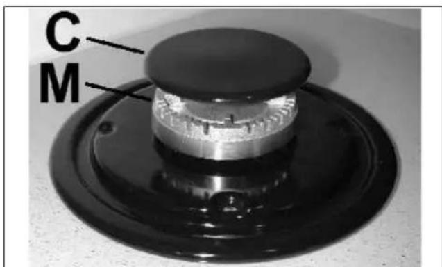
FIG. 3
INSTALLATION
TECHNICAL INFORMATION FOR THE INSTALLER
This appliance shall be installed only by authorised personnel and in accordance with the manufacturer's installation instructions, local gas fitting regulations, municipal codes, electrical wiring regulations, AS 5601 - Gas Installation and any statutory regulations. Ventilation must be in accordance with AS 5601 - Gas installation. In general, the appliance should have adequate ventilation for complete combustion of gas, proper flueing and to maintain temperature of immediate surroundings safe limits.
The wall and bench surfaces must be capable of sustaining temperatures of 75 °C. All laminates, fixing adhesive and surfacing materials should be certified suitable for this temperature.
CAUTION:
the installer shall test the appliance before leaving. Test the safety operation of the ignition system on all burners individually and combined.
3) INSTALLING THE HOT PLATE
Check that the appliance is in a good condition after having removed the outer packaging and internal wrappings from around the various loose parts. In case of doubt, do not use the appliance and contact qualified personnel.
other Never leave the packaging materials (cardboard, bags, polystyrene foam, nails, etc.) within children's reach since they could become potential sources of danger.
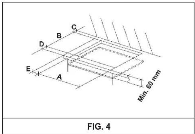
The measurements of the opening made in the top of the modular cabinet and into which the hot plate will be installed are indicated in either fig. 4. Always comply with the measurements given for the hole into which the appliance will be recessed (see fig. 4).
The appliance belongs to class 3 and is therefore subject to all the provisions established by the provisions governing such appliances.
Any adjoining wall surface situated within 200 mm from the edge of any hob burner must be a suitable non-combustible material for a height of 150 mm for the entire length of the hob. Any combustible construction above the top of the burner and no construction shall be within 450 mm above the top of the burner. A minimum depth of 60 mm from the top of the work surface must be provided for this appliance.
COMPLY WITH THE DIMENSION(Smm)
| A | B | C | D | E | |||
| 2F (30) | 285 | 473 | 59 | 59 100 | min. | ||
| 2F (45) | 285 | 473 | 63.5 | 63.5 | 117 min. | ||
| 4F (60) | 553 | 473 | 63.5 | 63.5 | 173.5 | min. | |
| 4F - 5F (70) | 645 | 473 | 63.5 | 63.5 | 173.5 | min. | |
| 5F (90) | 833 | 475 | 62.5 | 62.5 | 73.5 | min. | |
CAUTION:
do not place the glass directly on the unit. The bottom of the hob must rest on the unit.
INSTALLATION
4) FIXING THE HOT PLATE
The hot plate has a special seal which prevents liquid from getting into the cabinet. Strictly comply with the following instructions in order to correctly apply this seal:
- take off all the movable parts of the hob.
- Cut the seal in 4 parts of the necessary lenght to positioning it on the 4 edges of the glass.
- Overturn the hot plate and correctly position seal "E" (fig. 5) under the edge of the hot plate itself, so that the outer side of the seal perfectly matches the outer edge of the hot plate. The ends of the strips must fit together without overlapping.
- Evenly and securely fix the seal to the hot plate, pressing into place with the fingers and remove the strip of protective paper from the seal and set the plate into the hole made in the cabinet.
- Position the hob in the hole in the unit and fasten it in place using the appropriate screws "F" and the fastening hooks "G" (fig. 6).
- When the appliance is installed so that the base can be touched, we recommend fitting a protecting shield. This shield must be at least 60 mm below the base of the bench top (fig. 4). Timber or other suitable material may be used provided it is capable of withstanding the appliance temperatures. Ensure that the supply connection point is accessible with the appliance installed. To facilitate the shield may need to be removable.
NOTE: do not fix the cooktop into the bench with sealant (ie silicon) as this may void the warranty. Use only the seals provided.
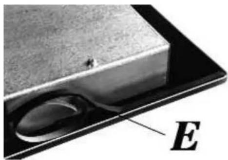
FIG. 5
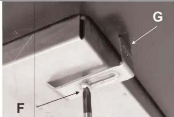
FIG. 6
INSTALLATION
5) GAS CONNECTION
The gas connection is located in the rear and on the underside of the appliance 100 mm from the right hand side.
There are two ways to carry out the connection to the main gas line:
A. The hotplate can be connected with rigid pipe as specified in AS5601 table 3.1.
B. If installing with a hose assembly, install with a hose assembly that complies with AS/ANZ 1869 (AGA Approved), 10 mm ID, class B or D, no more than 1.2 m long and in accordance with AS5601. Ensure that the hose does not contact the hot surfaces of the hotplate, oven, dishwasher or any other appliance that may be installed underneath or next to the hotplate. The hose should not be subjected to abrasion, kinking or permanent deformation and should be able to be inspected along its entire length with the cooktop in the installed position.
Unions compatible with the hose fittings must be used and all connections tested for gas leaks.
The gas supply connection for the hose assembly must be accessible.
Warning: ensure that the hose assembly is restrained from accidental contact with the flue or flue outlet of an underbench oven.
Natural Gas
Natural Gas installations require the connection of a gas regulator at the appliance. This regulator is supplied with the appliance on purchase.
Assemble the regulator (noting the gas flow direction) and transition pieces (supplied with the appliance), in accordance with figure 7.
The transition piece on the supply side of the regulator must be provided by the installer.
Liquified Petroleum Gas
In a Propane Gas installation the gas regulation is made at the gas cylinder and regulation at the appliance is not required. To connect supply to the appliance use transition pieces as shown in figure 8. These pieces are supplied with the appliance on purchase.
WARNING:
THE BURNER FLAME MUST BE ADJUSTED BY THE INSTALLER.
FAULTY INSTALLATION WILL NOT BE
COVERED UNDER WARRANTY.
THE APPLIANCE IS FACTORY SET FOR
NATURAL GAS. THE TEST POINT PRESSURE
The appliance is supplied with a 1800 mm long flexible supply lead.
The point of attachment for this lead is located at the rear and on the underside of the appliance 380 mm from the right hand side.
The voltage and power consumption are detailed on the underside of the appliance. Ensure that the appliance is correctly rated to the supply.
Connect appliance by way of a switched power point.
THE APPLIANCE MUST BE EARTHED
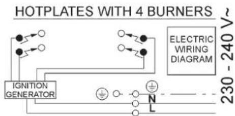
Ensure that this power point is properly earthed. Look at the connection wiring diagrams (fig. 9, 9/A and 9/B).
Warning: in order to avoid hazard, any electrical work performed on this equipment or its associated wiring, should only be done by persons authorised by the supplier or similarly qualified persons.
The socket outlet for this hotplate shall be installed near the hotplate and shall be easily accessible.
CAUTION!
The manufacturer cannot be responsible for the missing earthing of the appliance.
Electrical connection must be carried out in compliance with local regulations.
This appliance must be connected directly to the mains supply.
Ensure the appliance is installed by an authorised person in accordance with AS/NZS 3000 wiring rules.
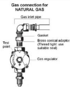
FIG. 7

FIG. 8
ADJUSTMENTS
Always disconnect the appliance from the electricity main before making any adjustments. All seals must be replaced by the technician at the end of any adjustments or regulations. Our burners do not require primary air adjustment.
a) Data Label
The Data Label is located on the underside of the hotplate. A duplicate Data Label is supplied to adhere in an accessible area next to the hotplate. This hotplate is suitable for Natural Gas and Propane Gas; ensure that the available gas supply matches the Data Label.
b) Before Leaving
Check that there are no gas leaks, but do not use a naked flame to detect gas leaks. Ignite all burners to ensure correct operation of gas valves, burners, ignition and if fitted, flame failure valves. Turn gas taps to low flame position and observe stability of the flame. When satisfied with the hotplate, please instruct the user on the correct method of operation. In case the appliance fails to operate correctly after all checks have been carried out, refer to the authorised service provider in your area.
7) TAPS
Our taps are suitable for all gas, they are male conical type.
"Reduced rate" adjustment
- Switch on the burner and turn the relative knob to the "Reduced rate" position (small flame fig. 1).
- Remove knob "M" (fig. 10) of the tap, which is simply pressed on to its rod.
- Insert a small screwdriver "D" into hole "C" (fig. 10) and turn the throttle screw to the right or left until the burner flame has been adequately regulated to the "Reduced rate" position.
Check that the flame does not go out when the knob is sharply switched from the "Full on" to the "Reduced rate" position.
It is understood that only burners operating with Natural gas should be subjected to the above mentioned adjustments. The screw must be fully locked when the burners operate with Liquid gas.
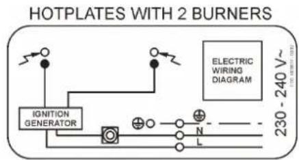
FIG. 9
flowchart
graph TD
    A["IGNITION GENERATOR"] --> B["230 - 240 V"]
    C["230 - 240 V"] --> D["230 - 240 V"]
    E["230 - 240 V"] --> F["230 - 240 V"]
    G["230 - 240 V"] --> H["230 - 240 V"]
    I["230 - 240 V"] --> J["230 - 240 V"]
    K["230 - 240 V"] --> L["230 - 240 V"]
    M["230 - 240 V"] --> N["230 - 240 V"]
    O["230 - 240 V"] --> P["230 - 240 V"]
    Q["230 - 240 V"] --> R["230 - 240 V"]
    S["230 - 240 V"] --> T["230 - 240 V"]
    U["230 - 240 V"] --> V["230 - 240 V"]
    W["230 - 240 V"] --> X["230 - 240 V"]
    Y["230 - 240 V"] --> Z["230 - 240 V"]
    AA["230 - 240 V"] --> AB["230 - 240 V"]
    AC["230 - 240 V"] --> AD["230 - 240 V"]
    AE["230 - 240 V"] --> AF["230 - 240 V"]
    AG["230 - 240 V"] --> AH["230 - 240 V"]
    AI["230 - 240 V"] --> AJ["230 - 240 V"]
    AK["230 - 240 V"] --> AL["230 - 240 V"]
    AM["230 - 240 V"] --> AN["230 - 240 V"]
    AO["230 - 240 V"] --> AP["230 - 240 V"]
    AQ["230 - 240 V"] --> AR["230 - 240 V"]
    AS["230 - 240 V"] --> AT["230 - 240 V"]
    AU["230 - 240 V"] --> AV["230 - 240 V"]
    AW["230 - 240 V"] --> AX["230 - 240 V"]
    AY["1"] --> AZ["1"]
    BA["1"] --> BB["1"]
    BC["1"] --> BD["1"]
    BE["1"] --> BF["1"]
    BG["1"] --> BH["1"]
    BI["1"] --> BJ["1"]
    BK["1"] --> BL["1"]
    BM["1"] --> BN["1"]
    BO["1"] --> BP["1"]
    BQ["1"] --> BR["1"]
    BS["1"] --> BT["1"]
    BU["1"] --> BV["1"]
    BW["1"] --> BX["1"]
    BY["1"] --> BZ["1"]
    CA["1"] --> CB["1"]
    CC["1"] --> CD["1"]
FIG. 9/A
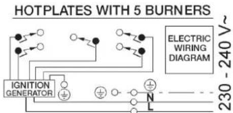
FIG. 9/B
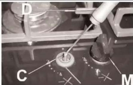
FIG. 10
CONVERSIONS
Appliance models: Gas stainless steel hotplate models:
| CGG302FFC | 2 Burners |
| CGG452FFC | 2 Burners |
| CGG604WFFC | 4 Burners |
| CGG704WCP | 4 Burners |
| CGG704WFFCP | 4 Burners |
| CGG705WFFC | 5 Burners |
| CGG905WFFC | 5 Burners |
- Remove each burner cap and burner skirt.
- Remove the Propane Gas main injector with a 7 mm/VF tube spanner and replace with the appropriate size Natural Gas injector for each burner. The following injector sizes are required for Natural Gas:
Burner Main injector
Semi Rapid Reduced 1.05 mm
Semi Rapid 1.20 mm
Auxiliary 0.90 mm
- Shut off gas supply to the appliance.
- Disconnect gas inlet pipe from the Propane Gas test point inlet fitting.
- Remove the Propane Gas test point inlet fitting from the appliance.
- Fit the Natural Gas Regulator supplied in the conversion kit.
- Connect the gas supply to the Regulator.
- Check for gas leaks. Do not use a naked flame to check for gas leaks.
- Adjust the gas pressure to 1.00 kPa.
- Remove the control knob, with a thin shaft blade screwdriver down the centre of each gas valve shaft, screw the by-pass injector anti-clockwise. Test the appliance on both high and low flame for each burner. If the burner fails to remain alight or the flame is not stable on the simmer setting, adjust the by-pass screw, until flame is stable.
- If not already removed, remove the "Only for use with Propane Gas" label adhered to the bottom panel near the gas connection.
- Fit the new data label included in the gas conversion kit.
Appliance models: Gas stainless steel hotplate models:
| CGG302FFC | 2 Burners |
| CGG452FFC | 2 Burners |
| CGG604WFFC | 4 Burners |
| CGG704WCP | 4 Burners |
| CGG704WFFCP | 4 Burners |
| CGG705WFFC | 5 Burners |
| CGG905WFFC | 5 Burners |
- Remove each burner cap and burner skirt.
- Remove the Natural Gas main injector with a 7 mm/VF tube spanner and replace with the appropriate size Propane Gas main injector for each burner. The following injector sizes are required for Propane Gas:
Burner Main injector
Wok 2 x 0.72 B + 0.50 Bmm
Rapid 0.91 mm
Semi Rapid Reduced 0.60 mm
Semi Rapid 0.70 mm
Auxiliary 0.53 mm
- Remove the control knob, with a thin shaft blade screwdriver down the centre of each gas valve shaft, screw the by-pass injector fully clockwise.
- Shut off gas supply to the appliance.
- Disconnect gas inlet pipe from the Natural Gas Regulator.
- Remove the Natural Gas Regulator from the appliance.
- Fit the Propane Gas test point inlet fitting supplied in the conversion kit.
- Connect the gas supply to the inlet fitting.
- Check for gas leaks. Do not use a naked flame to check for gas leaks.
- Adjust the gas pressure to 2.75 kPa.
- Test the appliance on both high and low flame for each burner and check the gas pressure. If the burner fails to remain alight or the flame is not stable on the simmer setting, adjust the by-pass screw, until flame is stable.
- If not already removed, remove the "Only for use with Natural Gas" label adhered to the bottom panel near the gas connection.
- Fit the new data label included in the gas conversion kit.
CONVERSIONS
10) REPLACING THE INJECTORS
The burners can be adapted to different types of gas by installing injectors suited to the type of gas required. To do this, first remove the burner tops using a wrench "B". Now unscrew injector "A" (see fig. 11) and fit a injector corresponding to the type of gas required.
It is advisable to tighten the injector in place.
After the injectors have been replaced, the burners must be regulated as explained in paragraphs 7. The technician must reset any seals on the regulating or pre-regulating devices
and affix the label corresponding to the new gas regulation on the appliance instead of the already existing one. This label is supplied in the packet containing the spare injectors.
The envelope with the injectors and the labels can be included in the kit, or at disposal to the authorised customer Service Centre.
For the sake of convenience, the nominal rate chart also lists the heat inputs of the burners, the diameter of the injectors and the working pressures of the various types of gas.
BURNER ARRANGEMENT ON THE HOT PLATE
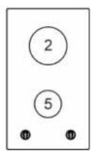
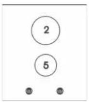
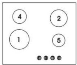
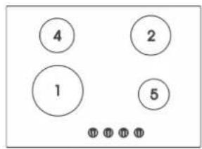
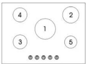
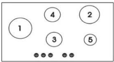
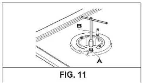
TABLE 1
| BURNERS | GAS | NORMAL PRESSURE (kPa) | INJECTOR DIAMETER (1/100 mm) | NOMINAL HEAT INPUT (MJ/h) MAX. | BY PASS | |
| N° | DESCRIPTION | 1/100 mm | ||||
| 1 | ULTRA RAPID | PROPANE NATURAL | 2.75 1.00 | 2 x 72 B + 50B 2 x 123 B + 80B | 16.2 17.0 | 85 1/2 |
| 2 | RAPID | PROPANE NATURAL | 2.75 1.00 | 91 155 | 10.4 12.0 | 45 5/8 |
| 3 | SEMIRAPID REDUCED | PROPANE NATURAL | 2.75 1.00 | 60 105 | 4.86 5.4 | 35 1/2 |
| 4 | SEMIRAPID | PROPANE NATURAL | 2.75 1.00 | 70 120 | 6.3 7.1 | 35 1/2 |
| 5 | AUXILIARY | PROPANE NATURAL | 2.75 1.00 | 53 90 | 3.6 4.1 | 32 3/8 |
SERVICING
WARNING:
servicing should be carried out only by authorised personnel.
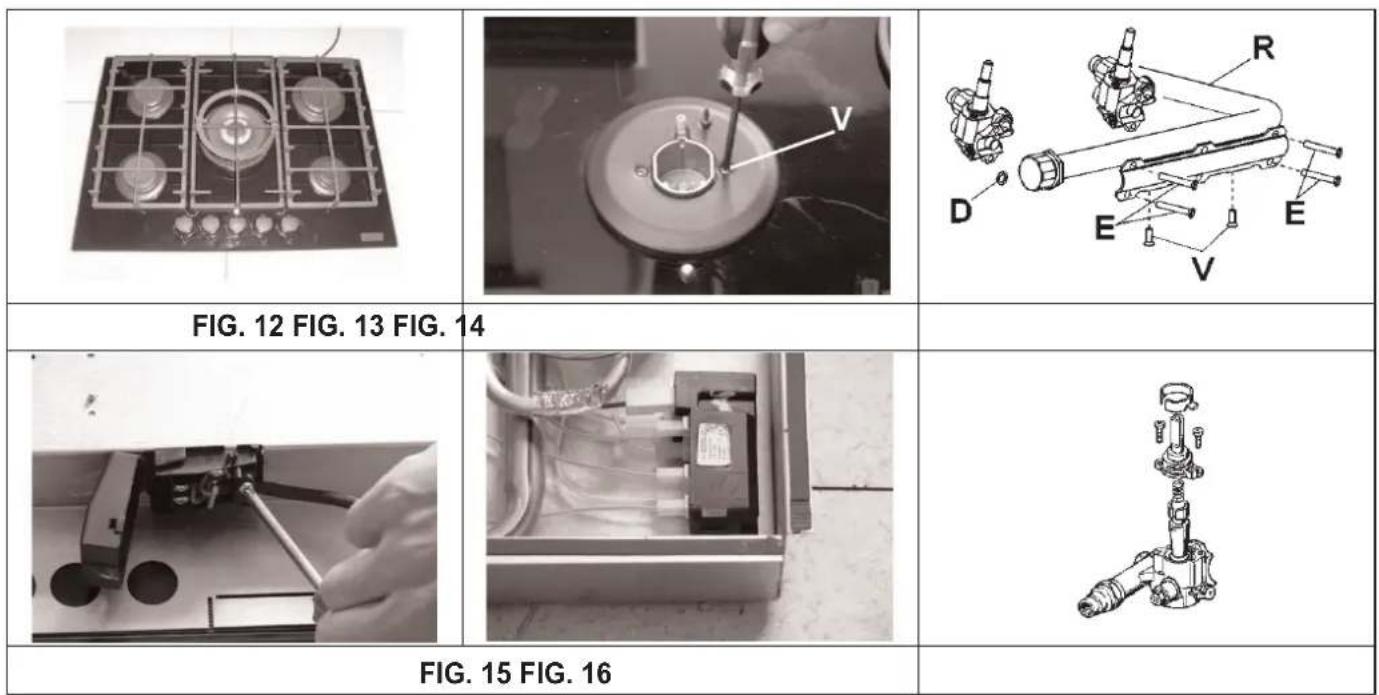
11) COMPONENT REPLACEMENT NOTE:
BEFORE ANY MAINTENANCE REQUIRING REPLACEMENT OF A COMPONENT IS UNDERTAKEN ENSURE THAT THE ELECTRICAL LEAD HAS BEEN ISOLATED AND REMOVED FROM THE POWER POINT.
Replacement of the components housed inside the appliance: remove the trivets, knobs and flanges unscrewing the screws "V" and remove the glass (see fig. 12).
After having carried out the above listed operations, the burners (fig. 13), taps (fig. 14) and electrical components can all be replaced (fig. 15). It is advisable to change seal "D" whenever a tap is replaced to ensure a perfect tightness.
Greasing the taps (see fig. 16)
If a tap becomes stiff to operate, it must be immediately greased in compliance with the following instructions:
- remove the tap.
- Clean the cone and its housing using a cloth soaked in diluent.
- Lightly spread the cone with the relative grease.
- Fit the cone back in place, operate it several times and then remove it again. Eliminate any excess grease and check that the gas ducts have not become clogged.
- Fit all parts back in place, complying with the demounting order in reverse.
- The tight closure test must be done using a foamy liquid. The use of the flame is prohibited.
To facilitate the servicing technician's task, here is a chart with the types and sections of the powering cables and the ratings of the electrical components.
SERVICING
CABLE TYPES AND SECTIONS
| TYPE OF TYPE OF SINGLE - PHASEHOT PLATE CABLE POWER SUPPLY | |
| Gas hot plate H05 RR - F Section 3 x 0.75 mm | 2 |
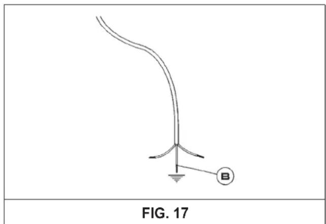
ATTENTION!!!
If the power supply cable is replaced, the installer should leave the ground wire longer than the phase conductors (fig. 17) and comply with the recommendations given in paragraph 6.
BLANCO CUSTOMER SERVICE 1300 739 033
www.meaappliances.com.au
SALES OFFICES AND SHOWROOMS
SERVICE AND SPARE PARTS
NEW SOUTH WALES. QUEENSLAND.
Head Office, Sales and Marketing Brisbane.
104 Vanessa Street. Endeavour Refrigeration and Appliance Service.
Kingsgrove. Telephone: 07 3137 3633
NSW 2208. Facsimile: 07 3137 3663
Telephone: 02 9503 2888
Facsimile: 02 9503 2810
www.endeavourservice.com.au
Gold Coast.
Sydney Showroom. Roshad Appliance Service.
40 Ebley Street. Telephone: 07 5535 7044
Bondi Junction. Facsimile: 07 5535 7407
NSW 2022
Telephone: 02 9386 1190
Facsimile: 02 9386 1671
Sunshine Coast.
Paul Matters Electrical
Telephone: 07 5449 7133
Facsimile: 07 5449 9045
QUEENSLAND
Brisbane Showroom.
148 Robinson Road East.
Geebung
QLD 4034.
Telephone: 07 3259 2555
Facsimile: 07 3265 6933.
NEW SOUTH WALES.
All General Whitegoods.
Telephone: 02 8788 8666
Facsimile: 02 9752 5294
www.agw.com.au
VICTORIA.
Melbourne Showroom.
35 Centre Road.
Scoresby
VIC 3179
Telephone: 03 8756 7888
Facsimile: 03 8756 7907
AUSTRALIAN CAPATIAL TERRITORY
Detlevs Appliance & Electrical Care
Telephone: 02 6260 1033
Facsimile: 02 6260 1035
VICTORIA.
South Australia Showroom (By Appointment only)
SC Lighting & Electrical Supplies
47 North Terrace
Hackney
SA 5069
Telephone: 08 8362 4599
Facsimile: 08 8362 4591
Advantage Appliance Service
Telephone: 03 9874 4222
Facsimile: 03 9874 6917
Western Australia Sales Office
2A/1 King Edward Road,
Osborne Park,
WA 6017
Telephone: 08 9446 5299
Facsimile: 08 9204 1219
SOUTH AUSTRALIA
Prestige Appliance
Telephone: 08 8352 2022
Facsimile; 08 8352 2044
www.prestigerepairs.com.au
*SHOWROOMS ARE OPEN 6 DAYS A WEEK.
WESTERN AUSTRALIA
Metropolitan Appliance Service
Telephone: 08 9330 1724
Facsimile: 08 9317 1296
WARRANTY SECTION
BLANCO
BLANCO COOKING PRODUCT WARRANTY
- Subject to the "Statement of Standard Warranty Conditions" this product is covered by the following Warranty.
TWO (2) YEARS WARRANTY from date of purchase, covering all parts and labour.
-
The appliance is warranted under normal single family domestic installation and use, as set out in the instruction manual, against manufacturing defects for the Warranty periods shown above.
-
Should service be required under this Warranty, the purchaser should contact an approved BLANCO Service Provider during their normal business hours.
-
At no time does BLANCO/MEA have liability for any freight or transportation costs or for any damage during transit or for any consequence of failure of this appliance outside of the normal service area, unless such limitation of liability is prohibited by statute.
-
This Warranty excludes replacement of parts required due to normal wear and tear including light globe.
-
This Warranty only applies, provided the appliance has been used in accordance with the manufacturer's instructions and provided an accident, misuse, neglect or abuse has not damaged the appliance.
-
None of the above Warranties purport to exclude, restrict or modify either the application or the exercise of a right conferred by any applicable Statute.
-
Please complete the details below, which should be retained for future reference along with your proof of purchase:
Date of Purchase: ..... Model No: ..... Serial No: ....
Notice to Victorian Customers from the Victorian Plumbing Industry Commission.
This product must be installed by a licenced person as required by the Victorian Building Act 1993.
Only a licenced person will give you a Compliance Certificate, showing that the work complies with all the relevant standards. Only a licenced person will have insurance protecting their workmanship for 6 years. Make sure you use a licenced person to install this product and ask for your Compliance Certificate.
BLANCO
STATEMENT OF STANDARD WARRANTY CONDITIONS
-
The Warranty only applies provided that the appliance has been used in accordance with the manufacturer's instructions and provided that the appliance has not been damaged by an accident, misuse, neglect or abuse of any person other than the manufacturer or BLANCO/Major Electrical Appliances ("MEA") or from faulty installation, mis-adjustment or tampering by unauthorised persons.
-
When a service inspection reveals the alleged fault or faults are caused by incorrect operation, contrary to the instruction manual, and otherwise the appliance is in good order and working condition, the purchaser shall be liable for a service fee charged by BLANCO/MEA or one of its' Service Providers.
-
If the appliance is used in Commercial Applications or for Rental purposes, a separate warranty of Twelve (12) months covering all parts with Three (3) months on the labour will apply.
-
Subject to the provisions of any applicable statute this Warranty applies to the original retail purchaser only and is not transferable.
-
Subject to the provisions of any applicable statute, at no time does BLANCO/MEA have liability for freight, transport or travel costs outside normal service areas.
-
None of the above Warranties purport to exclude, restrict or modify either the application or the exercise of a right conferred by any applicable statute.
-
Subject to any Warranties implied by statute, at no time will BLANCO/MEA or its' Service Providers be liable for any economic loss consequent upon the failure of the appliance.
-
This Warranty is only valid for major appliances imported and distributed by BLANCO/MEA, purchased and used in Australia.

- USE, INSTALLATION AND MAINTENANCE INSTRUCTIONS FOR BUILT-IN HOT PLATES
- BLANCO
- DESCRIPTION OF HOBS
- USE
- 1) BURNERS
- - automatic electrical ignition
- - Lighting burners equipped with flame failure device
- HOW TO USE THE BURNERS
- WARNINGS:
- Notes:
- Abnormal operations:
- CLEANING
- IMPORTANT:
- 2) HOT PLATE
- PREVENTATIVE MAINTENANCE
- INSTALLATION
- TECHNICAL INFORMATION FOR THE INSTALLER
- CAUTION:
- 3) INSTALLING THE HOT PLATE
- 4) FIXING THE HOT PLATE
- 5) GAS CONNECTION
- Natural Gas
- Liquified Petroleum Gas
- WARNING:
- THE APPLIANCE MUST BE EARTHED
- CAUTION!
- ADJUSTMENTS
- a) Data Label
- b) Before Leaving
- 7) TAPS
- "Reduced rate" adjustment
- CONVERSIONS
- Burner Main injector
- 10) REPLACING THE INJECTORS
- SERVICING
- 11) COMPONENT REPLACEMENT NOTE:
- Greasing the taps (see fig. 16)
- ATTENTION!!!
- BLANCO CUSTOMER SERVICE 1300 739 033
- SALES OFFICES AND SHOWROOMS
- SERVICE AND SPARE PARTS
- NEW SOUTH WALES. QUEENSLAND.
- Head Office, Sales and Marketing Brisbane.
- Gold Coast.
- Sunshine Coast.
- QUEENSLAND
- Brisbane Showroom.
- NEW SOUTH WALES.
- VICTORIA.
- Melbourne Showroom.
- AUSTRALIAN CAPATIAL TERRITORY
- South Australia Showroom (By Appointment only)
- Western Australia Sales Office
- SOUTH AUSTRALIA
- WESTERN AUSTRALIA
- WARRANTY SECTION
- BLANCO COOKING PRODUCT WARRANTY
- TWO (2) YEARS WARRANTY from date of purchase, covering all parts and labour.
- Notice to Victorian Customers from the Victorian Plumbing Industry Commission.
- STATEMENT OF STANDARD WARRANTY CONDITIONS
Brand : BLANCO
Model : CGG302FFC
Category : Cooker