
FD9085FR - Cooker BLANCO - Free user manual and instructions
Find the device manual for free FD9085FR BLANCO in PDF.

| Product Type | Multi-fuel Freestanding Multifunction Cooker |
| Model Numbers | FD9085WX, FD9085FCR, FD9085FB, FD9085FR, FD9085FG, FD9085FX |
| Overall Dimensions (approx.) | Not specified in manual; typical freestanding cooker: 900mm width x 600mm depth x 900mm height |
| Weight (approx.) | Not specified in manual; typical: 80-100 kg |
| Electrical Connection | 15 Amp flexible cord and plug, earthed socket outlet |
| Rated Voltage / Frequency | 220-240 V / 50-60 Hz (standard Australian) |
| Total Rated Power | Upper 1100 W, Bottom 1500 W, Grill 2600 W, Circular 2600 W, Oven light 2x25 W |
| Gas Connection | Male 1/2" BSP, 55 mm from right, 565 mm from floor |
| Gas Types Supported | Natural Gas (test point 1.00 kPa) or Propane (test point 2.75 kPa) |
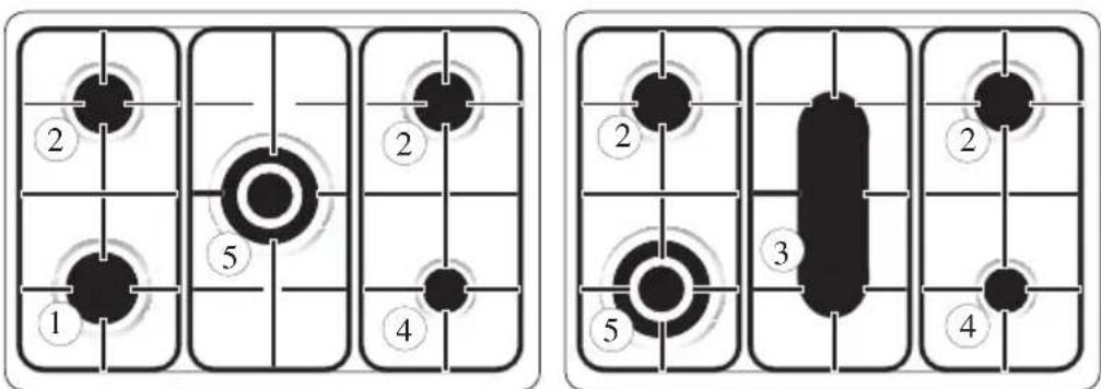
| Burners (5) | 1 Rapid, 2 Semi-rapid, 3 Fish/BBQ, 4 Auxiliary, 5 Wok |
| Burner Output (Natural Gas) | Rapid 11.0 MJ/h, Semi-rapid 6.9 MJ/h, Fish/BBQ 11.0 MJ/h, Auxiliary 3.8 MJ/h, Wok 15.0 MJ/h |
| Burner Output (Propane) | Rapid 10.8 MJ/h, Semi-rapid 6.3 MJ/h, Fish/BBQ 10.8 MJ/h, Auxiliary 3.8 MJ/h, Wok 12.9 MJ/h |
| Oven Functions | Lamp, Defrost, Traditional, Fan Assist, Bottom Element + Fan, Fan Forced, Grill, Fan Grill |
| Oven Temperature Range | 50°C to MAX (approx. 250°C) |
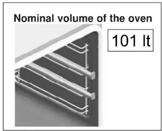
| Oven Capacity (approx.) | Not specified; typical freestanding oven: 100-120 L |
| Stabilising Chains | Yes, 2 chains for anti-tip, must be anchored to wall |
| Safety Features | Flame failure safety valve on burners, safety thermostat, electronic programmer with lock |
| Cleaning | Do not use steam jets; removable oven door and inner glass for cleaning; grill element can be lowered |
| Warranty | 2 years parts and labour for domestic use |
| Compliance | AS 5601 (Gas Installations), Australian electrical standards |
Frequently Asked Questions - FD9085FR BLANCO
User questions about FD9085FR BLANCO
0 question about this device. Answer the ones you know or ask your own.
Ask a new question about this device
Download the instructions for your Cooker in PDF format for free! Find your manual FD9085FR - BLANCO and take your electronic device back in hand. On this page are published all the documents necessary for the use of your device. FD9085FR by BLANCO.
USER MANUAL FD9085FR BLANCO
Instructions for the Use and Care and Installation of
FD9085WX
FD9085FCR
FD9085FB
FD9085FR
FD9085FG
FD9085FX
Multi-fuel Freestanding Multifunction Cookers
Dear Customer
Thank you for choosing our product.
Please read this hand book carefully before installing and using it, as you will find the correct indications for the best installation, use and care of the product.
You will find that the clean lines and modern look of your Blanco oven blends in perfectly with your kitchen décor. It is easy to use and performs to a high standard.
Blanco also makes a range of products that will enhance your kitchen – such as cooktops, rangehoods, dishwashers, microwaves, sinks and taps. There are models to complement your new Blanco oven.
Of course, we make every effort to ensure that our products meet all your requirements, and our Customer Service Centre is at your disposal to answer all your questions and to listen to all your suggestions.
Please complete the warranty section of this manual and keep your receipt as proof of purchase. Retain all documents relating to the purchase of your Blanco product.
Blanco is committed to providing increasingly efficient products that are easy to use, respect the environment and are attractive and reliable.
BLANCO
Index
GENERAL WARNINGS p. 5 - 8
Instructions for installation:
- Dimensions and installation features p. 9
• Electrical connection p. 10
• Ventilation and gas connection p. 11 - 12 - Adaptation to different types of gas p. 12
- Setting the minimum flame p. 13
- Burner and injector characteristic table p. 14
Instructions for use
• Description of the main parts of the appliance p. 15
- Ignition and operation of the burners p. 16
• Advice on the use of gas burners p. 17
- Oven function p. 18
- Component operation p. 19 - 21
Instructions for cooking
p. 22 - 23
Instructions for the assembly of bottom kick plate onto the cookers
p. 24
Maintenance and cleaning
p. 25 - 27
Blanco customer service
p. 28
Blanco product warranty.
p. 29
- Very important: keep this instruction booklet with the appliance in case you pass it on to someone else.
- This appliance is designed for non professional use by private individuals at home. It must be used by adults, do not allow children to play with it. The front accessible parts of the equipment could overheat during use.
- This appliance is not intended for use by young children or infirm persons without supervision.
- Young children should be supervised to ensure that they do not play with the appliance.
- Don't touch the heating elements inside the oven.
- When the grill is on all the accessible elements are hot, hence, keep children away from these elements.
- This appliance shall be installed only by authorised persons and in accordance with the manufacturer's installation instructions, local gas fitting regulations, municipal building codes, electrical wiring regulations, local water supply regulations, AS 5601 - Gas Installations and any other statutory regulations.
- Before switching the appliance on check that it is correctly regulated for the type of gas available (refer to page 11 and 12).
- Do not use the steams jets for cleaning.
- Before maintenance or cleaning disconnect the appliance from the mains and wait for it to cool down.
- When the burners are lit check that the flame is always regular. Before removing the saucepans turn the burners off.
- Servicing should be carried out only by authorised personnel.
General Warnings
- The use of a gas appliance produces heat and humidity in the room where it is installed. Make sure that the room is well ventilated, keeping the natural ventilation outlets open or installing a ventilation hood with drain duct.
- If a gas appliance is used for a long time it may require extra ventilation (opening a window or increase of the forced exhaust of rangehood).
- Be careful not to place saucepans with unstable or deformed bottoms on the burners to avoid accidents by overturning or spilling of liquid.
- If a burner is turned off accidentally turn off the control knob and try to light it again after waiting at least a minute.
Before using the oven for the first time, we suggest to:
- remove the special film covering the oven door glass (when provided)
- heat the empty oven at max. temperature for 45 minutes (to remove unpleasant smell and smoke caused by working residues and by the thermal insulation)
- carefully clean inside the oven with soapy water and rinse it.
natural_image
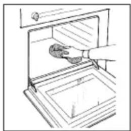
Line drawing of a hand cleaning a kitchen appliance with a cloth (no text or symbols)- For any repairs always contact an authorised Service Centre and ask for original spare parts. Repairs by untrained people will void your warranty on this product.
- Keep packaging out of reach of children at all times.
General Warnings
• Always use oven gloves to remove and replace food in the oven. Ensure that you support the grill pan when removing it from the oven.
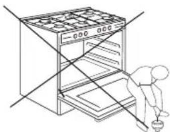
- Don't let children sit down or play with the oven door. Do not use the drop down door as a stool to reach above cabinets.
• DO NOT SPRAY AEROSOLS IN THE VICINITY OF THIS APPLIANCE WHILE IT IS IN OPERATION.
• DO NOT STORE OR USE FLAMMABLE MATERIALS IN THE APPLIANCE STORAGE DRAWER OR NEAR THIS APPLIANCE.
- THIS PRODUCT IS NOT FOR USE IN MARINE CRAFT, CARAVANS OR MOBILE HOMES.
• DO NOT MODIFY THIS APPLIANCE.
natural_image
Line drawing of a person cleaning an oven with a tool, no text or symbols presentWarning:
Never use the food-warmer drawer set at the bottom of the range to store inflammable substances or matters that cannot withstand heat such as: wood, paper, spray cans, rags, etc.
This electric appliance complies with the following directives:
- 2004/108/EEC (electromagnetic compatibility)
- 89/109/EEC (foodstuffs)
- 2006/95/EEC (low voltage)
- 2009/142/CE ex 90/396/CE (gas fittings)
IMPORTANT NOTICE TO THE USER
The base element is concealed beneath the bottom of the oven to make the oven easier to clean and contribute to better access into the oven.
Because the element is concealed beneath the oven the following rules will need to be observed during cooking to ensure optimum performance from the oven.
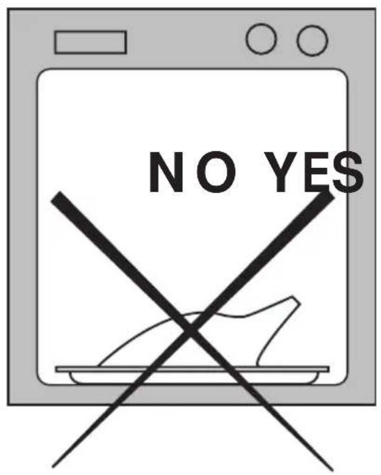
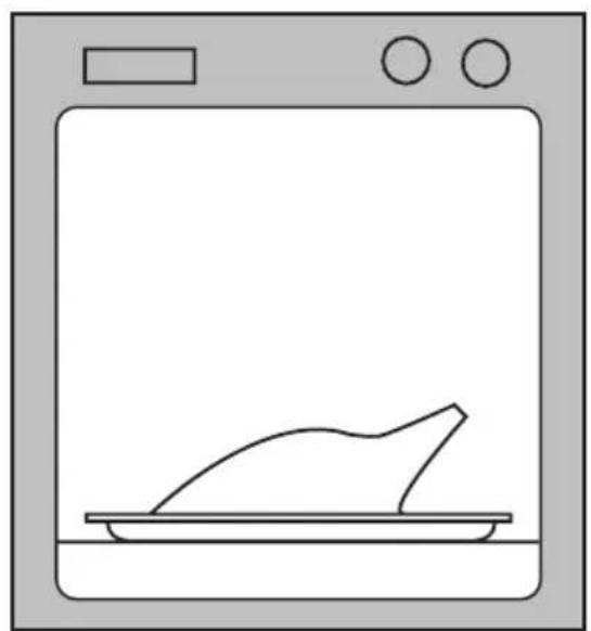
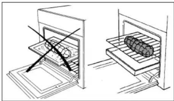
DO NOT PLACE ALUMINIUM FOIL OR METAL OBJECTS ON THE BASE OF THE OVEN DURING COOKING.
Foil or dishes must never be placed on the base of the oven during cooking as the concentration of the direct and reflected heat will damage the enamel surface. Provisions of the warranty do not cover damage resulting from such use.
natural_image
Simple line drawing of a kitchen appliance with a plate and a chicken on top (no text or symbols)Instructions for Installation
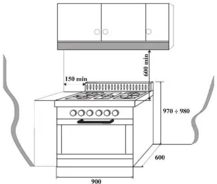
DIMENSIONS AND INSTALLATION FEATURES
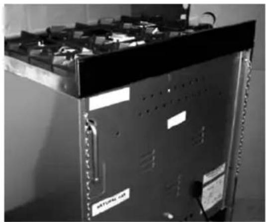
TO FIT THE STABILISING CHAINS
In order to prevent tipping of the appliance it is equipped with 2 chains for stabilising means and must be installed and is required for safety reasons.
After the connection to gas and electrical supply is completed and oven is located in its final position. The following MUST be done:
The 2 chains are fitted in the upper part of the rear right and the rear left side. These two chains enable the cooker to be fixed to the wall
- The anchor used to attach the chains to the rear wall must be of a type suitable for the purpose
- If the appliance is installed between two cupboards, drill a hole big enough on each side of the cupboards, to allow the chains to pass through the holes and anchor the chains within each cupboards
- If the appliance is installed next to drawers, remove the drawers, then carry out the procedure described in point 2. Ensure the anchor does not interfere with the operation of the drawers. If the cooker is to be installed next to an appliance, such as a dishwasher, temporarily remove the appliance for access to fit the stabilising chains.
- Make sure the fixing to the wall is as close as possible to the chain anchor point on the cooker and that the chains are taught to effectively prevent the appliance from tilting.
natural_image
Exterior view of a server rack unit with visible battery and ventilation slots (no text or symbols)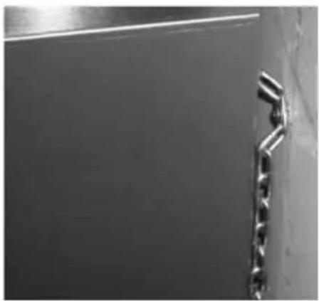
natural_image
Close-up of a metallic bracket with engraved text, no visible modern signage or symbolsImportant: For a unique situation where the stabilising chains cannot be fitted, please contact Blanco Technical Department for advice.
When the oven is moved for servicing – THE CHAINS MUST BE RE-ATTACHED by the Technician.
THE MANUFACTURER DECLINES ANY AND ALL RESPONSIBILITIES FOR DAMAGES TO PROPERTY OR INJURIES TO PERSONS OR ANIMALS DERIVING FROM INCORRECT INSTALLATION OR USE OF THE EQUIPMENT SET OUT IN THE MANUAL.
ELECTRICAL CONNECTION
The appliance is fitted with an Australian approved 15 Amp flexible cord and plug which must be connected to a correctly earthed socket outlet.
The manufacturer is not liable for any direct or indirect damage caused by faulty installation or connection. It is therefore necessary that all installation and connection operations are carried out by qualified personnel complying with the local and general regulations in force.
CONNECTION OF THE FEEDING CABLE TO THE MAINS
Connect the feeding cable to a plug suitable for the load indicated on the rating plate of the product. In case of a direct connection to the mains (cable without plug), it is necessary to insert a suitable omnipolar switch before the appliance, with minimum opening between contacts of 3 mm (the grounding wire should not be interrupted by the switch).
Before connecting to the mains, make sure that:
- The electrical counter, the safety valve, the feeding line and the socket are adequate to withstand the maximum load required (see rating plate).
- The supply system is regularly grounded, according to the regulations in force.
- The socket or the omnipolar switch can easily be reached after the installation of the oven
- After carrying out the connection to the mains, check that the supplying cable does not come into contact with parts subject to heating.
- Never use reductions, shunts, adaptors which can cause overheating or burning.
natural_image
Simple line drawing of a mechanical device with intersecting lines (no text or symbols)The manufacturer is not liable for any direct or indirect damage caused by faulty installation or connection. It is therefore necessary that all installation and connection operations are carried out by qualified personnel complying with the local and general regulations in force.
Electrical features
Oven light 2x25 W
Upper heating element 1100 W
Bottom heating element 1500 W
Grill heating element 2600 W
Circular heating element 2600 W
Instructions for Installation
This appliance shall be installed only by authorised persons and in accordance with the manufacturer's installation instructions, local gas fitting regulations, municipal building codes, electrical wiring regulations, local water supply regulations, AS 5601 - Gas Installations and any other statutory regulations.
Ventilation
Ventilation must be in accordance with AS5601 - Gas Installations. In general, the appliance should have adequate ventilation for complete combustion of gas, proper flueing and to maintain temperature of immediate surroundings within safe limits.
Combustible Surfaces
Any adjoining wall surface situated within 200mm from the edge of any hob burner must be a suitable non-combustible material for a height of 150mm for the entire length of the hob. Any combustible construction above the hotplate must be at least 600mm above the top of the burner and no construction shall be within 450mm above the top of the burner. Zero clearance is permitted on side and rear adjoining surfaces below the hob.
Gas connection
The appliance must be connected to the gas supply or the cylinder according to the specifications of the standards and after checking that it is adjusted for the type of gas available.
The gas connection is male 1/2" BSP and is situated 55mm from the right and 565mm from the floor. There are two ways to carry out the connection to the main gas line:
A. The Cooker can be connected with rigid pipe as specified in AS5601 table 3.1. B. The cooker can be connected with a Flexible Hose, which complies with AS/NZS 1869 (AGA Approved), 10mm ID, class B or D, between 1 - 1.2m long and in accordance with AS5601 for a high level connection. The hose should not be subjected to abrasion, kinking or permanent deformation and should be able to be inspected along its entire length. Unions compatible with the hose fittings must be used and connections tested for gas leaks. The fixed consumer piping outlet should be at approximately the same height as the cooker connection point, pointing downwards and approximately 150mm to the side of the cooker. The hose should be clear of the floor when the cooker is in the installed position. Fix one end of the chain on the screw next to the gas inlet connection and the other end should be anchored to the floor/wall so that the chain prevents strain on the hose connections when he cooker is pulled forward.
The appliance is factory set for Natural gas. The test point pressure should be adjusted to 1.00kPa with the Wok burner operating at maximum.
The appliance is set up to operate with the gas specified on the gas type label placed on the back of the appliance.
When the type of gas available does not correspond to that for which the appliance is set up, replace the corresponding injectors (provided), being careful to put on the new data label (provided) and remove the old one.
To perform these operations the qualified installer will follow the indications given in the "Adaptation to the various types of gas" section. For safer operation make sure that the supply pressure respects the values given in the "Table of burner and injector characteristics".
If installing for use with propane gas, ensure an AGA Approved gas regulator suitable for a supply pressure of 2.75kPa is part of the gas tank supply and the test point pressure is adjusted to 2.75kPa.
Once the appliance has been installed, make sure that the gas pipe is neither squashed or damaged by moving parts.
Before Leaving - Check all connections for gas leaks with soap and water. DO NOT use a naked flame for detecting leaks. Ignite all burners both individually and separately to ensure correct operation of gas valves, burners and ignition. Turn gas taps to low flame position and observe stability of the flame for each burner individually and separately. When satisfied with the operation of the cooker, please instruct the user on the correct method of operation. In case the appliance fails to operate correctly after all checks have been carried out, refer to the authorised service provider in your area.
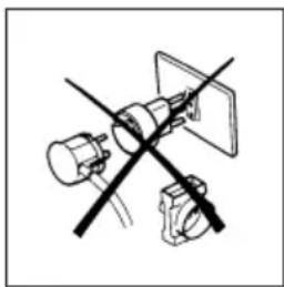
Adaptation to different types of gas
To adapt the appliance to a gas different from that for which it was set up (see gas type label inside the warming compartment door) proceed as follows:
- remove the grids
- remove the burners caps and burner heads
- with a 7 mm socket spanner unscrew and remove the injectors.
- replace the injectors with those supplied corresponding to the gas available (see burner and injector characteristics Table)
- replace the various parts proceeding in reverse.
When converting from Natural Gas to Propane ensure that the NG regulator is removed and replaced with the Test Point
natural_image
Hand holding a knob with a black arrow pointing to the knob area (no text or symbols)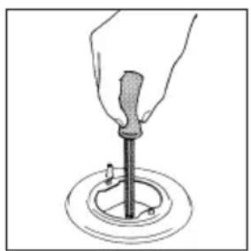
natural_image
Illustration of a hand using a screwdriver to lift a circular component (no text or symbols)Assembly. A gas regulator suitable for a supply pressure of 2.75kPa should be part of the gas tank supply and the test point pressure should be adjusted to 2.75kPa. Replace the old data plate with one that is suitable for the type of gas for which the appliance has been converted.
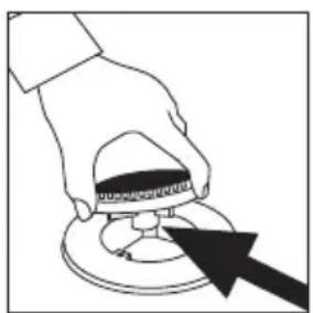
Setting the minimum flame
The flame on the small output is regulated in the factory. When the injectors have been replaced or there are special mains pressure conditions, it may be necessary to regulate the minimum again. The operations necessary to perform this operation are the following:
- light the burner
- turn the knob to the minimum position
• take out the knob (and gasket if there is one) - using a suitably sized screwdriver turn the regulation screw inside or by the side (for safety valve version) of the tap shaft until a small regular flame is obtained
- put the knob back on and turn it quickly from the maximum position to the minimum position, checking that the flame does not go out
- for burners with safety valve make sure that the regulation obtained is sufficient to maintain heating of the thermocouple. If it is not, increase the minimum.
natural_image
Hand holding a tool near a circular object, with two small objects above (no text or symbols)THE BURNERS REQUIRE NO REGULATION OF THE PRIMARY AIR.
Burner and injector characteristic table
| nirc | Burner | By pass mm | Consumption (*) | |||
| Propane | Natural gas | |||||
| Output MJ/h | Main Injector mm | Output MJ/h | Main Injector mm | |||
| 1 | Rapid | 0.44 | 10.8 0.89 | 11.0 1.50 | ||
| 2 | Semi-rapid | 0.34 | 6.3 | 0.68 | 6.9 | 1.16 |
| 3 | Fish / BBQ | 0.55 | 10.8 | 0.89 | 11.0 | 1.50 |
| 4 | Auxiliary | 0.29 | 3.8 | 0.53 | 3.8 | 0.88 |
| 5 | Wok | 0.64 | 12.9 | 1.00 | 15.0 | 1.75 |
| Test point pressure | 2.75 kPa | 1.0 kPa | ||||
(*) = With dry gas and with greater calorific power ( Hs ) at 15°C and 1013.26 mbar
FD9085WX
FD9085FX
FD9085FB
FD9085FR
FD9085FG
FD9085FCR
Instructions for Use
(gas cooktop)
Description of the main parts of the appliance
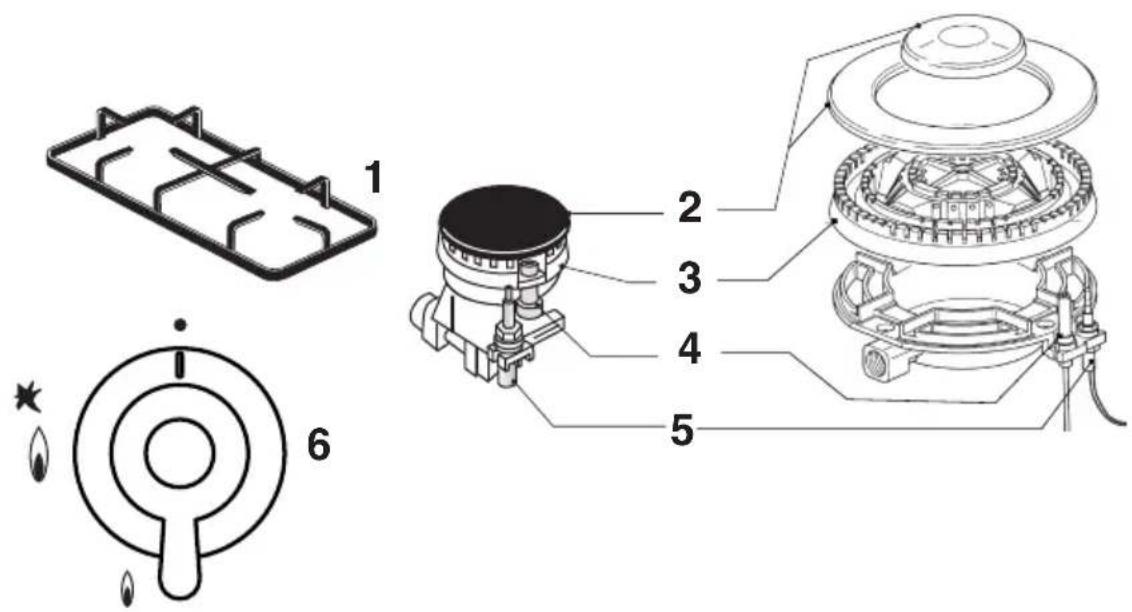
1 = grid
2 = burner cap
3 = burner head
4 = spark plug
5 = safety valve (for models equipped with a safety valve)
6 = knob for burner ignition and adjustment
ABNORMAL OPERATION
ANY OF THE FOLLOWING ARE CONSIDERED TO BE ABNORMAL OPERATION AND MAY REQUIRE SERVICING:
• Yellow tipping of the hob burner flame.
- Sooting up of cooking utensils.
- Burners not igniting properly.
- Burners failing to remain alight.
- Burners extinguished by oven door.
• Gas valves, which are difficult to turn.
IN CASE THE APPLIANCE FAILS TO OPERATE CORRECTLY, CONTACT THE AUTHORISED SERVICE CENTRE IN YOUR AREA.
Instructions for Use
(gas cooktop)
flowchart
graph LR
A["Component 1"] --> B["Component 2"]
B --> C["Component 3"]
C --> D["Component 4"]
D --> E["Component 5"]
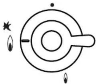
E --> F["Control Panel"]
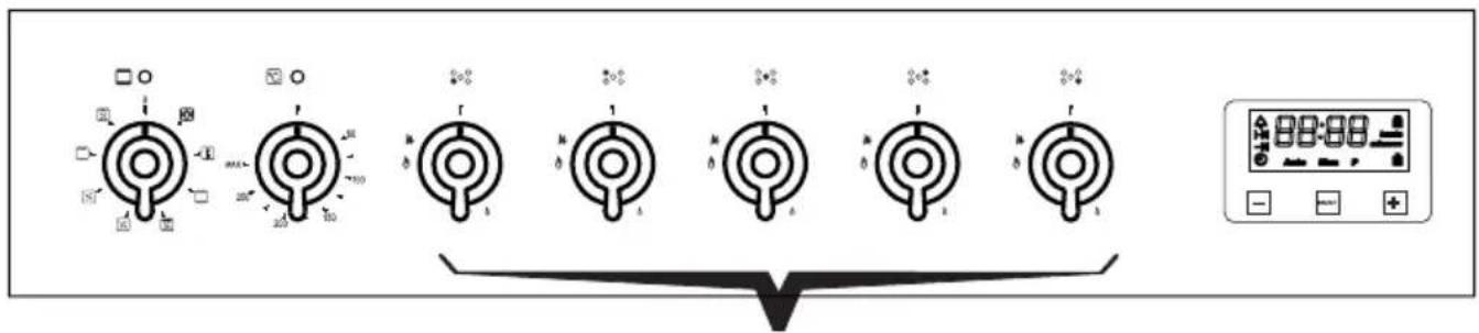
The control panel houses the knobs for operation of the gas burner.
In order to ignite a burner, it is necessary to depress the knob while rotating it anticlockwise, till the index is aligned with the position corresponding to the maximum gas delivery (i.e. the large flame symbol). As far as the models equipped with a safety valve are concerned, once the flame is lit hold the knob depressed for about 3-4 seconds till the device keeps the burner automatically lit. If the burner fails to ignite wait one minute for the gas to dissipate before attempting to reignite. At this moment it is possible to adjust the flame intensity by rotating the knob anticlockwise from such maximum position to the minimum one (i.e. the small flame symbol).
natural_image
Simple line drawing of a target with concentric circles and two flame-like symbols at the bottom (no text or labels)In order to turn the burner off, rotate the knob clockwise bringing the index back to the position corresponding to the closure symbol ( ● ).
RECOMMENDATIONS
In case of electric power failure, it is necessary to carry out the above-described operations by putting a gas lighter or a flame near the burner (in such an event, pay the utmost attention not to burn yourself).
The safety valve (for models where such item is provided) intervenes in case of accidental flame failure, blocking the gas delivery (e.g.: air draughts, spillage of liquids, etc.).
In any case, the ignition device must not be actuated for longer than 15 seconds.
Should the ignition manoeuvre fail, or should the burner be accidentally turned off, immediately close the actuation knob and repeat the ignition after one minute at least.
Once the ignition has taken place, adjust the flame according to your needs.
Instructions for Use
(gas cooktop)
Advice on the use of gas burners
For lower gas consumption and a better yield, use saucepans with diameter suitable for the burners, avoiding the flame coming up round the side of the saucepan (see the Container Table). Use only flat-bottomed pans.
As soon as a liquid starts to boil, turn the flame down to a level sufficient to maintain boiling.
During cooking, when using fats and oils, be very careful because if they overheat they could catch fire.
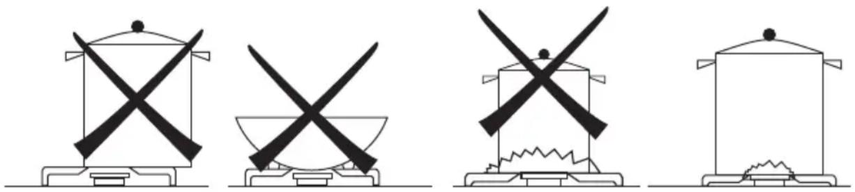
natural_image
Four identical line drawings of a cooking pot with crossed blades, one in a bowl, another in a pot with crossed blades, and one in a pot with a pile of food (no text or symbols)Container table (use flat-bottomed saucepans)
| Burners ø min Saucepan (mm) | ø max Saucepan (mm) |
| Auxiliary 90 160 | |
| Semi - Rapid 130 180 | |
| Fish /BBQ 310 x 140 460 x 230 | |
| Rapid 150 260 | |
| Wok 210 270 |
Instructions for Use
(oven)
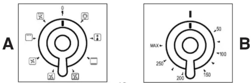
The selector A and thermostat B control is used to select the various oven functions and to choose the cooking temperatures best corresponding to the food to be cooked. During oven operation the lamp will always remain on.

The lamp of the oven is on, with no heating elements operated (electrical resistances). During oven operation the lamp will always remain on.

DEFROST
The oven-fan is operated; by stirring the cold air inside the oven, it aids in quick defrosting of frozen products. No heating elements are operated.

TRADITIONAL
Upper and lower heating elements operated; temperature adjustable from 50irc C to MAX on the thermostat. Suitable for cooking meats, poultry and cakes that require long slow cooking. It is advisable to pre-heat the oven.

FAN ASSIST
Upper and lower heating elements and the oven-fan operated; temperature adjustable from 50°C to MAX on the thermostat. A continuous circulation of warm air is created. Suitable to use when cooking on multiple shelves.

BOTTOM ELEMENT + FAN
Lower heating element and the oven-fan operated; temperature adjustable from 50irc C to MAX on the thermostat.

FAN FORCED
The circular heating element and fan come into operation and the heat is spread evenly to all shelf positions. Various types of food can be cooked on different shelves, naturally with the appropriate cooking times. The oven must be preheated before the foods are placed inside. Fan mode provides optimum results with: most cakes, large quantities of foods and cooking various dishes simultaneously. To operate, select Fan Forced function along with the temperature.

GRILL
Grill Element - Use for toasting and melting cheese or browning. No longer than 5 minutes cooking time. To operate, select Full Grill Function along with the temperature.

FAN GRILL
Grill Element and Fan. Use for grilling meats, vegetables and poultry. Preheat oven, place food on grill rack in baking tray and place in the middle of the oven.
The oven door must be closed for all cooking methods
Instructions for Use
(oven)
COMPONENT OPERATION
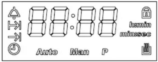
ELECTRONIC PROGRAMMER
Setting the current time
When the electricity has been connected, "12:00" and the symbol 🌐 flash on the display. By touching any of the controls (+, - or SELECT), the symbol MAN appears, and it is possible to adjust the time within 5 seconds by pressing - or +.
The time can be adjusted subsequently by repeatedly touching SELECT until the symbol flashes and then adjusting the time as described above.

General notes
- If the current time is adjusted whilst an automatic programme is active, this will be cancelled.
- It is possible to modify the intensity of the buzzer by repeatedly touching SELECT until the tone set appears (L1, L2 or L3) and pressing + or -.
- If not deactivated the buzzer stops automatically after about 7 minutes.
- The maximum time of programming is 23 hours 59 minutes.
- If there is a power cut, all the programmed settings are cancelled; when the power returns, the display pulses showing 12:00. To restore the functioning mode of the appliance, set the current time again and any programme.
Buzzing timer
To use it as a simple timer, touch SELECT repeatedly until the symbol ⚙ flashes, set the desired time pressing + or -, after about 5 seconds the ⚙ symbol stops flashing and the time starts to decrease; to change the time set or zero it, press + or -.
When the time has run out, to deactivate the buzzer, touch any of the controls.
The maximum time that can be set is 99 minutes.
Setting end of cooking
To start cooking immediately and set how long it lasts, act as follows:
- put the dishes to be cooked in the oven and select the function and temperature desired through the function selector and the thermostat
- touch SELECT repeatedly until the symbol → flashes and set the cooking time within 5 seconds, pressing + or -.
After a few seconds, the current time will reappear and the symbols 📄 and AUTO will remain activated.
The remaining cooking time can be checked by pressing SELECT until the symbol is selected, or modified or zeroed by pressing + or -.
At the end of the cooking time, the buzzer sounds and the oven switches off automatically, the display shows 0.00 and the symbol MAN flashes. To deactivate the buzzer, press any of the controls; touch SELECT for manual programming again, the symbol MAN stops flashing and the oven can be used again.
Instructions for Use
(oven)
Setting start and end of cooking time
To programme both the starting and ending of the cooking time:
- touch SELECT until the symbol → appears, set the cooking time pressing + or - within 5 seconds;
- touch SELECT again until the symbol → is selected to set the end of the cooking time.
- put the dishes to be cooked in the oven and select the function and temperature desired using the function selector and the thermostat.
The start of cooking will be given from the time of the end of cooking minus the duration of the cooking. 5 seconds after releasing the controls, the current time will reappear and the symbol AUTO will remain activated and so will the symbol 📋 at the start of the cooking time.
When the cooking time is completed, the buzzer sounds and the oven switches off automatically. To deactivate the buzzer, press any of the controls; touch SELECT to make the programmer manual again, the symbol MAN stops flashing and the oven can be used again.
To cancel the programming, zero the cooking time.
Safety lock
This electronic programmer has a function which locks the oven and the programming set.
The lock does not work with the timer active.
Activation: touch the control + for about 5 seconds then the symbol 🔒 appears.
Notes:
- if the lock is activated with the display showing the current time and no programming is set (end of cooking or start and end of cooking), the oven is locked.
- if it is activated with the oven working or a programming selected (end of cooking time or start and end of cooking), the lock prevents modifying the programmes.
Deactivation: touch + for about 5 seconds.
NOTE: if there is a power cut, when the power returns the lock will still be active.
PILOT LIGHT OF THE THERMOSTAT


It comes on any time the thermostat settles the cooking temperature inside the oven and it is switched off when the oven reaches the preset temperature.
It signals that the appliance is powered and stays on in all working positions.
Instructions for Use
(oven)
SAFETY THERMOSTAT
It cuts out the electric supply for preventing possible overheatings when the appliance is not correctly used. In this case, wait for the oven to cool down before using it again. On the other hand, if a fault is present on the appliance's components, we advise calling the Technical Assistance Service.
COOLING MOTOR
The equipment comes with a motor for cooling the inside elements. This motor starts automatically when using the oven.
Instructions for Cooking
It is necessary to pre-heat the oven to the preset cooking temperature. Only very fat meat can be placed into a cold oven. To minimise food splashes into the oven (which can sometimes produce smoke) deep baking dishes are recommended.
Practical hints to save energy
The oven can be switched off some minutes before the end of cooking. The residual temperature is enough to complete
natural_image
Two technical line drawings showing a kitchen setup with a tray, a stove, and a rack of food items (no text or symbols present)cooking. Open the oven door only when it is absolutely necessary. To check the cooking progress, look through the glass (the oven lamp is always on).
General Advice
The oven offers various kinds of heating:
• Traditional heating for the cooking of special roasts that require slow cooking.
• Fan forced - for cooking cakes, biscuits and similar.
- If the fan forced cooking is chosen, you can put your roast meat (as an example) on various shelf positions. You can also cook multiple dishes in the oven at the same time to help save energy.
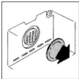
OVEN WITH PROTECTION FILTER OF THE FAN
During the cooking of fatty products, to avoid too much fat residue striking the fan, the filter should be placed in the oven before use. When cooking is finished and oven cools, remove the filter and wash it carefully. Install the filter by leaning it against the rear wall at the same level of the fan, then push the tang downwards. Reverse this operation to remove the filter.
ATTENTION:
The filter should be only used when cooking fatty foods. Better cooking results for non fatty foods will be achieved without the filler installed.
natural_image
Diagram of a microwave oven with a circular vent and a circular cover, showing airflow direction (no text or symbols)COOKING TIMES
- The times indicated in the table refer to the cooking of one food only. For more than one food, the cooking times should be increased by 5 - 10 minutes.
For beef, veal, pork and turkey roasts with bones or rolled, add about 20 minutes to the times shown in the table.
TABLE OF COOKING TIMES
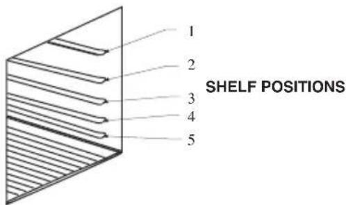
The table below provides indicative shelf positions for use with your oven. Please note, the temperature and cooking times are indicative only. According to different cooking habits, it may be necessary to make further modifications. Add to the below-mentioned times about 15 minutes for preheating.
| Shelf position Temperature (°C) | Time (Mins) | ||
| Fan oven Fan oven | |||
| SweetsPastry 2 (3/4/5) 200-230 20-30Sponge cakes 2 (2/3/4/5) 185-200 35-45 | |||
| FishFillets or slices 2 (2/3/4) 180-200 15-20 | |||
| MeatVeal 2 (2/3/4/5) 175-190 60-70Pork 2 (2/3/4/5) 175-200 70-90Chicken 2 (2/3/4/5) 175-200 80-90Turkey 2 (2/3/4/5) 175-200 90-120Beef 2 (2/3/4/5) 175-200 70-90Lamb 2 (2/3/4/5) 180-200 85-100 | |||
| Bread and pizzaPizzaMuffinsBread | 2 (2/3/4)2 (2/3/4/5)3 (2/3/4/5) | 200-230175180-200 | 15-2520-3040-50 |
| BakesVegetable bake | 2 (2/3/4) | 175-185 | 30-40 |
FAN OVEN

Instructions for the assembly of bottom kick plate onto the cookers
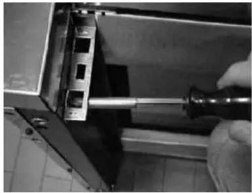
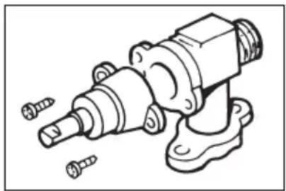
Screw both brackets (provided with the relevant spring) to the inner part of the cooker side (by utilizing the kit of screws) respectively on the right and on the left, as it is shown in the picture.
natural_image
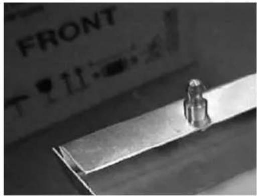
Close-up of a hand using a tool to adjust or install a metal bracket component (no visible text or symbols)Place the kick plate to the cooker, making sure that the pivots of the kick plate coincide with the springs on the bracket.
natural_image
Close-up of a metallic object with a small protrusion, next to a labeled 'FRONT' board (no readable text on the object itself)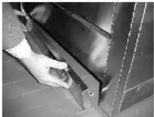
natural_image
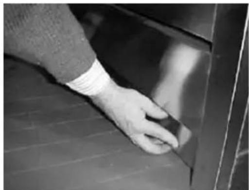
Close-up of a hand opening a metal door, no visible text or symbolsPush back deeply the kick plate, thus fastening it to the cooker structure.
natural_image
Close-up of a hand cleaning a dark surface with a small object on the edge (no text or symbols visible)Maintenance and Cleaning
Do not use jet of steam for cleaning.
Before any operation disconnect the appliance electrically. Wash the enamelled parts with lukewarm water and detergent. Do not use abrasive products.
Wash the burner spreader frequently with boiling water and detergent being sure to remove any deposits which could block the flame outlet. Rinse the stainless steel parts well with water and dry them with a soft cloth.
To clean the hob use slightly damp sponges and wiping cloths: if too much water is used it could penetrate the internal parts and damage electrical parts.
The grids of the hob can be washed in the dishwasher.
For persistent stains use normal non-abrasive detergents, specific products commonly available on the market or a little hot vinegar. Clean the glass parts with hot water, avoiding the use of rough cloths.
Do not use stainless steel pads or acids for cleaning.
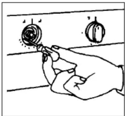
To prevent lighting difficulties, carefully clean the lighting spark plugs regularly (ceramic and electrode).
Periodically, or if the knobs become difficult to turn, contact a qualified engineer to lubricate the taps.
Contact a qualified engineer to deal with any other problems which may arise during use.
natural_image
Technical line drawing of a mechanical assembly with screws and housing (no text or symbols)To keep the characteristics of brightness of the enamelled parts for a long time it is necessary to clean the oven after each cooking. Once the oven is cold, you will be able to easily remove the fat deposits by means of a sponge or a cloth damp with warm soapy water and eventually a detergent to be found on the market. Never use abrasive cloths or sponges, that could irreparably damage the enamel. On white ovens even the parts of the dash board such as handgrip and knob have to be cleaned each time because they may become yellow due to the emissions of fat vapours.
ALWAYS CLEAN THE APPLIANCE IMMEDIATELY AFTER ANY FOOD SPILLAGE.
TO MAINTAIN SAFE OPERATION, IT IS RECOMMENDED THAT THE PRODUCT BE INSPECTED EVERY FIVE YEARS BY AN AUTHORISED SERVICE PERSON.
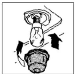
Replacing the oven bulb
Once the oven has been electrically disconnected, unscrew the glass protection cap and the bulb, replacing it with another one suitable for high temperatures (300°C / E14). Reassemble the glass cap and reconnect the oven.
natural_image
Diagram showing a hand holding a light bulb above a head, with arrows indicating motion or force direction (no text or symbols)Maintenance and Cleaning
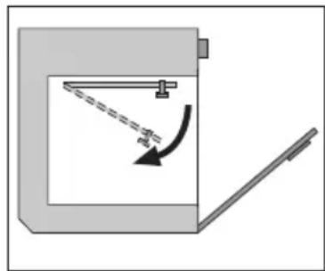
Ovens with facility to lower grill for cleaning purposes
1 Warning: ensure that all controls are in the "OFF" position and wait for the grill element to be cool.
2 Support the front of the grill element while you remove the knurled screw retaining the element.
3 Lower the front of the element carefully to the rest position.
4 When cleaning the oven take care to not apply any forces to the grill element
5 When the cleaning is complete, carefully remove any cleaning chemicals and water from the grill element.
6 Carefully raise the front of the element into position and secure with the knur-led screw.
natural_image
Simple diagram of a mechanical device with a lever and curved arrow indicating motion (no text or symbols)NEVER USE THE OVEN WITH THE GRILL ELEMENT HANGING DOWN!
Important. In case of burners removal for cleaning purposes, we recommend to make sure that all parts are correctly positioned before igniting the burners again.
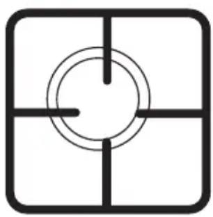
THE GRIDS OF THE COOKING PLANE ARE EQUIPPED WITH SUITABLE RUBBER PADS, WHOSE PURPOSE IS BOTH PROVIDING BETTER STABILITY AND AVOIDING SCRATCHES ON THE PLANE SURFACES DURING USAGE.
AFTER A POSSIBLE GRID REMOVAL FOR CLEANING AND/OR MAINTENANCE NEEDS, WE RECOMMEND TO VERIFY THE PRESENCE OF SUCH RUBBER PADS AND TO PUT THE GRIDS BACK IN THEIR STABLE AND CENTRED CORRECT POSITION.
natural_image
Simple geometric diagram with concentric circles and intersecting lines inside a square frame (no text or symbols)NO

natural_image
Simple geometric diagram with concentric circles and intersecting lines inside a square (no text or symbols)YEIS
Maintenance and Cleaning
Cleaning the oven door
ATTENTION: for your safety, before removing any glass section you should firstly remove the oven door.
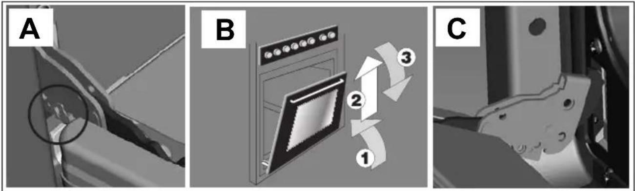
Dismounting the door
- Open the oven door completely
- Lift up the U-bolts in the lower part of the hinges (fig. A). This way the springs of the hinges are blocked. By closing the door, following the sequence 1, 2 and 3 of figure B, it can be removed from the oven (fig.C).
To remount the door, proceed with the operations described in reverse order.
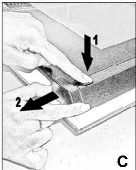
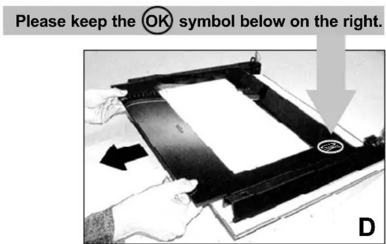
Disassembling of the door glasses
To facilitate the cleaning, after having removed the door from the oven, you can proceed with the disassembly of the glass. Release the two upper blocks (picture C) so that the glass can be removed (picture D). After the cleaning you should reassemble the glass, replace the blocks and lock into position. Check that all components have been assembled correctly and than you can re-assemble the door onto the oven.
BLANCO CUSTOMER SERVICE 1300 739 033
www.meaappliances.com.au
SALES OFFICES AND SHOWROOMS
SERVICE AND SPARE PARTS
NEW SOUTH WALES. QUEENSLAND.
Head Office, Sales and Marketing Brisbane.
104 Vanessa Street. Endeavour Refrigeration and Appliance Service.
Kingsgrove. Telephone: 07 3137 3633
NSW 2208. Facsimile: 07 3137 3663
Telephone: 02 9503 2888 www.endeavourservice.com.au
Facsimile: 02 9503 2810
Gold Coast.
Sydney Showroom.
Roshad Appliance Service.
40 Ebley Street. Telephone: 07 5535 7044
Bondi Junction. Facsimile: 07 5535 7407
NSW 2022
Telephone: 02 9386 1190 Sunshine Coast.
Facsimile: 02 9386 1671 Paul Matters Electrical.
Telephone: 07 5449 7133
Facsimile: 07 5449 9045
QUEENSLAND
Brisbane Showroom.
148 Robinson Road East.
Geebung.
QLD 4034.
Telephone: 07 3259 2555
Facsimile: 07 3265 6933
NEW SOUTH WALES.
All General Whitegoods.
Telephone: 02 8788 8666
Facsimile: 02 9752 5294
www.agw.com.au
VICTORIA.
Melbourne Showroom.
35 Centre Road.
Scoresby.
VIC 3179
Telephone: 03 8756 7888
Facsimile: 03 8756 7907 VICTORIA.
AUSTRALIAN CAPATIAL TERRITORY
Detlevs Appliance & Electrical Care
Telephone: 02 6260 1033
Facsimile: 02 6260 1035
South Australia Showroom (By Appointment only)
SC Lighting & Electrical Supplies
47 North Terrace
Hackney Facsimile: 03 9874 6917
SA 5069
Telephone: 08 8362 4599
Facsimile: 08 8362 4591
Advantage Appliance Service
Telephone: 03 9874 4222
Western Australia Sales Office
2A/1 King Edward Road,
Osborne Park,
WA 6017
Telephone: 08 9446 5299
Facsimile: 08 9204 1219
SOUTH AUSTRALIA
Prestige Appliance
Telephone: 08 8352 2022
Facsimile; 08 8352 2044
www.prestigerepairs.com.au
*SHOWROOMS ARE OPEN 6 DAYS A WEEK.
WESTERN AUSTRALIA
Metropolitan Appliance Service
Telephone: 08 9330 1724
Facsimile: 08 9317 1296
STATEMENT OF STANDARD WARRANTY CONDITIONS
-
The Warranty only applies provided that the appliance has been used in accordance with the manufacturer's instructions and provided that the appliance has not been damaged by an accident, misuse, neglect or abuse of any person other than the manufacturer or BLANCO/Major Electrical Appliances ("MEA") or from faulty installation, misadjustment or tampering by unauthorised persons.
-
When a service inspection reveals the alleged fault or faults are caused by incorrect operation, contrary to the instruction manual, and otherwise the appliance is in good order and working condition, the purchaser shall be liable for a service fee charged by BLANCO/MEA or one of its' Service Providers.
-
If the appliance is used in Commercial Applications or for Rental purposes, a separate warranty of Twelve (12) months covering all parts with Three (3) months on the labour will apply.
-
Subject to the provisions of any applicable statute this Warranty applies to the original retail purchaser only and is not transferable.
-
Subject to the provisions of any applicable statute, at no time does BLANCO/MEA have liability for freight. transport or travel costs outside normal service areas.
-
None of the above Warranties purport to exclude, restrict or modify either the application or the exercise of a right conferred by any applicable statute.
-
Subject to any Warranties implied by statute, at no time will BLANCO/MEA or its Service Providers be liable for any economic loss consequent upon the failure of the appliance
-
This Warranty is only valid for major appliances imported and distributed by BLANCO/MEA, purchased and used in Australia.
BLANCO COOKING PRODUCT WARRANTY
- Subject to the "Statement of Standard Warranty Conditions" this product is covered by the following Warranty.
TWO (2) YEARS WARRANTY from date of purchase, covering all parts and labour.
-
The appliance is warranted under normal single family domestic installation and use, as set out in the instruction manual, against manufacturing defects for the Warranty periods shown above.
-
Should service be required under this Warranty, the purchaser should contact an approved BLANCO Service Provider during their normal business hours
-
At no time does BLANCO/MEA have liability for any freight or transportation costs or for any damage during transit or for any consequence of failure of this appliance outside of the normal service area, unless such limitation of liability is prohibited by statute.
-
This Warranty excludes replacement of parts required due to normal wear and tear including light globes.
-
This Warranty only applies, provided the appliance has been used in accordance with the manufacturer's instructions and provided an accident, misuse, neglect or abuse has not damaged the appliance.
-
None of the above Warranties purport to exclude, restrict or modify either the application or the exercise of a right conferred by any applicable Statute.
-
Please complete the details below, which should be retained for future reference along with your proof of purchase
Date of Purchase:......
Model No:......
Serial No: ....
Rating plate of the product
Dis. S506_998 -I/C-
Cod. 099241009940
Rev. 1 del 11/10
- Dear Customer
- BLANCO
- Index
- GENERAL WARNINGS p. 5 - 8
- Instructions for installation:
- Instructions for use
- Instructions for cooking
- Instructions for the assembly of bottom kick plate onto the cookers
- Maintenance and cleaning
- General Warnings
- Warning:
- IMPORTANT NOTICE TO THE USER
- Instructions for Installation
- DIMENSIONS AND INSTALLATION FEATURES
- TO FIT THE STABILISING CHAINS
- ELECTRICAL CONNECTION
- CONNECTION OF THE FEEDING CABLE TO THE MAINS
- Electrical features
- Ventilation
- Combustible Surfaces
- Gas connection
- Adaptation to different types of gas
- Setting the minimum flame
- (gas cooktop)
- ABNORMAL OPERATION
- RECOMMENDATIONS
- Advice on the use of gas burners
- (oven)
- DEFROST
- TRADITIONAL
- FAN ASSIST
- BOTTOM ELEMENT + FAN
- FAN FORCED
- GRILL
- FAN GRILL
- COMPONENT OPERATION
- ELECTRONIC PROGRAMMER
- Setting the current time
- General notes
- Buzzing timer
- Setting end of cooking
- Setting start and end of cooking time
- Safety lock
- Notes:
- PILOT LIGHT OF THE THERMOSTAT
- SAFETY THERMOSTAT
- COOLING MOTOR
- Practical hints to save energy
- General Advice
- OVEN WITH PROTECTION FILTER OF THE FAN
- ATTENTION:
- COOKING TIMES
- TABLE OF COOKING TIMES
- Do not use jet of steam for cleaning.
- Replacing the oven bulb
- Ovens with facility to lower grill for cleaning purposes
- NEVER USE THE OVEN WITH THE GRILL ELEMENT HANGING DOWN!
- Cleaning the oven door
- Dismounting the door
- Disassembling of the door glasses
- BLANCO CUSTOMER SERVICE 1300 739 033
- SALES OFFICES AND SHOWROOMS
- SERVICE AND SPARE PARTS
- NEW SOUTH WALES. QUEENSLAND.
- Gold Coast.
- QUEENSLAND
- NEW SOUTH WALES.
- VICTORIA.
- AUSTRALIAN CAPATIAL TERRITORY
- SOUTH AUSTRALIA
- WESTERN AUSTRALIA
- STATEMENT OF STANDARD WARRANTY CONDITIONS
- BLANCO COOKING PRODUCT WARRANTY
- TWO (2) YEARS WARRANTY from date of purchase, covering all parts and labour.
Brand : BLANCO
Model : FD9085FR
Category : Cooker