VS-60719 - Television MITSUBISHI - Free user manual and instructions
Find the device manual for free VS-60719 MITSUBISHI in PDF.

User questions about VS-60719 MITSUBISHI
0 question about this device. Answer the ones you know or ask your own.
Ask a new question about this device
Download the instructions for your Television in PDF format for free! Find your manual VS-60719 - MITSUBISHI and take your electronic device back in hand. On this page are published all the documents necessary for the use of your device. VS-60719 by MITSUBISHI.
USER MANUAL VS-60719 MITSUBISHI
natural_image
Black-and-white interior photo of a modern living room with white armchairs, a large TV, and decorative vases (no visible text or symbols)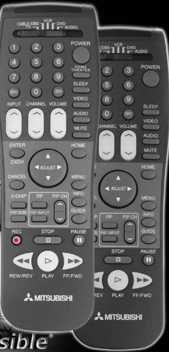
Technically Anything is Possible®
visit our website at
www.w.mitsubishi-t-v.com
CAUTION
RISK OF ELECTRIC SHOCK DO NOT OPEN

CAUTION : TO REDUCE THE RISK OF ELEC- TRIC SHOCK,
DO NOT REMOVE COVER (OR BACK).
NO USER SERVICEABLE
PARTS INSIDE.
REFER SERVICING TO QUALIFIED SERVICE PERSONNEL
The lightning flash with arrowhead symbol within an equilateral triangle is intended to alert the user of the presence of uninsulated “dangerous voltage” within the product’s enclosure that may be sufficient magnitude to constitute a risk of electric shock.

The exclamation point within an equilateral triangle is intended to alert the user to the presence of important operating and maintenance (servicing) instructions in the literature accompanying the appliance.
Warning: To avoid permanently imprinting a fixed image onto your TV screen, please do not display the same stationary images on the screen for more that 15% of your total TV viewing in one week. Examples of stationary images are letterbox top/bottom bars from DVD disk or other video sources, side bars when showing standard TV pictures on widescreen TV's, stock market reports, video game patterns, station logos, web sites or stationary computer images. Such patterns can unevenly age the picture tubes causing permanent damage to the TV. Please see pages 21 and 52 for a detailed explanation.
Note: This equipment has been tested and found to comply with the limits for a Class B digital device, pursuant to part 15 of the FCC Rules. These limits are designed to provide reasonable protection against harmful interference in a residential installation. This equipment generates, uses and can radiate radio frequency energy and, if not installed and used in accordance with the instructions, may cause harmful interference to radio communications. However, there is no guarantee that interference will not occur in a particular installation. If this equipment does cause harmful interference to radio or television reception, which can be determined by turning the equipment off and on, the user is encouraged to try to correct the interference by one or more of the following measures:
- Reorient or relocate the receiving antenna.
- Increase the separation between the equipment and the receiver.
- Connect the equipment into an outlet on a circuit different from that to which the receiver is connected.
- Consult the dealer or an experienced radio/TV technician for help.
Changes or modifications not expressly approved by Mitsubishi could void the user's authority to operate this equipment.
WARNING:
TO REDUCE THE RISK OF FIRE OR ELECTRIC SHOCK, DO NOT EXPOSE THIS APPLIANCE TO RAIN OR MOISTURE.
CAUTION:
TO PREVENT ELECTRIC SHOCK, MATCH WIDE BLADE OF PLUG TO WIDE SLOT, FULLY INSERT.
NOTE TO CATV SYSTEM INSTALLER:
THIS REMINDER IS PROVIDED TO CALL THE CATV SYSTEM INSTALLER'S ATTENTION TO ARTICLE 820-40 OF THE NEC THAT PROVIDES GUIDELINES FOR THE PROPER GROUNDING AND, IN PARTICULAR, SPECIFIES THAT THE CABLE GROUND SHALL BE CONNECTED TO THE GROUNDING SYSTEM OF THE BUILDING, AS CLOSE TO THE POINT OF CABLE ENTRY AS PRACTICAL.
IMPORTANT SAFEGUARDS 4-5
THANOKU
Thank You Letter....8
Unpacking Your New TV....9
Features 9
INSTALLATION
Front Control Panel Functions 12
Back Panel Functions....13
ow Connections Affect:
PIP 14
System 4 Home Theater IR Control....14-15
connecting to Your New Mitsubishi Bigscreen:
Antenna or Wall Outlet Cable 16
Cable Box....16
VCR 17
Audio Receiver....18
DVD Player....19
S-Video Device 19
System 4 Home Theater IR Control....20
IMPORTANT NOTES ......21
SETUP
Programming the Remote Control: To Control Other A/V Products.... 24-25
Programming the Remote Control: To Activate the System 4 Home Theater IR Control ...... 26-27
▶ViewPoint® on-screen menu system ....28
Menu Screens (Overview) 39-30
Setup Menu....31
Memorize Channels 31
Clock....31
Language 31
Captions Menu 32
V-Chip Parent Lock Menu 33-35
Channel Edit Menu....35
Advanced Features Menu 37
Timer....37
Convergence....38
Advanced Convergence 39
Special Features....39
Audio/Video Serrings Menu 40-41
A/V Setting Descriptions 42-43
OPERATION
Remote Control Functions 46-51
Overview 46
Care and Operation 47
Channel Selection....48
Sleep Timer....48
System 4 Home Theater IR Control....48-49
Special Functions ....50
Operation of PIP and POP 51
IMPORTANT NOTES ....52
Appendix A: Bypassing the V-Chip Lock....55
Appendix B: High Resolution Input Connection Compatibility ....57
Appendix C: Remote Control Programming Codes ....58
Appendix D: Cleaning and Service ....59
Appendix E: Troubleshooting....60
Index 61-62
Mitsubishi Projection TV Limited Warranty 63
IMPORTANT SAFEGUARDS
Please read the following safeguards for your TV and retain for future reference.
Always follow all warnings and instructions marked on the television.
1. Read, Retain and Follow All Instructions
Read all safety and operating instructions before operating the TV. Retain the safety and operating instructions for future reference. Follow all operating and use instructions.
2. Heed Warnings
Adhere to all warnings on the appliance and in the operating instructions.
3. Cleaning
Unplug the TV from the wall outlet before cleaning. Do not use liquid, abrasive, or aerosol cleaners. Cleaners can permanently damage the cabinet and screen. Use a lightly dampened cloth for cleaning.
4. Attachments and Equipment
Never add any attachments and/or equipment without approval of the manufacturer as such additions may result in the risk of fire, electric shock or other personal injury.
5. Water and Moisture
Do not use the TV where contact with or immersion in water is possible. Do not use near bath tubs, wash bowls, kitchen sinks, laundry tubs, swimming pools, etc.
6. Accessories

natural_image
Silhouette of a person climbing a ladder inside a circular frame (no text or symbols)Do not place the TV on an unstable cart, stand, tripod, or table. The TV may fall, causing serious injury to a child or adult and serious damage to the TV. Use only with a cart, stand, tripod, bracket, or table recommended by the manufacturer, or sold with the TV. Any mounting of the TV should follow the manufacturer's instructions, and should use mounting accessories recommended by the manufacturer.
An appliance and cart combination should be moved with care. Quick stops, excessive force, and uneven surfaces may cause the appliance and cart combination to overturn.
7. Ventilation
Slots and openings in the cabinet are provided for ventilation and to ensure reliable operation of the TV and to protect it from overheating. Do not block these openings or allow them to be obstructed by placing the TV on a bed, sofa, rug, or other similar surface. Nor should it be placed over a radiator or heat register. If the TV is to be placed in a rack or bookcase, ensure that there is adequate ventilation and that the manufacturer's instructions have been adhered to.
8. Power Source
This TV should be operated only from the type of power source indicated on the marking label. If you are not sure of the type of power supplied to your home, consult your appliance dealer or local power company.
9. Grounding or Polarization
This TV is equipped with a polarized alternating current line plug having one blade wider than the other. This plug will fit into the power outlet only one way. If you are unable to insert the plug fully into the outlet, try reversing the plug. If the plug should still fail to fit, contact your electrician to replace your obsolete outlet. Do not defeat the safety purpose of the polarized plug.
10. Power-Cord Protection
Power-supply cords should be routed so that they are not likely to be walked on or pinched by items placed upon or against them, paying particular attention to cords at plugs, convenience receptacles, and the point where they exit from the TV.
11. Lightning
For added protection for this TV during a lightning storm, or when it is left unattended and unused for long periods of time, unplug it from the wall outlet and disconnect the antenna or cable system. This will prevent damage to the TV due to lightning and power-line surges.
IMPORTANT SAFEGUARDS Continued

12. Power Lines
An outside antenna system should not be located in the vicinity of overhead power lines or other electric light or power circuits, or where it can fall into such power lines or circuits. When installing an outside antenna system, extreme care should be taken to keep from touching such power lines or circuits as contact with them might be fatal.
13. Overloading
Do not overload wall outlets and extension cords as this can result in a risk of fire or electric shock.
14. Object and Liquid Entry
Never push objects of any kind into this TV through openings as they may touch dangerous voltage points or short-out parts that could result in fire or electric shock. Never spill liquid of any kind on or into the TV.
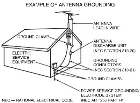
15. Outdoor Antenna Grounding
If an outside antenna or cable system is connected to the TV, be sure the antenna or cable system is grounded so as to provide some protection against voltage surges and built-up static charges.
Section 810 of the National Electric Code, ANSI/NFPA No. 70-1984, provides information with respect to proper grounding of the mast and supporting structure, grounding of the lead in wire to an antenna discharge unit, size of grounding conductors, location of antenna discharge unit, connection to grounding electrodes, and requirements for the grounding electrode.
16. Servicing
Do not attempt to service this TV yourself as opening or removing covers may expose you to dangerous voltage or other hazards. Refer all servicing to qualified service personnel.
17. Damage Requiring Service
Unplug the TV from the wall outlet and refer servicing to qualified service personnel under the following conditions:
(a) When the power-supply cord or plug is damaged.
(b) If liquid has been spilled, or objects have fallen into the TV.
(c) If the TV has been exposed to rain or water.
(d) If the TV does not operate normally by following the operating instructions, adjust only those controls that are covered by the operating instructions as an improper adjustment of other controls may result in damage and will often require extensive work by a qualified technician to restore the TV to its normal operation.
(e) If the TV has been dropped or the cabinet has been damaged.
(f) When the TV exhibits a distinct change in performance - this indicates a need for service.
18. Replacement Parts
When replacement parts are required, be sure the service technician has used replacement parts specified by the manufacturer or have the same characteristics as the original part. Unauthorized substitutions may result in fire, electric shock or other hazards.
19. Safety Check
Upon completion of any service or repair to the TV, ask the service technician to perform safety checks to determine that the TV is in safe operating condition.
20. Heat
The product should be situated away from heat sources such as radiators, heat registers, stoves, or other products (including amplifiers) that produce heat.

As an ENERGY STAR partner, Mitsubishi Digital Electronics America, Inc. has determined that this product meets the ENERGY STAR guidelines for energy efficiency. This product can save energy. Saving energy reduces air pollution and lowers utility bills.
If you have questions regarding your television, call
Consumer Relations
at (800) 332-2119, or email us at
MDEA ser vice@bigscreen.mea.com.com
To order replacement or additional remote controls or owner's guides
call (800) 553-7278
or
visit our website at www.mitsubishi-ty.com

natural_image
Abstract geometric shapes with gradient shading against black background (no text or symbols)Part I

natural_image
Abstract geometric arrangement of three gray parallelograms forming a T-shape (no text or symbols)
natural_image
Abstract geometric shapes with gradient shading and shadows on black background (no text or symbols)Thank You
Thank You Letter 8
Unpacking Your New TV ......9
Features......9

A Note of Thanks from Mitsubishi...
Thank you for choosing Mitsubishi as your premier home entertainment partner. The development team at Mitsubishi understands that our customers are not the average people: they demand and expect the very best. Hence, countless hours have been invested to produce a sophisticated product that we hope will meet all of your expectations.
Whether this is your first Mitsubishi consumer electronic product or simply an addition to your growing Mitsubishi family, we hope that this television will bring you and your family many hours of joy. We are delighted that you chose such a technically advanced product. We know you will not be disappointed.
Unpacking Your New TV
Please take a moment to review the following list of items to ensure that you have received everything included:
1 Remote Control
2 (2) AAA Batteries
4 Product Registration Card
→ Owner's Guide
Quick Reference Card
3 (2) IR Emitter Cables (VS-60719 and VS-70709 ONLY)
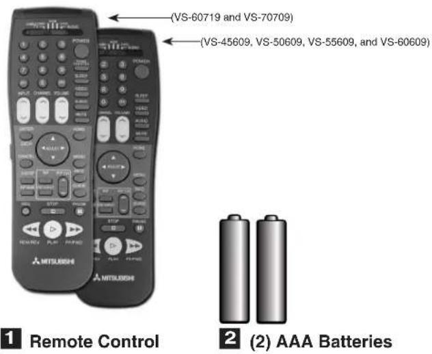
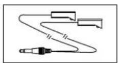
(VS-60719 and VS-70709 ONLY)
3 (2) IR Emitter Cables

Product Registration Card
Features
Your new bigscreen television has many features that make it the perfect addition to your home entertainment system. Below we have highlighted a handful.

System 4 Home Theater IR Control
VS-60719 & VS-70709
This special feature makes it easier to use your TV with a digital surround sound A/V receiver.
See pages 20 & 48-49.
PIP Viewing Option
Using Picture-in-Picture will give you exciting options for viewing your favorite programs. See pages 50-51.
V-Chip Technology
Mitsubishi understands that you may want to shield certain viewers from specific program content. Your Mitsubishi bigscreen will allow you to restrict Programming by general contents, specific contents, or even by time. See pages 33-35.
Multibrand Remote Control
Your Mitsubishi remote control can be programmed to control many other audio/video components.
See page 24-25.
Diamond Shield™
Your Mitsubishi TV is custom fitted with a Diamond Shield that adds a protective shield to the TV screen and enhances the picture quality.
Unlike typical television manufacturers, we have based our primary design and engineering capabilities in North America at our California headquarters. As a result, the engineers who design our television products live in the same communities as our customers. They know how our customers think and what their goals and desires are. They know that today's consumer has never been more sophisticated and that the way to reach that consumer is to deliver technically advanced products at prices that our competition simply can't match.

natural_image
Abstract geometric shapes with gradient shading against black background (no text or symbols)Part II


natural_image
Abstract geometric shapes with gradient shading and white highlights against black background (no text or symbols)Installation
Front Control Panel Functions .....12
Back Panel Functions .....13
How Connections Affect:
PIP 14
System 4 Home Theater
IR Control VS-60719 & VS-70709 14-15
Connecting to Your New Mitsubishi
Bigscreen:
Antenna or Wall Outlet Cable ...16
Cable Box 16
VCR 17
Audio Receiver....18
DVD Player....19
S-Video Device....19
System 4 Home Theater
IR Control VS-60719 & VS-70709 20
IMPORTANT NOTES ......21

Front Control Panel
Many remote control buttons are duplicated on the front control panel. These buttons are shaded in figures 1 and 2. Please see Remote Control Functions, pages 46-51, for an explanation of their functions. You may temporarily deactivate the buttons on the front control panel with the Front Button Lock feature, see Front Button Lock, page 39.
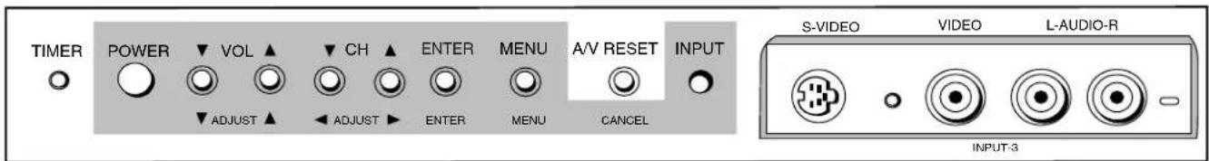
Figure 1. Front Control Panel for models VS-45609, VS-50609, VS-55609, and VS-60719.
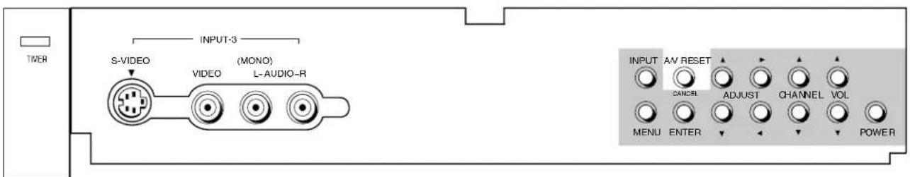
Figure 2. Front Control Panel for model VS-70709.
TIMER or Timer Timer
During normal operation, when the TV is set to turn on at a specific time, the green timer light will blink while the TV is off. Please see Timer, page 37, for timer setup instructions.
AV RESET

A/V Reset
Press this button to reset the A/V memory on all six inputs to the factory default settings. To reset each input individually, see A/V Memory Reset, page 40.
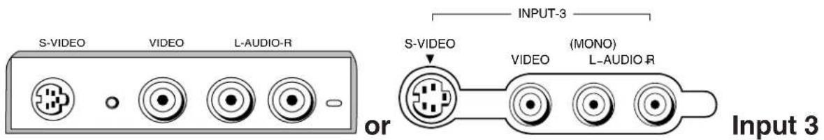
This input can be used for convenient connection of a camcorder or other video device to the TV. Please note that if you connect to the S-VIDEO terminal, the VIDEO terminal is deactivated. The VIDEO terminal is active when there is no S-Video connection.
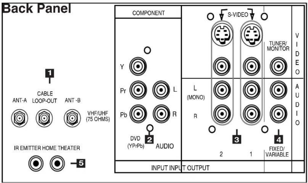

1 Antenna (ANT-A, CABLE LOOP-OUT, ANT-B)
ANT-A and ANT-B receive signals from VHF/UHF antennas or a cable system. LOOP OUT sends the ANT-A signal out to another component, such as a cable box or VCR.
2 Component Input
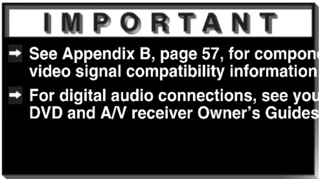
This input can be used for the connection of A/V equipment with component video outputs, such as a DVD player. Please see Appendix B, page 57, for signal compatibility.
3 Inputs 1-2
These inputs can be used for the connection of a VCR, Super VHS (S-VHS) VCR, laser disc player, or other A/V device to the TV. Please note that if you connect to the S-VIDEO terminal, the VIDEO terminal is deactivated. The VIDEO terminal is active when there is no S-Video connection.
4 Output (Tuner/Monitor)
The Tuner/Monitor Output sends the TV audio and video signals, excluding component video, to an A/V receiver or other equipment.
5 IR Emitter Home Theater (System 4 Home Theater IR Control)
Models VS-601719 and VS-70709
Connecting IR emitters here allows the TV to automatically change a digital A/V receiver's input in a home theater setup, and pass IR commands to other A/V devices.

How Connections Affect the PIP
To see a picture in the PIP inset, you may need to select an input source. If the only input connected is ANT-A, then both the main picture and the PIP insert will be from that input source. If other video equipment is connected, you may be able to view these input sources as the PIP insert. When connecting your new Mitsubishi bigscreen, it is important to understand which main picture and PIP input sources can and cannot be used together. Table 1 shows which inputs can and cannot be used together and their limitations. To see which input is being displayed as the main picture, press INFO on the TV remote control. To see which input is being displayed as the PIP and for PIP operating instructions, see Operation of PIP, pages 50-51.
| MAIN\PIP | A-TNA | B-TNA NPS | NPU | |
| A-TNA | OK | NO PIP | OK | NO COMPONENT PIP |
| B-TNA | OK | OK^* | OK | NO COMPONENT PIP |
| NPS | OK | OK | OK | NO COMPONENT PIP |
| NPU | OK | OK | OK | NO COMPONENT PIP |
Table 1. How connections affect the PIP. *PIP must be the same channel as MAIN.
How Connections Affect the System 4 Home Theater IR Control
Models VS-60719 and VS-70709
The Mitsubishi System 4 Home Theater IR Control is a special feature that makes it easier to use your TV with a digital surround sound A/V receiver. Once your equipment is properly connected and set up, your TV and digital A/V receiver will change inputs together, to match your selected video input with the corresponding audio input.
When you change inputs on your TV to watch different video products, your TV will send signals via your remote control and the infrared emitters to your digital A/V receiver
to change inputs. You will automatically hear the high quality digital surround sound from digital products like your DVD player, and high quality analog stereo or surround sound from non-digital products like your VCR.
Additionally, all IR remote signals from your Mitsubishi remote or other manufacturers remote will be passed through your TV to your A/V devices. Your A/V devices can be hidden or behind cabinet doors and controlled by pointing the remote at the TV.
Special Setups: A/V Equipment (For System 4 Home Theater IR Control)

VCR: Connect the cables to the TV as directed on page 17, with the following exception: Connect the audio output connection to the appropriate input on the back of the A/V receiver (as shown in table 1).
DVD: Connect the cables as directed on page 19 (using the COMPONENT input), with the following exception: Connect the digital audio output connection on the DVD player to the appropriate digital input on the back of the digital A/V receiver (as shown in table 1).
A/V Receiver: Connect as directed on page 18, then complete the following two steps. Use an S-Video cable in step 1 if you have an S-Video VCR. The TV outputs should be connected to the A/V receivers input marked TV.
- Auto Standby: ON (See your A/V receiver's Owner's Guide for this procedure). For all TV use, the sound will come from the A/V receiver. Not available with all A/V receivers.
- Digital Input Assignment for DVD: Assign the digital input you used for your DVD player to the A/V receiver's DVD input selector. This procedure is explained in your A/V receiver's Owner's Guide.
Infrared Emitter: Connect as shown on page 20.
Special Setups: TV
Menu selection for A/V connections, page 41.
•TV Speakers: OFF
•Audio Output: Fixed
Remote Control, pages 24-25.
- Set the slide switch to the TV position and follow the programming instructions using the A/V receiver code appropriate for your A/V receiver, page 25 (figure 5).
| Brand Model | The products listed at the top of this column should connect to the inputs on the back of the appropriate A/V receiver listed to the left. | ||||
| TV / Cable | SAT/DBS/DTV | VCR | DVD | ||
| Mitsubishi | M-VR800 / M-VR1000 | TV | VCR2 | VCR1 | DVD |
| Mitsubsihi | M-VR700 / M-VR900 | TV | CABLE/DBS | VCR | DVD |
| Denon | RX-888V | TV/DBS | VCR2 | VCR1 | DVD/LD |
| JVC | VR-2080 | TV | VIDEO 2 | VCR 1 | DVD |
| Kenwood | TX-DS575 | AV AUX | LD | VIDEO 1 | DVD |
| Onkyo | VSX-21 | VIDEO 3 | VIDEO 2 | VIDEO 1 | DVD |
| Pioneer | STR-DE825 | TV/SAT | VIDEO 2 | VCR 1 | DVD/LD |
| Sony | RX-V2095 | TV/DBS | VIDEO 2 | VIDEO 1 | DVD/LD |
| Yamaha | TV/DBS | VCR 2 | VCR1 | DVD/LD | |
Table 1. A/V receiver back panel input table

Connecting an Antenna, Wall Outlet Cable, or Cable Box
Separate UHF and VHF Antennas
(Figure 1)
1 Connect the UHF and VHF antenna leads to the UHF/VHF combiner.
2 Push the combiner onto ANT-A on the TV back panel.
→ UHF/VHF combiners are not provided with the TV. They should be available at most electronic stores.

Figure 1. Connecting separate UHF and VHF antennas.
Twin Lead Antenna, Coaxial Lead Antenna, or Wall Outlet Cable
For antenna with twin flat leads (Figure 2)
1 Connect the 300ohm twin leads to the transformer.
2 Push the 75ohm side of the transformer onto ANT-A on the TV back panel.
300ohm to 75ohm matching transformers are not provided with the TV. They should be available at most electronic stores.
For cable or antenna with coaxial lead (Figure 2)
3 Connect the incoming cable to ANT-A on the TV back panel.
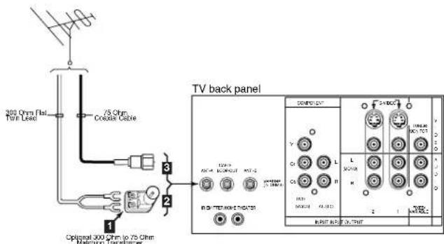
Figure 2. Connecting twin lead antenna, coaxial lead antenna, or wall outlet cable.
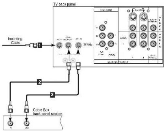
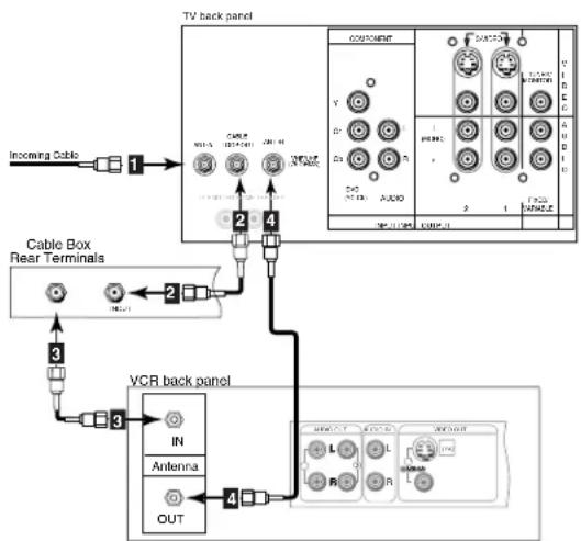
Cable Box
(Figure 3)
1 Connect the incoming cable to ANT-A on the TV back panel.
→ Connect two coaxial cables as follows:
2 One from LOOP-OUT on the TV back panel to IN on the cable box back panel.
3 One from OUT on the cable box back panel to ANT-B on the TV back panel.
flowchart
graph TD
    A["Incoming Cable"] --> B["TV back panel"]
    B --> C["Cable Box back panel section"]
    C --> D["1"]
    C --> E["2"]
    C --> F["3"]
    D --> G["1"]
    E --> H["2"]
    F --> I["3"]
    G --> J["4"]
    H --> K["5"]
    I --> L["6"]
    J --> M["7"]
    K --> N["8"]
    L --> O["9"]
    M --> P["10"]
    N --> Q["11"]
    O --> R["12"]
    P --> S["13"]
    Q --> T["14"]
    R --> U["15"]
    S --> V["16"]
    T --> W["17"]
    U --> X["18"]
    V --> Y["19"]
    W --> Z["20"]
Figure 3. Connecting the cable box.
Connecting a VCR
flowchart
graph TD
    A["Incoming Cable"] --> B["1"]
    B --> C["TV back panel"]
    C --> D["2"]
    C --> E["3"]
    D --> F["OUT"]
    E --> G["Antenna"]
    F --> H["VCR back panel"]
    G --> I["IN"]
    G --> J["OUT"]
    H --> K["Antenna"]
    H --> L["OUT"]
    K --> M["IN"]
    K --> N["OUT"]
    L --> O["Antenna"]
    L --> P["OUT"]
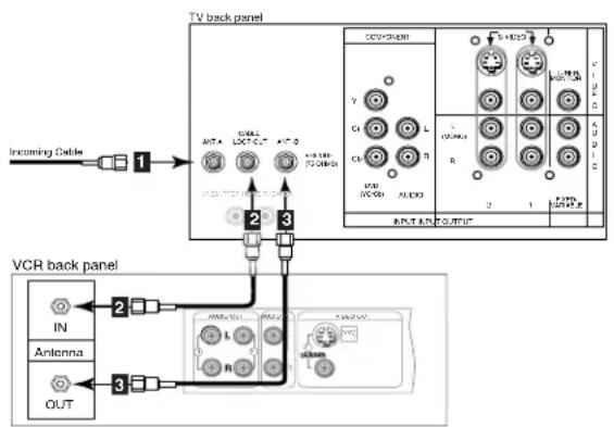
Figure 1. Connecting VCR with antennas or wall outlet cable.
flowchart
graph TD
    A["Incoming Cable"] --> B["1"]
    B --> C["Cable Box Rear Terminals"]
    C --> D["2"]
    D --> E["VCR back panel"]
    E --> F["3"]
    F --> G["IN"]
    F --> H["Antenna"]
    F --> I["OUT"]
    E --> J["4"]
    J --> K["TV back panel"]
    K --> L["CABLE"]
    K --> M["AVOC"]
    K --> N["OUTPUT"]
    K --> O["AC/DC"]
    K --> P["LED"]
Figure 2. Connecting VCR with cable box.
flowchart
graph TD
    A["TV back panel"] --> B["1: Access only, new cable type"]
    A --> C["2: High speed I/O/DC generator"]
    A --> D["3: Low speed I/O/DC generator"]
    A --> E["4: High speed I/O/DC generator"]
    A --> F["5: Low speed I/O/DC generator"]
    A --> G["6: High speed I/O/DC generator"]
    A --> H["7: Low speed I/O/DC generator"]
    A --> I["8: High speed I/O/DC generator"]
    A --> J["9: Low speed I/O/DC generator"]
    A --> K["10: High speed I/O/DC generator"]
    A --> L["11: Low speed I/O/DC generator"]
    A --> M["12: High speed I/O/DC generator"]
    A --> N["13: Low speed I/O/DC generator"]
    A --> O["14: High speed I/O/DC generator"]
    A --> P["15: Low speed I/O/DC generator"]
    A --> Q["16: High speed I/O/DC generator"]
    A --> R["17: Low speed I/O/DC generator"]
    A --> S["18: High speed I/O/DC generator"]
    A --> T["19: Low speed I/O/DC generator"]
    A --> U["20: High speed I/O/DC generator"]
    A --> V["21: Low speed I/O/DC generator"]
    A --> W["22: High speed I/O/DC generator"]
    A --> X["23: Low speed I/O/DC generator"]
    A --> Y["24: High speed I/O/DC generator"]
    A --> Z["25: Low speed I/O/DC generator"]
    A --> AA["26: High speed I/O/DC generator"]
    A --> AB["27: Low speed I/O/DC generator"]
    A --> AC["28: High speed I/O/DC generator"]
    A --> AD["29: Low speed I/O/DC generator"]
    A --> AE["30: High speed I/O/DC generator"]
    A --> AF["31: Low speed I/O/DC generator"]
    A --> AG["32: High speed I/O/DC generator"]
    A --> AH["33: Low speed I/O/DC generator"]
    A --> AI["34: High speed I/O/DC generator"]
    A --> AJ["35: Low speed I/O/DC generator"]
    A --> AK["36: High speed I/O/DC generator"]
    A --> AL["37: Low speed I/O/DC generator"]
    A --> AM["38: High speed I/O/DC generator"]
    A --> AN["39: Low speed I/O/DC generator"]
    A --> AO["40: High speed I/O/DC generator"]
    A --> AP["41: Low speed I/O/DC generator"]
    A --> AQ["42: High speed I/O/DC generator"]
    A --> AR["43: Low speed I/O/DC generator"]
    A --> AS["44: High speed I/O/DC generator"]
    A --> AT["45: Low speed I/O/DC generator"]
    A --> AU["46: High speed I/O/DC generator"]
    A --> AV["47: Low speed I/O/DC generator"]
    A --> AW["48: High speed I/O/DC generator"]
    A --> AX["49: Low speed I/O/DC generator"]
    A --> AY["50: High speed I/O/DC generator"]
    A --> AZ["51: Low speed I/O/DC generator"]
    A --> BA["52: High speed I/O/DC generator"]
    A --> BB["53: Low speed I/O/DC generator"]
    A --> BC["54: High speed I/O/DC generator"]
    A --> BD["55: Low speed I/O/DC generator"]
    A --> BE["56: High speed I/O/DC generator"]
    A --> BF["57: Low speed I/O/DC generator"]
    A --> BG["58: High speed I/O/DC generator"]
    A --> BH["59: Low speed I/O/DC generator"]
    A --> BI["60: High speed I/O/DC generator"]
    A --> BJ["61: Low speed I/O/DC generator"]
    A --> BK["62: High speed I/O/DC generator"]
    A --> BL["63: Low speed I/O/DC generator"]
    A --> BM["64: High speed I/O/DC generator"]
    A --> BN["65: Low speed I/O/DC generator"]
    A --> BO["66: High speed I/O/DC generator"]
    A --> BP["67: Low speed I/O/DC generator"]
    A --> BQ["68: High speed I/O/DC generator"]
    A --> BR["69: Low speed I/O/DC generator"]
    A --> BS["70: High speed I/O/DC generator"]
    A --> BT["71: Low speed I/O/DC generator"]
    A --> BU["72: High speed I/O/DC generator"]
    A --> BV["73: Low speed I/O/DC generator"]
    A --> BW["74: High speed I/O/DC generator"]
    A --> BX["75: Low speed I/O/DC generator"]
    A --> BY["76: High speed I/O/DC generator"]
    A --> BZ["77: Low speed I/O/DC generator"]
Figure 3. Connecting the VCR Audio/Video.
Antennas or Wall Outlet Cable
(Figure 1)
1 Connect the incoming cable to ANT-A on the TV back panel.
→ Connect two coaxial cables as follows:
2 One from LOOP-OUT on the TV back panel to ANTENNA IN on the VCR back panel.
3 One from VCR back panel ANTENNA OUT to ANT-B on the TV back panel.
4 Now complete figure 3, steps 1-2.
Cable Box
(Figure 2)
1 Connect the incoming cable to ANT-A on the TV back panel.
Connect three coaxial cables as follows:
2 One from LOOP-OUT on the TV back panel to IN on the back of the cable box.
3 One from OUT on the back of the cable box to ANTENNA IN on the VCR back panel.
4 One from ANTENNA OUT on the VCR back panel to ANT-B on the TV back panel.
5 Now complete figure 3, steps 1-2.
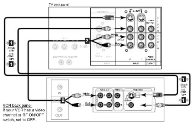
Composite Video with Audio or S-Video with Audio
(Figure 3)
1 Connect a video cable from VIDEO OUT on the VCR back panel to VIDEO INPUT-1, or INPUT-2 on the TV back panel, or INPUT-3 on the TV Front Control Panel.
If you have an S-VHS VCR, follow the same steps using the S-Video terminals on the VCR and TV (in place of the composite terminals).
2 Connect a set of audio cables from AUDIO OUT on the VCR back panel to AUDIO INPUT-1, or INPUT-2 on the TV back panel, or INPUT-3 on the TV Front Control Panel. The red cable connects to the R (right) channel and the white cable connects to the L (left) channel. If your VCR is mono (non-stereo), connect only the white (left) cable.


Connecting an Audio Receiver
Stereo Audio System
(Figure 1)
1 Connect the audio cables from AUDIO MONITOR OUTPUT on the TV back panel to TV IN or AUX IN terminals on the back of the audio system. The red cable connects to the R (right) channel, and the white cable connects to the L (left) channel.
2 Turn off the TV's speakers through the Audio/Video Settings Menu, page 41.
3 Set the audio system's input to the TV or AUX position to hear the TV's audio through your stereo system.
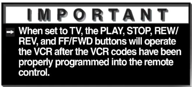
IMPORTANT
Additional connection cables are not provided with the TV. They should be available at most electronic stores.
A/V Receiver
(Figure 2)
1 Connect a video cable or S-Video cable from VIDEO MONITOR OUT on the back of the A/V receiver to VIDEO INPUT-1 on the TV back panel.
2 Connect a video cable from VIDEO MONITOR OUTPUT on the TV back panel to VIDEO TV IN on the back of the A/V receiver.
3 Connect a set of audio cables from AUDIO MONITOR OUTPUT on the TV back panel to AUDIO TV IN on the back of the A/V receiver. The red cable connects to the R (right) channel, and the white cable connects to the L (left) channel.
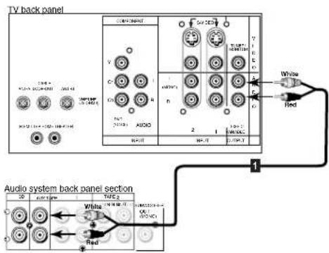
Figure 1. Connecting the Stereo Audio System
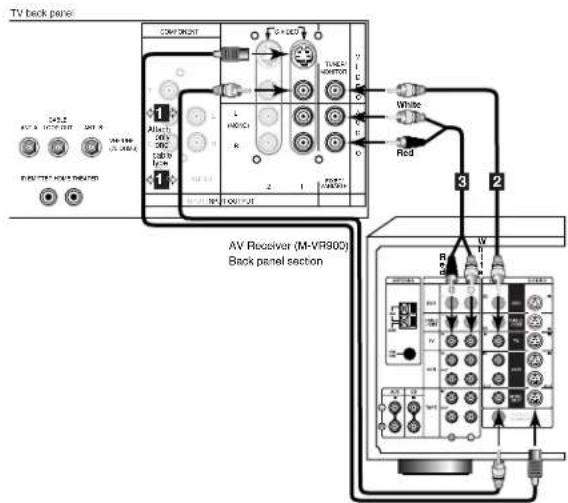
Figure 2. Connecting the A/V Receiver.
IMPORTANT
→ Please see your A/V receiver Owner's Guide for more detailed connections.
WARNING: Do not display the same stationary images on the screen for more that 15% of your total TV viewing in one week. Examples of stationary images are letterbox top/bottom bars from DVD or other video sources, side bars when showing standard TV pictures on widescreen TV's, stock market reports, video game patterns, station logos, web sites, or stationary computer images. Such patterns can unevenly age the picture tubes causing permanent damage to the TV. Please see pages 21 and 52 for a detailed explanation.

Connecting a DVD Player
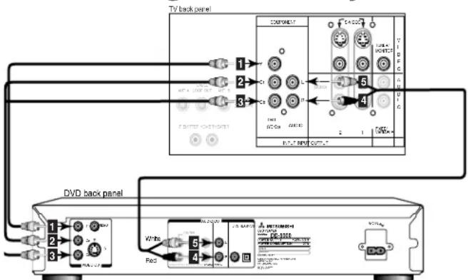
Figure 1. Connecting the DVD player.
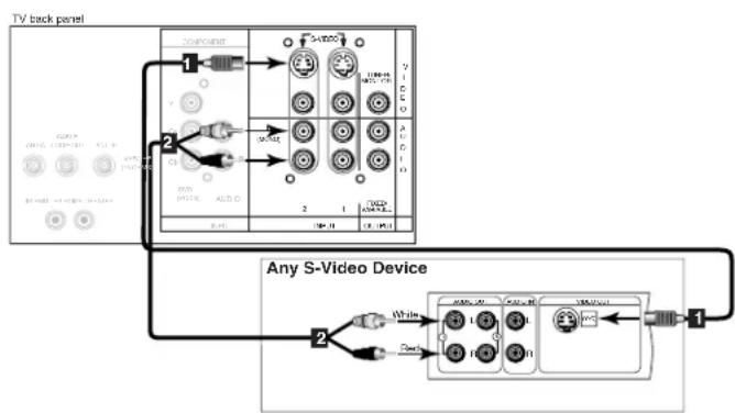
Connecting an S-Video Device
flowchart
graph TD
    A["TV back panel"] --> B["Component"]
    B --> C["1"]
    B --> D["2"]
    C --> E["3"]
    D --> F["4"]
    E --> G["5"]
    F --> H["6"]
    G --> I["7"]
    H --> J["8"]
    I --> K["9"]
    J --> L["10"]
    K --> M["11"]
    L --> N["12"]
    M --> O["13"]
    N --> P["14"]
    O --> Q["15"]
    P --> R["16"]
    Q --> S["17"]
    R --> T["18"]
    S --> U["19"]
    T --> V["20"]
    U --> W["21"]
    V --> X["22"]
    W --> Y["23"]
    X --> Z["24"]
    Y --> AA["25"]
    Z --> AB["26"]
Figure 2. Connecting an S-Video Device.
DVD Player with Component Video
(Figure 1)
Connect the Component Video cables from Y/Cr/Cb or Y/Pr/Pb VIDEO OUT on the back of the DVD player to COMPONENT on the TV back panel, matching the correct components:
1 Y to Y
2 Cr or Pr to Pr
3 Cb or Pb to Pb
Connect a set of audio cables from AUDIO OUT on the back of the DVD player to COMPONENT AUDIO Input on the TV back panel. The red cable 4 connects to the R (right) channel, and the white cable 5 connects to the L (left) channel.
S-Video Device
(Figure 2)
1 Connect an S-Video cable from S-VIDEO OUT on the device back panel to S-VIDEO INPUT-1, or INPUT-2 on the TV back panel, or INPUT-3 on the TV Front Control Panel.
2 Connect a set of audio cables from AUDIO OUT on the device back panel to AUDIO INPUT-1 or INPUT-2 on the TV back panel. The red cable connects to the R (right) channel and the white cable connects to the L (left) channel. If your device is mono (non-stereo), connect only the white (left) cable.

Connecting the System 4 Home Theater IR Control
Models VS-60719, VS-70709. (Figure 1)
1 Connect the IR emitter to IR EMITTER HOME THEATER on the TV back panel.
2 Place the IR emitter cable under or along the side of the A/V device. Place the IR lens directly in front of the A/V device's infrared signal receiver. Infrared signal receivers are usually behind the front translucent panel of the device.
3 Place unused transmitters in an out-of-the-way location.
4 For permanent installation of the IR emitter cable, use the included adhesive tape to secure the bottom of the emitter to the anchoring object of your choice.
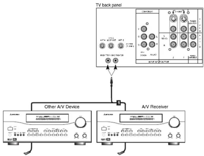
flowchart
graph TD
    A["TV back panel"] --> B["Other A/V Device"]
    A --> C["A/V Receiver"]
    B --> D["Component 1"]
    C --> E["Component 2"]
    D --> F["THICKY MONTOO"]
    E --> G["THICKY MONTOO"]
    F --> H["L/ON/O"]
    G --> I["R"]
    H --> J["2"]
    I --> K["1"]
    J --> L["OUTPUT"]
    K --> M["OUTPUT"]
Figure 1. Connecting the System 4 Home Theater IR Control.

Warning: Do not leave stationary or letterbox images on-screen for extended periods of time. Mix the types of pictures shown. Uneven picture tube aging is NOT covered by your warranty.
The normal use of a TV should include a mixture of TV picture types. The most frequently used picture types should fill the screen with constantly moving images rather than stationary images or patterns. Displaying the same stationary patterns over extended periods of time, or displaying the same stationary pattern frequently can leave a subtle but permanent ghost image. To avoid this, mix your viewing pattern. Do not show the same stationary image for more than 15% of your total TV viewing in any one week. Display constantly moving and changing images that fill the screen whenever possible.
This projection TV uses picture tubes to project the image onto the screen. All picture tubes age with use. As they age, their light output is gradually reduced. Normal TV pictures fill the screen with constantly changing images. Under these conditions, picture tubes age at an even rate across the entire screen. This maintains a TV picture that is evenly bright over the whole screen. Stationary images or images that only partially fill the screen (leaving black or colored bars to fill the screen), when used over extended periods of time or when viewed repeatedly, can cause uneven aging of the phosphors and leave subtle ghosts of the stationary images in the picture Still or stationary images may be received from broadcasters, cable channels, satellite channels, DVD discs, video tapes, laser discs, on-line services, web/internet searching devices, video games, and digital TV tuner/converter boxes. Examples of these types of images can be, but are not limited to the following:
Letterbox top/bottom black bars: shown at the top and bottom of the TV screen when you watch a widescreen (16:9) movie on a standard (4:3) TV.
Side bar images: solid bars shown on each side of an image when watching a standard (4:3) program on a wide-screen (16:9) TV.
Stock-market report bars: ticker running at the bottom of the TV screen.
Shopping channel logos & pricing displays: bright graphics that are shown constantly or repeatedly in the same location.
→ Video game patterns and scoreboards
Bright station logos: moving or low-contrast graphics are less likely to cause uneven aging of the picture tubes.
On-line (internet) web sites: or any other stationary or repetitive computer style images.
If you have questions regarding your television, call
Consumer Relations
at (800) 332-2119, or email us at
MDEA ser vice@bigscreen.mea.com.com
To order replacement or additional remote controls or owner's
guides
call (800) 553-7278
or
visit our website at www.mitsublish-tv.com

natural_image
Abstract geometric shapes with white highlights against a black background (no text or symbols)Part III

natural_image
Illustration of an open cardboard box with two metallic blades emerging from the top (no text or symbols)
natural_image
Abstract geometric shapes with gradient shading against black background (no text or symbols)Setup
Programming the Remote Control:
To Control Other A/V Products .... 24-25
To Activate the System 4 IR Home
Therater IR ControlYS-60719 & VS-70709 26-27
ViewPoint® on-screen menu system.....28
Menu Screens (Overview)... 29-30
Setup 31
Memorize Channels ....31
Clock 31
Language....31
Closed Captions......32
V-Chip Parent Lock ...... 33-35
Channel Edit ......36
Advanced Features ....37
Timer 37
Convergence ....38
Advanced Convergence .....39
Special Features ....39
Audio/Video Settings...... 40-41
A/V Setting Descriptions ..... 42-43

Programming the Remote Control: To Control Other A/V Products
To Program the Remote to Control Other Brands of Audio and Video Products:
(Figures 1-5)
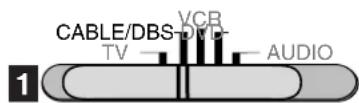
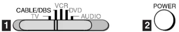
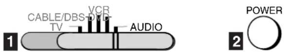
1 Move the slide switch at the top of the remote to the product you want to control.
2 Press and hold the POWER button on the remote control.
3 Enter the first three digit code listed for your equipment, and then release the POWER button on the remote control.
4 Point the remote control at the equipment and press the POWER button. If the equipment responds, the remote control is properly programmed to operate the equipment. If the equipment does not respond, repeat steps 2-4 with the next three digit code listed in step 3 for your equipment.

| 3 Cable Box Codes | ||
| Cable box brand | Code to enter: | If your cable box code is not listed here, please see page 62 for a complete listing. |
| General Instruments | 111, 119, 120, 121, 122, | |
| Jerrold | 123, 124, 125, 126, 127 | |
| Oak | 102, 137, 139 | |
| Pioneer | 101, 116 | |
| Scientific Atlanta | 111, 112, 113 | |
| Zenith | 100, 117 | |
| To reset to default code, enter 000 | ||
Figure 1. Programming the remote to control your cable box.
3 Satellite Receiver Codes
| Satellite brand | Code to enter: | If yoursatelliterceivercode is notlisted here,please seepage 62for acompletelisting. |
| Mitsubishi - DBS | 173 | |
| Dishnetwork | 175 | |
| Hughes - DSS | 173 | |
| RCA - DSS | 176 | |
| Sony - DSS | 177 | |
| Toshiba - DSS | 170 | |
| Panasonic - DSS | 174 | |
| Primestar | 178 | |
| To reset to default code, enter 000 | ||
Figure 2. Programming the remote to control your satellite receiver.

3 VCR Codes
| VCR brand | Code to enter: | If your VCR code is not listed here, please see page 62 for a complete listing. |
| Mitsubishi | 001, 002 | |
| Hitachi | 020, 043, 065 | |
| JVC | 030, 054, 059 | |
| Phillips / Magnivox | 043, 044, 051 | |
| Panasonic | 041, 042, 043 | |
| RCA | 020, 053, 065 | |
| Sony | 048, 049, 050 | |
| Toshiba | 021, 066 | |
| To reset to default code, enter 000 | ||
Figure 3. Programming the remote to control your VCR.
Programming the Remote Control: To Control Other A/V Products

3 DVD/LDP Player Codes
| DVD/LDP brand | Code to enter: | If your DVD code is not listed here, please see page 62 for a complete listing. |
| Mitsubishi (DVD) | 003 | |
| Mitsubishi (LDP) | 016, 017 | |
| Panasonic | 250 | |
| Pioneer DVD (LDP) | 252 (016, 017) | |
| Sony | 254 | |
| Toshiba | 253 | |
| To reset to default code, enter 000 | ||
Figure 4. Programming the remote to control your DVD/LDP.
3 A/V Receiver Codes
| Audio brand | Code to enter: | If youraudiocode is notlisted here,please seepage 62for acompletelisting. |
| Mitsubishi A/V receiverand/or CD player | Set M-VR1000 or M-VR800 to 015Set M-VR900 or M-VR700 to 010 | |
| Denon | 234, 235, 236 | |
| Kenwood | 200, 208 | |
| JVC | 232, 233 | |
| Onkyo | 209, 214 | |
| Pioneer | 205, 207 | |
| Sony | 222 | |
| Yamaha | 201, 208 | |
| To reset to default code, enter 000 | ||
Figure 5. Programming the remote to control your A/V receiver.
IMPORTANT
→ If the slide switch is set to TV when you enter an A/V receiver code, VOLUME and MUTE will control the A/V receiver rather than the TV. To return volume and mute control to the TV, set the slide switch to TV, press and hold POWER and enter 000.
After entering the correct codes for each position of the remote control, use the slide switch to select the product to control when an operational button is pressed. If you enter a code from the AUDIO chart while the slide switch is set to TV, the volume and mute functions change to match the A/V receiver. This is useful when using an A/V receiver with the TV all the time. In all other cases, only one of the below devices is allowed for each slide switch position.
TV position:
TV
→ A/V receiver (volume and mute only)
Cable/DBS position:
Cable box
→ Satellite receiver
VCR position:
VCR
DVD position:
DVD
→ LD Player
Audio position:
→ A/V receiver
Mitsubishi CD player [If you have a Mitsubishi A/V receiver, the audio position may be used in conjunction with select Mitsubishi CD players. Your audio position must be programmed to either 010 or 011. Plug the CD player power cord into a switched outlet on the back of your A/V receiver. Pressing the POWER button will then turn on your A/V receiver, in turn, turning on your CD player. On select CD players, the transport controls (FF, Play, Rew, etc.) in the audio position will operate the CD player.]
IMPORTANT
→ Some manufacturers may change their products, or they may use more than one remote control system. If this is the case, your remote control may not be able to operate your VCR, DVD, cable box, satellite receiver, or A/V receiver.

Programming the Remote Control: To Activate the System 4 Home Theater IR Control
Models VS-60719 and VS-70709
Activation of the System 4 Home Theater IR Control
You can, with certian digital A/V receivers, set up the remote control to automatically select the correct audio input when you press the HOME THEATER button. At the same time, the TV will select the correct video input. This allows you to watch your best type of video (Component, S-Video) with your best type of audio (Dolby Digital, Pro Logic, etc.) conveniently. See System 4 Home Theater IR Control, page 20, for connection instructions.
Once properly activated, when the HOME THEATER button is pressed, System 4 Oper-ates in 2 parts:
AUDIO Changes a compatible digital A/V receiver to the correct input for the device you wish to operate.
VIDEO Changes the TV to the correct input for the device you wish to operate.
Both functions can operate simultaneously with one touch of the HOME THEATER button. However, you may activate only one if you desire (video to control the TV or audio to control the A/V Receiver). The remote control must be programmed to the appropriate A/V Receiver code prior to the activation of the audio portion (see To Program the Remote to Control Other Brands of Audio and Video Products, page 24).
To Activate the Audio Portion:
1 Press and hold the HOME THEATER button.
2 Press and release the AUDIO button.
To Activate the Video Portion:
(Figure 1)
1 Press and hold the HOME THEATER button.
2 Press and release the VIDEO button.
3 Name the TV input as instructed.

| 3 Name TV Input as Shown Below (see pg 36 for naming help) | |
| Device You Are Using | Name Input |
| Cable Box connected to ANT-A or ANT-B | Cannot be named |
| Cable Box connected to Inputs 1-3 | CABLE |
| Satellite Receiver connected to any input | DBS |
| VCR connected to Inputs 1-3 | VCR |
| DVD connected to Inputs 1-3 | DVD |
Figure 1. Activating the video portion of System 4.
Programming the Remote Control: To Activate the System 4 Home Theater IR Control
Models VS-60719 and VS-70709
Testing System 4 for Proper Setup
1 Move the slide switch to the position you wish to test.
2 Point the remote at the TV.
3 Press and release the HOME THEATER button. If the audio portion has been properly setup, your A/V receiver will have changed to the appropriate input as indicated in table 1, page 15. If the video connection of your System 4 has been properly setup, your TV will have changed to the appropriate input.
AUDIO If the A/V Receiver did not change inputs...
1 Repeat Special Setups, page 15, and retest.
2 Reposition IR emitter(s) and retest
3 Repeat To Activate the Audio Portion, page 26, and retest.
If your A/V receiver is still not responding to the commands from your remote control, you may have an incompatible A/V receiver. Proceed to Deactivating the System 4 Home Theater IR Control, on this page.
IMPORTANT
→ System 4 is designed for use with A/V recers that have at least 4 inputs. A/V receive with fewer may be only partially compatible
AUDIO If the A/V Receiver changed to an input other than the one indicated in table 1, page 15...
1 Connect the audio output from your A/V device to the A/V receiver input that your A/V receiver DID change to, and retest.
VIDEO If the TV did not change inputs...
1 Repeat To Activate the Video Portion, page 26, and retest.
Deactivating the System 4 Home Theater IR Control
1 Simultaneously press the CANCEL button and the HOME THEATER button.


The ▶ViewPoint® System
Your TV has Mitsubishi's exclusive ViewPoint® on-screen operating system, which provides on-screen information for menu choices and changes (Figure 1).
A picture (icon) will be highlighted when selected with the ADJUST arrows. The icon indicates that a submenu can be displayed or an automatic function can be started by selecting the icon and pressing ENTER.
A square button indicates that your menu selections will be made on the current menu by selecting the square button and pressing ENTER.
The ▶ViewPoint® includes the following special features:
The currently selected icon or button is highlighted with a yellow outline and the text color will be yellow.
On-screen instructions provide complete menu choice information.
Some on-screen menu options must be set before other options are available. For example, "Set the Timer" will only be possible if "Clock Time" and "Set Day" have been set.
The following buttons on your remote control will help you to navigate within the ViewPoint® system (Figure 2):
1 ADJUST ◀ or ▶ to select the menu item you want to change.
2 ADJUST ▲ or ▼ change the settings.
3 ENTER to enter into a menu, start an automatic function, or select a checkbox.
4 CANCEL to clear a setting, or stop an automatic function.
5 MENU to move back one menu screen at a time.
6 HOME to exit all menus and return to TV viewing.
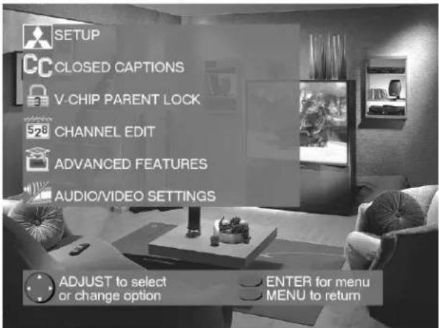
Figure 1. Main Menu: The Main Menu screen will always be the first screen that appears when you press the MENU button.
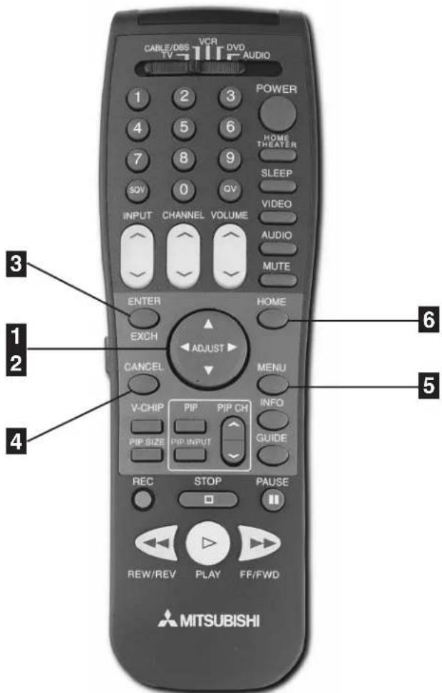
Figure 2. These buttons are used for navigation within the ▶ViewPoint® screen operating system.
Menu Screens (Overview)
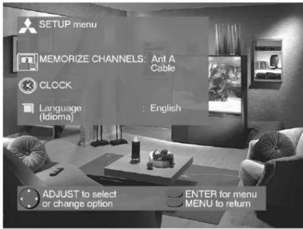
Figure 1. Setup menu.
SETUP Menu
(Figure 1)
You can put channels in memory, enter the CLOCK submenu, and select the menu system to display in English or Spanish (Español).


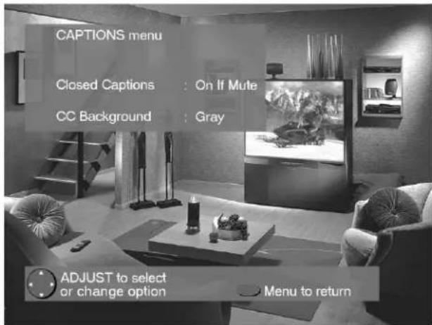
Figure 2. Captions menu.
CAPTIONS Menu
(Figure 2)
Display captions or text, and choose black or gray as the background color for the closed caption area.
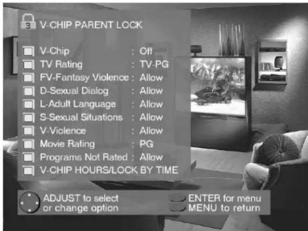
Figure 3. V-Chip Parent Lock menu.
V-CHIP PARENT LOCK Menu
(Figure 3)
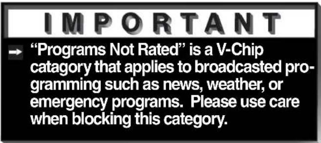
Block or allow programming based upon rating signals sent by the broadcast station, or by time.


Menu Screens (Overview)
CHANNEL EDIT Menu
(Figure 1)
Use to customize the channel information for Ant-A and Ant-B. Manually add or delete channels from memory, name channels for Ant-A and Ant-B, or add your favorite channels to the SQV (Super Quick View™)list.
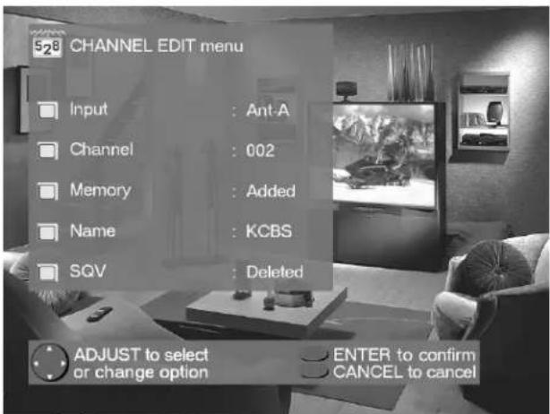
Figure 1. Channel Edit menu.
ADVANCED FEATURES Menu
(Figure 2)
Set your TV to turn on automatically, converge (align) the three main colors, display a blue screen when viewing an input with no signal, turn off the Front Panel Controls, and view the PIP Demo Mode.

Figure 2. Advanced Features menu.
AUDIO/VIDEO SETTINGS
(Figure 3)
Adjust some or all of the A/V settings. Each input can be set to your preferences. A/V Memory Reset on the menu allows you to return the A/V settings for the current input to the factory presets. A/V Reset on the front panel resets all inputs at once.
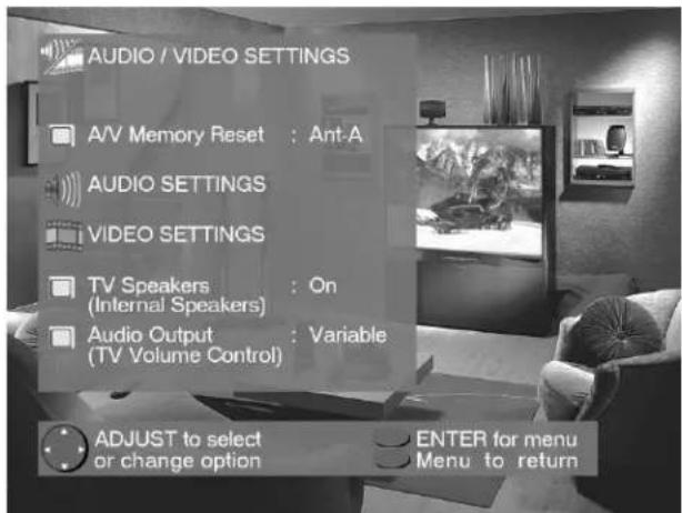
Figure 3. Audio/Video menu.
Setup Menu: Memorize Channels, Clock, and Language

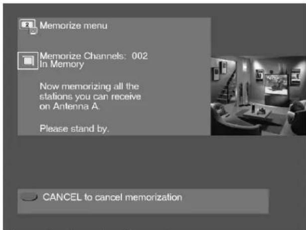
Figure 1. Memorize Channels menu.
Memorize Channels
(Figure 1)
This selection memorizes the channels your TV can receive and skips the unused or weak channels. You can stop memorization at any time by pressing CANCEL. Channels memorized prior to pressing CANCEL will stay in memory. After channels are memorized, you may select memorized channels in ascending or descending order by pressing the CHANNEL button on the remote control.
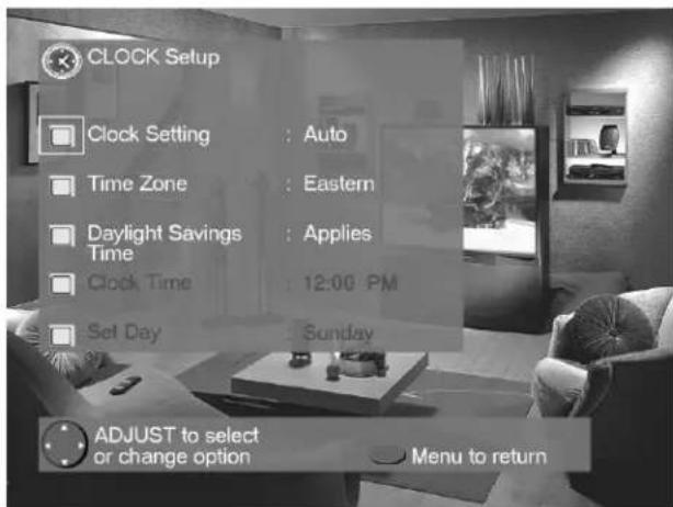
Figure 2. Clock Setup menu.
Clock Setup
(Figure 2)
Manually set the time for the TV, or select Auto and the TV will automatically set the time based upon Extended Data Service (XDS) time data. This time data is usually broadcast by your local PBS station.
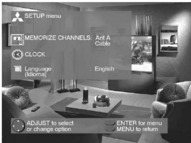
Figure 3. Language menu.
Language
(Figure 3)
Display the on-screen menus in either English or Spanish (Español). The first time your TV was powered on, you were requested to select an on-screen menu language. You may change your selection by pressing the ENTER button on the remote control.

Captions Menu: Closed Captions
Captions Menu
(Figure 1)
Broadcasters can send either Standard or Text closed captioning. Standard closed captioning follows the dialogue of the characters on-screen and displays in a small section of the screen. Text closed captioning often contains information such as weather or news and covers a large portion of the on-screen program. Your TV can decode four different standard and four different text closed captioning signals from each TV station. However, each TV station may broadcast only one or two closed captioning signals, or none at all.
Within the Captions menu, you can turn on or off the closed caption decoder, select the type of captions or text, and choose black or translucent gray as the background color for the closed caption area.
Closed Captions
(Figure 1)
The TV can display one of the following:
→ CC1, CC2, CC3, or CC4: Standard closed captioning signals.
Text1, Text2, Text3, or Text4: Text closed captioning signals.
On if mute: Closed captions when mute. When selected, the standard closed captioning signal (CC1) will turn on/off by pressing the MUTE button on the TV remote control.
→ Off: No closed captions.
CC Background
(Figure 1)
To make the closed captions easier to read, you can choose to display the background color as either black or translucent gray.
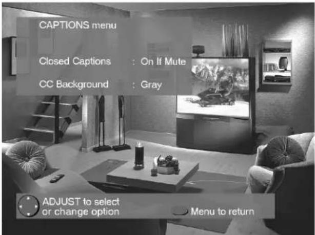
Figure 1. Captions menu.
IMPORTANT
→ When Text closed captioning is select a large black or gray box will appear of your TV screen if no signal is broadcast
IMPORTANT
The content of captions is determined the broadcaster. If your captions show strange characters, misspellings, or grammar, it is not a malfunction of the TV.
V-Chip Parent Lock Menu: V-Chip Lock
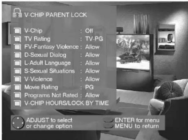
Figure 1. V-Chip Lock menu.
V-Chip Lock
(Figure 1)
The V-Chip Lock allows you to Block or Allow programs based upon rating signals sent by the broadcasting station. The TV comes from the factory with the V-Chip lock in the Off setting. You can turn the lock On within the V-Chip Menu. The factory preset is TV-PG, allowing only programs rated TV-PG or lower. You can change the blocking level to various TV or movie ratings, lettered categories, and by time. After changing channels or inputs, there may be up to a 5 second delay before the V-Chip lock takes effect. The V-CHIP button on the remote control enables you to conveniently turn the lock on or off.

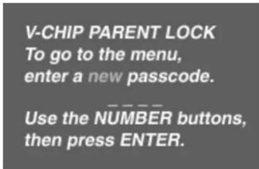
Figure 2. V-Chip Lock passcode screen (first-time entry)
Entry to the V-Chip Lock
(Figures 2)
The first time you select V-Chip Lock from the MAIN menu, press the V-CHIP button on the remote control, or after you have canceled your passcode you will see the screen shown in figure 2. Use the number buttons on the remote control to input a four-digit passcode, then press ENTER. You can delete a character and move back one space by pressing CANCEL. You can exit without inputting a passcode by pressing MENU or HOME. The next time you select V-Chip Lock from the MAIN menu, or press the V-CHIP button on the remote control, you will see a menu screen similar to the one in figure 3.
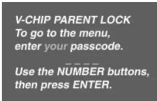
Figure 3. V-Chip Lock passcode screen (re-entry)

V-Chip Parent Lock Menu: V-Chip Lock
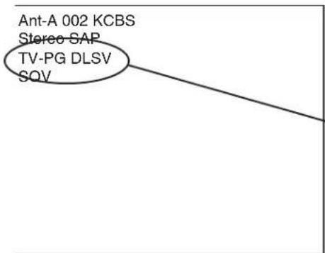
Figure 1. V-Chip signal information.
V-Chip Signal Information
(Figure 1)
When provided by the broadcaster, V-Chip signal information can be displayed by pressing the INFO button on the remote control. Rating guidelines are provided by broadcast stations. TV programs and made-for-TV movies can be blocked by the TV Rating and/or Categories signal. Made-for-theater and direct-to-video movies can be blocked by the Movie Rating signal.
| TV Ratingsand Descriptions | TV-YYouth | TV-Y7Youth 7+ Years | TV-GGeneral Audience | TV-PGParental Guidance | TV-1414+ Years | TV-MAMature Audience |
Table 1. V-Chip rating information that may be included with TV programs and made-for-TV movies. If you set the lock to TV-G; TV-Y, TV-Y7, and TV-G will be available, and TV-PG, TV-14, and TV-MA will be blocked.
| seirogeta and Descriptions | taCVTProgram Not Rated | VF DL S | Adult Language | Sexual Situations | VViolence | |
| Fantasy Violence | Sexual Dialog | |||||
Table 2. V-Chip category information that may be included with TV programs and made-for-TV movies. If you set the category L to be blocked; all programing carrying the L signal will be blocked (regardless of it's TV rating).
| sgretion and Descriptions | OFFV-Chip is off | GGeneral Audience | PGParental Guidance | PG-1313+ Years | RRestricted | CN18+ Years | XAdult |
Table 3. V-Chip rating information that may be included with made-for-theater and direct-to-video movies. If you set the lock for PG-13; G, PG, and PG-13 will be available, and R, NC-17, and X will be blocked.
V-Chip Parent Lock Menu: V-Chip Hours/Lock By Time
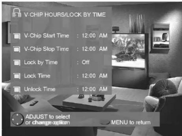
Figure 1. V-Chip Hours/Lock By Time menu.
V-Chip Hours/Lock By Time
(Figure 1)
V-CHIP HOURS/LOCK BY TIME will allow you to activate the V-Chip or lock the entire TV during specific hours.
V-Chip Start Time and V-Chip Stop Time
(Figure 1)
Select the times you would like the V-Chip to be Active. By setting the V-Chip Start Time and V-Chip Stop Time to the same time, the V-Chip will be active 24 hours a day.
Press ▲or ▼o slowly adjust the time. Press and hold ▲or ▼o quickly adjust the time.
Lock by Time, Lock Time, and Unlock Time
(Figure 1)
Lock by Time locks the entire TV based upon the Lock Time and Unlock Time. You must input your 4-digit passcode to use the TV when it is locked. By setting the Lock Time and Unlock Time to the same time, the Lock by Time will be active 24 hours a day.
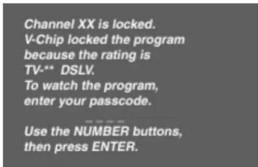
Figure 2. V-Chip Lock unlock passcode screen.
Unlock Passcode Screen
(Figure 2)
To view a V-Chip blocked program or to watch the TV during a scheduled lock time, you must enter your 4-digit passcode. The V-Chip block and Lock by Time will remain disabled until the TV is powered off and then on again.

Channel Edit Menu: Input, Channel, Memory, Name and SQV™
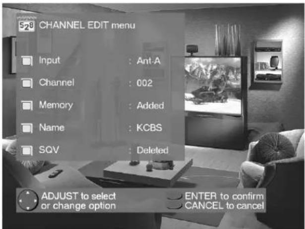
Figure 1. Channel Edit menu.
Input
(Figure 1)
Select Ant-A, Ant-B, or Inputs 1-3. For Ant-A and Ant-B, you can add or delete channels in memory, name channels, and add channels to the SQV (Super Quick View™) list. For Inputs 1-3, you can rename the input.
Channel
(Figure 1)
Select the channel you want to add or delete from memory, name, or add to the SQV Super Quick View™ list.
Memory
(Figure 1)
After all available channels have been memorized with Memorize Channels, page 31, weaker channels viewed with Ant-A or Ant-B can be added and unwanted channels can be deleted.
Use the CHANNEL button on the remote control to view memorized channels.
Name
(Figure 1)
Channels shown on Ant-A or Ant-B can be given names (up to four characters). After you enter a name, it will appear on the TV screen, next to the channel number. Inputs 1-3 can be renamed by scrolling through the following list: Audio, AUX, Cable, CAM(camcorder), DBS, DVD, Game, Laser, Surv (surveillance, or security), S-VHS, VCR, VCR2, VHS, or Off.
SQV (Super Quick View™) Using The Menu Screen
(Figure 1)
SQV (Super Quick View™) allows you to put together a list of your favorite channels from Ant-A and Ant-B. You can quickly look through the list using the SQV button. Once you have added a channel to the SQV memory, "SQV" will appear under the channel number any time the channel number is displayed on the TV screen.
SQV (Super Quick View™) Using The Remote Control
Adding SQV channels using the remote control:
1 Use the CHANNEL or number buttons to select the channel you want to add to add to the list.
2 Press and hold the SQV button for about 3 seconds. The letters "SQV" will appear under the channel number, indicating that the channel has been added to the Super Quick View™ memory.
Removing SQV channels using the remote control:
1 Press the SQV button repeatedly to select the channel to be removed from the list.
2 While the channel number and SQV indicator are still displayed on the screen, press the CANCEL button. If the CANCEL button is not pressed before the SQV indicator disappears, the channel will not be removed.
3 When the SQV indicator disappears, the channel has successfully been removed.
Advanced Features Menu: Timer
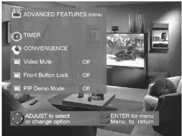
Figure 1. Advanced Features menu.
Timer
(Figure 1)
The timer will automatically turn the TV on (if it is off) at the time you schedule and select.


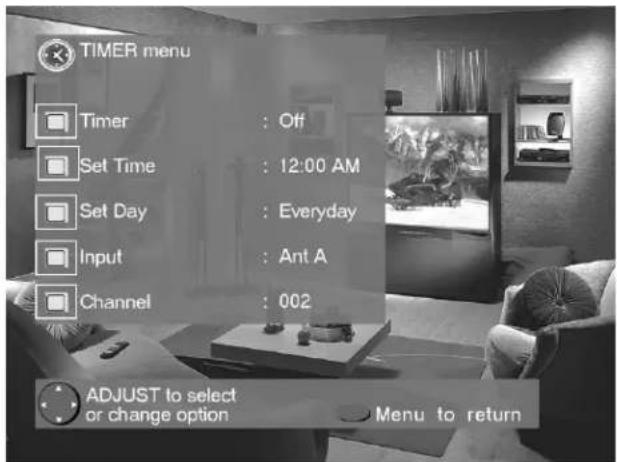
Figure 2. Timer menu.
Set Time
Select the hour and minute, including AM or PM, when the TV is to turn on.
Press ▲or ▼o slowly adjust the time. Press and hold ▲or ▼o quickly adjust the time.
Set Day
Select the days that the TV will turn on automatically. You can select Everyday, Mon-Fri (Monday through Friday), or the individual days of the week.
Timer Menu
(Figure 2)
The timer can be turned On or Off. When On, you need to select the time to turn on, the day to turn on, and the channel to display. At your preselected time, the timer will turn the TV on, and a message will be displayed, "Press a key for the TV to stay on". Any button on the remote control must be pressed within 5 minutes, or the TV will turn itself off.
Input
Select the input to use when the timer turns on the TV. If the TV is already on, the timer will turn the TV to this selected input.
Channel
When Ant-A or Ant-B is the selected input, you may select any memorized channel. The TV will tune to this channel when the timer turns it on.

Advanced Features Menu: Convergence
Convergence
(Figure 1)
Your Mitsubishi TV has three picture tubes which are aligned to properly converge the projected light beams on the screen. Each picture tube projects a single color of red, blue or green. During production, your TV was carefully adjusted to properly align these colors. As a special feature, you have the ability to adjust the red and blue light beams in reference to the fixed green light beam. This process is called convergence.
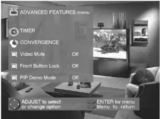
Figure 1. Advanced Features menu.
Convergence Menu
(Figure 2)
Convergence aligns the entire screen at once. Select either Red Convergence or Blue Convergence to begin alignment. To align 64 individual points, see Advanced Convergence, page 39.
Reset Factory Defaults
(Figure 2)
This allows you to reset the convergence to the factory settings. The message "Convergence Reset Completed" will be displayed when the factory defaults have been
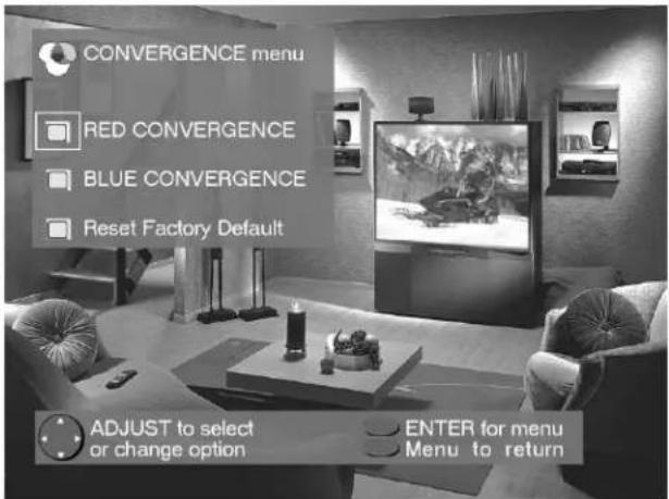
Figure 2. Convergence menu.
Convergence Screen
(Figure 3)
When the Red and Blue crosshairs are properly converged, the center-screen crosshairs will appear white. You can use ▲, ▼, ◀ or ▶ to move the Red and Blue crosshairs. Press VIDEO to switch between Red and Blue. Press AUDIO for the Advanced Convergence screen, and see Advanced Convergence, page 39, for instructions.
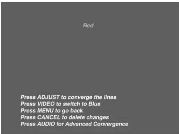
Figure 3. Convergence screen.
Advanced Features Menu: Advanced Convergence and Special Features.

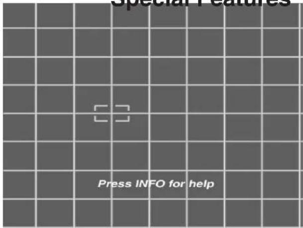
Figure 1. Advanced Convergence screen.
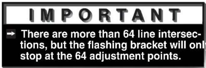
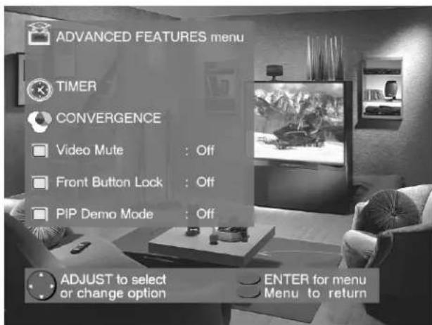
Figure 2. Advanced Features menu.
Advanced Convergence
(Figure 1)
After adjusting the Red Convergence and Blue Convergence, you can fine-tune your TV by adjusting the Red and Blue convergence at 64 individual points. Move the flashing bracket to a position needing adjustment by pressing ▲,▼, ▶r . Press ENTER to select the position (flashing will stop). Move the Red or Blue line by pressing ▲,▼, ▶r . Press VIDEO to switch between the Red and Blue lines. A position is properly converged when all three lines combine to appear white. Press ENTER to deselect the position (flashing will resume), and move the brackets to the next position needing adjustment. When completed, press MENU to save your changes, and exit the Advanced Convergence screen.
Video Mute
(Figure 2)
Video Mute lets you display a blue or black background when no signal is being received on inputs 1-4.
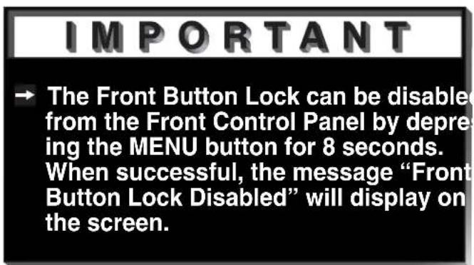
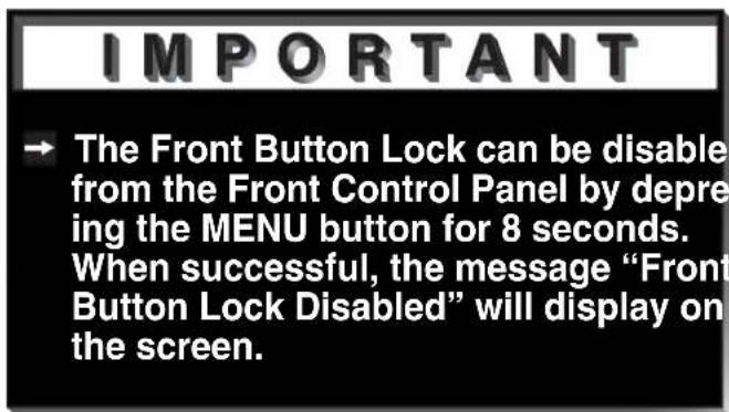
Front Button Lock
(Figure 2)
Front Button Lock lets you disable keys on the front panel to prevent access to TV functions from the front panel.
PIP Demo Mode
(Figure 2)
PIP Demo Mode will demonstrate for you the capabilities of your TV's Picture-In-Picture feature. When set to ON, the TV will cycle through the available PIP formats, wait 2 minutes showing only the main picture, then cycle again. You can stop the PIP demo at any time by pressing the HOME button.

Audio/Video Settings Menu: AV Memory Reset, and Audio/Video Settings
AUDIO/VIDEO SETTINGS menu
(Figure 1)
Each of the television's inputs has its own A/V memory. You can adjust each input's A/V memory in two ways. You can use the menu, or the remote control.
A/V Memory Reset
A/V Memory Reset will return the currently selected input's A/V memory to the factory settings. To reset an input's A/V memory, move to A/V Memory Reset, select the input you want to reset, and press ENTER.
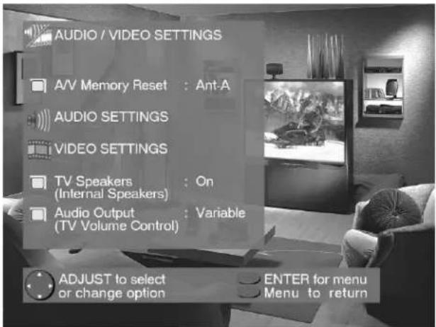
Figure 1. Audio/Video Settings menu.
AUDIO SETTINGS and VIDEO SETTINGS
After selecting AUDIO SETTINGS or VIDEO SETTINGS, you can adjust the settings by pressing ▲,▼, ⬇. For descriptions of the individual A/V settings see A/V Setting Descriptions, pages 42-43.
Using the AUDIO and VIDEO Buttons on the Remote Control
(Figure 2)
1 Press AUDIO or VIDEO to cycle through the available settings.
2 Press ◀ or ▶ to adjust the setting. After 5 seconds of inactivity, the setting display will disappear.
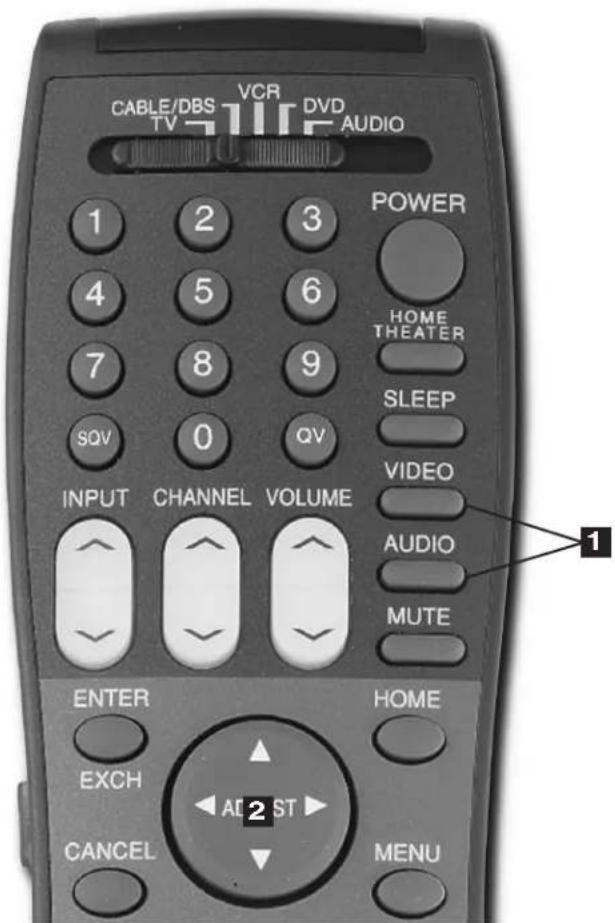
Figure 2. The AUDIO, VIDEO, and ADJUST buttons.
Audio/Video Settings Menu: TV Speakers, and Audio Output

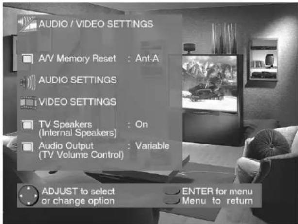
Figure 1. Audio/Video Settings menu.
TV Speakers
(Figure 1)
This selection will turn on or off the TV's internal speakers. You may select Off when sending the sound through a separate stereo system or surround sound A/V receiver.
Audio Output
(Figure 1)
Select Fixed if your audio receiver or stereo system can be controlled with a remote. This allows you to adjust the volume with the system's remote control or the TV remote control, if compatible. This setting is better for surround sound receivers. Select Variable if your audio receiver or stereo system cannot be controlled with a remote. This allows the TV's internal circuitry to adjust the volume.

A/V Setting Descriptions: Audio
Audio Settings
→ Bass enhances or reduces low frequency sound.
Treble enhances or reduces high frequency sound.
Balance adjusts the level of sound between the left and right speakers.
→ Surround creates simulated stereo and surround effects. Your choices are:
- Off: No surround effects. Use this setting when using an A/V receiver with Dolby™ Pro Logic Surround, or Dolby™ Digital Surround.
- Simulated Stereo: Your TV will create a simulated stereo effect when watching a non-stereo program.
- Surround Sound: Your TV will create a simulated surround effect when watching a stereo program.
Listen to (for Ant-A and Ant-B) determines how your TV will receive a broadcast audio signal and play back the sound you hear. Your choices are:
- Stereo: Default setting. The TV will play stereo broadcasts in stereo and mono broadcasts in mono. The word "Stereo" will be displayed when you tune to a channel broadcasting stereo.
- SAP (Second Audio Program): Additional monaural soundtrack that you cannot hear during normal TV viewing. The SAP signal might be related to the program you are watching, such as a soundtrack in a foreign language, or unrelated to the program you are watching, such as a weather report. If a SAP signal is broadcast, the letters “SAP” will be displayed when you tune to the channel.
- Mono: Reduces background noise, and should be used when receiving a weak stereo audio signal. All audio will be played mono with this setting.
→ Listen to (for INPUTs) is not available.
Level Sound automatically equalizes the volume level of programs containing significant level differences from one segment to another (for example, regular Programming to commercials). To receive the best fidelity with music programs, you can turn this setting to Off.
A/V Setting Descriptions: Video

Video Settings
Contrast provides a slider to adjust the white-to-black level. Low contrast shows a variety of shades in darker images, while high contrast shows darker images more uniformly black and makes colors appear more vibrant.
→ Brightness provides a slider to adjust the overall brightness of the picture.
→ Sharpness provides a slider to adjust the detail and clarity.
Tint provides a slider to adjust the proportion of red to green.
→ Color provides a slider to adjust the color intensity.
→ Color Temp (Color Temperature) allows you to adjust how white images are displayed. Your choices are:
- Low 6500K or Low: White images will have a warm cast to them. This adjustment is an average and can vary due to ambient room lighting, video scene brightness and the TV's age. The Low 6500K represents the 6500K industry standard for NTSC pictures.
- Medium: White images will be balanced between the Low (warm) and High (cool) settings.
- High: White images will have a cool cast to them. This setting may provide the most realistic picture under bright lighting.
Video NR (Video Noise Reduction) adjusts the picture noise. When Video NR is ON, you will notice a reduction of video noise and a corresponding reduction in the sparpness of detail. Video NR can improve the appearance of a low quality picture due to a poor signal or older VHS tapes. When Video NR is OFF, there is no change the video noise levels.
Ever wish you were actually part of the movie or sitting in a field-level box at the 50-yard line, watching the game? The Mitsubishi total home theater system is the next best thing to being there. A home theater immerses you in both video and audio to a point of surrealism. The core of the home theater system is your bigscreen television, the biggest one your room can accommodate.

natural_image
Abstract geometric shapes with gradient shading against black background (no text or symbols)Part IV
natural_image
Close-up of a black remote control with various function keys and buttons (no readable text or symbols)
natural_image
Abstract geometric shapes with gradient shading against black background (no text or symbols)Operation
Remote Control Functions..... 46-55
Overview......46
Care and Operation ....47
Channel Selection......48
Sleep Timer 48
System 4 Home Theater
IR Control VS-60719 & VS-70709 49
Special Functions ....54
Operation of PIP...... 50-51
IMPORTANT NOTES ....52
Remote Control Functions: Overview
Overview
(Following page, figure 1)
1 Slide Switch: Select A/V product to be controlled by the remote control.
2 Numbers: Individually select channels or input information into TV.
3 POWER: Turns power on and off for TV and other A/V products.
4 SQV (Super Quick View™): Scan through a memorized list of favorite channels.
5 QV (Quick View™): Switch to last channel viewed.
6 HOME THEATER: (VS-60719 and VS-70709 ONLY) Enables the Home Theater IR System. Once enabled, a press of this key, when in the VCR, DVD, or CableDBS layer, will properly switch the inputs of the AV receiver and the TV so the audio and video automatically coincide.
7 SLEEP: Set the TV to turn off within 2 hours. See Sleep Timer, page 48, for setup instructions.
8 VIDEO: Select the video settings.
9 AUDIO: Select the audio settings.
10 MUTE: Turn sound on or off.
11 INPUT: Select the signal to view (Ant-A, Ant-B, Input-1, Input-2, Input-3, or Component).
12 CHANNEL: Scroll up or down through memorized channels.
13 VOLUME: Change sound level.
14 ENTER/EXCH: Select a channel number or menu item. Exchange PIP and main TV picture.
15 HOME: Exit on-screen menus and return to TV viewing.
16 ADJUST: Navigate menus, change settings, and move the PIP on-screen location.
17 CANCEL: Clear SQV and some menu entries.
18 MENU: Display ▶ViewPoint® on-screen menu system.
19 INFO: Display on-screen summary of the current input used and any broadcast information available (including current V-Chip information).
20 GUIDE: When the slide switch is set to CABLE/DBS, display the on-screen program guide (some cable boxes and DBS receivers).
21 V-CHIP: Enable/Disable the V-Chip Lock.
22 PIP SIZE: Cycle through all available sizes of the PIP feature.
23 PIP INPUT: Select the PIP input source.
24 PIP: Cycle through PIP display choices.
25 PIP CH: Scroll up or down through memorized channels in PIP.
26 REC: Manually record with your VCR.
27 STOP: Stop your VCR, DVD, or CD.
28 PAUSE: Pause your VCR, DVD, CD, or freeze the PIP or POP image.
29 REW/REV: Rewind or reverse search with your VCR, reverse scan with your DVD, or skip reverse with your CD.
30 PLAY: Play your VCR, DVD, or CD.
31 FF/FWD: Fast forward or forward search with your VCR, fast play with your DVD, or skip forward with your CD.
Remote Control Functions: Care and Operation

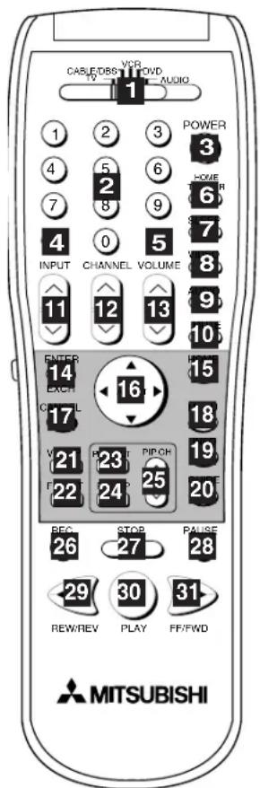
Figure 1. The remote control functions.
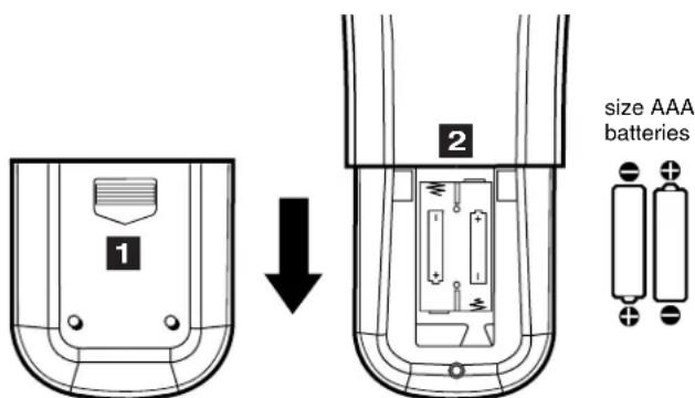
Figure 2. Installing the batteries.
Operation
Installing the Batteries:
(Figure 2)
1 Remove the remote control's back cover by gently pressing the ridged tab in the direction of the arrow and sliding off the cover.
2 Load the batteries, making sure the polarities (+) and (-) are correct.
For Best Results from the Remote Control:
→ Be within 20 feet of the equipment.
Do not press two or more buttons at the same time unless instructed otherwise.
Do not allow to get wet or become heated.
→ Avoid dropping on hard surfaces.
Do not use harsh chemicals to clean. Use only a soft, lightly moistened cloth.
Do not mix new and old batteries.
Do not heat, take apart, or throw batteries into fire.
→ Use only AAA batteries.
Operating the Remote Control:
You can use the remote to control the TV, CABLE/DBS, VCR, DVD, and AUDIO products. Select the product you want to control by moving the slide switch (1 of Figure 1) to the appropriate position. The remote control has been preset to operate the TV and other Mitsubishi products. To program the remote control to operate other products, see Use of the Remote Control with Other A/V Products, pages 24-25.
Remote Control Functions: Channel Selection and Sleep Timer
Channel Selection
→ Enter three numbers (for channel 2, press 002).
or
→ Press the channel number and ENTER (for channel 2, press 2, then ENTER).
or
Enter the channel number and wait four seconds. The TV will change automatically.
Sleep Timer
Setting the Sleep Timer:
→ Press SLEEP on the remote control.
A message indicating the length of time the sleep timer is to be set for is displayed on the TV screen.
Each press of SLEEP will increase the time displayed by 30 minutes, until the maximum value of 120 minutes is reached.
→ After 5 seconds of inactivity, the message will disappear.
Press SLEEP to view the remaining time before the timer turns the TV off.
Canceling the Sleep Timer:
→ Press SLEEP to display the on-screen message.
→ Press SLEEP repeatedly until OFF is displayed.
→ After 5 seconds of inactivity, the message box will disappear.
Remote Control Functions: System 4 Home Theater IR Control
Models VS-60719 and VS-70709
The Mitsubishi System 4 Home Theater IR Control is a special feature that makes it easier to use your TV with a digital surround sound A/V receiver. Once your equipment is properly connected and set up, your TV and digital A/V receiver will change inputs together, to match your selected video input with the corresponding audio input.
When you change inputs on your TV to watch different video products, your TV will send signals via your remote control and the infrared emitters to your digital A/V receiver to change inputs. You will automatically hear the high quality digital surround sound from digital products like your DVD player, and high quality analog stereo or surround sound from non-digital products like your VCR.
Additionally, all IR remote signals from your Mitsubishi remote or other manufacturers remote will be passed through your TV to your A/V devices. Your A/V devices can be hidden or behind cabinet doors and controlled by pointing the remote at the TV.
Remote Control Functions: System 4 Home Theater IR Control
Models VS-60719 and VS-70709

Requirements for Operation
A/V devices connected as described on page 15.
Cable Box connected as on page 16 or Cable Box with an S-Video output connected as on page 19, Connecting an S-Video Device.
TV connected to A/V receiver (TV Monitor Audio Out To A/V Receiver TV Input).
Remote Control programmed to operate your other A/V Devices by System 4 properly activated (see pages 26-27).
→ IR emitters properly connected and placed (see page 20).
IMPORTANT
→ System 4 allows for only one of the following:
- Cable Box
- Satellite Receiver
Operation (VCR as example)
To watch your VCR:
1 Turn on the TV and A/V Receiver.
2 Move slide switch to VCR.
3 Point remote at the TV and press the HOME THEATER button.
4 The TV and A/V Receiver should change to the appropriate inputs.
5 Operate the VCR.
IMPORTANT
→ Other commands from your Mitsubishi remote control, or other manufacturer remote, will be passed through the TV
Remote Control Functions: Special Functions
When your remote control has been Programmed to operate another manufacturer's product, the function performed on each layer can vary. The most common functions are:
| VCR | |||
| POWER PLAYup/downMitsubishi VCRs will be compatible with additional buttons | PAUSE FF/FWDREC STOP | REW/REVCHANNEL | |
| Cable Boxes and Satellite Receivers | |||
| POWERCHANNEL up/down0-9 Number Buttons (on some models) | ENTER (on some models)CANCEL (on some models) | ADJUST up/down/left/right (on some models)GUIDE (on some models) | |
| A/V Receivers | |||
| POWER | VOLUME MUTE | ||
| Mitsubishi A/V Receivers | |||
| Direct Input Selection Buttons -use number buttons, SQV, and QV (on some models) | |||
| Mitsubishi CD Players (not all functions for all models) | |||
| • | • | REW/REVPLAY FF/FWD | STOPPAU |
| DVD and Laser Disc Players (not all functions for all models) | |||
| POWERMENU0-9 Number Buttons (on some models) | PLAY ARROW up/down/left/rightSTOP (on some models) | PAUSEREW/REV | CANCEL (on some models)ENTER |
Remote Control Functions: Operation of PIP
Picture-In-Picture (PIP) features allow you to view Programming in different ways. While watching the main screen, you can display programs from other channels and other inputs. To see which inputs can and cannot be used together, see How Connections Affect the PIP - Table 1, page 14.
Activating the PIP
Figures 1-5 on following page)
Press PIP to choose a display format. With each press of the PIP button on the TV remote control (within 3 seconds of each other), the PIP will cycle through the following display options.
1 PIP
2 Eleven PIP
3 Four PIP
To turn PIP off, wait at least 10 seconds, and press the PIP button. The next time you activate PIP, the last used PIP format will be displayed first.
Remote Control Functions: Operation of PIP
1
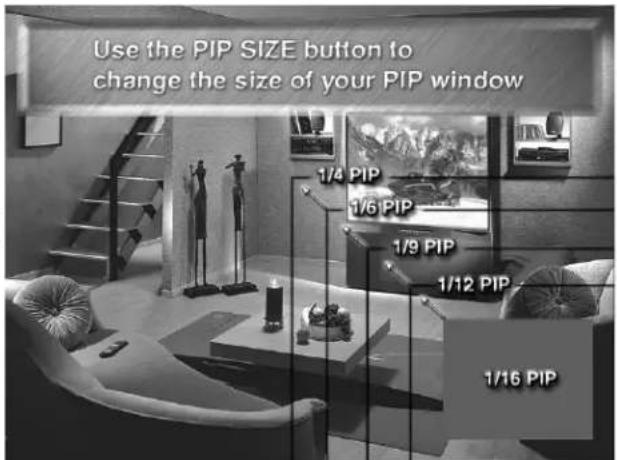
Figure 1. PIP window sizes.
2
natural_image
Interior view of a modern living room with staircase, mannequins, and TV (no visible text or symbols)Figure 2. 11 PIP window sizes.
3
natural_image
Interior scene with a modern living room featuring mannequins, a staircase, and a coffee table (no visible text or symbols)Figure 3. 4 PIP window sizes.
Changing PIP Inputs
Press PIP INPUT to cycle through available inputs. To see which inputs can and cannot be used together, see How Connections Affect the PIP - Table 1, page 14.
Changing PIP Channels
Press PIP CH to scroll up and down through memorized channels on Ant-A, and Ant-B.
Exchanging Program Images
Press ENTER/EXCH to exchange the main picture and the PIP picture.
Moving PIP and Four PIP Image
Press ADJUST ▲,▼, or to move the PIP display anywhere on the main screen, or to select each of the Four PIP locations.
PIP Size (Figure 1)
Press PIP SIZE to cycle through the five sizes available: 14 , 16 , 19 , 112 , and 116 .
Eleven PIP and Four PIP Automatic Switching (Figures 2 and 3)
When viewing either Eleven PIP or Four PIP, the TV will cycle through memorized channels. Press PAUSE to retain the current live video and discontinue automatic switching.
Freeze the PIP
Press PAUSE to freeze the PIP. Press PAUSE again to return to a "live" image.
Main Image Still Frame
When viewing the main image, press PAUSE and a 1/9 PIP window will open with a display of a still frame from the main image. WARNING: See Important Notes, page 21.
PIP Audio Signal
For PIP audio connection illustration, see Back Panel Functions, page 13. Volume for the PIP AUDIO OUTPUT is controlled by the amplifier or wireless headphones.

Warning: Do not leave stationary or letterbox images on-screen for extended periods of time. Mix the types of pictures shown. Uneven picture tube aging is NOT covered by your warranty.
The normal use of a TV should include a mixture of TV picture types. The most frequently used picture types should fill the screen with constantly moving images rather than stationary images or patterns. Displaying the same stationary patterns over extended periods of time, or displaying the same stationary pattern frequently can leave a subtle but permanent ghost image. To avoid this, mix your viewing pattern. Do not show the same stationary image for more than 15% of your total TV viewing in any one week. Display constantly moving and changing images that fill the screen whenever possible.
This projection TV uses picture tubes to project the image onto the screen. All picture tubes age with use. As they age, their light output is gradually reduced. Normal TV pictures fill the screen with constantly changing images. Under these conditions, picture tubes age at an even rate across the entire screen. This maintains a TV picture that is evenly bright over the whole screen. Stationary images or images that only partially fill the screen (leaving black or colored bars to fill the screen), when used over extended periods of time or when viewed repeatedly, can cause uneven aging of the phosphors and leave subtle ghosts of the stationary images in the picture.
Still or stationary images may be received from broadcasters, cable channels, satellite channels, DVD discs, video tapes, laser discs, on-line services, web/internet searching devices, video games, and digital TV tuner/converter boxes. Examples of these types of images can be, but are not limited to the following:
Letterbox top/bottom black bars: shown at the top and bottom of the TV screen when you watch a widescreen (16:9) movie on a standard (4:3) TV.
Side bar images: solid bars shown on each side of an image when watching a standard (4:3) program on a wide-screen (16:9) TV.
Stock-market report bars: ticker running at the bottom of the TV screen.
Shopping channel logos & pricing displays: bright graphics that are shown constantly or repeatedly in the same location.
→ Video game patterns and scoreboards
Bright station logos: moving or low-contrast graphics are less likely to cause uneven aging of the picture tubes.
On-line (internet) web sites: or any other stationary or repetitive computer style images.
Reset System Defaults Instructions Have Been Filed for Future Reference
Reset System Defaults Menu
Reset System Defaults Menu
(Figure 1)
To access the Reset System Defaults menu screen, you must first be out of any active menu screen. You can do this by pressing the HOME button on the remote control. Press the MENU button followed by number buttons 1, 2, and then 3, on the remote control. This sequence will activate the Reset System Defaults menu screen. Pressing the ENTER button on the remote control will reset all option settings back to the factory defaults. Pressing the HOME or MENU buttons on the remote control will remove the Reset System Defaults menu screen and apply no changes to your system settings.
WARNING: Reset System Defaults resets all settings back to the defaults.
To reset system defaults, press the ENTER key. Press HOME or MENU to remove the menu.
Figure 1. Reset System Defaults menu.
IMPORTANT
When the ENTER button on the remote control is pressed, ALL custom setting will be erased and reset to the factory defaults. This operation CANNOT be undone.

Lock Bypass Instructions Have Been Filed for Future Reference
Bypassing the V-Chip Lock
After you set the lock, you need your passcode to view a V-Chip locked program, view the locked TV, cancel the lock, or enter the V-Chip lock menus.
If you forget your passcode, you can view the locked TV without entering your passcode. This is done by pressing the number 9 and QV buttons on the remote TV control at the same time, when your passcode is requested. This process temporarily unlocks the TV.
When entering the V-Chip Lock menu, this process deletes your old passcode and prompts you to enter a new passcode.
IMPORTANT
→ Cut along the dotted line and file bypa instructions in a safe place for future reference.
IMPORTANT
When changing or deleting your passcode, you must use the remote control included with this TV. You cannot use a Mitsubishi remote control from another component or a “univers remote.
55 55
55

Component Input Connection Compatibility
These inputs are compatible with component video signals from standard DVD players and other equipment sending a standard NTSC component video signal (480i).
Input Levels and Timing with Component Video
→ Y =1.0Vp-p (includes sync) 75ohms
Pr =700mVp-p, 75ohms (can also receive signals from outputs labeled R-Y and Cr)
Pb =700mVp-p, 75ohms (can also receive signals from outputs labeled B-Y and Cb)
A/V Receivers
| Mitsubishi . . . . . . . . . . . . . . . . . . . . . . . . . . . . . . . . . . . . . . . . . . . . . . . . . . . . . . . . . . . . . . . . . . . . . . . . . . . . . . . . . . . . . . . . . . . . . . . . . . . . 015 | |
| Admiral . . . . . . . . . . . . . . . . . . . . . . . . . . . . . . . . . . . . . . . . . . . . . . . . . . . . . . . . . . . . . . . . . . . . . . . . . . . . . . . . . . . . . . . . . . . . . . . . . . . | |
| Aiwa. . . . . . . . . . . . . . . . . . . . . . . . . . . . . . . . . . . . . . . . . . . . . . . . . . . . . . . . . . . . . . . . . . . . . . . . . . . . . . . . . . . . . . . . . . . . . . . . . . . . ..220 | |
| Denon . . . . . . . . . . . . . . . . . . . . . . . . . . . . . . . . . . . . . . . . . . . . . . . . . . . . . . . . . . . . . . . . . . . . . . . . . . . . . . . . . . . . . . . . . . . . . . . . . . .234, 235, 236 | |
| Fisher . . . . . . . . . . . . . . . . . . . . . . . . . . . . . . . . . . . . . . . . . . . . . . . . . . . . . . . . . . . . . . . . . . . . . . . . . . . . . . . . . . . . . . . . . . . . . . . . . . . F.204 | |
| Gerrard . . . . . . . . . . . . . . . . . . . . . . . . . . . . . . . . . . . . . . . . . . . . . . . . . . . . . . . . . . . . . . . . . . . . . . . . . . . . . . . . . . . . . . . . . . . . . . . . . . . H.213 | |
| Harman Kardon . . . . . . . . . . . . . . . . . . . . . . . . . . . . . . . . . . . . . . . . . . . . . . . . . . . . . . . . . . . . . . . . . . . . . . . . Jensen . . . . . . . . . . . . . . . . . . . . . . . . . . . . . . . . . . . . JVC . . . . . . . . . . . . . . . . . . . . . . . . . . . . Kenwood . . . . . . . . . . . . . . . . . . . . . . . . . Magnavox . . . . . . . . . . . . . . . . . Marantz. . . . . . . . . . . . . . Mclintosh. . . . . . . . . Nakamichi. . . . . . . Onkyo. . . . . . Optimus. . . . Panasonic. Philips. Pioneer. Quasar RCA Sansui Sharp Sony Sound-sigh TEAC Technics Victor Yamaha. | 21321522323223200208227228224216206217209214203227231230219218221223205207219218221203205227231230203211239234237222238212213210211221218219232233201202 |
DVD Players
| Mitsubishi . . . . . . . .003 |
| Denon . . . . . . . .250 |
| Ferguson . . . . . . .251 |
| GE . . . . . . . .251 |
| JVC . . . . . . . . .257 |
| Normande . . . . . . .251 |
| Panasonic . . . . . .250 |
| Philips/Magnavox .258 |
| Pioneer . . . . . . .252 |
| RCA/Proscan . . . .251, 256 |
| Saba . . . . . . .251 |
| Sony . . . . . .254 |
| Thompson . . . . . .251 |
| Toshiba . . . . . .253 |
| Yamaha. . . . . . .250 |
| Zenith . . . . . .259 |
Satellite Receivers
| MitsubishiHD/Satellite Receiver 006Echostar/Dishnetwork 175GE. . . . . . . . . . . . . . . . . . . . . . . . . . . . . . . . . . . . . . . . . . . . . . . . . . . . . . . . . . . . . . . . . . . . . . . . . . . . . . . . . . . . . . . . . . . . . . . . . . . . . Hitachi. . . . . . . . . . . . . . . . . . . . . . . . . . . . . . . . . . . . . . . . . . . . . . . . . . . . . . . . . . . . . . . . . . . . . . . . . . . . . . . . . . . . . . . . . . . . . . . . . . . Hughes. . . . . . . . . . . . . . . . . . . . . . . . . . . . . . . . . . . . . . . . . . . . . . . . . . . . . . . . . . . . . . . . . . . . . . . . . . . . . . . . . . . . . . . . . . . . . . . . . . . Panasonic. . . . . . . . . . . . . . . . . . . . . . . . . . . . . . . . . . . . . . . . . . . . . . . . . . . . . . . . . . . . . . Philips. . . . . . . . . . . . . . . . . . . . . . . . . . . . . . . . . . . . . . . Primestar. . . . . . . . . . . . . . . . . . . . . . . . . . . . . . . RCA. . . . . . . . . . . . . . . . . . . . . . . Sony. . . . . . . . . . . . . . . . . . . . . . . Toshiba. . . . . . . . . . . . . . . Uniden. . . . . . . . . . . . . . . . . . . . . . . . . . . . . . . . . . . . . . . . . . . . . . . . . . . . . . . . . . . . . . . . . . . . . . . . . . . . . . . . . . . . . . . . . . . . . . . . . . . |
Cable Box
| ABC. . . . . . . . . . . . . . . . . . . . . . . . . . . . . . . . . . . . . . . . . . . . . . . . . . . . . . . . . . . . . . . . . . . . . . . . . . . . . . . . . . . . . . . . . . . . . . . . . . . . . |
| Archer. . . . . . . . . . . . . . . . . . . . . . . . . . . . . . . . . . . . . . . . . . . . . . . . . . . . . . . . . . . . . . . . . . . . . . . . . . . . . . . . . . . . . . . . . . . . . . . . . . . |
VCRs
| Mitsubishi . . . . . . . . . . . . . . . . . . . . . . . . . . . . . . . . . . . . . . . . . . . . . . . . . . . . . . . . . . . . . . . . . . . . . . . . . . . . . . . . . . . . . . . . . . . . . . . . . . . . 062 |
| Admiral . . . . . . . . . . . . . . . . . . . . . . . . . . . . . . . . . . . . . . . . . . . . . . . . . . . . . . . . . . . . . . . . . . . . . . . . . . . . . . . . . . . . . . . . . . . . . . . . . . . |
| Aiwa. . . . . . . . . . . . . . . . . . . . . . . . . . . . . . . . . . . . . . . . . . . . . . . . . . . . . . . . . . . . . . . . . . . . . . . . . . . . . . . . . . . . . . . . . . . . . . . . . . . . A47, 052 |
| Akai . . . . . . . . . . . . . . . . . . . . . . . . . . . . . . . . . . . . . . . . . . . . . . . . . . . . . . . . . . . . . . . . . . . . . . . . . . . . . . . . . . . . . . . . . . . . . . . . . . . Audio Dynamic . . . . . . . . . . . . . . . . . . . . . . . . . . . . . . . . . . . . . . . . . . . . . . . . . . . . . . . . . . . . . . . Bell & Howell . . . . . . . . . . . . . . . . . . . . . . . . . . . . . . . . . . . . . . . . . . . . . . . . . . . . . . . . . . . . . . . . . . . . . . . . . . . . . . . . . . . . . . . . . . . . . . . . . . . . 059, 031 |
| Broksonic . . . . . . . . . . . . . . . . . . . . . . . . . . . . . . . . . . . . . . . . . . . . . . . . . . . . . . . . . . . . . . . . . . . . . . . . . . . . . . . . . . . . . . . . . . . . . . . . . . . ..040, 046 |
| Canon . . . . . . . . . . . . . . . . . . . . . . . . . . . . . . . . . . . . . . . . . . . . . . . . . . . . . . . . . . . . . . . . . . . . . . . . . . . . . . . . . . . . . . . . . . . . . . . . . . . :043, 045 |
| Citizen . . . . . . . . . . . . . . . . . . . . . . . . . . . . . . . . . . . . . . . . . . . . . . . . . . . . . . . . . . . . . . . . . . . . . . . . . . . . . . . . . . . . . . . . . . . . . . . . . . .Craig. . . . . . . . . . . . . . . . . . . . . . . . . . . . . . . . . . . . . . . . . . . . . . . . . . . . . . . . . . . . . . . . . . . . . . . . . . . . . . . . . . . . . . . . . . . . . . . . . . . .. 025, 049, 026 |
| Curtis Mathes. . . . . . . . . . . . . . . . . . . . . . . . . . . . . . . . . . . . . . . . . . . . . . . . . . . . . . . . . . . . . . . . . . . . . . . . . . . . . . . . . . . . . . . . . . . Daewoo. . . . . . . . . . . . . . . . . . . . . . . . . . . . . . . . . . . . . . . . . . . DBX. . . . . . . . . . . . . . . . . . . . . . . . . . . . . . . . . . . . . . . . . . . . . . . . . Dimensia. . . . . . . . . . . . . . . . . . . . . . . . . . Emerson. . . ..023, 038, 039, 040, 045, 046, 062, 063Fisher. 025, 028, 029, 027Funai. 047, 046, 040GE. 057, 065, 044Go Video. 057, 069, 070, 071Goldstar. 026Hitachi. 043, 065, 020Instant Replay. 044, 043Jensen. 059JVC. 059, 030, 031, 054, 076, 077Kenwood. 059, 030, 026, 031LXI. 047, 026, 020, 027, 028, 025, 029Magnavox. 051, 043, 044Marantz. 059, 030, 031Marta. 026Memorex. 044, 029MGA. 058, 060, 067, 068, 061, 062Minolta. 020, 065Multitech. 067, 047, 024NEC. 059, 030, 031, 054Olympic. 044, 043Optimus. 048, 041, 055, 026Orion. 046, 040Panasonic. 043, 044, 041, 042Penney. 044, 020, 065, 025, 059, 030, 031Pentax. 020, 031, 065Philco. 051, 044, 047, 043, 046, 040Phillips. 051, 043, 044Pioneer. 043Proscan. 065, 020, 043, 044, 051, 066, 021, 022Quasar. 041, 042, 043, 044Radio Shack. 053, 044, 025, 056, 029, 060, 047RCA. 053, 065, 020, 043, 044, 049. 051, 066, 021, 022Realistic. 044, 025, 056, 029, 060, 047Samsung. 057, 022, 024, 053Sansui. 059, 046, 040, 072Sanyo. 025, 029Scott. 021, 022, 024, 029, 058, 060, 067, 068, 046, 040Sears. 025, 026, 027, 028, 020Shaintom. 037Sharp. 055, 056Signature 2000. 047, 055Singer. 037Sony. 048, 049, 050, 073, 074, 075SV2000. 047Sylvania. 051, 043, 044, 047Symphonic. 047Tashiro. 026Tatung. 059, 030, 031TEAC. 059, 030, 047, 031Technics. 032, 041, 042, 043, 044Teknika. 044, 047Toshiba. 021, 066Totevision. 026Vector Research. 031Wards. 055, 056, 029, 064, 026Yamaha. 025, 059, 030, 031Zenith. 064 |
Cleaning
Normally, light dusting with a dry, non-scratching duster will keep your TV clean. Use care when cleaning your TV with any other product. If you want to gently wipe down your TV with a lightly moistened soft cloth, first turn off and unplug your TV. You can add a few drops of mild liquid detergent to the water for oily dirt.
DO NOT allow liquid to enter the TV through the ventilation slots.
DO NOT use strong or abrasive cleaners.
DO NOT use spray liquids or cleaners directly on the TV's surface.
DO NOT scrub or rub the TV harshly.
When cleaning the screen behind the Diamond Shield™, wipe GENTLY up and down with the grooves. Do not allow any liquid to drip down the screen into the TV.
Service
If you are unable to correct a problem with your TV, consult your Mitsubishi dealer or a Mitsubishi Authorized Warranty Service Center.
DO NOT adjust any controls other than those described in this Owner's Guide.
DO NOT remove the protective back cover of your TV.
Menus not described and shown in this owner's guide are designed for Factory use and for Authorized Service Personnel. If you see a menu or display not described in this owner's guide, make no changes to the settings, turn off the TV to clear the displays and return to normal operation. Non-authorized changes and changes made by non-authorized persons may void all or part of the warranty.
IMPORTANT
→ DO NOT use any kind of abrasive, liquid or spray cleaner on the surface of the TV screen.
IMPORTANT
d,→ For further assistance, please call (800) 332-2119
| Problem Possible Solution | |
| The TV remote control does not work. Check that the batteries are installed correctly.Check that the selected switch is set to “TV”.Be no further than 20 feet from the TV when using the remote control. | |
| The TV takes several seconds to respond to Press ENTER after a channel number to avoid delays.channel commands. Use the three digit number, i.e 002 for channel 2. | |
| You cannot access a channel. Use number keys instead of CHANNEL up/down.Be sure the channel you want to view is in memory.Check that the TV is turned to the correct input source for that channel, by pressing the INPUT button.Make sure the V-Chip lock is off (page 34). | |
| On-screen displays appear each time you change a function. This is part of normal TV operation. | |
| You cannot program the TV to turn on automatically. The TV may be locked.The clock may not be set. | |
| There is no sound even when the volume is turned up. Check to see if the MUTE button is on.The TV’s “Listen to:” setting may be set to SAP.Check that “TV Speakers” setting is ON. | |
| You have forgotten your lock passcode. See Appendix A, Bypassing the V-Chip Lock, page 59. | |
| PIP does not display a picture.Not all inputs can be displayed as a PIP (page 14). | Make sure the V-Chip lock is off (page 36). |
| The sound does not match the screen picture.If using stereo or A/V reveiver speakers, check input selection on the stereo or A/V receiver.If using stereo or A/V receiver, check that AUDIO is from MONITOR OUTPUT on TV’s back panel. | The TV’s “Listen to:” setting may be set to SAP. |
| There is a large black or gray rectangle on the screen.there is no text information being broadcast. Turn Off in the CAPTIONS menu (page 34). | The TV closed captioning has been set to “text” mode, but |
| You cannot see a picture when you play a VCR tape.button to select the Input source (INPUT-1, INPUT-2, or INPUT-3) that the VCR is connected to. | If you connected your VCR with A/V cables, use the INPUTCheck your VCRs owner’s guide for further troubleshooting. |
| V-Chip Lock is not working | Make sure that V-Chip is On (page 36).If V-Chip Hours/Lock by Time is currently set to disable the V-Chip lock, the V-Chip will not block programing. |
A
adding and deleting channels 36
Advanced Features menu 37
adjusting (convergence) 38-39
alignment (convergence) 38-39
antennas (connecting) 16
assistance 6, 22, 59
audio settings 42
audio output 13, 30, 40-41
B
back panel 13
balance 42
bass 42
blocking (enabling V-Chip) 33-35
brightness 43
bypassing (parental lock) 55
C
cleaning 4, 59
Clock (setting) 31
compatibility (signal) 57
contrast 43
convergence 38-39
closed captions 32
D
date (setting) 31
daylight savings time (DST) 31
dusting 59
E
español 29, 31
EXCH button on remote 46
F
front control panel 12
Front Button Lock 39
G
games 21, 52
ghost 21, 53
I
IMPORTANT NOTES 23, 58
Important Safeguards 4-5
IR Emitter Home Theater (System 4)
activation 26-27
connection 14-15, 20
special setups 15
remote control functions 46-47
L
language 29, 31
locked 33-35, 55
M
maintenance 2, 59, 63
memorize channels 31
memory (channel) 36
multibrand remote 24-25
N
naming channels 36
naming inputs 26, 36
noise reduction (Video NR) 43
P
passcode 33, 35, 55
Picture-in-Picture (PIP)
Demo Mode 39
Setup 14
Operation 50-51
Q
Quick View™ (QV) 46
R
remote control
audio settings 42
care and operation 47
channel selection 48
functions 46-51
installing batteries 47
multibrand remote 24-25
programming codes, 26-27, 62
replacement, 6
Sleep Timer, 52
reset (A/V Memory), 12, 42
S
safeguards, 4-5
servicing, 2, 5, 63
signal types
1080i, 56, 61
480i, 41, 61
480p (progressive DVD), 41, 61
720p, 61
960i, 41
Sleep Timer, 52
sound (adjusting), 46
Spanish, 33
Special Functions, 54
SQV (Super Quick View™), 35
stand, 4
STATIONARY PICTURE
WARNING, 19, 23, 58
surface, 4, 63
surges, 5
ratings and categories, 37
signal information, 37
ventilation, 4, 63
Video Display, 41
Video Mute, 41
Video Settings, 47
W
Mitsubishi Limited Warranty, 67
T
time (setting), 44-45
Hours/Lock by Time, 38
passcode setting, 36
MITSUBISHI PROJECTION TELEVISION LIMITED WARRANTY
MITSUBISHI DIGITAL ELECTRONICS AMERICA, INC. ("MDEA") warrants to the original purchaser of this television that if purchased from an authorized MITSUBISHI Audio/Video Dealer, should it prove defective by reason of improper workmanship and/or material:
a. Parts. The lenticular (i.e. front picture) screen and/or the DiamondShield™ is warranted against defects in materials and workmanship for a period of 30 days. All other parts are warranted for a period of one year from the date of the original purchase at retail. We will repair or replace, at our option, any defective part without charge for the part. Parts used for replacement are warranted for the remainder of the original warranty period.
b. Labor. For 30 days after the original purchase at retail, we will repair or replace, at our option, the lenticular screen if it proves defective. For all other parts, we will provide the labor for a warranty repair by an authorized MITSUBISHI service center without charge for one year from the original date or purchase at retail.
c. Notice. To obtain warranty service, you must notify an authorized MITSUBISHI service center of any defect within the applicable warranty time period.
- TO OBTAIN WARRANTY SERVICE:
a. Contact your nearest authorized MITSUBISHI service center whose name and address can be obtained from your MITSUBISHI dealer or by writing or calling MDEA at the address and telephone number provided below.
b. Warranty service will be provided in your home or, if required, at an authorized service shop, provided that your television is located within the geographic territory customarily covered by an authorized MITSUBISHI service center. If not, you must either deliver your television to an authorized service location at your own expense, or pay for any travel and/or transportation costs the service center may charge to and from your home. Actual service labor will be provided without charge.
c. Proof of purchase date from an authorized MITSUBISHI dealer is required when requesting warranty service. Present your sales receipt or other document which establishes proof and date of purchase. THE RETURN OF THE OWNER REGISTRATION CARD IS NOT A CONDITION OF WARRANTY COVERAGE. However, please return the Owner Registration Card so that we can contact you should a question of safety arise which could affect you.
2. THIS WARRANTY DOES NOT COVER damage caused by: modification, alteration, repair or service of the product by anyone other than an authorized MITSUBISHI service center; physical abuse to, or misuse of, the product; operation in a manner contrary to the instructions which accompany the product, including uneven picture tube aging and imprinted images on the viewing screen; freight damage; or any damage caused by acts of God such as lightning or fluctuation in electrical power. This warranty also excludes all costs arising from installation, adjustment of user controls, external antenna systems, service of products purchased or service outside the U.S.A., initial technical adjustments (set-up) and user-required maintenance. Consult the operating instructions furnished with the product for information regarding user controls.
3. ANY EXPRESS WARRANTY NOT PROVIDED HEREIN, AND ANY REMEDY WHICH, BUT FOR THIS PROVISION, MIGHT ARISE BY IMPLICATION OR OPERATION OF LAW, IS HEREBY EXCLUDED AND DISCLAIMED. THE IMPLIED WARRANTIES OF MERCHANTABILITY AND FITNESS FOR ANY PARTICULAR PURPOSE ARE EXPRESSLY LIMITED TO A TERM OF ONE YEAR.
4. UNDER NO CIRCUMSTANCES SHALL MDEA BE LIABLE TO PURCHASER OR ANY OTHER PERSON FOR ANY INCIDENTAL, SPECIAL OR CONSEQUENTIAL DAMAGES, WHETHER ARISING OUT OF BREACH OF WARRANTY, BREACH OF CONTRACT, OR OTHERWISE.
5. Some states do not allow limitations on how long an implied warranty lasts, or the exclusion or limitation of incidental, special or consequential damages, so the above limitations or exclusions may not apply to you.
6. This warranty gives you specific legal rights, and you may also have other rights which vary from state to state.
7. BEFORE REQUESTING SERVICE, please review the instruction booklet to insure proper installation and correct customer control adjustment. If the problem persists, contact your nearest MITSUBISHI Dealer for the name(s) of authorized MITSUBISHI Service Center(s). If you are unable to obtain this information, please call 800-332-2119, or write us at the address below.
MITSUBISHI DIGITAL ELECTRONICS AMERICA, INC.
9351 Jeronimo Road
Irvine, CA 92618-1904

MITSUBISHI
RETAIN THIS PORTION FOR YOUR RECORDS
SERIAL NO.
MODEL NO.
DEALER NAME
STREET ADDRESS
CITY_STATE_ZIP
PHONE ( ) PURCHASE DATE
If you have questions regarding your television, call Consumer Relations at
(800) 332-2119, or email us at MDEA service@bigscreen.mea.com
To order replacement or additional remote controls or owner's guides
call (800) 553-7278
or
visit our website at www.mitsubishi-v.com