
MP8740 - Video projector 3M - Free user manual and instructions
Find the device manual for free MP8740 3M in PDF.


| Product Type | Multimedia Projector |
| Model | MP8740 |
| Display System | 3-beam poly-silicon LCD |
| Panel Size | 1.3 inches per panel (33 mm) |
| Native Resolution | XGA (1024 x 768) per panel, 2.36 million total pixels |
| Lens | F/2.3 - F/3.0, focal length 48.1 - 72.1 mm |
| Lamp | Metal halide 260 W |
| Speaker Output | 2 x 2W stereo |
| Power Supply | AC 100-120V / 220-240V (universal) |
| Power Consumption | 370 W |
| Dimensions (W x H x D) | 404 x 154 x 305 mm (15.9 x 6.1 x 12.0 in) |
| Weight | 8.4 kg (18.6 lbs) |
| Operating Temperature | 32°F - 95°F (0°C - 35°C) |
| Video Inputs | S-Video (Mini DIN4), composite (RCA), Audio L/R (RCA) |
| RGB Inputs | 2 x D-sub 15-pin (RGB1, RGB2) |
| Outputs | RGB (D-sub 15-pin), Audio (stereo mini jack) |
| Control Interfaces | RS-232, PS/2, ADB, Serial mouse, Remote control (IR) |
| Special Features | Power zoom/focus, fixed keystone correction, image mirroring, 7-language OSD, laser pointer remote, Kensington lock |
| Warranty | 2 years parts and labor |
| Accessories Included | Remote control with batteries, power cord, VGA cable, video/audio cable, S-Video cable, mouse cables (PS/2, ADB, Serial), stereo mini jack |
| Maintenance | Clean air filter every 50 hours; lamp replacement after approx. 2000 hours |
Frequently Asked Questions - MP8740 3M
User questions about MP8740 3M
0 question about this device. Answer the ones you know or ask your own.
Ask a new question about this device
Download the instructions for your Video projector in PDF format for free! Find your manual MP8740 - 3M and take your electronic device back in hand. On this page are published all the documents necessary for the use of your device. MP8740 by 3M.
USER MANUAL MP8740 3M
natural_image
Line drawing of a 3M MP8740 projector with control panel and display screen (no text or symbols on body)Safeguards 1
Warranty 2
Section 1: Unpack ....3
1.1 Contents of Shipping Box 3
1.2 Optional Accessories 3
1.3 Keep Your Packing Materials .... 3
1.4 What's Next? 3
Section 2: Product Description ....4
2.1 Machine Characteristics 4
2.2 Part Identification List 4
2.3 System Setup.... 5
2.4 Remote Control Transmitter Identification 6
Section 3: Basic Operations....7
3.1 Projector Startup 7
3.2 Projector Shutdown 7
Section 4: Adjustments and Functions......8
4.1 Menu Navigation 8
4.2 How To Use Height Adjustment Feet 9
4.3 SETUP 10
4.4 INPUT 11
4.5 IMAGE 12
4.6 OPT 13
Section 5: Maintenance....14
5.1 Cleaning the Air Filter 14
Section 6: Lamp....15
6.1 Lamp 15
6.2 Display Lamp Operation Hours.... 15
6.3 Replacing the Lamp 15
Section 7: Troubleshooting ....17
7.1 Sympton/Solution Table 17
7.2 Message/Solution Table 17
Section 8: Accessories .... 18
8.1 Service Information 18
Appendix: Technical Information......A.1
INTENDED USE
Before operating the machine, please read the entire manual thoroughly. The 3M ™ Multimedia Projector 8740 was designed, built and tested for use indoors, using 3M ™ brand lamps and nominal local voltages. The use of other replacement lamps, outdoor operation or different voltages has not been tested and could damage the projector or peripheral equipment and/or create a potentially unsafe operating condition.
IMPORTANT SAFEGUARDS
- Read and understand all instructions before using.
Pay particular attention to areas where this ⚠ symbol is shown.

WARNING - Indicates a potentially hazardous situation which, if not avoided, could result in death or serious injury.
Caution - Indicates a potentially hazardous situation which, if not avoided, could result in minor or moderate injury. It may also be used to alert against unsafe practices.
-
Close supervision is necessary when any appliance is used by or near children. Do not leave appliance unattended while in use.
-
Never look directly into the projector lens when the lamp is on. The metal halide lamp produces a strong light which could damage your eyesight.
-
Care must be taken as burns can occur from touching hot parts.
-
Do not operate appliance with a damaged cord or if the appliance has been dropped or damaged – until it has been examined by a qualified service technician.
-
Position the cord so that it will not be tripped over, pulled, or contact hot surfaces.
-
If any extension cord is necessary, a cord with a current rating at least equal to that of the appliance should be used. Cords rated for less amperage than the appliance may overheat.
-
Always unplug appliance from electrical outlet before cleaning and servicing and when not in use. Grasp plug and pull to disconnect.
-
To reduce the risk of electric shock, do not immerse this appliance in water or other liquids.
-
To reduce the risk of electric shock, do not disassemble this appliance, but take it to a qualified technician when service or repair work is required. Incorrect assembly can cause electric shock when the appliance is subsequently used.
-
Connect this appliance to a grounded outlet.
-
Do not expose this projector to direct sunlight, or use it outside.
-
Keep all ventilation openings free of any obstructions.
-
Always open the lens shutter when the projection lamp is on.
-
Do not look directly into light beam of laser pointer. The pointer produces a strong light which could damage your eyesight.
-
The projection lamp contains mercury. Always dispose of it in a proper manner according to local regulations.
SAVE THESE INSTRUCTIONS
The information contained in this manual will help you operate and maintain your 3M MP8740 Multimedia Projector.
THANK YOU FOR CHOOSING 3M
Thank you for choosing 3M Multimedia Projector equipment. This product has been produced in accordance with 3M's highest quality and safety standards to ensure smooth and trouble free use in the years to come.
For optimum performance, please follow the operating instructions carefully. We hope you will enjoy using this high performance product in your meetings, presentations and training sessions.
LIMITED WARRANTY
3M warrants this product against any defects in material and workmanship, under normal usage and storage, for a period of two years from date of purchase. Proof of purchase date will be required with any warranty claim. In the event this product is found to be defective within the warranty period, 3M's only obligation and your exclusive remedy shall be replacement of any defective parts (labor included).
To obtain warranty service, immediately notify the dealer from which you purchased the product of any defects. In the USA call 1-800-328-1371 for warranty or repair service.
LIMITATION OF LIABILITY
THE FOREGOING WARRANTY IS MADE IN LIEU OF ALL OTHER WARRANTIES, EXPRESSED OR IMPLIED, AND 3M SPECIFICALLY DISCLAIMS ANY IMPLIED WARRANTY OF MERCHANTABILITY AND FITNESS. 3M SHALL NOT BE LIABLE FOR ANY DAMAGES, DIRECT, CONSEQUENTIAL, OR INCIDENTAL, ARISING OUT OF THE USE OR INABILITY TO USE THIS PRODUCT.
Important: The above warranty shall be void if the customer fails to operate product in accordance with 3M's written instructions. This warranty gives you specific legal rights and you may have other rights which vary from state to state.
FCC STATEMENT - CLASS A: This equipment generates, uses and can radiate radio frequency energy, and if not installed and used in accordance with the instruction manual may cause interference to radio communications. It has been tested and found to comply with the limits for a Class "A" computing device pursuant to Subpart B of Part 15 of the FCC Rules, which are designed to provide reasonable protection against such interference when operated in a commercial environment. Operation of this equipment in a residential area is likely to cause interference in which case the user at his/her own expense will be required to take whatever measures may be required to correct the interference.
EEC STATEMENT: This machine was tested against the 89/336/EEC (European Economic Community) for EMC (Electro Magnetic Compatibility) and fulfills these requirements.
Video signal cables: Double shielded coaxial cables (FCC shield cable) must be used and the outer shield must be connected to the ground. If normal coaxial cables are used, the cable must be enclosed in metal pipes or in a similar way to reduce the interference noise radiation.
Video inputs: The input signal amplitude must not exceed the specified level.
IBM is a registered trademark of International Business Machines Corporation. Apple Macintosh and Apple Powerbook are registered trademarks of Apple® Computer, Inc. Microsoft and Windows 95 are registered trademarks, and Windows and Windows for Work Groups are trademarks of the Microsoft Corporation. Toshiba is a registered trademark of Toshiba Corporation. Kensington is a trademark of Kensington Corporation. All other products are trademarks or registered trademarks of their respective companies.
1.1 Contents of Shipping Box
The 3M ™ MP8740 Multimedia Projector is shipped with the necessary cables required for standard VCR, PC, MAC ™ II or laptop computer connections. Carefully unpack and verify that you have all of the items shown below in Figure 1.1.

natural_image
Line drawing of a 3M projector with no visible text or symbolsMP8740 Multimedia Projector
Remote Control Transmitter (batteries included)

Power Cord
110V - US
220 - UK, Europe
3-Conductor Video/Audio Cable

VGA Cable (15-15 pin M/M)

Adapter with dip switch

Video Cable
(S-Video mini DIN4-pin)
Figure 1.1 Inventory of Shipping Box
The shipping carton contains the items illustrated in Figure 1.1. In addition, the following items are also included, but not shown here. If any of these items are missing, please contact your place of purchase.
- PS/2 mouse cable ...... (1)
- ADB mouse cable ...... (1)
- Serial mouse cable ...... (1)
- Stereo mini-jack ...... (1)
1.2 Optional Accessories
• RS-232 control cable ..... (1)
1.3 Keep Your Packaging Materials
√ Important
Save the shipping box and packing materials in the event the MP8740 should require shipping to a 3M Service Center for repair.
1.4 What Next?
After you have unpacked the MP8740 system and identified all the parts, you are ready to set up the projector.
2.1 Machine Characteristics
The MP8740 Multimedia Projector integrates metal halide lamp and polysilicon LCD display technology into a single unit. It accepts input from two different computer sources and two video/audio sources and projects a bright, super crisp image. Switching your presentation from a computer input to a video input, and then back to a computer input simply requires the push of a button on the remote control keypad or control panel keypad.
The MP8740 Multimedia Projector offers the following features:
• Metal halide projection lamp
• XGA resolution (3 separate 1024 x 768 LCD panels are used for the R, G and B signals)
- Advanced SXGA scaling (60 Hz and 75 Hz)
- Advanced VGA and SVGA scaling
- Compact size, light weight for portability
- RGB (computer video) output terminal
- Serial, PS/2 and Apple© Desktop Bus (ADB) mouse emulation
• Power zoom and power focus functions
- Easy to set up and use
- Ability to display 16.7 million colors
- Two computer input connections
- Two video input connections (composite and S-video compatible)
• Full function remote control
- Two built-in stereo speakers (2 watts each)
• Horizontal and vertical image inverting function
• Horizontal and vertical image position control
• Fixed keystone correction
- On screen menu with seven languages
• Universal power supply
- IR sensor in front and rear for maximum remote control range
• RS-232 control capability
- Optional ceiling mount kit
- Laser pointer (remote control)
• Color balance control for data/video
- Kensington™ lock

√ Note
The MP8740 is one of the brightest projectors in the marketplace. The brightness of your machine will vary depending on the ambient room conditions and contrast/brightness settings.
2.2 Part Identification List

Figure 2.1 Identifying MP8740 Parts
- Remote control transmitter
- Stereo speakers
- Control Panel Keypad
a) STAND BY/ON button
b) ON, LAMP, TEMP, Indicator
c) INPUT, MUTE, RESET buttons
d) ZOOM, FOCUS, MENU buttons - Remote Control Sensors (front/back)
- Terminal Connection Panel
a) S-Video, Vidoe, Audio inputs
b) RGB1 and RGB2 inputs
c) RGB output
d) Audio L/R input, Audio output (stereo mini jack)
e) RS-232 Control
f) AC input-power cord connection
g) Main power switch
h) Kensington™ lock
-
Height Adjustment Feet
-
Lens shutter (open/closed)
-
Projection lens
-
Cooling fan exhaust
-
Carry handle
2.3 System Set Up - connecting various equipment

flowchart
graph TD
    A["Laser Disc"] --> B["WHT RED"]
    B --> C["OUT OUT OUT"]
    C --> D["Audio Right"]
    D --> E["Audio Left"]
    E --> F["S-VHS"]
    F --> G["IN IN IN"]
    G --> H["MP8740"]
    H --> I["MAC or PC"]
    I --> J["OUT"]
    J --> K["Laptop"]
    L["VCR"] --> M["OUT OUT OUT"]
    M --> N["Audio L/R Video"]
    N --> O["IN IN IN"]
    O --> P["Power"]
    P --> Q["MAC or PC"]
    Q --> R["PC"]
    S["CRT Display"] --> T["MAC or PC"]
    U["MONITOR PORT"] --> V["MONITOR PORT"]
    W["PS/2 or SERIAL PORT"] --> X["MONITOR PORT"]
    Y["POWER"] --> Z["MAC or PC"]
Figure 2.2 Cable Connections
| Caution |
| Turn power off to all devices before making connections. Never plug anything into the projector or computer while any device is in operation.The MP8730 must be powered down when making connections. The mouse emulation may not work if the unit is not powered down before the mouse cable connections are made. |
2.3.1 Apple™ Desktop Mouse - The Macintosh operating system should recognize the MP8740 as a mouse without any drivers being loaded.
VirtualMouse for PC Computer - For IBM™ compatible computers, the operating systems will need to be set to "Serial Mouse" or "PS/2 Mouse" to recognize the projector as a mouse pointer device
Change mouse driver information to "Serial Mouse" or "PS/2 Mouse."
a) Windows™ 95 - Click "Start"; select "Settings"; select "Control Panel". Click on "Mouse"; select the "General" tab; (see what driver is currently loaded and make note of it); select "Change"; select "Show all devices"; (make note of the current Manufacturer and Model); select "Standard Mouse Type" for Manufacturer; then select "Standard Serial Mouse" or "Standard PS/2 Mouse." Click OK to change and apply the new driver. Restart Windows when prompted.
b) Windows ™ 3.1 - From "Program Manager" click "Main"; then click "Windows Setup", (make note of what the current mouse driver is); Click "Options"; then "Change Systems Settings". Choose "Mouse". It should be listed as "Microsoft or IBM PS/2".
√ Note
For proper mouse operation, always turn the projector power on first and then power up the computer.
For some laptop computers you may need to disable the internal pointing device (IPD). This is done through the BIOS level set up of the particular machine, or it could be listed in a "Utilities" program group, i.e., "Toshiba Utilities™," or "Thinkpad Features™."
2.4 Remote Control Transmitter Identification
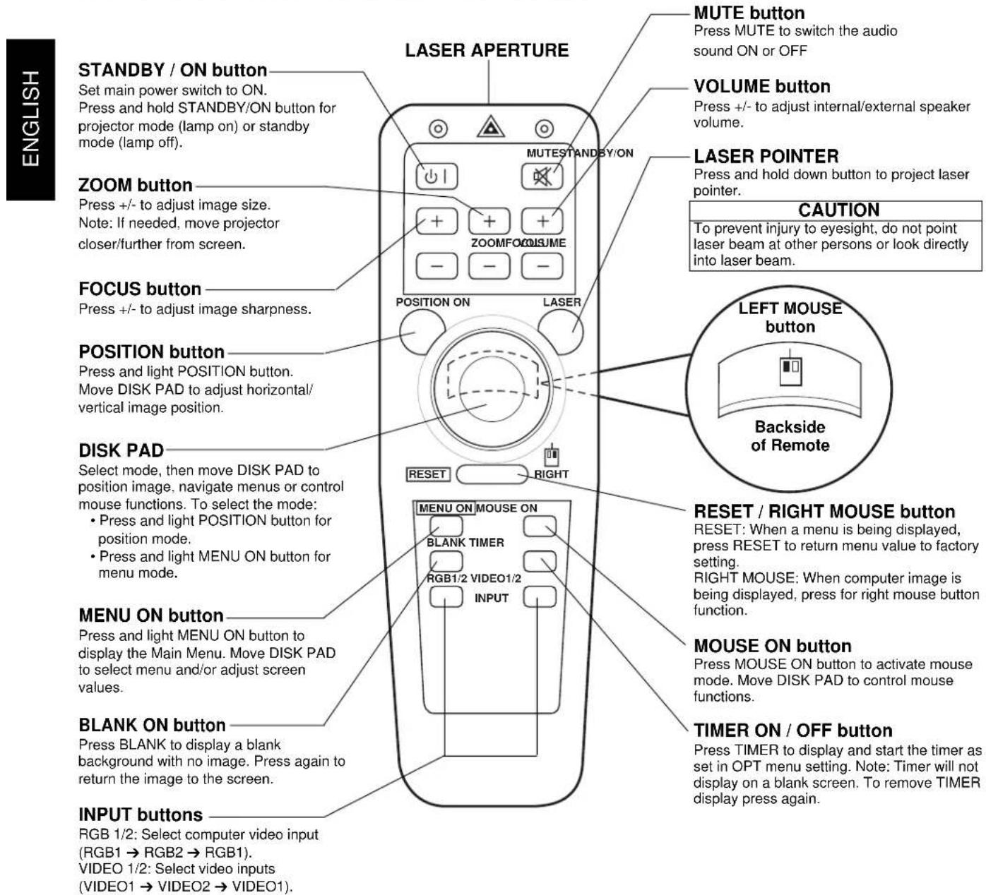

Figure 2.3 Remote Control Buttons
3.1 Projector Startup

Figure 3.1 Projector Controls
- Make all cable connections and line hookups with the power off.
- Turn the POWER SWITCH 1/O of the projector on. The ON indicator will light up orange.
- Move the LENS SHUTTER CONTROL to the open position.
- Press the STANDBY/ON button Ⓞ. The ON indicator blinks (green) and then lights (green). The ON indicator will blink green during warm-up and lamp ignition.
- Adjust the screen size using the ZOOM button
- Adjust the focus using the FOCUS button
A) Press the FOCUS button. The on-screen display shown on the right appears. B) Adjust the focus so that the picture is sharp using the FOCUS button.
-
Turn on all connected equipment. The method of connecting various equipment, see section 2.3.
-
Press the INPUT button ☐ on the projector or the INPUT SELECT (VIDEO or RGB) button on the remote to select the source of the signal to be projected on the screen. The selected signal input is displayed at the bottom right of the screen. The display will show the last selected input source before power was turned off.
3.2 Projector Shutdown
- Hold the STANDBY/ON button ⏻ for 3-5 seconds. The ON indicator blinks orange and the lamp turns off. After approximately 1 minute, the fan stops and the indicator stays orange.
- Turn the MAIN POWER SWITCH 1/0 of the projector off.
Caution
Do not turn off the POWER SWITCH before pressing the STANDBY/ON button. After the STANDBY/ON button is pressed, the fan rotates for about 1 minute to cool the projector.
-
Close the LENS SHUTTER Push up on the lens cover switch to close.
-
Disconnect cables.
4.1 Menu Navigation

Figure 4.1 Menu Button
- Press the MENU button on projector or remote control MENU button.
On-screen menus are displayed on the screen.
- Select the menu to be adjusted using the MENU ( ◀ ▶ ) buttons or DISC PAD.
Selected Menu is highlighted.
- Select the item to be adjusted using the MENU ( ▲ ▼ ◀ ▶ ) buttons or DISC PAD.
Highlighted items may be adjusted.
√ Note
Separate settings are provided for the VIDEO1, VIDEO2, RGB1 and RGB2 input terminals. Adjustments are saved after power off.
Factory Default Setting:
-
Highlight SETUP option.
-
To reset the entire SETUP menu
- Press the RESET button.
- Select DEFAULT or CANCEL.
- To reset a single item from SETUP menu
- Select the adjustment item (brightness, contrast...)
- Press the RESET button. Only the selected item resets.

Figure 4.2 Default Settings
4.2 How To Use Height Adjustment Feet
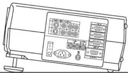
Adjust the image elevation using the height adjustment at the front of the projector.
- Move the lock lever to the unlock position.
- Extend or retract each foot to the desired height.
- Move the lock lever to the lock position.
-
For fine adjustments, rotate each foot.
-
Raise the front end of the projector so the feet are not touching the table top.
| Caution |
| Do not unlock the foot adjusters if the projector is not supported. If the foot adjusters do not lock completely, turn the foot adjusters slightly before locking. |
Front view
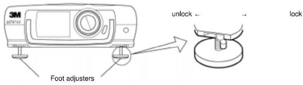
Side view
natural_image
Line drawing of a device front panel with buttons and ports (no readable text or symbols)Figure 4.3 Height Adjustment
4.3 SETUP
The SETUP sub-menu is used to adjust and move the image position. The projector will display either the RGB (Figure 4.4) or Video (Figure 4.5) menu according to the input source being projected.
RGB signal input Video signal input


Figure 4.4 RGB Signal Figure 4.5 Video Signal
| Adjustment Item | Details of adjustment | Default |
| VOLUME | Decrease Increase→ | |
| BRIGHT (BRIGHTNESS) | Dark Bright→ | |
| CONTRAST | Lower ←→ Higher | |
| SHARPNESS | Soft ←→ Sharp | |
| COLOR | Less ←→ More | |
| TINT | Red ←→ Green | |
| V.POSIT (V.POSITION) | Moves the picture up or down. | —— |
| H.POSIT (H.POSITION) | Moves the picture left or right. | —— |
| H.PHASE | Decreases the picture flicker | —— |
| H.SIZE | Widens or Narrows the horizontal size of picture | —— |
| COLOR BAL | Red ←→ Blue |
√ Note
- TINT cannot be adjusted with a PAL or M-PAL video signal input.
• TINT, COLOR and SHARPNESS cannot be adjusted with an RGB signal input.
• V. POSIT, H. POSIT, H. PHASE and H. SIZE cannot be adjusted with a VIDEO signal input.
4.4 INPUT
The menu INPUT sub-menu (Figure 4.6) is used to select the input source. The VIDEO1 and VIDEO2 values (Figure 4.7) have additional values that can be selected.

Figure 4.6 Input Menu Figure 4.7

flowchart
graph TD
    A["RGB1"] --> B["VIDEO1"]
    C["RGB2"] --> B
    D["VIDEO2"] --> E["VIDEO2"]
    F["TEST"] --> G["PATTERN"]
    H["SYSTEM"] --> I["AUTO"]
    H --> J["NTSC"]
    H --> K["PAL"]
    H --> L["SECAM"]
    H --> M["NTSC 4.43"]
    H --> N["M-PAL"]
| Adjustment Area | Value | Value Screen | Value |
| RGB1 | Selects the RGB1 terminal | ||
| RGB2 | Selects the RGB2 terminal | ||
| Video1 | Select the VIDEO1 orVIDEO2 terminal | System | Selects the video signal format Auto, NTSC, PAL, SECAM, NTSC 4.43, M-PAL |
| Video2 | |||
| Test Pattern | Selects the TEST PATTERN.(Start up Screen) |
4.5 IMAGE
The IMAGE sub-menu is used to change the image characteristics.
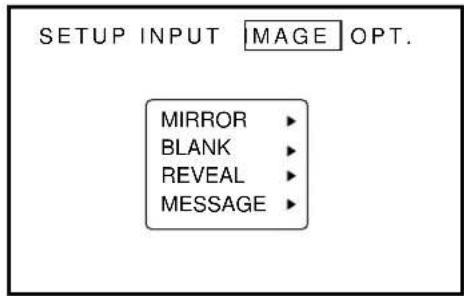
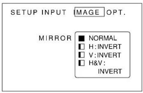
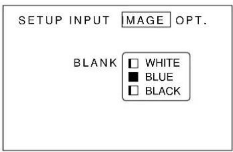


Figure 4.8 Image Adjustment Screens
| Adjustment Screen | Value |
| MIRROR | Inverts the picture horizontally or vertically.H : INVERT Inverts the picture horizontally.V : INTERT Inverts the picture vertically.H&V: INVERT Inverts the picture horizontally and vertically. |
| BLANK | Selects the blank color. |
| REVEAL | Selects reveal speed. |
| MESSAGE | Turn ON or OFF on-screen messages. |
4.6 OPT
The OPT. sub-menu allows you to control communication function.

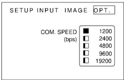


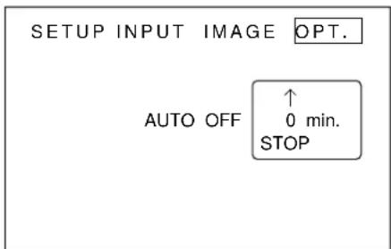

Figure 4.9 OPT Adjustment Screens
| ADJUSTMENT SCREEN | VALUE DEFAULT | |
| COM. SPEED | Selects the data speed of transmission. (For mouse emulation-1200) 1200 | |
| COM. BITS 7N1... 7 data-bits, No parity, 1 stop bit. (For mouse emulation-7N1) 7N18N1... 8 data-bits, No parity, 1 stop bit. | ||
| TIMER Sets the timer (in minutes). — | ||
| LANGUAGE | Selects the language on-screen menu. —(English, French, German, Spanish, Italian, Norwegian, Dutch) | |
| AUTO OFF Selects how long projector will stay on, if no input is detected. —Select 0 to disable this function. | ||
| START UP Enable/Disable Startup Screen. TURN ON | ||
5.1 Cleaning the Air Filter
√ Note
Clean the air filter about every 50 hours.
- Turn off the MAIN POWER switch of the projector and pull out power cord. Let cool for 20 minutes.
- Remove the air filter from the bottom of projector. Unscrew two retaining screws (1) and pull down and out (2) on the handle to free air cleaner door. Lift air filter door up and out (3) and set it aside.
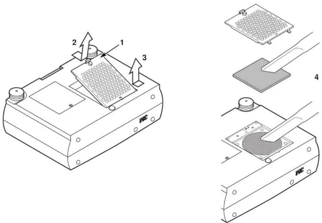
Figure 5.1 Remove Air Filter
- Carefully remove foam air filter Screen (4) and clean foam screen and metal screen using a vacuum cleaner.
- Re-install the air filter and replace the air filter door.
√ Note
If air flow is restricted due to dust accumulation on filter, the projector may shut down due to over heating.
6.1 Lamp
The following symptoms may indicate a lamp in need of replacement:
• LAMP indicator lights up red.
- "CHANGE THE LAMP" message appears on the screen.
6.2 Display Lamp Operation Hours
To determine the lamp operation hours, follow these steps:
- While the projector is running, press and hold the timer button on the remote control for 3 seconds.
- The operating time of the lamp will be displayed. If the operating hours are greater than 1,900 the "CHANGE THE LAMP" message will appear. If the hours are greater than 1,980 the following message will appear, "POWER WILL SHUT OFF IN 20 HOURS" The number of hours left until shut down will decrease until 0 hour is reached, then power will be turned off.
√ Note
After 2000 hours, the projector will only run for 10 minute intervals when restarted until the lamp is replaced and the lamp timer is reset. The message "CALL A MAINTENANCE PERSON" will blink at projector start up to remind you to change the lamp.
- To reset the timer, press the reset button and select 0 (or CANCEL). The "CHANGE THE LAMP" message will not come up if the timer is reset.
6.3 Replacing the Lamp
WARNING
Always turn off and unplug projector when changing lamp.
Lamp and adjacent metal parts become extremely hot and can cause severe burns to your fingers. Allow the projector to cool for at least 30 minutes before replacing the lamp.
-
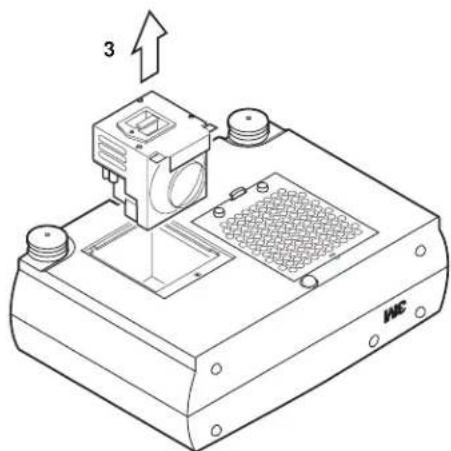
Remove lamp access door: The lamp access door is located on the bottom of the machine on the right side. Use screwdriver to unscrew the cover retaining screw (1) and gently open the cover and set it aside.
-
Retaining screws: Use a screwdriver to unscrew the lamp module retaining screws. (2)
√ Note
There are three lamp module screws that must be loosened. These screws are self-containing screws that cannot be removed from the lamp module.

Figure 6.1 Lamp Door
- Remove lamp module: Grasp the lamp module with hand and the projector body with the other hand.
Carefully slide the lamp module out (3) using steady pressure.
- Insert lamp module: Carefully insert the new lamp module. Ensure that it is fully seated.
Tighten the lamp module retaining screws to secure the lamp module in place.
Insert the hinge tabs on the left side of the lamp access door, then close and tighten the retaining screws to secure the door.
natural_image
Technical line drawing of a mechanical device with a labeled component (no text or symbols present)Figure 6.2 Lamp Module
√ Note
Reset the lamp operation hours. See section 6.2 for details.
7.1 Sympton/Solution Table
| Symptom | Cause | Solution |
| Power cannot be turned on. | ·The Main power is not turned on.·The power cord is disconnected. | ·Turn the MAIN POWER switch on.·Insert the power cord into an AC socket. |
| No picture and sound | ·The setting of the input source is not correct.·RGB/Video/Audio wiring to projector is not correct. | ·Set the correct input using the input select button of the projector or the remote control.·Connect the cable to correct input/output source. |
| Sound is heard with no picture | ·RGB/Video wiring to projector is not correct.·The brightness is set fully to dark. | ·Connect the cable to correct input/output source.·Press the MENU button and increase BRIGHTNESS. |
| Picture is displayed with no sound | ·Audio wiring to projector is not correct.·The volume is set to minimum.·The unit is muted. | ·Connect the cable to correct input/output source.·Press the VOL button and increase VOLUME.·Press the MUTE button. |
| Color is weak and tint is incorrect | ·The color and tint have been adjusted incorrectly. | ·Adjust the color and tint correctly. |
| Picture is dark | ·The brightness and contrast has been adjusted incorrectly.·The lamp needs to be replaced. | ·Adjust the brightness and contrast correctly.·Replace the lamp with a new one. |
| Picture is not clear | ·Projector is out of focus. | ·Adjust the focus. |
| LAMP indicator lights red. | ·Lamp will not ignite. | ·Turn off power and let cool for 20 minutes, then restart.·If problem persists call your dealer. |
| LAMP indicator blinks red. | ·Air filter door on bottom of case is open. | ·Ensure air filter door is closed. |
| TEMP indicator lights red. | ·Temperature inside projector is too hot. | ·Do not block the ventilation holes.·Clean air filter |
| TEMP indicator blinks red. | ·Cooling fan may be obstructed by metal screen under foam air filter. | ·Align metal screen.·If fan blade is still obstructed, call service. |
7.2 Message/Solution Table
| Error Message Displays | Cause | Solution |
| NO INPUT IS DETECTED | The projector is not detecting a signal. | Check cable connections to input device. Input device not connected to this input mode, switch to next mode. |
| SYNC IS OUT OF RANGE | The horizontal frequency of input signal exceeds projector capability. | Switch projector to correct resolution.See Appendix A.5 |
| CHANGE THE LAMP | Lamp operation time is greater than 1,900 hours. | Change the projector lamp and reset the lamp operation hours to zero. |
| RESET THE LAMP TIMER | Lamp operating time is greater than 2000 hours. Safety feature shuts projector down after 10 minutes. | Change the projector lamp and reset the lamp operation hours to zero. |
| CHECK THE AIR FLOW | Air flow to cooling fan is blocked. | Clear air flow path to fan and clean air filter. |
8.1 Service Information
For product information, product assistance, service information, or to order accessories, please call:
In U.S. or Canada: 1-800-328-1371
In other locations, contact your local 3M Sales office.
| Accessories | Part Number |
| Metal halide lamp module, 260 W | 78-6969-8782-1 |
| Power cord (US) | 26-1011-8852-7 |
| Power cord (UK) | 78-8118-3304-1 |
| Power cord (Germany) | 78-8118-3303-3 |
| VGA cable | 78-8118-3401-5 |
| MAC adapter | 78-1011-3308-2 |
| S-video cable | 26-1011-3419-0 |
| 3-conductor video/audio cable | 78-8118-3306-6 |
| Serial mouse cable | 78-8118-3426-2 |
| PS/2 mouse cable | 78-8118-3424-7 |
| ADB mouse cable | 78-8118-3425-4 |
| Stereo mini jack cable | 26-1012-0683-2 |
| Remote Control | 78-8118-3402-3 |
| Ceiling mount | 78-6969-8357-2 |
| Adjustable height suspension | 78-6969-8312-7 |
| Shipping case | 78-6969-8347-3 |
| Soft carry case | 78-6969-8346-5 |
| Soft travel case with wheels | 78-6969-8130-3 |
| Not Included with Basic Packet | Part Number |
| RS-232 control cable | 78-8118-3312-4 |
How to Order
Please order these parts through your dealer, or contact 3M Customer Service at the following number:
In U.S. or Canada: 1-800-328-1371
In other locations, contact your 3M Sales office.
The contents of this manual are subject to revision without prior notice.
3M assumes no responsibility for the infringement of special rights of a third party or other rights that may arise out of the information contained in this manual.
Reproduction of this manual in any form without prior permission is strictly prohibited.
3M will replace the manual if any pages are missing or collated incorrectly.
Table of Contents
A.1 Technical Specifications
A.2 Dimensions
A.3 Projector-to-Screen Distance
A.4 Connection to the Video Signal Terminal
A.5 Connection to the RGB Signal Terminal
A.6 Indicator Status
A.7 Connection to the Control Signal Terminal
A.1 Technical Specifications
√ Note
All specifications are subject to change without notice.
| Product name | Multimedia projector | |
| Model Name | MP8740 | |
| Display system | 3 beam poly-silicon LCD | |
| Liquid crystal panel | Panel size | 1.3 inches (33 mm) |
| Drive system | TFT active matrix | |
| Number of pixels | 786,432 pixels (V768 · H1024) per panel. 2.36 million total pixels with 3 panels. | |
| Lens | F/Number: F/2.3 - F/3.0 Focal Length: F = 48.1 - 72.1 mm (1.9" - 2.8") | |
| Lamp | Metal halide lamp 260W | |
| Speaker (stereo) | 2 watts each | |
| Power supply | AC100 ~ 120V, 5A / AC220 ~ 240V, 2.2A (Universal) | |
| Power consumption | 370W | |
| Operating temperature range | 32° ~ 95°F (0° ~ 35°C) | |
| Dimensions | 15.9" (W) · 6.1" (H) · 12.0" (D) 404 mm (W) x 154 mm (H) x 305 mm (D) | |
| Weight | 18.6 lbs. (8.4 kg) | |
| Input/Output terminal | video signal input terminal | S VIDEO : Mini DIN4-pin terminalVIDEO : RCA Jack terminalAUDIO : RCA Jack terminal |
| RGB input/output signal terminal | RGB signal : D-sub 15pin (Female)AUDIO : Stereo mini jack | |
| Control terminal | D-sub 15pin (Male) | |
A.2 Dimension

A.3 Projector-to-Screen Distance
Example of the Multimedia projector and screen installation. Determine picture size and projection distance as illustrated below.

| DistanceTo Screen Diagonal Width Height Diagonal Width Height | ||||||
| 227 cm 102 cm(7.4 ft) | 81 cm 61 cm(40 in.) | 153 cm 122 cm(32 in.) | (24 in.) | 92 cm(60 in.) | (48 in.) | (36 in.) |
| 341 cm(11.2 ft) | 152 cm(60 in.) | 121 cm(48 in.) | 91 cm(36 in.) | 228 cm(90 in.) | 183 cm(72 in.) | 137 cm(54 in.) |
| 455 cm 202 cm(15 ft) | 162 cm(80 in.) | 121 cm 304 cm(64 in.) | 243 cm(48 in.) | 182 cm(120 in.) | (96 in.) | (72 in.) |
| 569 cm 252 cm(18.7 ft) | 202 cm(99 in.) | 151 cm 379 cm(79 in.) | 303 cm(60 in.) | 227 cm(149 in.) | (119 in.) | (90 in.) |
| 682 cm 302 cm(22.4 ft) | 241 cm(119 in.) | 181 cm 454 cm(95 in.) | 363 cm(71 in.) | 272 cm(179 in.) | (143 in.) | (107 in.) |
| 853 cm 377 cm(28.0 ft) | 302 cm(148 in.) | 226 cm 556 cm(119 in.) | 453 cm(89 in.) | 340 cm(223 in.) | (178 in.) | (134 in.) |
| 1137 cm(37.3 ft) | 502 cm(198 in.) | 402 cm(158 in.) | 301 cm(119 in.) | 755 cm(297 in.) | 604 cm(238 in.) | 453 cm(178 in.) |
√ Note
These sizes are ± 1 inch. This is due to variations in the manufacture of the lens. If you are close to one of the endpoints you should verify with your unit that the image is the proper size at the proper distance.
A.4 Connection to the Video Signal Terminal
a) Input signal
| S-VIDEO signal | Luminance signal 1.0Vp-p, 75 Ω terminationChrominance signal 0.286Vp-p (burst signal), 75 Ω termination | |
| VIDEO signal | 1.0Vp-p, 75Ω termination | |
| AUDIO signal | Input | 200mVrms, 20 kΩ below (MAX 3.0Vp-p) |
| Output | 0~200mVrms, 1k Ω | |
b) Signal input terminal

√ Note
Video input signal terminals have priority in the following order:
- S-VIDEO input terminal
- RCA jack (composite) input terminal
A.5 Connection to the RGB Signal Terminal
a) Input signal / Output signal
| Video signal | Analog 0.7Vp-p 75 Ω termination (Positive polarity) | |
| Horizontal sync signal | TTL level (Positive/negative polarity) | |
| Vertical sync signal | TTL level (Positive/negative polarity) | |
| Composite sync signal | TTL level | |
| Audio signal | Input | 200mVrms, 20k Ω below (MAX 3.0Vp-p) |
| Output | 0 ~ 200mVrms, 1k Ω | |
b) Signal input terminal / output terminal
| 1 | Video signal (Red) | 9 | No Connection |
| 2 | Video signal (Green) | 10 | No Connection |
| 3 | Video signal (Blue) | 11 | Ground |
| 4 | No Connection | 12 | SDA (DDC) |
| 5 | No Connection | 13 | Horizontal/Composite sync signal |
| 6 | Ground (for R) | 14 | Vertical sync signal |
| 7 | Ground (for G) | 15 | SCL (DDC) |
| 8 | Ground (for B) |
c) Example of computer signal
| Resolution HxV | Refresh Rate Hor | zontal Standard Frequency Dots HxV | |||
| 640 x 350 70.1 | Hz 31.5 kHz VGA-1 1024 x 560 | ||||
| 640 x 400 56.4 | Hz 24.8 kHz NEC PC9801 1024 x 640 | ||||
| 640 x 400 70.1 | Hz 31.5 kHz VGA-2 1024 x 640 | ||||
| 640 x 480 85.0 | Hz 43.3 kHz VESA 863 x 640 | ||||
| 640 x 480 59.9 | Hz 31.5 kHz VESA VGA-3 1024 x 768 | ||||
| 640 x 480 66.7 | Hz 35.0 kHz | MAC 13" | 1024 x 768 | ||
| 640 x 480 72.8 | Hz 37.9 kHz VESA | 1024 x 768 | |||
| 640 x 480 75.0 | Hz 37.5 kHz VESA | 1024 x 768 | |||
| 800 x 600 56.3 | Hz 35.2 kHz VESA | 1000 x 750 | |||
| 800 x 600 60.3 | Hz 37.9 kHz VESA | 1000 x 750 | |||
| 800 x 600 72.2 | Hz 48.1 kHz VESA | 1000 x 750 | |||
| 800 x 600 75.0 | Hz 46.9 kHz VESA | 1000 x 750 | |||
| 800 x 600 85.1 | Hz 53.7 kHz VESA 800 x 600 | ||||
| 832 x 624 74.6 | Hz 49.7 kHz | MAC 16" | 980 x 735 | ||
| 1024 x 768 43.5 Hz Interlaced | 35.5 kHz VESA Compressed 853 x 640 | ||||
| 1024 x 768 | 60.0 Hz 48.4 kHz VESA | 1024 x 768 | |||
| 1024 x 768 | 70.1 Hz 56.5 kHz VESA | 1024 x 768 | |||
| 1024 x 768 | 75.0 Hz 60.0 kHz VESA | 1024 x 768 | |||
| 1152 x 864 | 75.0 Hz | 67.5 kHz | VESA | Compressed | 960 x 720 |
| 1280 x 960 | 60.0 Hz 60.0 kHz VESA | Compressed 1024 x 768 | |||
| 1280 x 1024 60.0 Hz 64.0 kHz VESA Compressed 960 x 768 | |||||
| 1280 x 1024 | 75.0 Hz | 80.0 Hz | VESA | Compressed | 960 x 768 |
Note 1: MAC adapter is necessary to set the resolution mode. Projector is compatible with 13 inch mode and 16 inch mode.
Set all dip switches OFF except those indicated in the chart. For example:
MAC 13" mode = switch 1, 5 and 6 are ON MAC 16" mode = switch 2, 5 and 6 are ON

natural_image
Diagram of an electronic component with labeled pins (no text or symbols beyond pin numbers)(Example of 16 inch mode)
Note 2: Some input sources may not be displayed properly because they are not compatible with the projector.
A.6 Indicator Status
The ON, LAMP and TEMP indicators will light or blink in the following cases:
| Indicator status | Meaning | Remedy | |
| ON indicator | Lights orange | Standby mode | normal |
| Blinks green | During warming up | normal | |
| Lights green | During operation | normal | |
| Blinks orange | During cooling down | normal | |
| LAMP indicator | Lights red | Lamp cannot light | Cool projector by power off for 20 minutes. |
| Blinks red | Air filter open | Ensure filter is closed. | |
| TEMP indicator | Lights red | Temperature inside too high | Let projector cool 20 minutes. Check air flow and filter. |
| Blinks red | Cooling fan not operating | call your dealer |
*When the LAMP indicator lights or blinks, turn the power off. If the problem persists, contact your dealer.
A.7 Connection to the Control Signal Terminal
a) Mouse emulation
(1) While the projector and computer are turned OFF, connect the projector and the mouse terminal of computer using an appropriate cable. (PS/2, Serial or ADB)
(2) Turn ON the projector.
(3) Turn ON the computer.
(4) Select the correct mouse driver for the application. See computer's User Manual for this procedure.
√ Note
In some Notebook computers which have internal pointing device, mouse emulation will not work unless the internal pointing device is disabled. In this case, disable the internal pointing device in BIOS setting. Check the computer's manual for procedure to follow to disable internal pointing device in BIOS setting.

Caution
Turn off the power to both the projector and computer before connecting. Connect the computer to the control terminal of the projector using the appropriate cable.
PS/2 mouse


flowchart
graph TD
    A["Projector"] --> B["1 CLK"]
    A --> C["2 DATA"]
    A --> D["3"]
    A --> E["4"]
    A --> F["5"]
    A --> G["6"]
    A --> H["7"]
    A --> I["8"]
    A --> J["9"]
    A --> K["10"]
    A --> L["11"]
    A --> M["12"]
    A --> N["13"]
    A --> O["14"]
    A --> P["15"]
    Q["DATA"] --> R["1 2"]
    Q --> S["2 GND"]
    Q --> T["3 +5V"]
    Q --> U["4 CLK"]
    Q --> V["5 6"]

ADB mouse

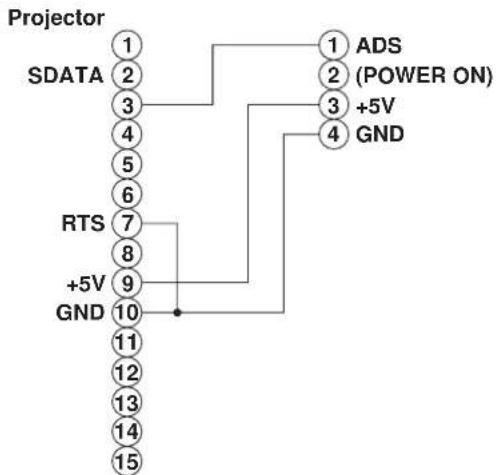
flowchart
graph TD
    A["Projector"] --> B["1"]
    A --> C["2"]
    A --> D["3"]
    A --> E["4"]
    A --> F["5"]
    A --> G["6"]
    A --> H["7"]
    A --> I["8"]
    A --> J["9"]
    A --> K["10"]
    A --> L["11"]
    A --> M["12"]
    A --> N["13"]
    A --> O["14"]
    A --> P["15"]
    Q["ADS"] --> R["2 (POWER ON)"]
    S["GND"] --> T["3 +5V"]
    S --> U["4 GND"]
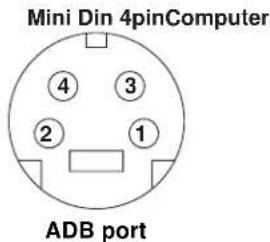
A.7 Connection to the Control Signal Terminal (continued)
Serial mouse
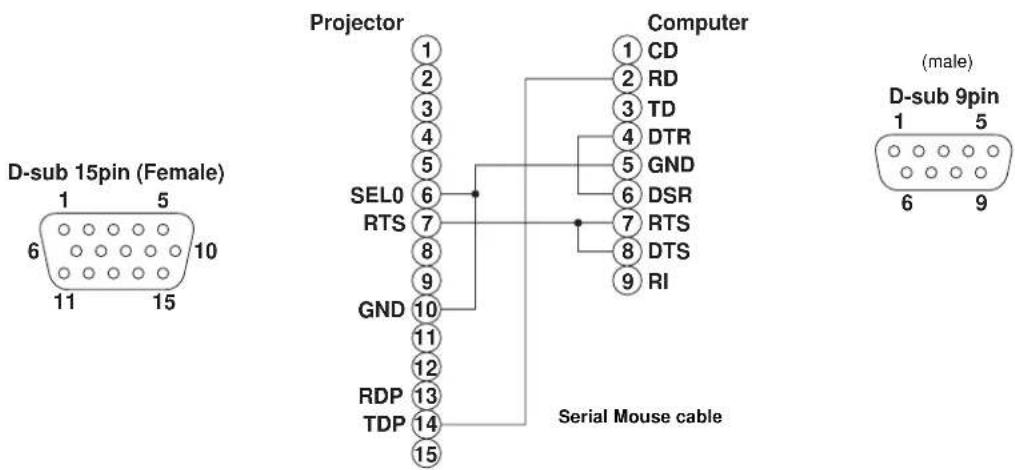
b) RS-232 Control Cable (not included with basic packout)
This cable is used to directly control the projector without using the Remote Control or Operator's Panel.

Serial Command Codes
All numbers in this document are in Hexadecimal. You must send at the same communication setting as the projector and use a null modem serial cable to connect to the projector.
There are four types of messages for the MP8740, 1) ASK, 2) REPLY, 3) SET and 4) DEFAULT.
Ask Code:
User:
20 XX
XX is the attribute you are checking.
Projector:
1Y XX Y bytes of data
This is a reply code. The Y is the number of extra bytes that come after the command.
The XX is the same as in the Ask code.
Set Code:
User:
XX is the attribute you are checking. The Y is the number of bytes for the data.
Projector:
1Y XX Y bytes of data
This is a reply code. The Y is the number of extra bytes that come after the command.
The XX is the same as in the Set code.
Default Code:
User:
40 XX
XX is the attribute you are checking.
Projector:
1Y XX Y bytes of data
This is a reply code. The Y is the number of extra bytes that come after the command.
The XX is the same as in the Ask code.
Errors:
For an error, the projector will reply with the same code that was sent but with a 0 in the first nibble.
Serial Command Code Table
| Function Command Code # Bytes Data Code Meaning | ||||
| Mouse 05 1 00 Stop mouse function | 01-7F Enable mouse function | |||
| Communication 06 | 1 0X 8N1 | 1X 7N1X0 1200 bpsX1 2400 bpsX2 4800 bpsX3 9600 bpsX4 19200 bps | ||
| Power 11 | 1 1E Power off | 1F | Power on | |
| Zoom | 12 1 01-3F Zoom + | 41-7F Zoom - | ||
| Focus | 13 1 01-3F Focus + | 41-7F Focus - | ||
| Mirror | 14 1 00 Normal | 01 H Invert02 V Invert03 H & V Invert | ||
| Input | 21 1 11 | Video 1 | 12 Video 221 RGB 122 RGB 2 | |
| Video Type | 22 2 00 00 | Auto | 00 0100 0200 03 | NTSCPALSECAM |
| Volume | 23 1 00-7F 00 - Softest | |||
| Mute | 24 1 00 Mute off | 01 Mute on | ||
| Brightness | 31 3 00 00 00 - | 7F is high | end of scale00 00 7F | |
| Contrast | 32 3 00 00 00 - | 7F is high | end of scale00 00 7F | |
| Color | 33 3 00 00 00 - | 7F is high | end of scale00 00 7F | |
| Tint | 34 | 3 | 00 00 00 -00 00 7F | 7F is green end of scale |
| Sharpness | 35 3 00 00 00 - | 7F is sharp | end of scale00 00 7F | |
| H. Phase | 37 3 00 00 00 - | 00 00 1F | ||
| H. Position | 38 4 00 00 00 00 - | 7F is right | end of scale00 00 7F 01 | |
| H. Size | 36 4 00 00 02 06 - | 1E 08 is wide | end of scale00 00 1E 08 | |
| V. Position | 3A | 3 | 00 00 00 00 -00 00 7F 01 | 7F 01 is down |
Serial Command Code Table (con't)
| Function Command Code # Bytes Data Code Meaning | ||||
| Blank 41 1 0X Blank off | 1X Blank on bit 0 - 0 Blue off bit 0 - 1 Blue on bit 1 - 0 Green off bit 1 - 1 Green on bit 2 - 0 Red off bit 2 - 1 Red on bit 3 - 0 No change bit 3 - 1 Change | |||
| Reveal 42 1 0X Stop | X1 Reveal down X4 Reveal right | X in down and right is 0 - 7 with 7 being the fastest | ||
All statements, technical information, and recommendations related to Seller's products are based on information believed to be reliable, but the accuracy or completeness thereof is not guaranteed. Before utilizing the product, the user should determine the suitability of the product for its intended use. The user assumes all risks and liability whatsoever in connection with such use.
Any statements or recommendations of the Seller which are not contained in the Seller's current publications shall have no force or effect unless contained in an agreement signed by an authorized officer of Seller. The statements contained herein are made in lieu of all warranties, expressed or implied, including but not limited to the implied warranties of merchantability and fitness for a particular purpose which warranties are hereby expressly disclaimed.
SELLER SHALL NOT BE LIABLE TO THE USER OR ANY OTHER PERSON UNDER ANY LEGAL THEORY, INCLUDING BUT NOT LIMITED TO NEGLIGENCE OR STRICT LIABILITY, FOR ANY INJURY OR FOR AN DIRECT, INDIRECT, INCIDENTAL OR CONSEQUENTIAL DAMAGES SUSTAINED OR INCURRED BY REASON OF THE USE OF ANY OF THE SELLER'S PRODUCTS.
Let us help you make the most of your next presentation. We offer everything from presentation supplies to tips for better meetings. And we're the only transparency manufacturer that offers a recycling program for your used transparencies. For late-breaking news, handy reference and free product samples, call us toll-free in the continental United States and Canada from 7:30 a.m. to 5:30 p.m. (CST) or visit our Internet Website.

http://www.mmm.com/presentations e-mail: presentations@mmm.com
3M Austin Center
Building A145-5N-01 6801 River Place Blvd. Austin, TX 78726-9000
3M Canada
P.O. Box 5757 London, Ontario N6A 4T1
3M Mexico, S.A. de C.V.
Apartado Postal 14-139 Mexico, D.F. 07000 Mexico
3M Europe
Boulevard de l'Oise 95006 Cerge Pontoise Cedex France

Printed on 50% recycled wastepaper, including 10% post-consumer
Litho in USA © 3M 1999 78-6970-8972-6 Rev. A
- Safeguards 1
- Warranty 2
- Section 1: Unpack ....3
- Section 2: Product Description ....4
- Section 3: Basic Operations....7
- Section 4: Adjustments and Functions......8
- Section 5: Maintenance....14
- Section 6: Lamp....15
- Section 7: Troubleshooting ....17
- Section 8: Accessories .... 18
- Appendix: Technical Information......A.1
- INTENDED USE
- IMPORTANT SAFEGUARDS
- SAVE THESE INSTRUCTIONS
- THANK YOU FOR CHOOSING 3M
- LIMITED WARRANTY
- LIMITATION OF LIABILITY
- Contents of Shipping Box
- Optional Accessories
- Keep Your Packaging Materials
- √ Important
- What Next?
- Machine Characteristics
- √ Note
- Part Identification List
- System Set Up - connecting various equipment
- Apple™ Desktop Mouse - The Macintosh operating system should recognize the MP8740 as a mouse without any drivers being loaded.
- Remote Control Transmitter Identification
- Projector Startup
- Projector Shutdown
- Caution
- Menu Navigation
- Factory Default Setting:
- How To Use Height Adjustment Feet
- SETUP
- INPUT
- IMAGE
- OPT
- Cleaning the Air Filter
- Lamp
- Display Lamp Operation Hours
- Replacing the Lamp
- WARNING
- Service Information
- How to Order
- Table of Contents
- A.1 Technical Specifications
- A.2 Dimension
- A.3 Projector-to-Screen Distance
- A.4 Connection to the Video Signal Terminal
- a) Input signal
- b) Signal input terminal
- A.5 Connection to the RGB Signal Terminal
- a) Input signal / Output signal
- b) Signal input terminal / output terminal
- c) Example of computer signal
- A.6 Indicator Status
- A.7 Connection to the Control Signal Terminal
- a) Mouse emulation
- PS/2 mouse
- ADB mouse
- A.7 Connection to the Control Signal Terminal (continued)
- b) RS-232 Control Cable (not included with basic packout)
- Serial Command Codes
- Default Code:
Brand : 3M
Model : MP8740
Category : Video projector