
14889 - Loudspeaker MONOPRICE - Free user manual and instructions
Find the device manual for free 14889 MONOPRICE in PDF.


| Product Type | Outdoor Horn Speaker |
| Brand | Monoprice |
| Model | 14889 |
| Maximum Input Power | 50 watts |
| Frequency Response | 90 Hz – 20 kHz |
| Sound Pressure Level (SPL) | 116 dB ±3 dB |
| Impedance (per tap) | Red: 800 ohms, Green: 400 ohms, White: 200 ohms |
| 70V Power Taps | Red: 6.25 W, Green: 12.5 W, White: 25 W |
| 100V Power Taps | Red: 12.5 W, Green: 25 W, White: 50 W |
| Ingress Protection Rating | IPX6 (weatherproof) |
| Dimensions (W x H x D) | 14.2" x 10.0" x 12.4" (360 x 255 x 315 mm) |
| Weight | 8.8 lbs (4.0 kg) |
| Mounting | Included bracket, 3 screws (not included) |
| Speaker Type | Constant voltage (70V/100V) system |
| Wiring Configuration | Parallel connection for multiple speakers |
| Volume Control | Adjustable via wattage tap selection |
| Safety Features | Turn off power before connections; use correct polarity; avoid clipping |
| Cleaning | Soft dry cloth; mild soap for stubborn dirt |
| Regulatory Compliance | FCC Part 15 Class B, ICES-003 |
Frequently Asked Questions - 14889 MONOPRICE
User questions about 14889 MONOPRICE
0 question about this device. Answer the ones you know or ask your own.
Ask a new question about this device
Download the instructions for your Loudspeaker in PDF format for free! Find your manual 14889 - MONOPRICE and take your electronic device back in hand. On this page are published all the documents necessary for the use of your device. 14889 by MONOPRICE.
USER MANUAL 14889 MONOPRICE
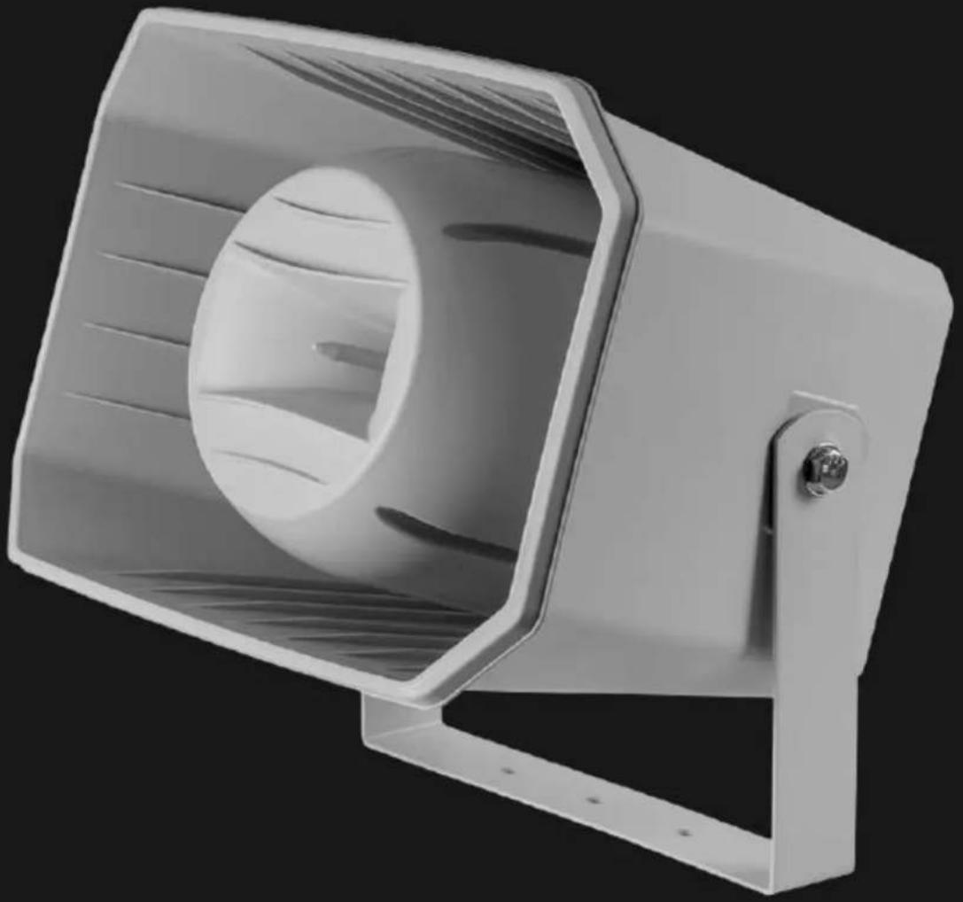
50 Watt 5 x 3 inch Outdoor Horn Speaker
User's Manual
natural_image
White rectangular spray gun with a circular vent, mounted on a metal frame (no text or symbols visible)SAFETY WARNINGS AND GUIDELINES
- Turn off and unplug all equipment prior to making electrical connections, including speaker wire connections.
- Reduce the volume level prior to making any change to the audio input source, e.g., changing radio stations or changing CDs.
- Ensure that the speaker terminal cover is properly secured to maintain the IPX6 waterproof rating.
- When using this speaker as part of a constant voltage speaker system, ensure that the amplifier power is at least 20% higher than the total power settings of the connected speakers.
- Most speaker damage is caused by clipping, which is heard as distortion. If you hear distortion, reduce the volume level until the audio is no longer distorted.
- Take care to ensure that the speaker wire connections are properly polarized. Inverted polarization can result in unnatural or attenuated sound, especially in the bass frequencies.
- Do not use chemical cleaners or solvents to clean this speaker. Use only a soft, dry cloth. Moisten the cloth with warm water for particularly stubborn deposits.
INTRODUCTION
Thank you for purchasing this Outdoor Horn Speaker!
This high fidelity horn speaker features a 90Hz to 20kHz frequency response and 99dB SPL. It carries an IPX6 ingress protection rating, making it safe for use in all weather conditions. Featuring a built-in step-down transformer with three taps, it can be installed as part of a 70V or 100V constant voltage speaker array.
FEATURES
- All weather outdoor speaker with an IPX6 ingress protection rating
- 90Hz \~ 20kHz frequency response
• 116dB sound pressure level - Built-in step-down transformer for use in a 70V or 100V constant voltage speaker array
• Handles up to 50-watts of power - Includes mounting bracket
PACKAGE CONTENTS
Please take an inventory of the package contents to ensure you have all the items listed below.
1x Outdoor horn speaker with mounting bracket
1x User's manual
CONSTANT VOLTAGE VS 8-OHM SPEAKER SYSTEMS
A constant voltage speaker system differs from a traditional 8-ohm speaker system in that it uses a step-up transformer at the audio source to raise the voltage and lower the current on the transmission line. At the speaker end, a step-down transformer converts the signal back to a normal speaker level voltage. This reduces power loss during transmission, which allows for the use of longer speaker wire runs using smaller gauge wire.
Additionally, a constant voltage speaker system allows for the use of multiple speakers on each channel, without the need for complicated impedance calculations and configurations. In a constant voltage system, all speakers on a given channel are connected in parallel and the complicated impedance calculations are replaced by simple wattage calculations.
For example, if you want to connect two speakers per channel in a traditional 8-ohm speaker system, you must either connect them in series, which results in an overall 16-ohm impedance, or in parallel, which results in an overall 4-ohm impedance. In the first case, the 16-ohms impedance effectively halves the output power of your amplifier, resulting in lower overall volume levels. In the latter case, the 4-ohms impedance means that your amplifier will have to work harder and must be rated as stable at 4 ohms. Adding a third speaker to the mix would complicate it further, producing either a 24-ohm or 2.67-ohm overall impedance. Note that very few amplifiers are stable under 2-ohm loads, so that is usually not an option.
On the other hand, with a constant voltage system, you consider first the RMS output wattage of the amplifier. This should be reduced by 20% to compensate for insertion loss. For example, if using a 100-watt amplifier, the total load from speakers should not exceed 80 watts.
Each individual speaker on a given channel is set to a value such that the total does not exceed the rated power, less 20%. You do not need to worry about making the total as close as possible to the limit; just ensure that the total does not exceed the limit.
If all speakers are set to the same wattage value, they will all have the same volume level. If one speaker is set to a higher wattage value, it will be louder than the others, while a speaker set to a smaller value will be quieter than the others. This allows you to compensate for the environment in which the speaker is placed. For example, a speaker placed outside would need to be louder than a speaker
placed in a small room.
SPEAKER WIRING
Most constant voltage speaker installations will consist of multiple speakers per channel, with all speakers connected in parallel, as shown in the diagram to the right.
To wire speakers in parallel, connect the first speaker to the amplifier as normal. Connect the positive terminal on the first speaker to the positive terminal of the second speaker, and
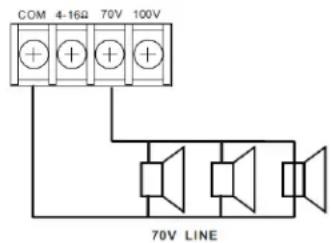
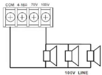
the negative terminal on the first speaker to the negative terminal on the second. Repeat for each additional speaker in the array.
INSTALLATION
Perform the following steps to install and setup this speaker for operation.
- Power off and unplug all equipment that will be connected to this speaker.
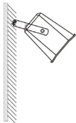
- Determine the mounting location for the speaker. Drill three pilot holes, 60mm apart using a 9.5mm drill bit. Use the speaker bracket to mark the holes before drilling.
- Using three screws (not included), secure the speaker bracket to the mounting surface.
- Multiply the rated RMS power output of your amplifier by 0.8 to determine the maximum total wattage for the speaker array.
Example: If you are using the 14886 120-watt PA amplifier, the maximum wattage of the connected speaker array is 120 × 0.8 = 96 watts.
- Assuming you want all speakers in the array to produce the same volume level, divide the calculated maximum wattage by the number of speakers in the array to determine the maximum wattage value for each speaker in the array.
Example, if you are connecting six of these 14889 outdoor horn speakers to the 14886 120-watt PA amplifier, the maximum wattage value for each speaker in the system is 96 / 6 = 16 watts. - Using a Phillips screwdriver, remove the terminal cover from the rear of the speaker.
- Loosen the nut on the waterproof wire gland to expand the opening. Feed the speaker wire through the opening.
- The speaker has three wattage taps which are selected by connecting to the wire terminal with the red, green, or white leads. These leads represent the following wattage values in 70V and 100V systems.
natural_image
Simple line drawing of a mechanical lever attached to a vertical surface (no text or symbols)| Transformer Taps | Red | Green | White |
| 70V Array | 6.25 watts | 12.5 watts | 25 watts |
| 100V Array | 12.5 watts | 25 watts | 50 watts |
Connect the positive speaker wire lead to one of the terminals opposite the red, green, or white lead.
- Connect the negative speaker wire lead to the terminal with the black common lead.
- If installing additional speakers in the array, feed another speaker wire through the waterproof wire gland, then connect the leads to the same taps as the other speaker wire, taking care to maintain proper polarity.
- Replace the waterproof cover over the speaker terminals, then tighten the nut on the waterproof wire gland to create a watertight seal around the speaker wire(s).
- Connect the speaker wire from the first speaker in the chain to the 70V or 100V output terminals on your constant voltage amplifier, taking care to maintain proper polarity.
Congratulations, your speaker array is installed and ready for use!
TROUBLESHOOTING
Q1: The sound from one of the speakers is muddy, with attenuated bass response.
A1: Double check the polarity connections.
Q2: The sound from one of the speakers is louder or quieter than the other speakers in a constant voltage system.
A2: Check the wattage selection for the affected speaker. If it is higher than that of the other speakers, it will be louder. Similarly, if a lower value is used, it will be quieter than the other speakers. To get the same volume level, use the same wattage taps on all speakers in the array.
Q3: The sound from all the speakers is scratchy, harsh, or fuzzy sounding.
A3: You are hearing audible distortion, which can cause damage to both the speakers and the amplifier. Reduce the volume level until distortion can no longer be heard in any part of the audio signal.
SPECIFICATIONS
| Model | 14889 |
| Maximum Input Power | 50 watts |
| Frequency Response | 90Hz ~ 20kHz |
| SPL | 116dB ±3dB |
| 70V Power Taps | Red: 6.25 watts, Green: 12.5 watts, White: 25 watts |
| 100V Power Taps | Red: 12.5 watts, Green: 25 watts, White: 50 watts |
| Impedance | Red: 800 ohms, Green: 400 ohms, White: 200 ohms |
| IP Rating | IPX6 |
| Dimensions | 14.2" x 10.0" x 12.4" (360 x 255 x 315 mm) |
| Weight | 8.8 lbs. (4.0kg) |
REGULATORY COMPLIANCE
Notice for FCC

This device complies with Part 15 of the FCC rules. Operation is subject to the following two conditions: (1) this device may not cause harmful interference, and (2) this device must accept any interference received, including interference that may cause undesired operation.
Modifying the equipment without authorization may result in the equipment no longer complying with FCC requirements for Class B digital devices. In that event, your right to use the equipment may be limited by FCC regulations, and you may be required to correct any interference to radio or television communications at your own expense.
This equipment has been tested and found to comply with the limits for a Class B digital device, pursuant to Part 15 of the FCC Rules. These limits are designed to provide reasonable protection against harmful interference in a residential installation. This equipment generates, uses and can radiate radio frequency energy and, if not installed and used in accordance with the instructions, may cause harmful interference to radio communications. However, there is no guarantee that interference will not occur in a particular installation. If this equipment does cause harmful interference to radio or television reception, which can be determined by turning the equipment off and on, the user is encouraged to try to correct the interference by one or more of the following measures:
- Reorient or relocate the receiving antenna.
- Increase the separation between the equipment and receiver.
- Connect the equipment into an outlet on a circuit different from that to which the receiver is connected.
- Consult the dealer or an experienced radio/TV technician for help.
Notice for Industry Canada
This Class B digital apparatus complies with Canadian ICES-003.
Brand : MONOPRICE
Model : 14889
Category : Loudspeaker