ILSTRGBA033E - Lighting Integral LED - Free user manual and instructions
Find the device manual for free ILSTRGBA033E Integral LED in PDF.

User questions about ILSTRGBA033E Integral LED
0 question about this device. Answer the ones you know or ask your own.
Ask a new question about this device
Download the instructions for your Lighting in PDF format for free! Find your manual ILSTRGBA033E - Integral LED and take your electronic device back in hand. On this page are published all the documents necessary for the use of your device. ILSTRGBA033E by Integral LED.
USER MANUAL ILSTRGBA033E Integral LED
Flexible 24V INTEGRAL LED RGB Strip IP33
Installation Guide

WARNING

DO NOT CONNECT THE LED STRIP DIRECTLY TO A MAINS SUPPLY.
THE LED STRIP MUST ONLY BE CONNECTED TO A SUITABLE 24V LED DRIVER.
IMPORTANT NOTICE
- This product should be installed according to the instructions in this guide and by a qualified electrical installer.
- All electrical work must be completed in accordance with the latest IET wiring regulations (formally IEE) for the UK or in accordance with all applicable regulations and laws in the country in which it is being installed. This product falls under a low voltage Class III circuit category.
- Switch OFF power at the mains before installing the LED strip
- Strip must only be installed indoors, in a dry area
- Avoid looking directly at the strip when turned on, for a long period of time
- Observe the operating temperature of the LED strip: -25C to +60C

To avoid any damage to the LED strip or driver;
• Always disconnect or switch off the power supply before cutting or connecting an LED strip. Wait at least one minute before connecting to a recently powered driver.
• Always handle the LED strip with care.
- Observe the correct polarity for 24V connections (fig 1).
- Safely route and secure all wires so they cannot be pinched or damaged
- Do NOT power the strip whilst in its packaging reel
- Do NOT twist the LED strip or touch the LEDs on the strip surface
• To avoid damage or malfunction, Do NOT coat the LED strip with paint, varnish or similar.
In the bag
1 X 5M ±5cm IP33 INTEGRAL LED RGB STRIP on reel pre-fitted with an appropriate connector to connect to a suitable control unit and power supply.
Accessories For IP33
1 X Clip-on strip connector
If you cut the strip into two pieces, you can use this connector to power the remaining portion of the strip.

natural_image
Close-up of a black electrical connector with wires and connectors (no visible text or symbols)INTRODUCTION
- This installation guide is for flexible, IP33 constant voltage self-adhesive LED strips produced by Integral LED.
• Depending on your installation, you can purchase optional or additional accessories such as mounting clips and connectors.
A) CHOOSING A 24V LED DRIVER
- This LED strip operates with a 24V DC constant-voltage power supply known as a driver. Drivers are sold separately and are available in varying wattage outputs.
- The specification of the driver required will depend on the total power requirement of the connected strip(s). The power output of the driver (wattage rating) must be at least 20% higher than the total required wattage of the strip(s) being powered.
For example, if you are installing 5 LED strips of 1M each and the power requirement of each 1M strip is 3W/metre – the total power requirement is 15W.
The power rating of the driver should be a least 20% above 15W i.e. A minimum of 18W.
B) PRE-INSTALLATION GUIDE
LED strips make a great addition to any domestic or commercial environment. They can change the mood and look of a space instantly and are very energy efficient. The possibilities are endless so the requirement for each lighting project will be different.
It is worth taking some time to plan your project for the desired effect before removing the backing tape on the LED strip. The specification, length, mounting position and distance from an object determines the appearance of a lit LED strip. You will also need to consider the placement and concealment, of the 24V LED driver, control unit and wires, and the power switch to turn the LED strip ON and OFF.
We recommend that you test the strip by temporarily holding the LED strip in place by using a suitable tape, such as masking tape. Safely connect the power supply - you can then carefully move the strip to try different angles and positions to gain the desired illumination effect and position. Check for light spots, reflections and shadows.
Please consider the surface you are applying the LED strip to; the surface should be stable, clean and smooth. On removal of a fixed LED strip - damage to paint, wallpaper or other substrates may occur. Take care in measuring the length required before cutting the strip, take into account the space required for the connector. You may also consider using a spirit level, plumb line or other guide if required.
C) POWER SUPPLY CONFIGURATIONS AND WIRING
1) POWERING THE STRIP
The LED strip is powered by a suitable 24V LED driver. Ensure the power is OFF and that the correct polarity is observed when wiring the LED driver. (fig 1)
| Typical installation configuration | |
| Straight runAn LED driver powers the control unit and the first LED strip. Additional strips can be connected in series. The installer will need to consider voltage drop (see 2). | fig 2 |
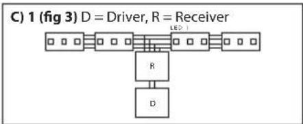
| Powered from the centrePower one or two equal lengths of LED strip from the centre.This configuration will give the best results. | fig 3 |
| Additional accessories (sold separately) may be required for complex configurations. | |
2) VOLTAGE DROP
If the total length of LED strips powered by a single LED driver is too long, you may find that the LEDs furthest away from the driver will be unlit or dimmed. To avoid this you will need to use additional drivers. For instance if you are powering 2 X 5M strips from one driver – you will need to split the run into separate 5M runs each powered by its own driver.
D) PRECAUTIONS FOR INSTALLING THE INTEGRAL LED STRIP
- Please check the bag contents before installation.
- Do not remove the strip from the packaging until ready for installation.
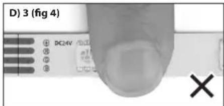
- Do NOT touch or press the LEDs or other components during installation (fig 4).
- Do not power the strip before completely releasing it from the reel.
- Do not twist the LED strip (fig 5).
- Do not install the product in an environment, which exposes it to direct sunlight, rain, water, moisture or other particles.
- If the product needs to be cut to length; please measure carefully and cut squarely at the appropriate cut marks only using a sharp pair of scissors (fig 6).
- To fix the LED strip to a smooth surface; the strip is pre-fitted with 3M adhesive backing tape. Ensure that the mounting surface is clean, dry and free from any oils, grease or wax.
- The Integral LED strip has excellent flexibility but requires the bending diameter to be no smaller than 50 mm (fig 7).
- The strip is pre-fitted with V+/R/G/B connection wires at one end. Check the supply voltage and wire connections to control unit and LED driver before switching the power on.
⚠️AUTION – Twisting, pressing on LEDs, over-bending the strip, cutting at non-cut points, incorrectly powering the strip or exposing a standard strip (IP33) to water, particles or direct sunlight will invalidate the warranty (your statutory rights remain unaffected).
E) INSTALLATION INSTRUCTIONS
- To ensure a successful installation - please read the precautions and pre-installation recommendations above.
- The mounting surface must be clean, dry and free from dust or grease.
- Release the LED strip from the package and unreel.
- Measure and cut the LED strip to the required length (only cut at the cut marks with power OFF).
- Remove the 3M self-adhesive backing tape from the strip gradually during installation. Do not remove it all at once to avoid the strip becoming entangled and sticking to itself (figs 8 and 9).
- Stick the LED strip to the mounting surface by pressing on the strip in between components only. Do NOT press on the LEDs or other components on the strip.
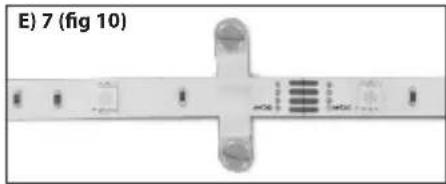
- You can use optional mounting clips (purchased separately) to secure the strip at intervals (fig 10). The mounting clips are supplied without screws and it is the responsibility of the installer to select the correct type of screw depending on mounting substrate.
- Once the strip is affixed, it is then ready to be wired. Please see section C1.
F) JOINING TWO STRIPS TOGETHER WITH ADDITIONAL ACCESSORIES
1) Integral LED is keen to make the installation easier and less labour intensive. If you are joining two IP33 strips together, our press-on connectors should be used which are available for purchase.
| a. To connect strips inline ILSRGBCONN-BLOCK5PC | |
| b. To connect Strips not inline or spaced ILSRGBCONN-2WAY5PC | |
| c. To connect power to a cut strip ILSRGBCONN-POWER5PC | |

text_image
C) 1 (fig 1) D = Driver, R = Receiver 200-240V AC DC+ 24V DC DC+ R V+ R R N
flowchart
graph TD
    A["D Driver"] --> B["R Receiver"]
    B --> C["LED¹"]
    D["D Driver"] --> E["R Receiver"]
    E --> F["LED¹"]
    G["D Driver"] --> H["R Receiver"]
    H --> I["LED¹"]
    J["MAX RUN = 5 Metres"]
flowchart
graph TD
    A["Driver"] --> B["T形结构"]
    B --> C["R"]
    B --> D["D"]
    style A fill:#f9f,stroke:#333
    style B fill:#ccf,stroke:#333
    style C fill:#cfc,stroke:#333
    style D fill:#fcc,stroke:#333
text_image
D) 3 (fig 4)
text_image
D) 5 (fig 5)
text_image
D) 7 (fig 6)
text_image
D) 9 (fig 7) >=50mm
text_image
E) 5 (fig 8)
natural_image
Close-up of a twisted rope or tape with a cross mark, no visible text or symbolsCAUTION: When applying connectors to the strip, ensure that the correct polarity is observed.
Always observe polarity for 24V connections to control unit, positive (+) to positive, red (R) to red, green(G) to green and blue (B) to blue.
Check the wire connections before switching the power on. Ensure that the strip is cut correctly and that the strip terminals make good contact with the connector terminals. Ensure the back tape of strip is removed completely when connectors are applied.
G) TROUBLESHOOTING
⚠️ Always switch OFF power before adjusting the wiring or strip.
| Symptoms Possible Causes Solutions | ||
| None of the LEDs light up | 1. No power to the driver. Please check to see if there is power being delivered to the drivers power supply via the connection to AC power. | |
| 2. The power supply driver connection is wired incorrectly. | Check the polarity for 24V connections, positive (+) to positive and negative (−) to negative. See power supply driver wiring diagram (Section C1). | |
| 3. There is no output voltage from the power supply driver. | Check the power supply driver; it may need to be replaced. | |
| 4. The strip wires are not connected properly to the strip or to the control unit, or the control unit to the driver. | Check the connectors and polarity. Make sure strip is cut correctly and strip terminals are making a connection within the connector. | |
| 5. Overvoltage may have damaged the LEDs. | The working voltage should be within 5% of the rated voltage (24V). If overvoltage has damaged the product then this is not covered by the warranty. | |
| Some of the LEDs do not work | 1. LEDs on the strip are powered in series. If some LEDs in the centre of the strip do not light and LEDs towards the end of the strip do light then the LEDs have failed. | Strip may need to be replaced. |
| 2. If the LEDs in the beginning of the strip work but none are working after the first non-working LED then there is a connection issue. This could be caused by a poor connection or if the connector is not fitted to the strip correctly. This could also be a result of the strip being bent more than the recommended bending diameter. | Please check the strip connection from the section of the strip that is not lit. Check soldering connections. Check connector joins. Strip may need to be replaced. | |
| The strip when lit is dim or not evenly lit | 1. The power load (total Wattage of all strips connected) exceeds the rated Wattage of the power supply driver (total output). | The power supply needed will depend on the total length of strips in use. The power supply driver will need to have an output that is at least 20% more than the total wattage needed to power the strip. See section A. |
| 2. The length of wire between the strip and power supply or the length of the wire in between each strip is too long. | 1. Use shorter strip supply wires.2. Use thicker supply wires.3. Make sure that the input voltage of each LED strip is within 90% of the rated voltage. | |
| 3. Too many LED strips are connected to the power supply driver. | 2. Make sure that the total wattage of all LED strips is within 80% of the total output of the power supply driver. If the total wattage of all strips exceeds the driver output then please use a higher wattage driver. | |
| All LEDs are flashing intermittently | There is an intermittent connection at the power supply driver. | Please check driver to AC connection and driver to control unit and control unit to strip connection. |
| Some of the LEDs are flashing intermittently | There is an intermittent connection at each strip branch connection. | Please check all strip connections and check connector joins. |
| LEDs blink once when power is switch on | Please check that the driver is compatible. | This is a 24V constant voltage LED strip. You will need to power the strip using a 24V constant voltage LED driver. |
natural_image
Diagram of a mechanical or electronic component with labeled parts and cross-shaped features (no readable text or symbols)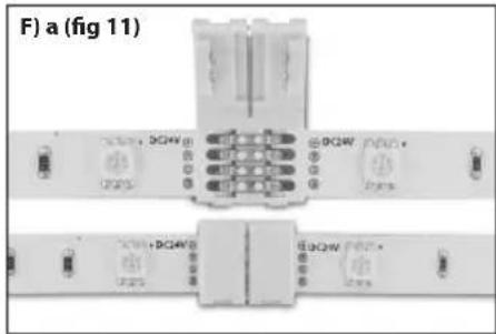
text_image
F) a (fig 11)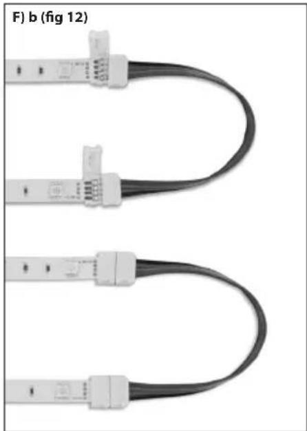
natural_image
Three U-shaped cable connectors with connector logos, shown from top to bottom (no text or symbols on the cables themselves)
natural_image
Two black cable connectors with white connectors and wiring, shown in side view (no text or symbols)Limited 3-year warranty
This product is for indoor use in dry locations. Improper installation, abuse or miss-powering of the strip or failure to use the LED strip for its intended purpose will void the warranty. LED strips cannot be returned or exchanged once cut (unless the strip is faulty due to parts or workmanship). Proof of purchase is required for all returns. Your statutory rights remain unaffected. Please see www.integral-led/warranty
Questions? Please contact your supplier or see integral-led.com

All Trademarks Acknowledged
Integral LED is a division of Integral Memory plc
London NW10 0UF
integral™
LED
www.integral-led.com