TC 5016-IP-PTZ - Security Camera TECNO - Free user manual and instructions
Find the device manual for free TC 5016-IP-PTZ TECNO in PDF.


| Product Type | Mini PTZ Bullet Camera |
| Image Sensor | 1/2.7" Progressive Scan CMOS |
| Resolution | 1920 x 1080 (Full HD) |
| Video Compression | H.264 Main Profile, M-JPEG |
| Streaming | Dual-stream (Main & Sub) |
| PTZ Range | Pan: 260°, Tilt: -5° to 60° |
| PTZ Speed | Manual: 0.01°~12°/s, Preset: 12°/s |
| Presets | 256 |
| Patrol Paths | 8 paths, up to 32 presets per path |
| Patterns | 4 patterns, 500 orders or 600 seconds each |
| Auto Scan | 8 paths with adjustable speed and limits |
| Lens | Auto-focus, 3x/10x optical zoom (model dependent) |
| Day/Night | Auto IR cut filter, color/B&W switch |
| WDR | Wide Dynamic Range (On/Off) |
| White Balance | Auto/Manual |
| Back Light Compensation | Auto BLC |
| IR LED | Smart IR with near/far power adjustment (1-10) |
| Audio | Two-way audio (Line In/Mic In, Line Out) |
| Alarm | 1 input, 1 output, alarm linkage |
| Network Protocols | TCP/IP, PPPoE, DDNS, FTP, UPnP, ONVIF |
| Storage | TF card slot (max 128GB, not included) |
| Protection Rating | IP66, 3000V lightning protection |
| Power Supply | DC 12V, 12W |
| Operating Temperature | -35°C to 60°C (-31°F to 140°F) |
| Humidity | <95% (non-condensing) |
| Housing Material | Alufer (aluminum alloy) |
| Dimensions | Ø130 × 200 mm (approx.) |
| Weight | 1.2 kg (approx.) |
Frequently Asked Questions - TC 5016-IP-PTZ TECNO
User questions about TC 5016-IP-PTZ TECNO
0 question about this device. Answer the ones you know or ask your own.
Ask a new question about this device
Download the instructions for your Security Camera in PDF format for free! Find your manual TC 5016-IP-PTZ - TECNO and take your electronic device back in hand. On this page are published all the documents necessary for the use of your device. TC 5016-IP-PTZ by TECNO.
USER MANUAL TC 5016-IP-PTZ TECNO
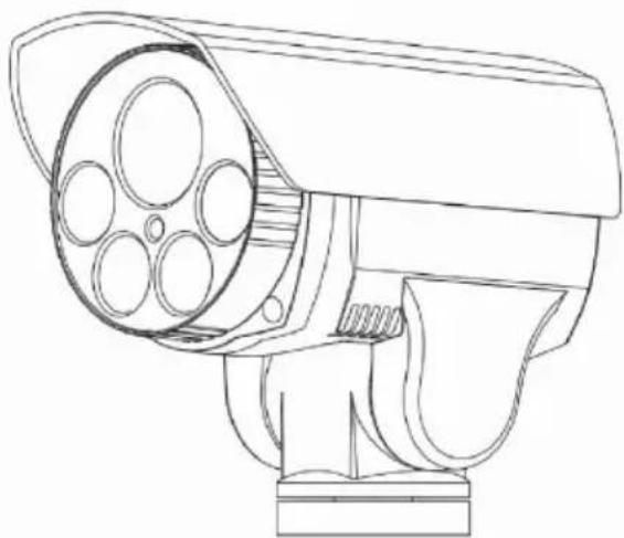
MINI PTZ BULLET CAMERA
natural_image
Line drawing of a surveillance camera with multiple lenses and a mounted base (no text or symbols)USER'S MANUAL V1.0
Announcements
- Before installing or using the infrared network camera, please read this manual carefully.
- Transportation
In the process of transportation and reserve, users should avoid great pressure, vibration and soaking which might cause damages to the product. This product must transport in parts, and it is not under warranty if transporting in whole and being damaged, whatever it is sent by suppliers or refurbished by factories.
- Installation
This product is installed on the wall and it cannot be installed with others. Please avoid damaging any components with high pressure or vibration since it would weaken the performance of the camera. The transparent cover of network is advanced optical product and please avoid touch it with hand directly. Installation must obey all rules of safety of electricity and gases with corresponding own power. While the camera is working, it must keep enough distance with high-voltage lines, and safeguard is needed if necessary. Do not be electrified if all installation is not finished.
- Do Not Dismantle
Do not dismantle the components in the camera and there is no any parts which can be fixed by users themselves. The maintenance must be done by professionals.
● Far away to electromagnetic fields
If the camera is working around the televisions, radio transmitters, electromagnetic devices, electrical machinery, transformer, or loudspeakers, the images on the camera would be affected by electromagnetic fields of those devices.
- Do not focus on highlight
Do not focus on highlight whatever the power of camera is working, otherwise the irreparable damages will be caused to CCD of the camera.
- Services
Please avoid impact or vibration and do not clean the core of camera with abrasive cleansers. If necessary, use dry soft cloth or neutral cleanser.
- Environment
| Temperature | - 35 ~ 60°C |
| Humidity | <95%(No condensation ) |
| Atmosphere | 86 ~ 106KPa |
| Power | DC12V |
Catalog
Introduction 1
2 Operation with Browser ...... 6
3 Operation on Menu 35
4 Customer Service 55
5 Appendix 57
Introduction
1.1 Specification
1.1.1 Features
- HD Quality
This infrared network camera applies H.264 Compression Code. It has high compression rate and saves bandwidth and capacity of hard disks. The rate of width and height can be adjusted to 16:9 or 4:3 and the camera can output H.264 Main Profile or M-JPEG video flow with full frame rate. It also supplies encoded parameter adjustment in dynamic.
●Fixed Focus, Zoom and Auto-focus
Infrared network camera has functions in fixed focus, 3X Zoom, 10X Zoom and auto focus. It not only supplies ideal sights, but also realizes perfect automatic focusing.
- Dual-stream Switch
It supplies dual-stream so that users could choose main stream or substream for different application.
- Agreements
It supplies agreements, such as TCP/IP, PPPoE, DDNS, FTP, UPNP, and Onvif Open Standards.
- Audio Chat
It supplies audio chat.
- Alarm
It supplies the linkage between local alarm signal and network alarm signal. Also, it could alarm users for dangers from different areas, even for somewhere covered.
•ROI
It could aggregate the streams so that the screen would describe areas more clearly, which applies to lack of streams.
- OSD
It supplies text overlay.
●Memorizes before the power down
If the camera stayed in a position for a few minutes before its power shut down, it would come back to this position after recharge-in.
1.1.2 Functions
- Enables stepless speed change and automatic match of zoom speed.
- Lowest moving speed is 0.01^ / s manually and highest speed is 12^ / s which could locate accurately.
-
256 presets for custom; auto patrol with 8 paths and 32 presets on each path.
-
8 paths for auto scan; margins and scan speed could be adjusted on each paths.
- 4 patterns; 500 orders or 600-second path could be noted on each pattern.
●2 circuits; one for alarm import and one for export. - Alarm linkage among preset, patrol, pattern, TF-card recording, trigger switch output, capture, FTP upload, mails.
1.1.3 Integrated network camera
- The latest update of the direction change of gears; enhances integration and transmission.
- The latest update of ultra-slim-precision-stepper-motor drive; works steadily and locates accurately.
- Combined together for integration.
- Excellent mechanical drive; supplies 260^ pan rotation.
- Stepless speed change and automatic match of zoom speed.
- Supplies -5°\~60° tilt rotation and auto reversal.
- Manual speed: 0.01^ 12^ / s ; patrol speed: 12^ / s .
1.1.4 HD color video camera
●Auto Iris and WDR.
●Auto/Manual White Balance.
●Auto/Manual Focus.
●Auto Brightness Control.
- HD color video camera.
1.1.5 24-hour outdoor design
●Auto control with built-in sensor.
- Works under 60°C
- The cover of camera is made of alufer so that it is solid.
●Level of protection achieves IP66 criterion.
●Built-in 3000V lightning protection and waves protection.
1.2 Functions
This part describes the main function of infrared network camera and some rules it realizes, but does not contain the method of operation. Generally, users should regard the manual from system manufacturer as the criterion. However, in some cases, there might have some specific requests and methods. Please contact with suppliers for significant information.
● Auto match for focal distance or rotation speed
According to the distance of focus, the camera would adjust its rotation speed automatically, which is more convenient than operating it manually.
- Adjust or call presets
Preset is a function which saves some parameters, such as horizontal angles, vertical angles, focal distance into camera. If needed, users could call these presets quickly, and adjust the camera to this position. Keyboards are used for saving or calling presets usually; this camera supplies 256 presets.
- Auto Scan
Users could adjust margins with keyboards previously so that the camera could scan these areas automatically in a constant speed.
- Patrol
By programming previously, network camera would order some presets into the patrol and scan them automatically. Users could also control the keyboards in order to adjust the camera in regular period.
- Pattern
The network camera could remember 600-second path or 500 orders. After turning on this function, the camera would scan the area with adjusted path automatically.
- Memorizes before the power down
If the camera stayed in a position for a few minutes before its power shut down, it would come back to this position after recharge-in.
• ROI
It could aggregate the streams so that the screen would describe areas more clearly, which applies to lack of streams.
- Lens Control
1) Zoom
Users could adjust the zoom for shooting close view or distant view.
2) Focus
The default is Auto focus. While focal distance changing, the camera would focus on the center of views automatically in order to keep image clear. Users could also operate it manually in some specific cases.
3) Iris
With sensing the environment, the camera would adjust its iris automatically in order to keep the brightness of images.
4) BLC (Back Light Compensation)
BLC is automatic. If the background has highlight, the camera would adjust the brightness to some darker places. This would shoot a clear view, instead of full-light on the images.
5) White Banlance
The camera could adjust white banlance automatically according to the change of surrounding light. Users could also operate it manually.
6) Day-or-night switch (Only to the camera which has function of color/black and white switch)
According to the surrounding light, the camera would switch to color images or black and white images automatically.
1.3 Parameters
| Source DC12V | |
| Power 12W | |
| Temperature | -35 ~ 60°C |
| Decomplier | Built-in |
| Synchronization | Inter-sync |
| Speed control of focal distance | Auto |
| Max Speed for calling presets | 12°/S |
| Manual Speed | 0.01°~12°/S |
| Pan Range | 260° |
| Tilt Range | -5°-60° |
We apologize for no extra announcement if the parameters have little change.
1.4 Menu Operation
- Call camera menu
Call No. 95 preset for opening the menu; call No. 96 preset for closing the menu (or choose “exit” on the menu).
- “Confirm”
“Left” and “Right” in the control of PTZ could adjust the projects. No need to confirm again if users finish setting the menu. Clicking “Up” and “Down” directly would go for next step; and clicking “Far Focusing” would confirm the settings of scan margins or custom scan.
- "Cancel"
“Up” and “Down” in the control of PTZ can execute the next order and cancel the previous order at the same time.
2
Operation with Browser
2.1 Common Operation
Default Settings:
Network PTZ Camera is a network device. Before using it, users should configure the IP Address and gateway. There are some default parameters which users can use for references:
IP Address: 192.168.0.99 (The one of custom model can be found on the side of device)
Subnet Mask: 255.255.255.0
Gateway: 192.168.0.1
WEB Port: 8000
Network parameters on the computer:
This method use Windows XP as an example. IP address and network camera should be in the same network segment, but camera's IP address cannot be the same as the one of computer in a LAN, otherwise the device would not work generally.
After setting the IP Address, users can test whether their computer is connecting with the network camera by clicking “Start” - “Run” on the bottom left corner. The format should be: ping 192.168.0.99
If the screen shows:
pinging 192.168.0.99 with 32 bytes of data:
Reply from 192.168.0.99: bytes=32 time<1ms TTL=64
Reply from 192.168.0.99: bytes=32 time<1ms TTL=64
Reply from 192.168.0.99: bytes=32 time<1ms TTL=64
Reply from 192.168.0.99 bytes=32 time<1ms TTL=64
ping statistics for 192.168.0.99:
Packets: Sent = 4, Received = 4, Lost = 0 (0% loss),
Approximate round trip times in milli-seconds:
Minimum = 0ms, Maximum = 0ms, Average = 0ms
It means computer is connecting with network camera successfully.
On the other hand, if shows:
pinging 192.168.0.99 with 32 bytes of data:
Request timed out.
Request timed out.
Request timed out.
Request timed out.
That means there are mistakes somewhere.
Please check from the following aspects:
Is hardware connecting successfully?
Are TCP/IP and network camera in a same network segment?
Is PING prohibited in the network?
Please contact with network administrator.
Browser
2.2 Surfing with WEB
2.2.1 Login
Input IP address of network camera into WEB Browser with default IP (192.168.0.99), then a dialog box will be shown:
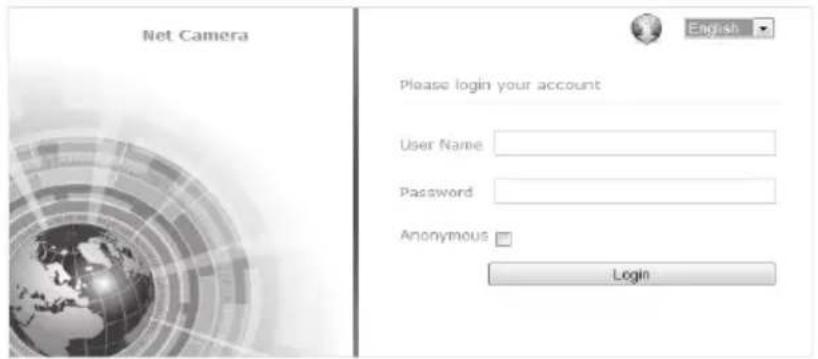
Image 2.2.1-1 Login
◆ Default user name: admin
◆ Default password: admin
◆ Default port: 8000
2.2.2 Download Video Player
After loginning successfully, please download the latest update with double-clicking the plug-in or the icon on the top right corner, if this is the first time the Browser logins or the icon finds a new version automatically.
Next, open the WebPluginInstaller.exe which has been downloaded and clicking "Next" till it finishes installation. At last, users should run this plug-in and refresh the Browser for watching the video.
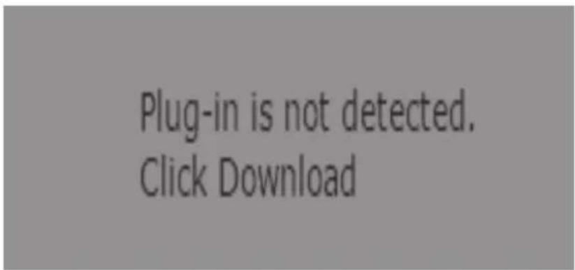
image2.2.2-1 plug-in
Caution: This plug-in must be installed for watching videos on Browsers. Till now, this video player supplies these operating systems: Windows XP, Windows 2000-2014, Windows Vista with 32-Bit or 64-Bit. The following examples are shown in Windows 7 and Explorer 11.
2.2.3 Live View
After installing the players, users should input the user name, password again for opening the interface of Live View, as Image 2.2.3-1 shows
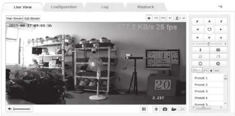
Image 2.2.3-1 Live View
| Icons | Explanation | ||
 | The scale of image is 4:3 | ||
 | The scale of image is 16:9 | ||
 | The scale of image is original | ||
 | The scale of image is adjusted automatically | ||
| Main Stream Sub Stream | Choose main stream or substream | ||
 | Audio Control | ||
 | Start/End two-way audio | ||
 | Capture | ||
 | Start / End the recording | ||
 | 3D Location | ||
 | PTZ Control | ||
| Main Stream | Sub Stream |
2.2.3-2 Live View information
| Icons | Explanation |
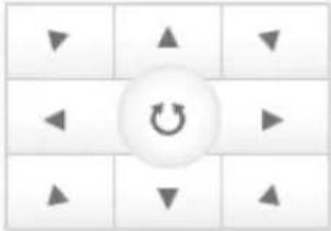 | Pan and Tilt Control; Turn on / off scanning automatically |
 | Zoom |
 | Focus |
 | Iris |
 | PTZ Speed |
 | Preset |
 | Patrol |
 | Pattern |
 | IR Setting |
 | Auto Scan |
2.2.3-3 PTZ Control information
In the interface of Live View, users could operate the live view, recording, screenshot, video chat and voice switch.
The scale of images could be adjusted to “Default”, “4:3”, “16:9”, or “Auto”.
The kind of stream could be adjusted to “Main Stream” or “Substream”, as Image 2.2.3-2 shows.
Clicking “PTZ Control”, then users could operate the interface of PTZ, as Image 2.2.3-3 shows.
Operating Method for setting the preset:
- Clicking "preset" and the screen would show the position where the camera is focusing now.
- Set the preset: Choose the number of preset and then operate the PTZ Control Panel. While the camera moves to the position needed, click "Save" for saving this position.
- Call the preset: Click "Call" for calling the preset which has been set.
- Delete the preset: Click "Clear" for deleting the preset.
5.presets for specification: These presets could be called, but not be changed or deleted.
Operating Method for setting the Patrol:
-
Set the preset: Refer to the steps in setting the preset above.
-
Choose the number of Patrol path: Choose the number of path needed, Path 1 for instance.
-
Add the preset: Add presets into the path, and adjust the corresponding patrol time and speed.
-
Save the patrol path: Click "Save".
-
Turn on or off the patrol: Click "Start" or "Stop".
-
Delete the patrol: Click "Delete".
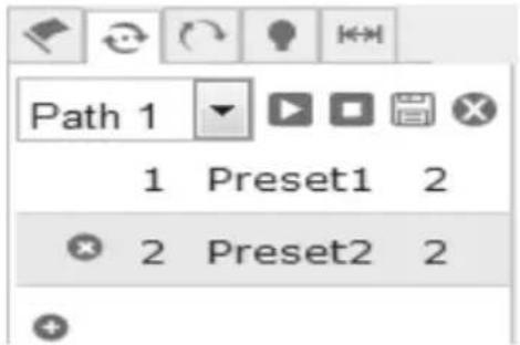
image2.2.3-4 Patrol setting
Operating Method for setting the Pattern:
- Open the interface of pattern, the screen would show the current path, as Image 2.2.3-5 shows.
2.Start Scan: Click "Start Recording" and operate the camera with PTZ Control Panel.
3.End Scan: Click "Stop Recording". - Turn on or off Scan: Click "Start" or "End".
- Delete the pattern: Click "Delete".

flowchart
graph TD
    A["Start Recording"] --> B["Stop Recording"]
    B --> C["Stop"]
    D["Star"] --> A
    E["Delete"] --> F["Stop Recording"]
Image 2.2.3-5 Scan
Browser
Operating Method of IR Setting:
Open the interface, and users could adjust dipped beam (Powers from 1 to 10), high beam, dipped compensation, illuminance, infrared according to the requests. The interface is
shown as Image 2.2.3-6.
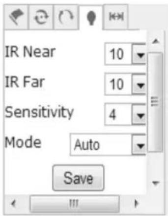
Image 2.2.3-6.IR Setting
Settings of Auto Scan:
Open the interface of Auto Scan, users could adjust scan speed, left margin, right margin, scan start, scan end; 8 paths could be used for auto scan, and the interface is shown as Image 2.2.3-7.
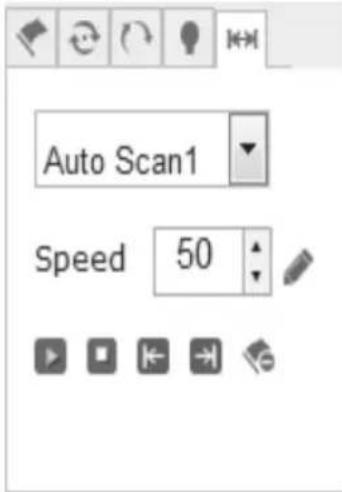
Image2.2.3-7 Auto Scan
- Scan Speed: From 1 to 100. Larger difference on numbers, More obvious on effects.
- Left margin and right margin: First, Stop the camera and click “Left Margin”. Then, Stop the camera and click “Right Margin”. Finally, click “Start Scan” and the camera would move in the range of margins. Click “Stop Scan” to stop the camera.
3.The operating methods for other paths in auto scan are the same.
2.2.4 Replay
Click “Playback” and open the interface. In the interface, users could search, replay or download any video files on the SD card which has been installed on the network camera
On the right side, users could choose types or Start/End time. Clicking “Search”, video files which are satisfied would be shown in the box on the right hand. Choose the file and download it, then users could replay the video by double-clicking it, as Image 2.2.4-1 shows
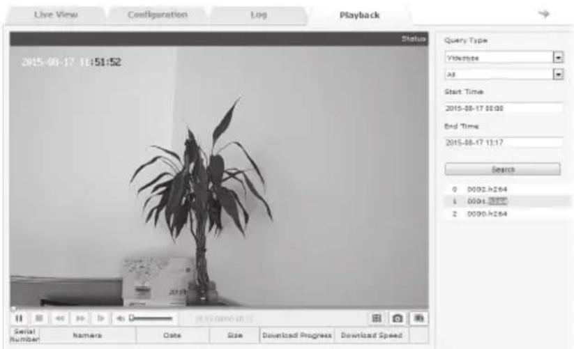
Image2.2.4-1 Replay
Caution: The prerequisite for Playback is that SD card was plugged in. Initializing the SD card and setting the video schedule in the option “Save” are needed for the first time with SD card plugged in.
2.2.5 Log
Click “Log” and open the interface. In this interface, users could search or read or output all available log files in the SD card installed on the network camera.
Choose the type and set the dates, then all log files satisfied would be shown on the list after clicking “Search”, as 2.2.5-1 shows. Click “Save” and the log files which was chosen would be saved to users’ computers
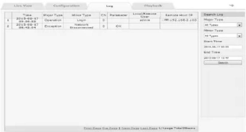
Image2.2.5-1 Log
2.2.6 Configuration
Click “Configuration” and open the interface, as Image 2.2.6-1 shows. Image 2.2.6-2 explains all parameters below.
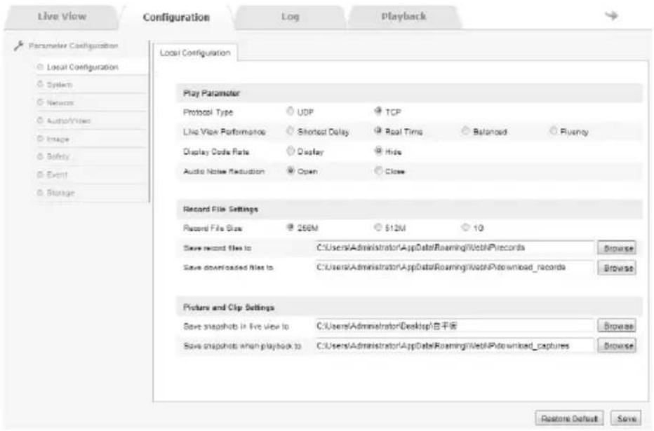
Image 2.2.6-1 Configuration
| Parameters | Explanation |
| Protocol Type | TCP or UDP |
| Live View Performance | Shortest Delay, Real Time, Balanced, Fluency |
| Display Code Rate | Display or Hide |
| Audio Noise Reduction | Open or Close |
| Record File Size | 256M、512M、1G |
| Save record files to | Custom Settings |
| Save downloaded files to | Custom Settings |
| Save snapshots in live view to | Custom Settings |
| Save snapshots when playback to | Custom Settings |
2.2.6-2 Local Configuration
System → Device Information
In this interface, users could set device name, model, serial number, program version, control version, web page version, plugin version, number of channels, disk quantity, number of alarm input, number of alarm, output, CPU, and memory, as Image 2.2.6-3 shows
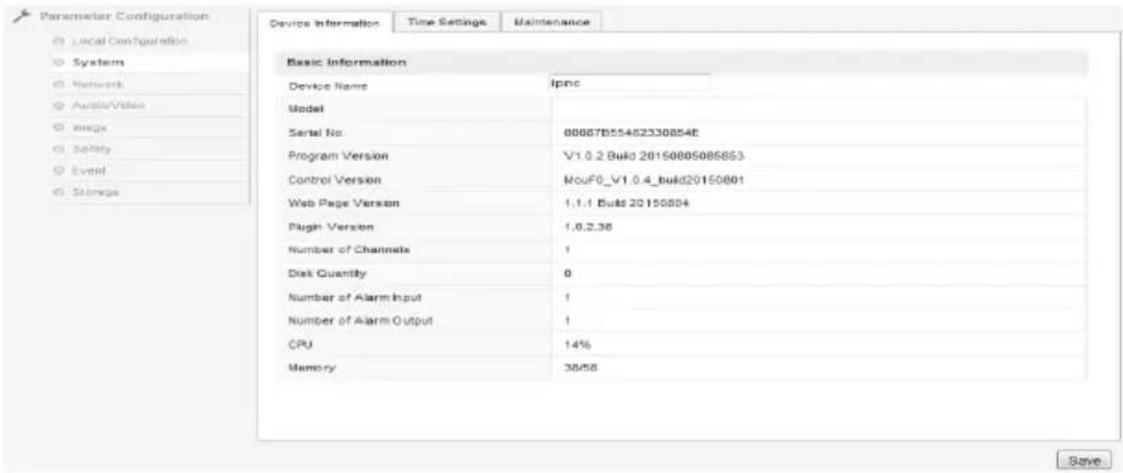
Image 2.2.6-3 Device Information
System→Time Settings
In this interface, users could configure time for the camera. Time Zone shows local time zone of the camera and it could be adjusted according to the requests. Users could also configure “Time sync.” by setting NTP server address, NTP port, and Interval. Click “Test” and it could check the availability of the server address. “Manual Time sync.” is also available for configuring time. Tick “Sync. with computer” and it would synchronize the network camera with the computer. By clicking “Save”, all changes would be saved, as 2.2.6-4 shows.
Caution: NTP Port could not be changed.
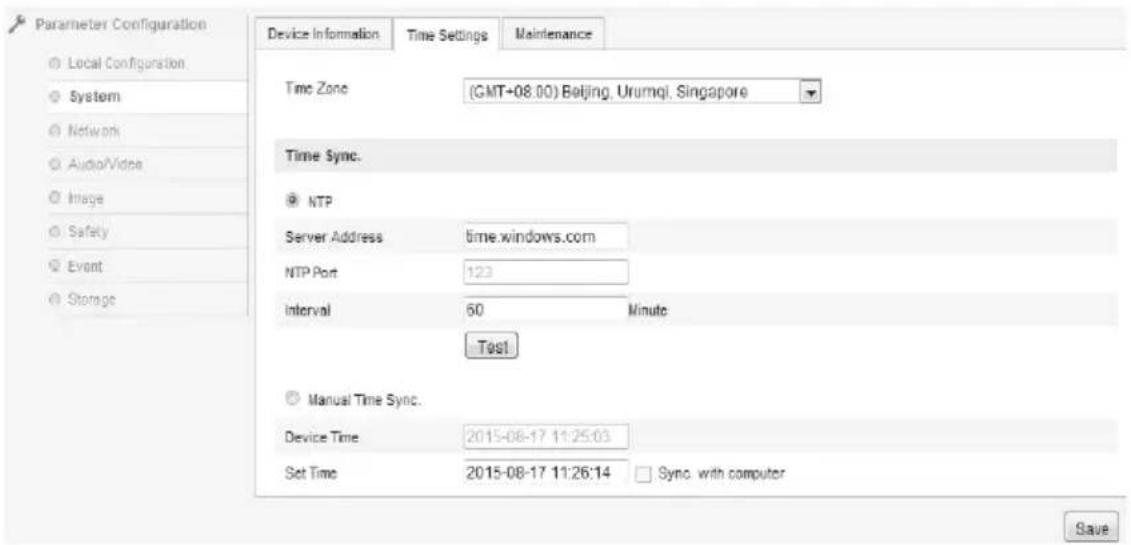
Image 2.2.6-4 Time Settings
System → Maintenance
Interface of Maintenance is shown as Image 2.2.6-5.
Reboot means reboot the device.
Restore means reset all the parameters, except the IP parameters and user's information, to the default settings.
Default means restore all parameters to default settings.
Import or Export Files would import or export corresponding configuration files.
(A warning saying “there is 59 seconds for switching to the login interface” would be shown after clicking the keys)
By clicking “Browse”, choosing local upgrade files or catalogs, and clicking “Upgrade”, users could upgrade the device’s version. Status shows the current progress and indicates the completion status after upgrading.
Caution: Do not turn off the power since network camera would restart automatically after upgrading successfully.
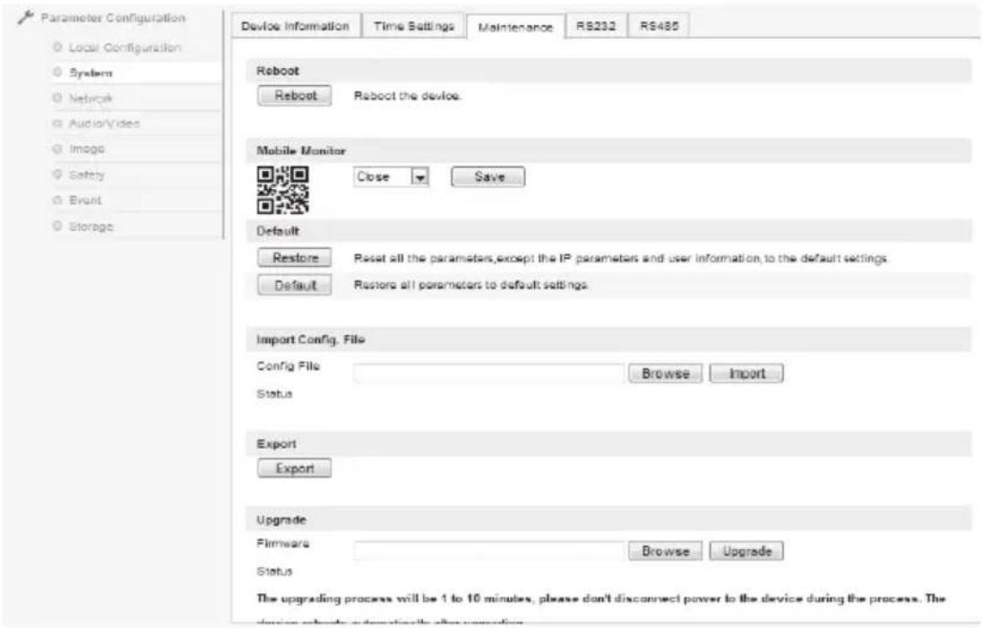
Image 2.2.6-5 System → Maintenance
Network →TCP/IP
In this interface, users could set IPv4 Address, IPv4 Subnet Mask, IPv4 Default Gateway, IPv4 DNS Server and IPv6 Mode of the camera. With ticking "Auto", the device could obtain IP Address automatically. Click "Save" for saving these settings, as Image 2.2.6-6 shows.
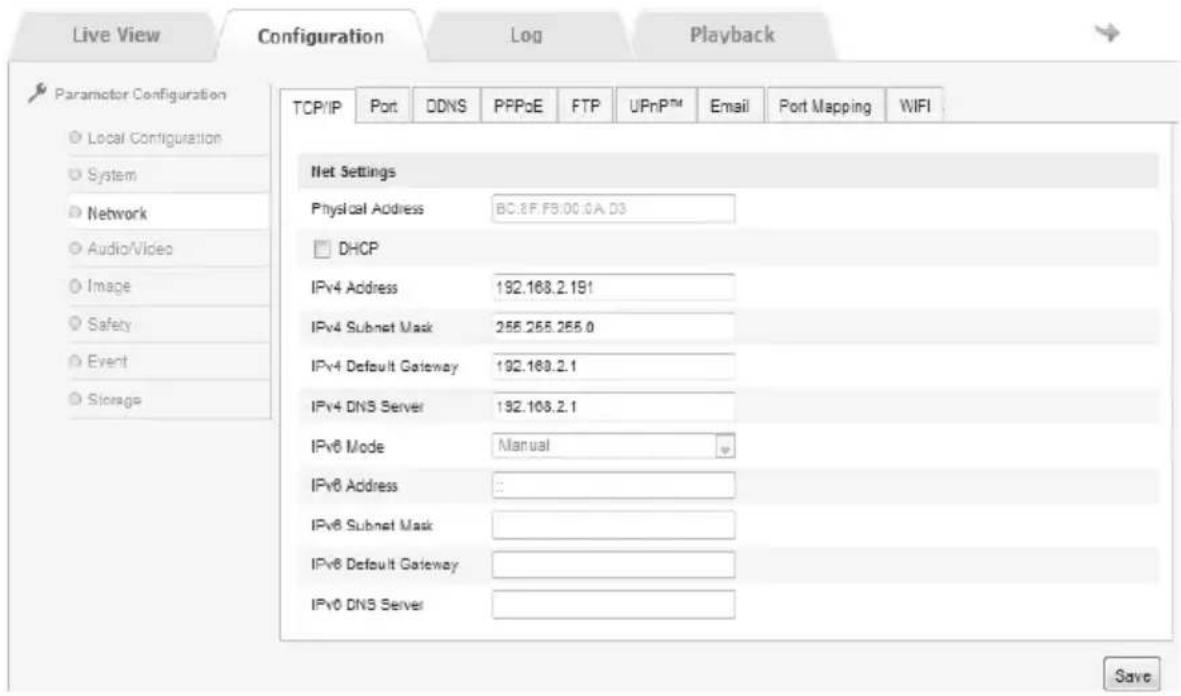
Image 2.2.6-6 TCP/IP configuration
Network→Port
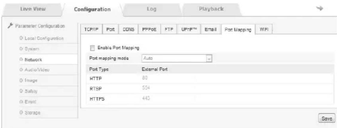
The parameters are HTTP Port (Default is 80), RTSP Port (Default is 554), and HTTPS Port (Default is 443). According to the requests, these ports could be adjusted. Click “Save” for saving these settings, as Image 2.2.6-7 shows.
Caution: Users should restart the network camera after setting the parameters
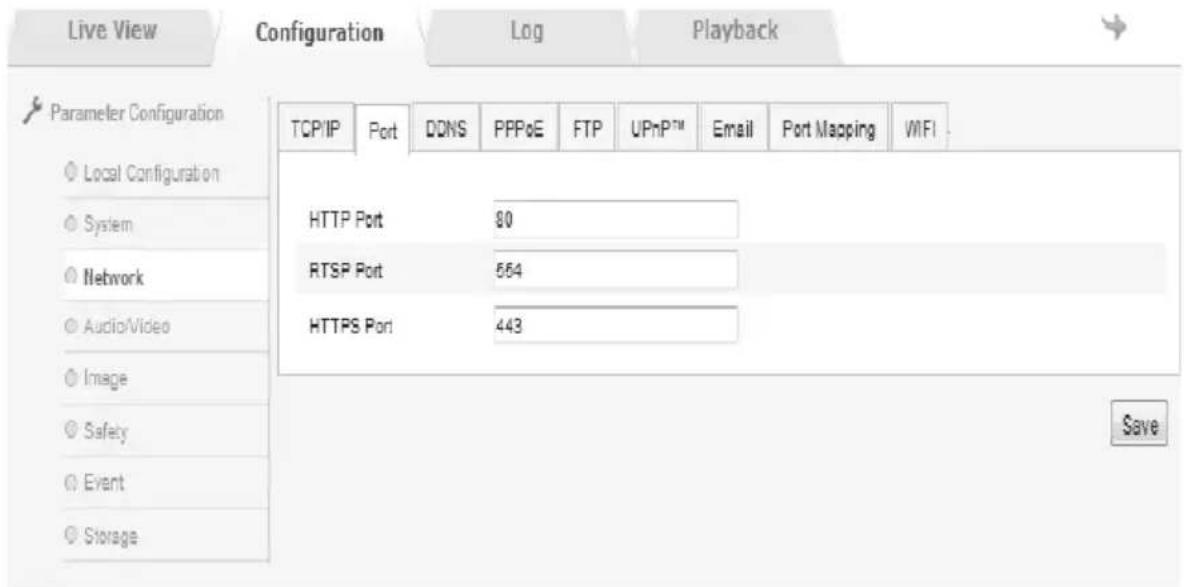
Image 2.2.6-7 Port configuration
Browser
Network→DDNS
Ticking “Enable DDNS” for turning on DDNS. Users could choose “Oray” or “Noip” as DDNS Type, as 2.2.6-8 shows.
The server address of operator is necessary in Oray which always turns on. Usually, server address is the one of software operator and domain is the one registered by users on the website of software operator. Ports could be adjusted according to the requests. Also, user name and password are the ones users using for login.
So does Noip.
Click "Save" for saving these settings after inputting parameters.
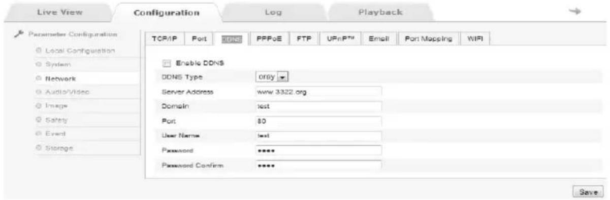
Image 2.2.6-8 DDNS setting
Network→PPPoE
Ticking “Enable PPPoE” means turning on PPPoE. By inputting User Name and Password and saving it, the camera would receive a Dynamic IP after restarting it.
Click "Save" for saving these settings after inputting parameters.
Caution: With turning on PPPoE, the default gateway is no longer available. Users should restart the network camera after setting the parameters
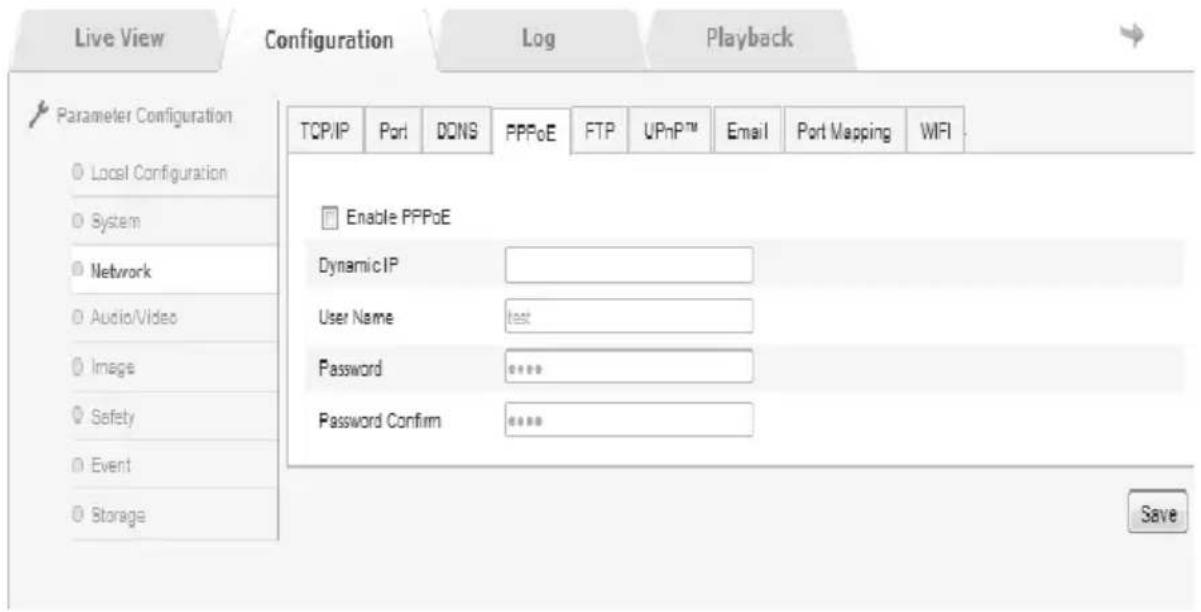
Image 2.2.6-9 PPPoE setting
Network→FTP
With adjusting FTP, users could upload the captured files to FTP server, as 2.2.6-10 shows.
Server address and port are Users' FTP server address and corresponding port.
Directory Structure could be adjusted for save path. “Save in the root directory”, “Save in the parent directory”, “Save in the child directory” could be chosen. In the parent directory, “Use Device Name”, “Use Device Number”, “Use Device IP” could be chosen. In the child directory, “Use Camera Name” and “Use Camera Number” could be chosen.
Ticking “Upload” could turn on the function of camera for uploading images. “Test” is for testing whether the connection is successful.
Click "Save" for saving these settings after inputting parameters.
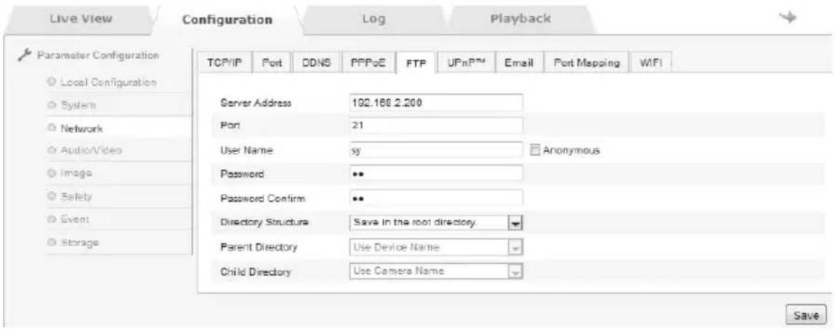
Image 2.2.6-10 FTP setting
Network→UpnP
This function realizes that the camera could be discovered in LAN. For a network camera in LAN, UPnP could match ports from gateways or routers to internal network.
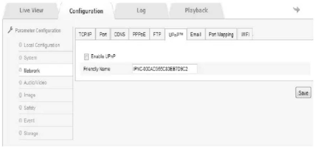
Image 2.2.6-11 UPnP setting
Network → Email
Users should input Sender, Sender Address, SMTP Server, SMTP Port, User Name, Password, Password Confirm, Receiver Name, and Receiver Address; and tick "Start SSL" or "Authentication", as Image 2.2.6-12 shows.
Caution: Users could not use Chinese characters for Sender and Receiver. The port of QQ Email is 25 and others' are 465. If users start SSL, user name would be the same as Sender Address.
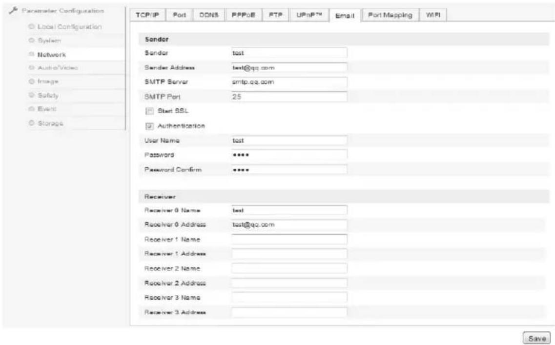
Image 2.2.6-12 Email setting
Turning on mapping port with ticking “Enable Port Mapping”, as Image 2.2.6-13 shows
Enable the WiFi, and set corresponding parameters for starting WiFi connection, as Image 2.2.6-14 shows
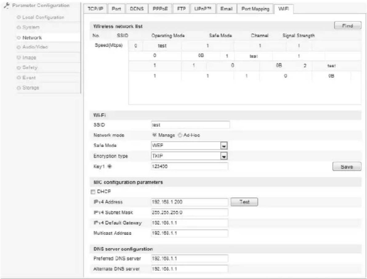
Image 2.2.6-14 Wifi setting
Audio/Video → Video
In this interface, users could set some parameters, such as stream type, resolution, and Max. Bit rate, as Image 2.2.6-15 shows. The details are shown as Image 2.2.6-16
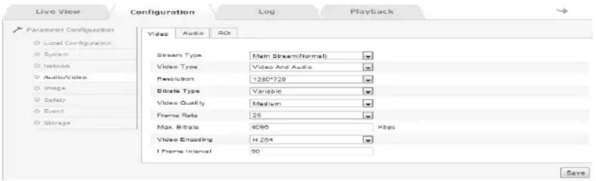
Image 2.2.6-15 Video setting
| Parameters | Explanation |
| Stream Type | Main Stream or Sub Stream |
| Video Type | Video Stream |
| Resolutio | 1920*1080 |
| Bit rate Type | Variable or Constant |
| Video Quality Lowest, Lower, Low, Medium, Higher, Highest | |
| Frame Rate | According to the requests |
| Max. Bit rate | According to resolution or custom |
| Video Encoding | According to the requests |
| I Frame Interval Frame rate | between two key frames (1-400) |
2.2.6-16 Video Configuration Explanation
Audio/Video→Video
Audio Encoding: G.711U
Audio Input: LineIn (if using active pick-up) or MicIn (if using passive microphone)
Input volume: The default is 50, but it could be set between 1 and 100.
Click “Save” for saving these settings after inputting parameters. The interface is shown as Image 2.2.6-17 and the details are shown as Image 2.2.6-17-1.
Caution: Users should restart the network camera after setting the parameters.
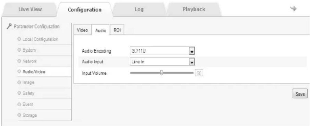
Image 2.2.6-17 Video setting
| Parameters | Explanation |
| Audio Encoding: | G.711ulaw |
| Audio Input | MicIn or LineIn |
| Input volume 0 | to 100 |
2.2.6-17-1 Parameters' Explanation
Audio/Video ROI
It could aggregate the streams so that the screen would describe areas more clearly,
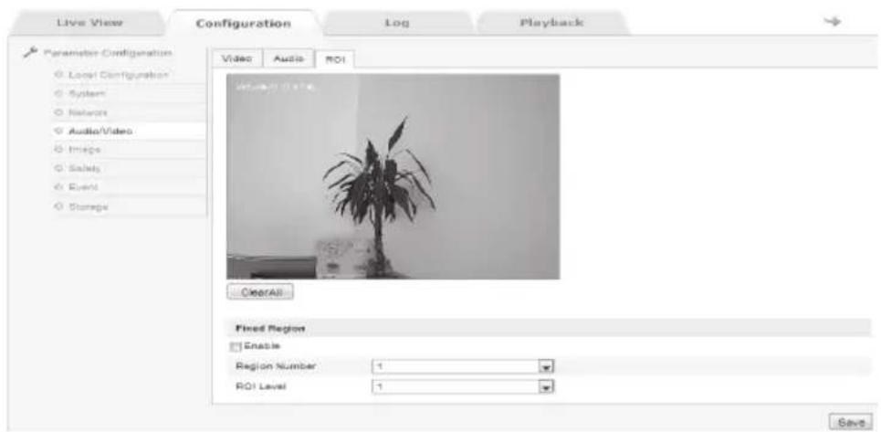
Image 2.2.6-18 ROI setting
Image → Display Settings
The interface is shown as Image 2.2.6-19, and the configuration is shown as Image 2.2.6-20.
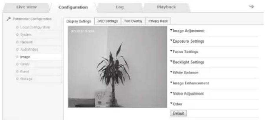
Image 2.2.7-19 Display Settings
| Parameters | Explanation |
| Brightness 0 to 100 | |
| Contrast 0 to 100 | |
| Contrast 0 to 100 | |
| Contrast 0 to 100 | |
| Hue On or Off | |
| Exposure Mode | Auto or Manual |
| Exposure Bias | On or Off |
| Compensation Level | 0 to 100 |
| Gain Limit 0 to 100 | |
| WDR On or Off | |
| White Balance | Auto or Manual |
| Digital Noise Reduc-tion | On or Off |
| 2DNoise Reduction | 0 to 100 |
| 3DNoise Reduction | 0 to 100 |
| Mirror Off, Up/Down, Left/Right, Center | |
| Video Standard | 50hz or 60hz |
2.2.6-20 Explanation of Parameters
Sharpness: Higher sharpness, Clearer margins of images; but does not mean better quality of images, since overhigh sharpness causes anamorphose.
Focus Mode: In “Auto”, the camera would focus automatically according to the change of surroundings. In “Semi-auto”, the camera would focus once after zooming, but not anymore if area changes again. In “Manual”, users should adjust the camera and focus by themselves.
Min. Focus Distance: If the distance between target and len is smaller than the setting distance, the shooting image would not be clear.
Exposure Mode: “Auto” or “Manual”. Compensation could only be adjusted if exposure compensation has been turned on.
Video Standard: “50Hz” and “60Hz” could be chosen according to different standards. It applies to some kinds of camera, and users need to restart the camera after setting it. 50Hz means 25 frames per second and 60Hz means 30 in real-time.
Mirror: Chooses “Left/Right”, “Up/Down”, and “Center” for switching directions of camera.
WDR: Chooses "Off" or "On".
BLC: The default is "Off". When background is too light, enabling BLC could solve the problem of the lack of exposure.
White Balance: Chooses “Manual” or “Auto”; “Manual” supplies adjustment of R and B.
Digital Noise Reduction applies to adjustment of level of noise, but it would weaken the performance of images at the same time.
Default: Restore all to the default.
Caution: Our product might only have some functions in the list. Please refer to the camera users bought. Users should restart the camera after changing some specific parameters.
Image → OSD Settings
Channel Name, Display Name and Display Date could be adjusted according to the requests. “12-hour time system” and “24-hour time system” could be chosen in Time Format. Also, (ymd), (mdy), (dmy), and others could be chosen in Date Format.
Click "Save" for saving these settings after inputting parameters, as Image 2.2.6-21 shows
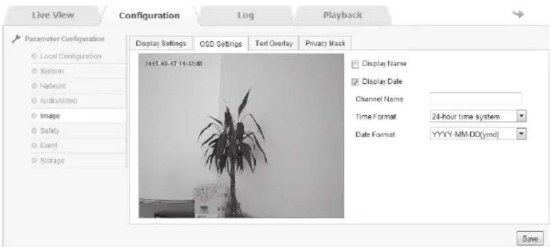
Image 2.2.6-21 OSD Setting
Image→Text Overlay
The camera supplies text overlay on the screen and the maximum number of characters is 40, as Image 2.2.6-22 shows.
Users could type words into the box, and tick corresponding serial number in order to preview the image. Users could also move characters shown on the screen with mice and save its position by clicking “Save”
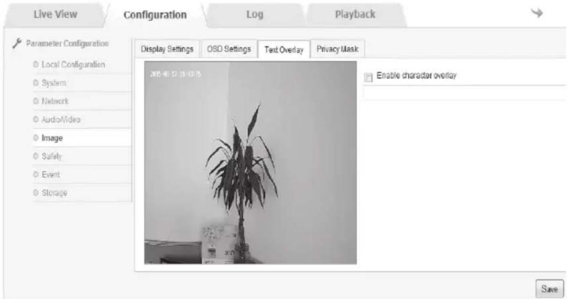
Image 2.2.6-22 Text Overlay
Image→ Privacy Mask
There are at most 4 areas which could be set after enabling the Privacy Mask, as Image 2.2.6-23 shows
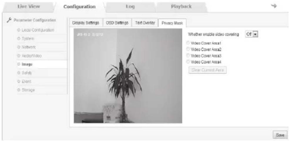
Image 2.2.6-23 Privacy Mask
Safety → User
In this interface, users could set users. While logging in with the administrator “admin”, users could create other users according to the requests. The quantity of users which could be added is 8, as Image 2.2.6-23 shows.
Add: With click “Addition”, the interface of adding user would be shown. Users should input user name and password, choose “Administrator”, “Observer”, or “User” in the list of Level, and click “OK” to confirm, as Image 2.2.6-24 shows.
Modify: Choose the user needed, click “Modify” to edit. In this interface, users could administrate this users’ user name, password and level. Both added users and edited users could set his “Basic Right” and “Channel Right” as well, as Image 2.2.6-25 shows.
Delete: Choose the user needed, click "Delete" to delete this user.
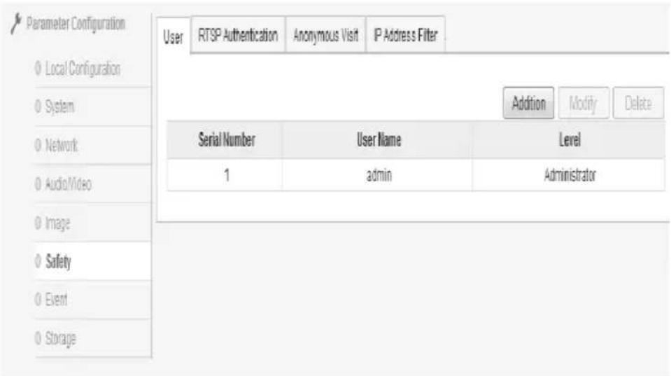
Image 2.2.6-23 User
Browser
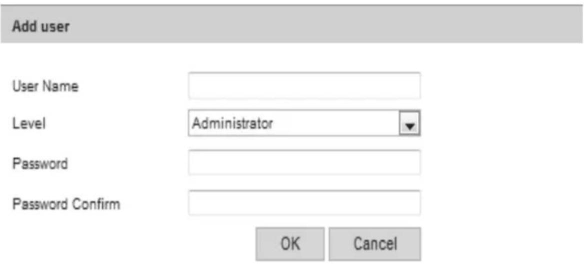
Image 2.2.6-24 Add user
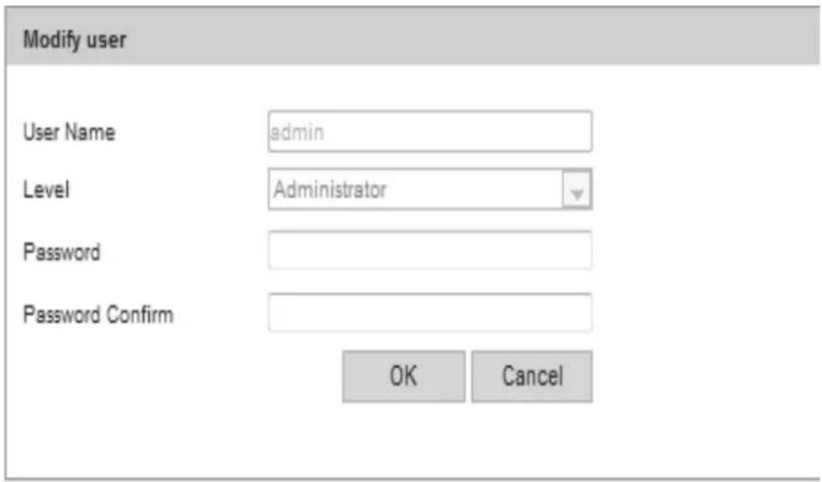
Image 2.2.6-25 Modify user
Safety → RTSPAuthentication
"Disable" and "Basic" could be chosen.
"Disable" means turning off RTSP Authentication.
“Basic” means turning on RTSP Authentication and authentication information is needed while sending requests to network camera.
Click "Save" for saving these settings after inputting parameters, as Image 2.2.6-26 shows
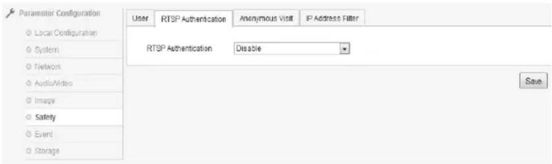
Image 2.2.6-26 RTSP setting
Safety→Anonymous Visit
“Enable” or “Disable” could be chosen. If enabled, anonymous visit is available while logging in.
Open the WEB interface individually, Option “Anonymous” would be shown in the login window if enabled; and users could login in directly without using User Name or Password.
If users login with “Anonymous”, they could check Live View only, as Image 2.2.6-27 shows.
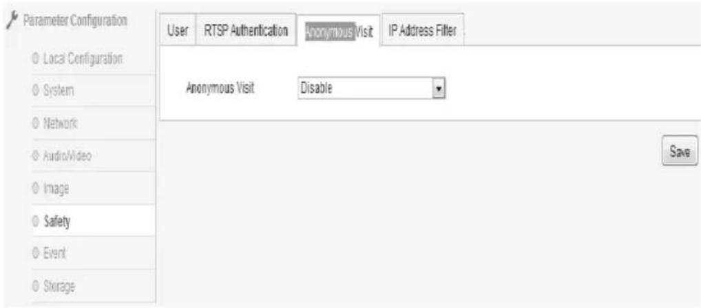
Image 2.2.6-27Anonymous Visit
Safety→IPAddress Filter
Users could turn it on with ticking "Enable IP Address Filter".
In Filter Type, “White List” or “Black List” could be chosen. “White List” means these IP Addresses could visit this camera; “Black List” means not.
Users could click “Addition” for adding new IP Address. For each IP Address, users could also operate it with clicking “Edit”, “Delete”, or “Clear”, as Image 2.2.6-28 shows.
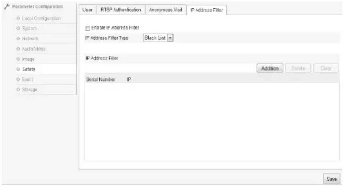
Image 2.2.6-28 IPAddress Filter
Event → Motion Detection
Ticking “Enable Motion Detection” is for turning it on, as Image 2.2.6-29 shows.
Area Setting: Click the left mouse button and move it in the screen; then release it for ending the drawing of an area. After all areas are drawn, users should set time and connection type for starting it.
“Clear All” would clear all areas drawn. Sensitivity: 0 to 100.
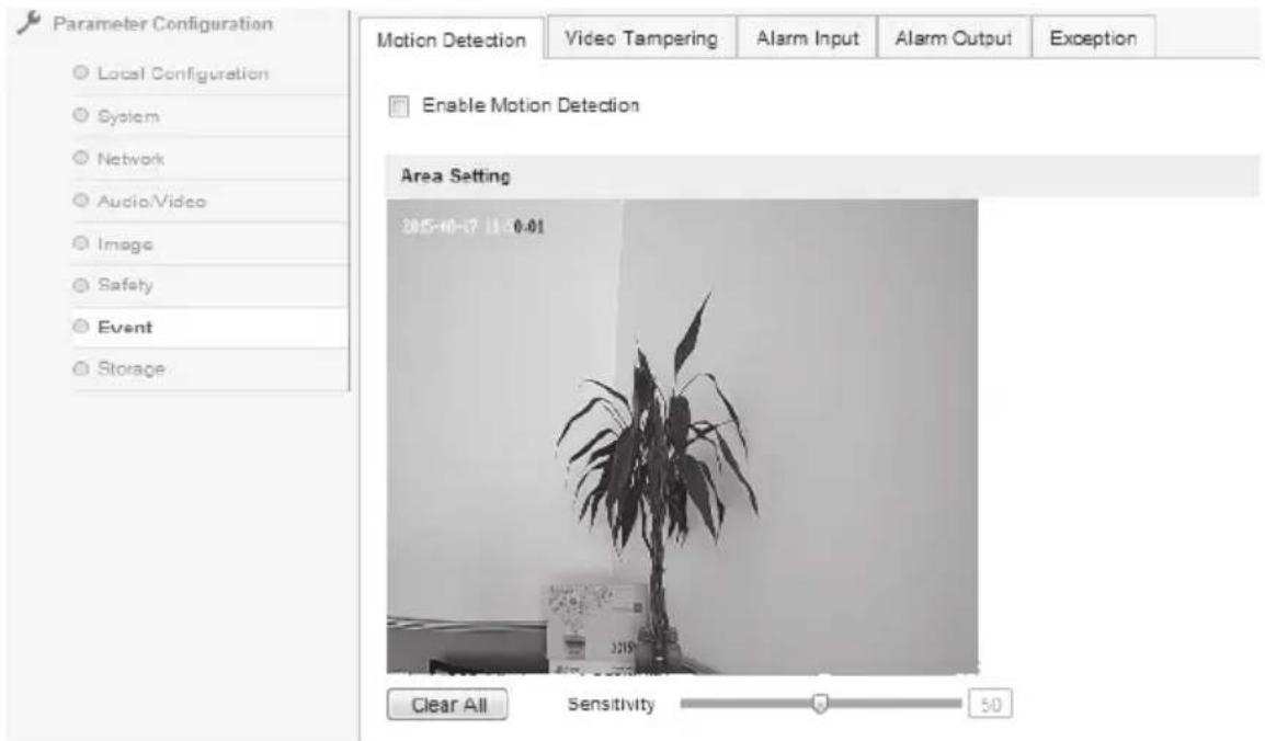
Image 2.2.6-29 Motion Detection
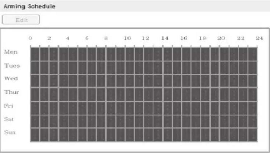
Alarming schedule would be shown in the option "Alarming Schedule".
With clicking “Edit”, users could adjust the alarming period. For instance, a whole week or one day could be used for a period. Totally, 4 periods could be used for adjustment, as Image 2.2.6-30 shows.
Click "Confirm" for saving these settings after inputting parameters.
| Linkage Method | |
| Normal Linkage | Other Linkage |
| ✓ Audible Warning ✓ Notify Surveillance Center ☐ Trigger Channel ☐ Capture ☐ Capture Upload FTP ☐ Capture Upload Mail ☐ Capture storage SD card | Trigger Alarm Output ☐ Select All ☐ A->1 |
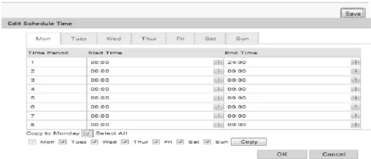
Image 2.2.6-30 Edit Schedule Time、Linkage Method
Event → Video Tampering
Ticking "Enable Video Tampering" is for turning it on, as Image 2.2.6-31 shows.
Area Setting: The default area is the whole screen.
Sensitivity: 0 to 100.
Click “Save” for saving these settings after inputting parameters. Other setting methods could refer to Image 2.2.6-30.
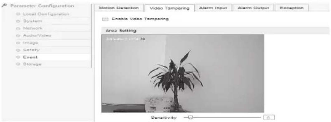
Image 2.2.6-31 Video Tampering
Event→Exception
“HDD Full”, “HDD Error”, “Network Disconnected”, and “IP Address conflict” could be chosen in exception type, as Image 2.2.6-32 shows.
Corresponding output channel could be chosen in "Other Linkage".
Click "Save" for saving these settings after inputting parameters.
Caution: “Voice Alarm” means the camera supplies voice alarm of alarming devices, like alertor.
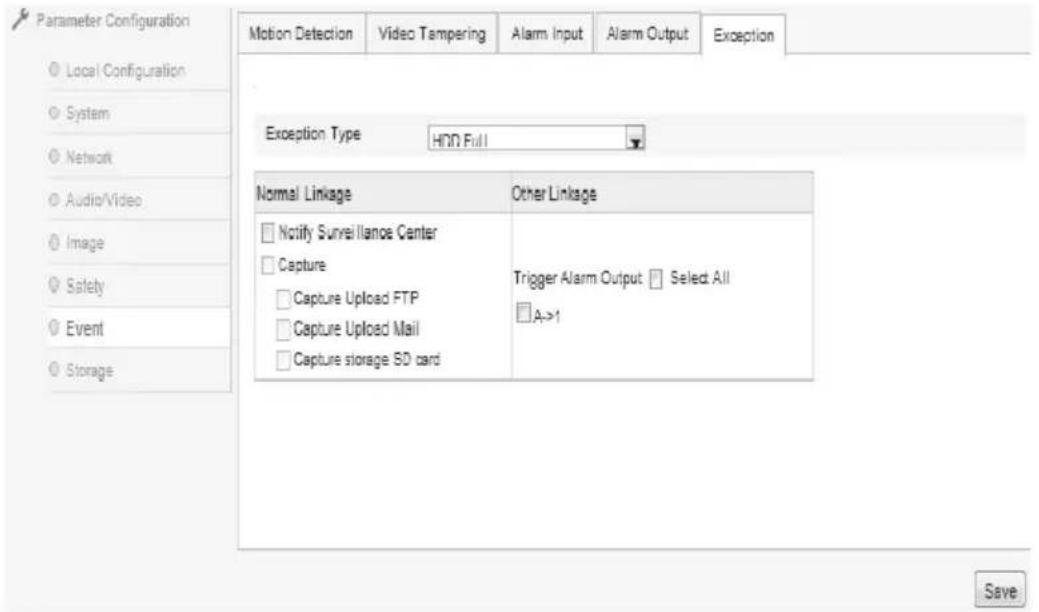
Image 2.2.6–32 Exception
Storage → Record Schedule
With ticking “Enable Record Schedule” and clicking “Editor”, users could edit the schedule, adjust periods, or choose types, as Image 2.2.6-33 shows. Schedule Setting is shown as Image 2.2.6-34.
“All Day” or “Section” could be chosen for recording schedule. If choosing “Section”, particular periods, 4 totally, are supplied for adjustment. If choosing “All Day”, “Timing”, “Motion Detection”, “Alarm”, “Motion or Alarm”, as well as “Motion and Alarm” could be chosen.
Pre-record means the period before recording. There are 8 levels in this option: 0 second to 30 seconds; and Not Limited.
Similarly, there are 7 levels could be chosen (from 5 seconds to 10 minutes) in the option "Post-record".
Click "Save" for saving these settings after inputting parameters.
Caution: Maximum pre-recording period is calculated in 2Mbps. Higher the stream chosen, shorter the pre-recording period.
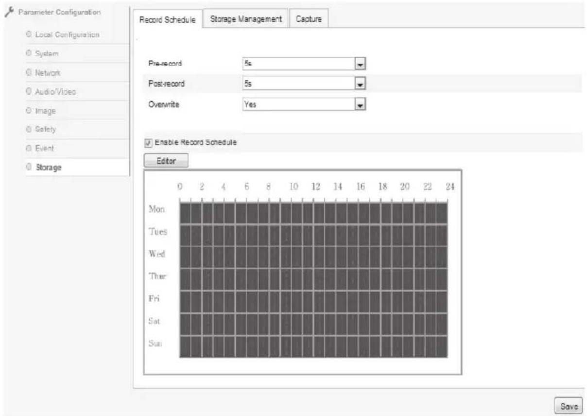
Image 2.2.6-33 Record Schedule
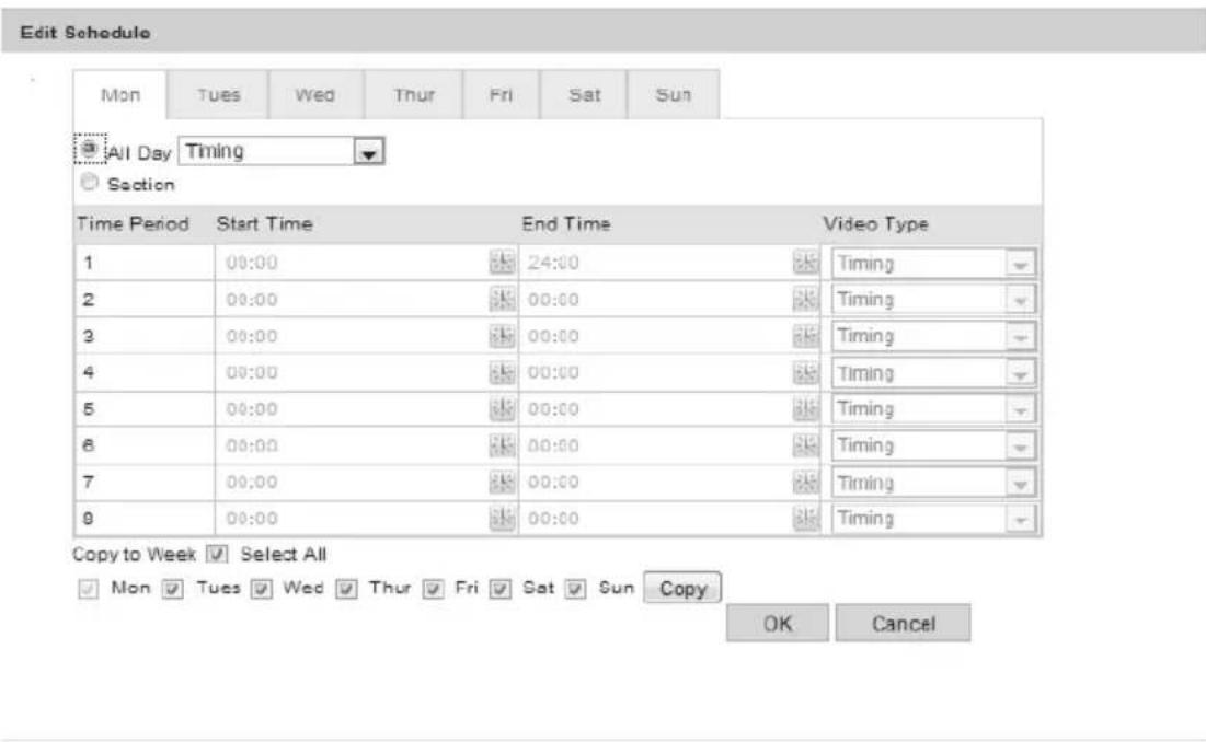
Image 2.2.6-34 Edit Schedule
Storage → Storage Management
Storage Management is used for checking devices' capacity and status. Users could initialize the device with ticking plugged-in TF cards and clicking "Format", as Image 2.2.6-35 shows.
HDD No.: The serial number of devices
Capacity: The capacity of devices
Free space: How much space could be used in devices
Status: The current status of devices
Format: Users could initialize the device
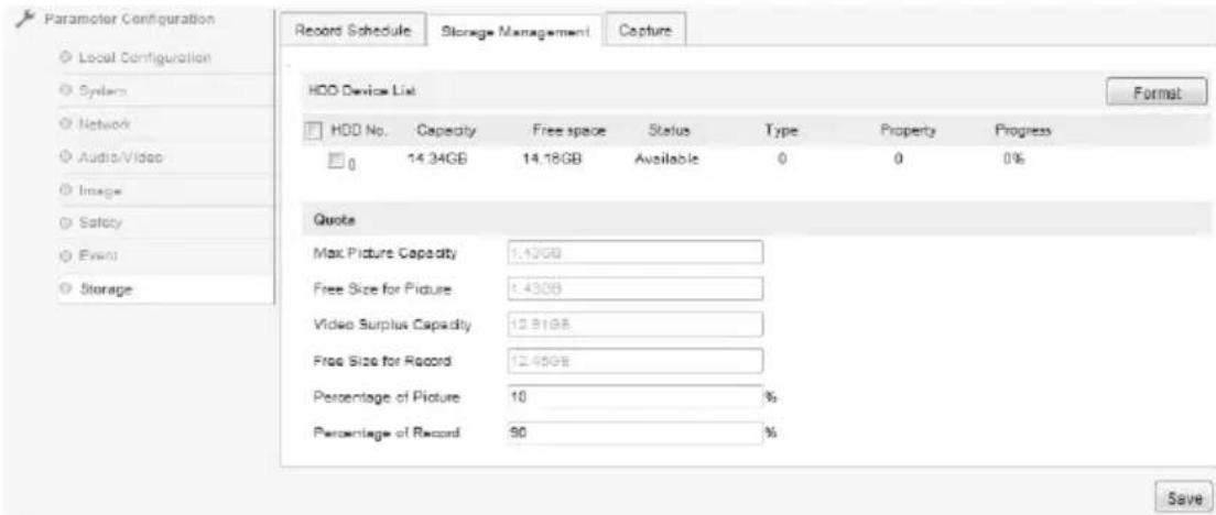
Image 2.2.6-35 Storage Management
Storage → Capture
Timing Snapshot is the only way for capturing, as Image 2.2.6-36 shows.
Format: JPEG
Resolution: Current resolution in main stream
Quality: Low, Middle, High
Interval: According to the requests, units are “millisecond”, “second”, “minute”, “hour”, or “day”. The available interval of capture is from 1 to 604800 milliseconds.
Click "Save" for saving these settings after inputting parameters.
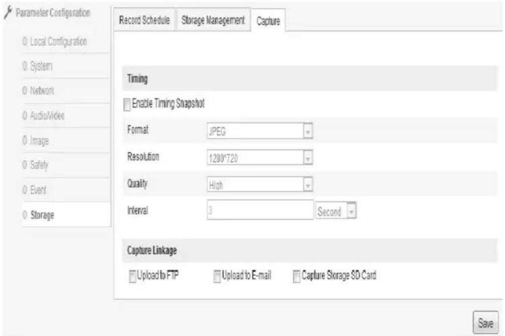
Image 2.2.6–36 Capture
3 Operation on Menu
3.1 System Information
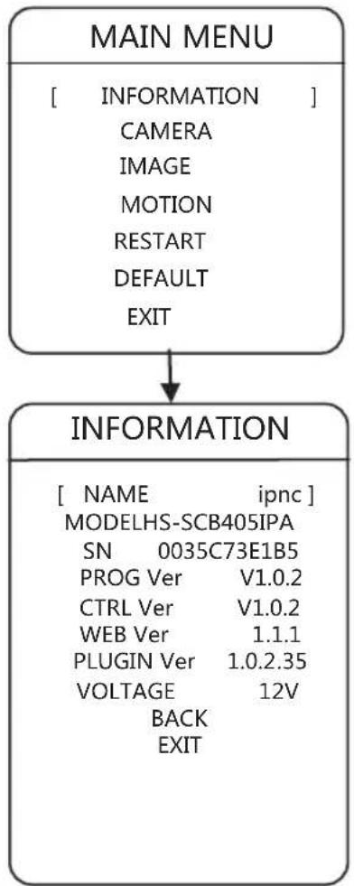
flowchart
graph TD
    A["MAIN MENU"] --> B["INFORMATION"]
    B --> C["[ NAME ipnc "]
MODELHS-SCB405IPA
SN 0035C73E1B5
PROG Ver V1.0.2
CTRL Ver V1.0.2
WEB Ver 1.1.1
PLUGIN Ver 1.0.2.35
VOLTAGE 12V
BACK EXIT]
According to the requests, users could check information on main menu. The information contains device name, model, SN, program version, control version, WEB version, plug-in version, and voltage.
"Up" and "Down" are used for choosing options, and "Left" and "Right" are used for checking current option.
3 Operation on Menu
3.2.1 Language
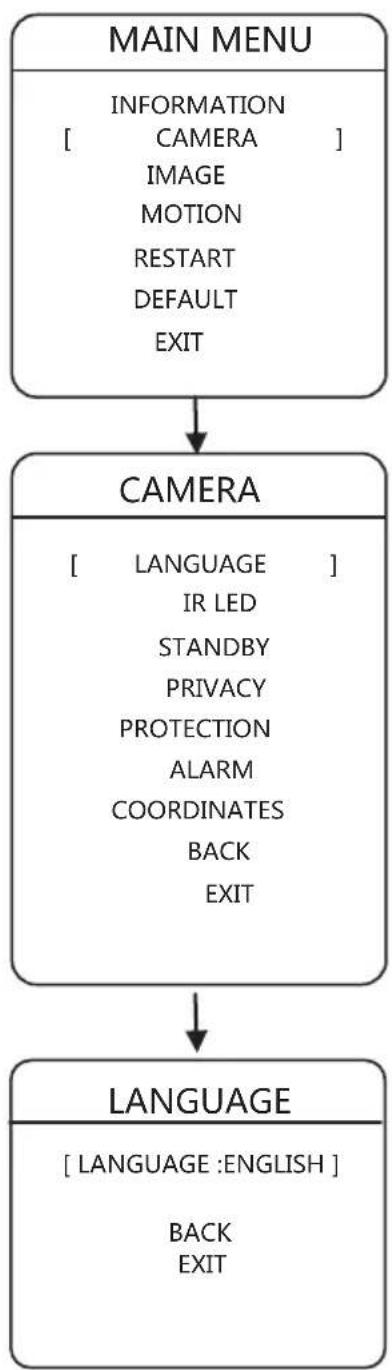
flowchart
graph TD
    A["MAIN MENU"] --> B["CAMERA"]
    B --> C["LANGUAGE"]
    C --> D["LANGUAGE :ENGLISH"]
    D --> E["BACK EXIT"]
Users could set the language, according to their requests. This camera supplies Chinese and English; and the default language is Chinese.
3 Operation on Menu
3.2.2 IR LED
flowchart
graph TD
    A["MAIN MENU"] --> B["CAMERA"]
    B --> C["IR LED"]
    C --> D["IR LED"]
    subgraph MAIN MENU
        E["INFORMATION<br>[ CAMERA "]
        IMAGE
MOTION
RESTART
DEFAULT
EXIT]
    end
    subgraph CAMERA
        F["LANGUAGE<br>[ IR LED "]
        IDLE
MASK
ALARM
OTHER
BACK
EXIT]
    end
    subgraph IR LED
        G["[ ILLUMINAINON 50 "]
MODE AUTO
SENSITIVITY 1
SWITCH DELAY 5
NEAW 10
FAR 10
BACK
EXIT]
    end
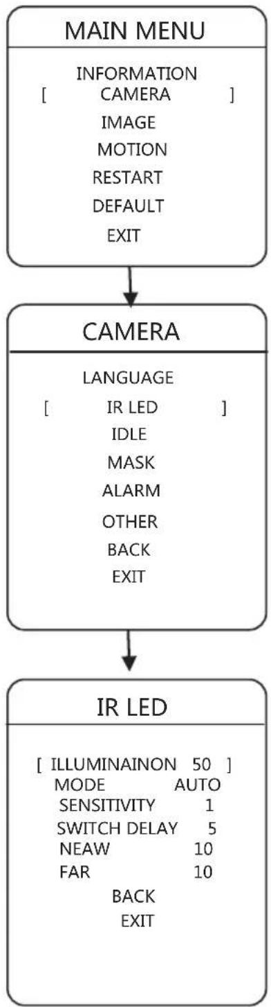
Users could adjust modes of IR LED on the menu, according to their requests.
ILLUMINATION: The device would show the value of brightness automatically.
MODE: AUTO: According to the surrounding brightness, the camera would turn it on or off.
OPEN: Turn it on
CLOSE: Turn it off
SENSITIVITY: If MODE is AUTO, the camera would check the sensitivity automatically. Smaller the number, Lower the illumination when IR LED is on.
SWITCH DELAY: 1 to 60 seconds.
NEAR POWER: 1 to 10
FAR POWER: 1 to 10
NEAR LIGHT COMPENSATION: 0 to 3.
When NEAR IR LED is on, distant light would be on according to the power settings.
Y
3 Operation on Menu
3.2.3 IDLE SETTING
flowchart
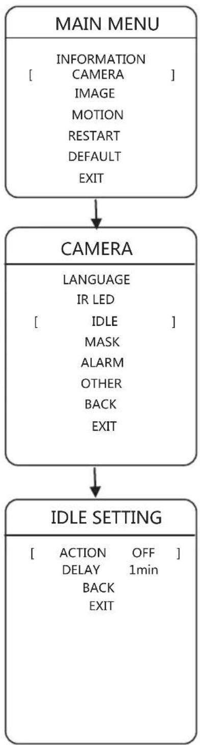
System architecture flowchart showing main menu, camera, and idle setting components with labeled interfacesUsers could adjust action and time when the device is standby, according to their requests.
STANDBY ACTION: "No action", "Preset 1", "Auto Scan", "Auto Patrol", "Pattern" could be chosen.
STANDBY TIME: Users could choose 1 minute, 5 minutes, or 10 minutes.
3 Operation on Menu
3.2.4 MASK
flowchart
graph TD
    A["MAIN MENU"] --> B["CAMERA"]
    B --> C["MASK"]
    C --> D["..."]
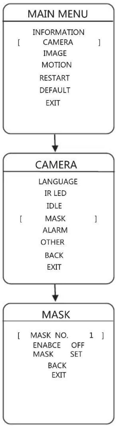
The network camera supplies privacy protection, and there are at most 4 areas which could be set.
Privacy Setting:
- Click "Far Focus" to confirm.
- When grey box appears, use "Left" or "Up" for zooming out; use "Right" or "Down" for zooming in.
- Click "Far Focus" or "Near Focus" to confirm after setting.
- Go back
3 Operation on Menu
3.2.5 ALARM
flowchart
graph TD
    A["MAIN MENU"] --> B["CAMERA"]
    B --> C["ALARM"]
    C --> D["ALARM MODE OFF"]
    C --> E["INPUT MODE N/C"]
    C --> F["ACTION OFF"]
    C --> G["ALARM OUT OFF"]
    C --> H["ALARM TYPE N/C"]
    C --> I["RESETDELAYMANUAL SCHEDULE"]
    C --> J["BACK EXIT"]
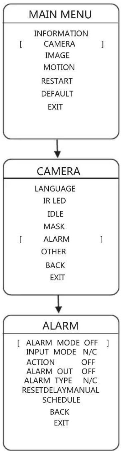
The network camera supplies 7 paths for alarm import and 1 path for export. While receiving the alarm, the alarm signal could trigger some functions needed, and match to the specific output at the same time.
INPUT MODE: Open usually: if channel is closed, the device receives available alarm signal.
Close usually: if channel is opened, the device receives available alarm signal.
ALARM MODE: Enable or Disable
ACTION: This function is used for determine whether some specific functions should be called while alarming, such as Preset 2 or No Action.
OUTPUT MODE: Users could use "Up" or "Down" to choose channels, such as opened, closed, or channel 1.
RESET DELAY: If ACTION is connecting with specific functions when alarm appears, the output switch would be off. RESET DELAY means the time period from receiving the alarm signal to resetting the alarm (output switch is off). 30 seconds, 1 minute, 5 minutes, or 10 minutes could be chosen in this option.
3 Operation on Menu
3.2.6 OTHER
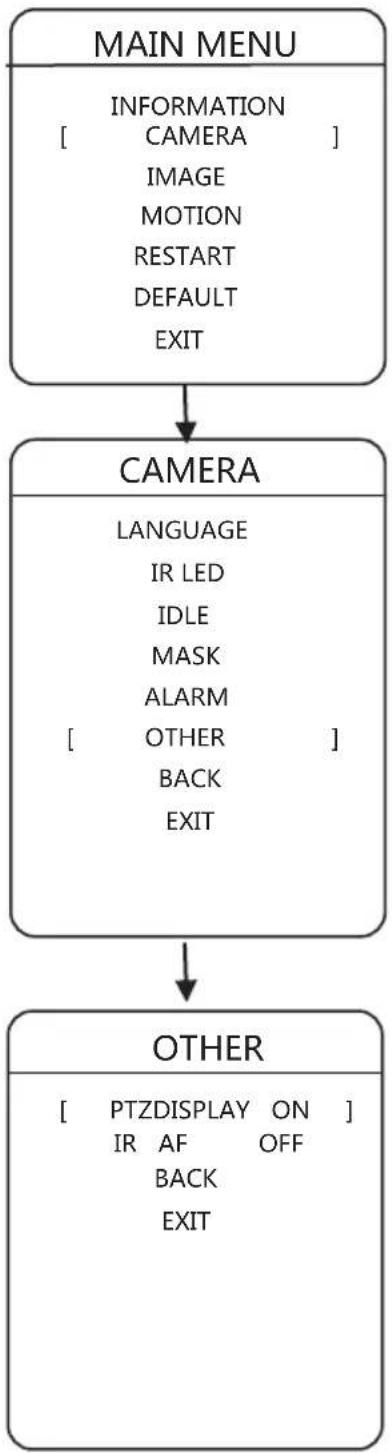
flowchart
graph TD
    A["MAIN MENU"] --> B["CAMERA"]
    B --> C["OTHER"]
Other could be on or off on the network camera
3
Operation on Menu
3.3.1 IMAGE ENHANCEMENT
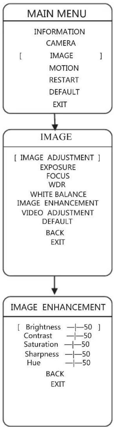
flowchart
graph TD
    A["MAIN MENU"] --> B["IMAGE"]
    B --> C["IMAGE ENHANCEMENT"]
    C --> D["IMAGE ENHANCEMENT"]
The network camera supplies image settings.
Brightness 0 to 100
Contrast 0 to 100
Saturation 0 to 100
Sharpness 0 to 100
Hue 0 to 100
3 Operation on Menu
3.3.2 Exposure
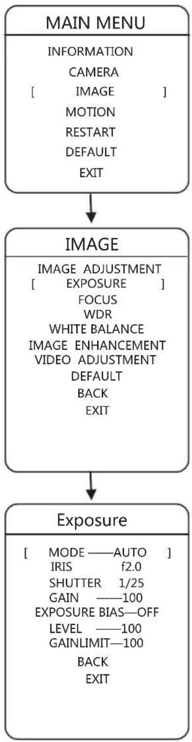
flowchart
graph TD
    A["MAIN MENU"] --> B["IMAGE"]
    B --> C["Exposure"]
    C --> D["TIME/ORDER"]
    D --> E["TIME/ORDER"]
    E --> F["TIME/ORDER"]
    F --> G["TIME/ORDER"]
    G --> H["TIME/ORDER"]
    H --> I["TIME/ORDER"]
    I --> J["TIME/ORDER"]
    J --> K["TIME/ORDER"]
    K --> L["TIME/ORDER"]
    L --> M["TIME/ORDER"]
    M --> N["TIME/ORDER"]
    N --> O["TIME/ORDER"]
    O --> P["TIME/ORDER"]
    P --> Q["TIME/ORDER"]
    Q --> R["TIME/ORDER"]
    R --> S["TIME/ORDER"]
    S --> T["TIME/ORDER"]
    T --> U["TIME/ORDER"]
    U --> V["TIME/ORDER"]
    V --> W["TIME/ORDER"]
    W --> X["TIME/ORDER"]
    X --> Y["TIME/ORDER"]
    Y --> Z["TIME/ORDER"]
    Z --> AA["TIME/ORDER"]
    AA --> AB["TIME/ORDER"]
    AB --> AC["TIME/ORDER"]
    AC --> AD["TIME/ORDER"]
    AD --> AE["TIME/ORDER"]
    AE --> AF["TIME/ORDER"]
    AF --> AG["TIME/ORDER"]
    AG --> AH["TIME/ORDER"]
    AH --> AI["TIME/ORDER"]
    AI --> AJ["TIME/ORDER"]
    AJ --> AK["TIME/ORDER"]
    AK --> AL["TIME/ORDER"]
    AL --> AM["TIME/ORDER"]
    AM --> AN["TIME/ORDER"]
    AN --> AO["TIME/ORDER"]
    AO --> AP["TIME/ORDER"]
    AP --> AQ["TIME/ORDER"]
    AQ --> AR["TIME/ORDER"]
    AR --> AS["TIME/ORDER"]
    AS --> AT["TIME/ORDER"]
    AT --> AU["TIME/ORDER"]
    AU --> AV["TIME/ORDER"]
    AV --> AW["TIME/ORDER"]
    AW --> AX["TIME/ORDER"]
    AX --> AY["TIME/ORDER"]
Exposure contains mode, iris, shutter, gain, exposure bias, level, and gain limit.
MODE: AUTO, MANUAL, IRIS FIRST, SHUTTER FIRST
EXPOSURE BIAS: ON or OFF
LEVEL: 0 - 100
GAIN LIMIT: 0 - 100
3 Operation on Menu
3.3.3 Focus
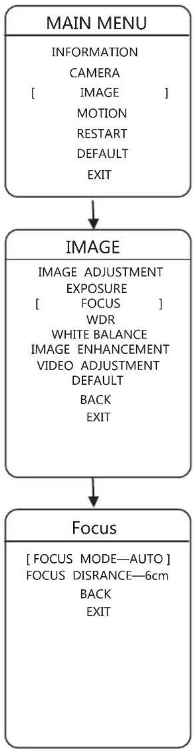
flowchart
graph TD
    A["MAIN MENU"] --> B["IMAGE"]
    B --> C["Focus"]
MODE: AUTO, MANUAL, KEYBOARD CTRL
DISTANCE: 10cm, 30cm, 1m, 1.5m, 3m, 6m, or INFINITE.
3 Operation on Menu
3.3.4 WDR
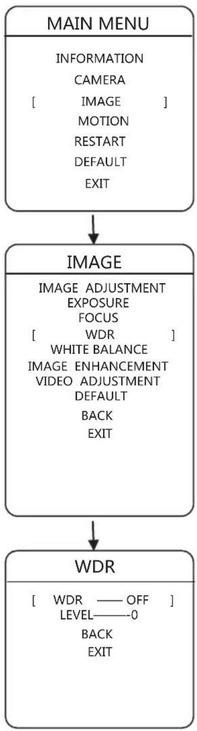
flowchart
graph TD
    A["MAIN MENU"] --> B["IMAGE"]
    B --> C["WDR"]
    A -->|INFORMATION\nCAMERA\n[" IMAGE "]\nMOTION\nRESTART\nDEFAULT\nEXIT| A
    B -->|IMAGE ADJUSTMENT\nEXPOSURE\nFOCUS\n[" WDR "]\nWHITE BALANCE\nIMAGE ENHANCEMENT\nVIDEO ADJUSTMENT\nDEFAULT\nBACK\nEXIT| B
    C -->|WDR — OFF\nLEVEL——0\nBACK\nEXIT| C
WDR: ON or OFF
LEVEL: 0 - 100
3 Operation on Menu
3.3.5 White Balance
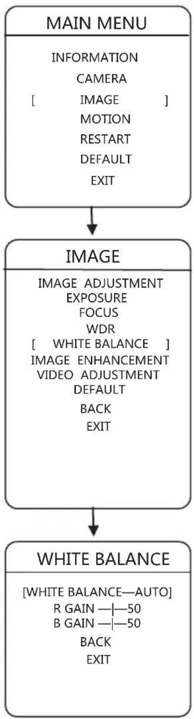
flowchart
graph TD
    A["MAIN MENU"] --> B["IMAGE"]
    B --> C["WHITE BALANCE"]
    C --> D["WHITE BALANCE—AUTO"]
WHITE BALANCE: ON or OFF
R GAIN: 0 - 100
B GAIN: 0 - 100
3 Operation on Menu
3.3.6 Image Enhancement
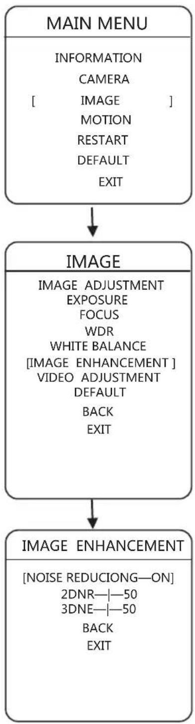
flowchart
graph TD
    A["MAIN MENU"] --> B["IMAGE"]
    B --> C["IMAGE ENHANCEMENT"]
    C --> D["IMAGE"]
NOISE REDUCTION: ON or OFF 2DNR: 0 - 100 3DNR: 0 - 100
3 Operation on Menu
3.3.7 Video Adjustment
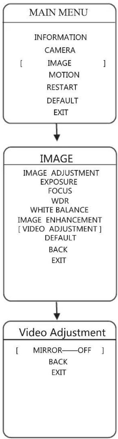
flowchart
graph TD
    A["MAIN MENU"] --> B["IMAGE"]
    B --> C["Video Adjustment"]
    C --> D["Output: Mirror—OFF, BACK, EXIT"]
MIRROR: OFF, CENTER, VERTICAL, or HORIZONTAL
3 Operation on Menu
3.3.8 Default
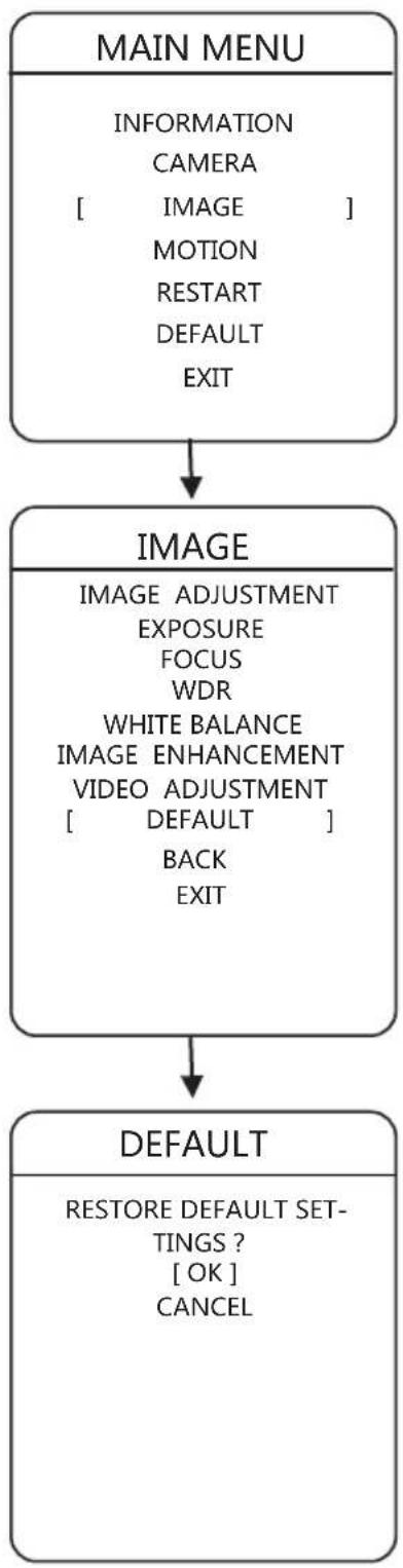
flowchart
graph TD
    A["MAIN MENU"] --> B["IMAGE"]
    B --> C["DEFAULT"]
    A -->|INFORMATION_CAMERA[" IMAGE "] MOTION RESTART DEFAULT EXIT| C
    B -->|IMAGE_ADJUSTMENT_EXPOSURE_FOCUS_WDR_WHITE_BALANCE_IMAGE_ENHANCEMENT_VIDEO_ADJUSTMENT[" DEFAULT "] BACK EXIT| C
    C --> D["RESTORE DEFAULT SETTINGS ? [OK"] CANCEL]
With clicking "Confirm", all parameters of image would restore to the default. To go back, click "Cancel"
3 Operation on Menu
3.4.1 Scan
flowchart
graph TD
    A["MAIN MENU"] --> B["MOTION"]
    B --> C["SCAN"]
    C --> D["SCAN NO.—1"]
    C --> E["SCAN SPEED—0"]
    C --> F["LEFT LIMIT SET"]
    C --> G["RIGHT LIMIT SET"]
    C --> H["SCAN START"]
    C --> I["BACK"]
    C --> J["EXIT"]
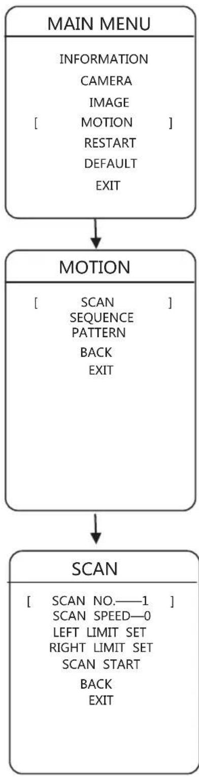
Scan is action of the network camera which moves between left margin and right margin. 8 auto-scan paths are supplied for each camera.
SCAN No.: To choose the serial number, click "Left" or "Right".
SCAN SPEED: 1 - 100
LEFT LIMIT SET: Users could control the camera to the position needed, then click "Focus" for saving this position as LEFT LIMIT.
RIGHT LIMIT SET: Users could control the camera to the position needed, then click “Focus” for saving this position as RIGHT LIMIT.
SCAN START: Start the scan for corresponding serial number.
3 Operation on Menu
3.4.2 Sequence
flowchart
graph TD
    A["MAIN MENU"] --> B["MOTION"]
    B --> C["SEQUENCE"]
    C --> D["..."]
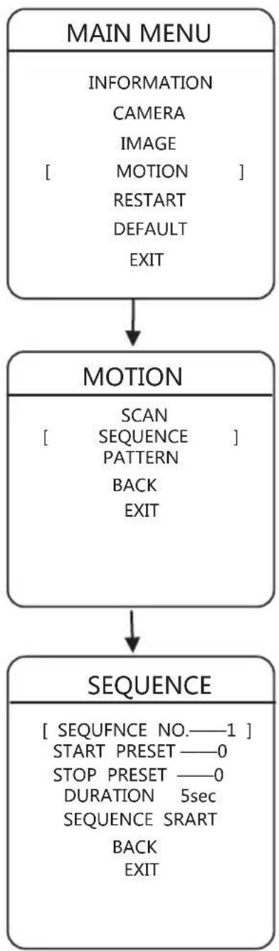
Sequence is switch among areas which was set and the period could be set by users. The network camera supplies 8 patrol paths and each path supplies 32 presets at most.
SEQUENCE No.: To choose the serial number, click "Left" or "Right".
START PRESET: To choose the start position, click "Left" or "Right".
STOP PRESET: To choose the stop position, click "Left" or "Right".
DURATION: To choose the duration, click "Left" or "Right".
SEQUENCE START: Start the patrol for corresponding serial number.
3 Operation on Menu
3.4.3 Pattern
flowchart
graph TD
    A["MAIN MENU"] --> B["MOTION"]
    B --> C["PATTERN"]
    A -->|INFORMATION\nCAMERA\nIMAGE\nMOTION\nRESTART\nDEFAULT\nEXIT| B
    B -->|SCAN\nSEQUENCE\nPATTERN\nBACK\nEXIT| C
    C -->|PATTERN—1\nPATTERN SET\nPATTERN DELETE\nPATTERN START\nBACK\nEXIT| C
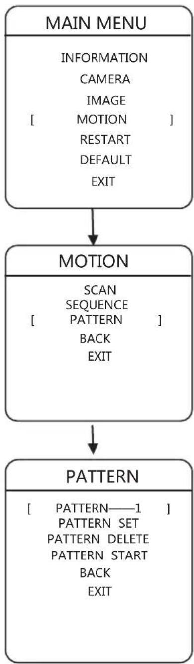
Pattern is the process of recording a series of operation by users in cameras. Users could start the scan pattern for replaying the operation users did. The camera supplies 4 patterns, and each pattern supplies 500 orders or 10-minute operation.
PATTERN No. : To choose the serial number, click "Left" or "Right".
PATTERN START: Start the scan pattern for corresponding serial number.
PATTERN SET: To set the pattern, click "Left" or "Right". Every moves, including pan or tilt turns and zooming, would be recorded in the camera. The setting of pattern would stop if the space is full or users click "Far Focus".
PATTERN DELETE: Delete the scan pattern for corresponding serial number.
3 Operation on Menu
3.5 Restart
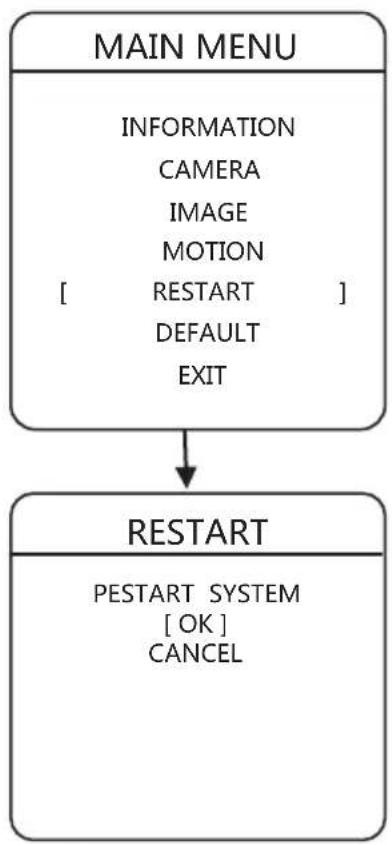
flowchart
graph TD
    A["MAIN MENU"] --> B["INFORMATION\nCAMERA\nIMAGE\nMOTION\n[ RESTART "]\nDEFAULT\nEXIT]
    B --> C["RESTART\nPESTART SYSTEM\n[OK"]\nCANCEL]
Users could restart the camera in menu with the following steps:
Go into “Restart” in menu, and restart the camera with clicking “Left” or “Right”. If users click “Left” or “Right” on “Cancel”, the operation of restart would be stopped.
3 Operation on Menu
3.6 Default
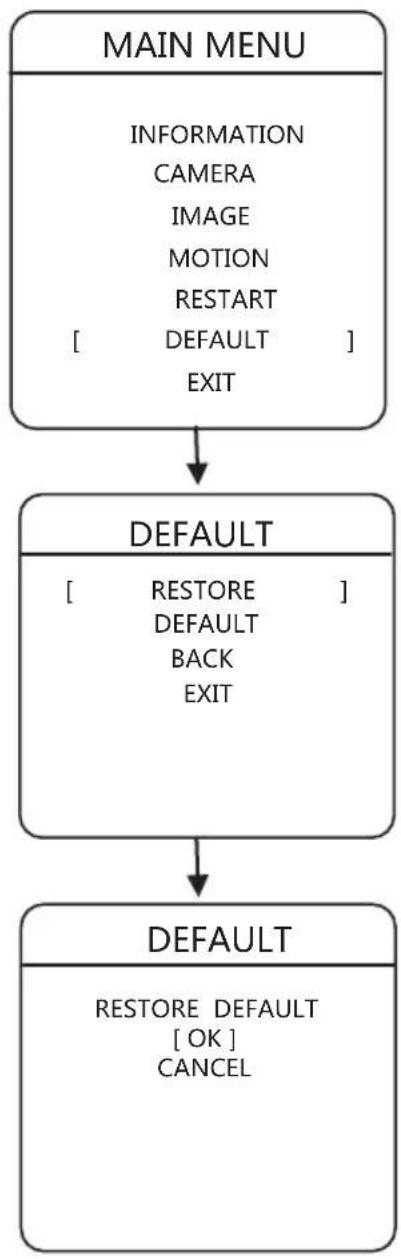
flowchart
graph TD
    A["MAIN MENU"] --> B["DEFAULT"]
    B --> C["DEFAULT"]
    C --> D["RESTORE DEFAULT BACK EXIT"]
    D --> E["RESTORE DEFAULT [OK"] CANCEL]
Default contains simple default and full default.
Simple Default: Restore all settings, except gateway, IP, subnet mask, and DNS server, to the default.
Full Default: Restore all settings to the default
To use simple default or full default, users could click “Left” or “Right” on “Simple Default” or “Full Default”. If users click “Left” or “Right” on “Back” or “Exit”, the operation of default would be stopped.
4 Customer Service
All network IR cameras produced in our company are under warranty in one year. If products are under warranty, we supply free maintenance and service. However, users need to pay extra fee if their products have the following cases:
Damages on products by incorrect or illegal operation.
Damages by force majeure, such as lightning or fire.
Damages on matching with other components produced by other manufacturers.
Statements
*New announcements would not be shown if there are some changes in parameters since we are applying new technique.
*The right of final explanation is reserved.
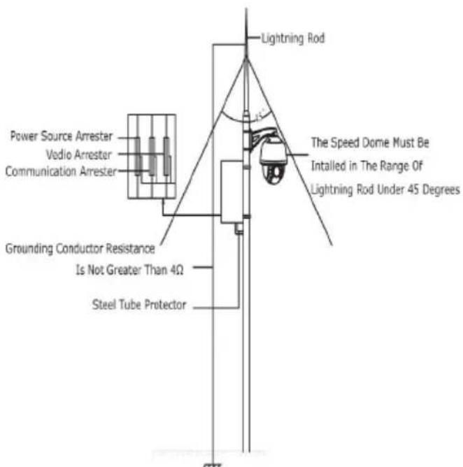
Figure 6.1 Installation Diagram
User Name : ____
Address : ____
If you have other requests, please write it down:
Appendix 1: Protection of Lightning and Waves
The camera supplies protection circuit combined with gas-discharged tube and TVS tube which could protect our camera from instant lightning below 3.0 kV and other impulse signals. However, in the prerequisite of safety of electricity and gases, the following protection methods are necessary, according to the reality.
The distance between signal transmission wires and high-voltage devices or cables must be longer than 50 meters.
Wires should be located under the eaves as far as possible if it is placed outside.
In the open field, wires should be placed in steel pipes under the ground hermetically. Besides, pipes must connect to the ground instead of placing without foundations.
In the area of thunderstorm or high-induced-voltage, like power plants, extra protection devices or lightning rods are necessary to install.
The design of outdoor device and wire protection must obey national standards, besides the requests of lightning protection of buildings.
The system should connect to the ground with equal potentials. The device must satisfy double requests of counter-jamming and safety of electricity and gases. Also, it should not be connected with neutral line. While the system is connecting to the ground, impedance on the ground should not be larger than 4 .
Appendix 2: FAQ
- Why couldn't I control the network camera?
You should check whether control agreement, address, and bit rate in RS485 on IE a matching to ones in network decompiler.
- My device connected successfully with using IE or Client, but it could not show the images (Blank Screen). What should I do?
You should check whether there exists a computer in the network whose IP Address the same as this network camera, then check whether the installation of graphics card driv DirectX is correct.
3.How to connect with audio-monitor?
Please use active detectophone or active microphone to connect with the interface of In, and use active loudspeaker to connect with the interface of A-out.
- The quantity of my cameras is over 250. How should I distribute the IP Addresses?
Second-type-IP is a good choice. For instance, 10.0.0.1 (Subnet Mask: 255.255.255.0) is the one you could use. For more information, please contact with your network adminis tor.
5.I have received two network cameras. Why could the first one be visited, but the ot not?
For testing conveniently, the IP Addresses of these two cameras are 192.168.0.99 both, but MAC Addresses are different. The operating system would save the IP and MAC Addresses from the former, which means the latter, whose IP Address is the same, might not be visited.
natural_image
Abstract grayscale gradient background with curved white and gray tones (no text or symbols)
natural_image
Abstract grayscale wave pattern with smooth gradients and no text or symbols- MINI PTZ BULLET CAMERA
- Announcements
- Catalog
- Introduction
- Specification
- Features
- - HD Quality
- ●Fixed Focus, Zoom and Auto-focus
- - Dual-stream Switch
- - Agreements
- - Audio Chat
- - Alarm
- •ROI
- - OSD
- ●Memorizes before the power down
- Functions
- Integrated network camera
- HD color video camera
- 24-hour outdoor design
- Functions
- Parameters
- Menu Operation
- 2
- Operation with Browser
- Common Operation
- Browser
- Surfing with WEB
- Login
- Download Video Player
- Live View
- 2.2.3-2 Live View information
- 2.2.3-3 PTZ Control information
- Operating Method for setting the preset:
- Operating Method for setting the Pattern:
- Operating Method of IR Setting:
- Settings of Auto Scan:
- Replay
- Log
- Configuration
- System → Device Information
- System→Time Settings
- Caution: NTP Port could not be changed.
- System → Maintenance
- Network →TCP/IP
- Network→Port
- Network→DDNS
- Network→PPPoE
- Network→FTP
- Click "Save" for saving these settings after inputting parameters.
- Network→UpnP
- Network → Email
- Audio/Video → Video
- 2.2.6-16 Video Configuration Explanation
- Audio/Video→Video
- 2.2.6-17-1 Parameters' Explanation
- Audio/Video ROI
- Image → Display Settings
- Image → OSD Settings
- Image→Text Overlay
- Image→ Privacy Mask
- Safety → User
- Safety → RTSPAuthentication
- Safety→Anonymous Visit
- Safety→IPAddress Filter
- Event → Motion Detection
- Event → Video Tampering
- Event→Exception
- Storage → Record Schedule
- Storage → Storage Management
- Storage → Capture
- Operation on Menu
- System Information
- Language
- IR LED
- IDLE SETTING
- MASK
- ALARM
- OTHER
- 3
- Operation on Menu
- IMAGE ENHANCEMENT
- Exposure
- Focus
- WDR
- White Balance
- Image Enhancement
- Video Adjustment
- Default
- Scan
- Sequence
- Pattern
- Restart
- Default
- Customer Service
- Statements
- Appendix 1: Protection of Lightning and Waves
- Appendix 2: FAQ
Brand : TECNO
Model : TC 5016-IP-PTZ
Category : Security Camera