CORE24MSBP-90D - Storage cart Bretford - Free user manual and instructions
Find the device manual for free CORE24MSBP-90D Bretford in PDF.

User questions about CORE24MSBP-90D Bretford
0 question about this device. Answer the ones you know or ask your own.
Ask a new question about this device
Download the instructions for your Storage cart in PDF format for free! Find your manual CORE24MSBP-90D - Bretford and take your electronic device back in hand. On this page are published all the documents necessary for the use of your device. CORE24MSBP-90D by Bretford.
USER MANUAL CORE24MSBP-90D Bretford
USER GUIDE CORE™ 36M CART
CORE36MS-CTTZ · CORE36MSBP-CTTZ

MADE IN THE USA


natural_image
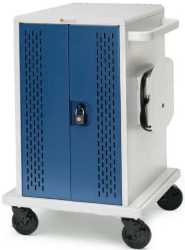
White and blue medical device with perforated panels, displayed on a wheeled cart (no visible text or symbols)TECHNICAL SPECIFICATIONS
CAPACIT Y
36 Devices
COMPATIBILITY
Designed for various sized Chromebooks, yet versatile enough to support most tablets, laptops/hybrids and ultrabooks. Uses device manufacturer supplied AC power cord.
UNIT DIMENSIONS
25.25"W x 26.5"D x 41.3875"H
SLOT DIMENSIONS
1.25"W x 14.75"D x 9.875"H
WEIGHT WITHOUT DEVICES
142 lbs.
WARRANTY
For product specific warranty information, please visit bretford.com/warranty
TIMER
Digital
SHIPPING
Ships fully assembled
IMPORTANT USER NOTES
• Product is for indoor use only.
- User can plug in 36 devices at one time.
- Turn power switch off before plugging in devices.
- Turn power switch off before unplugging the cart.
- Do not plug the cart in if the switch or power cord has been damaged.
- Do not plug the power cord into another extension cord or re-locatable power tap.
- Be sure to turn power switch off and unplug cart before moving to a different location.
- Ensure casters are locked before opening cart doors.
- Be sure to lock up cart in a secure environment after every use.
- Do not share the lock combination code with any unauthorized persons.
- The socket-outlet shall be installed near the equipment and shall be easily accessible.
USER GUIDE | CORE™ 36M CART
natural_image
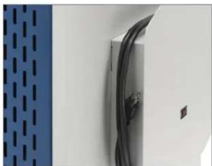
Close-up of a white wall panel with black cables and a blue perforated panel on the left (no text or symbols visible)Cord Winder and Power Switch
natural_image
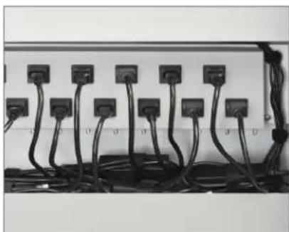
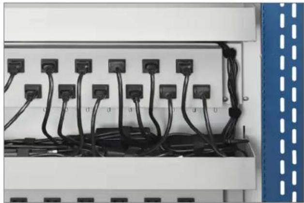
Electrical wiring and connectors in a rack (no visible text or symbols)AC Outlet Access – Adapter Storage
natural_image
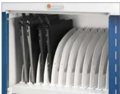
Interior view of a white industrial storage unit with multiple curved white panels and black components, no visible text or symbols.Device Storage
GENERAL USE
POWER SWITCH
Located on the right hand side of the cabinet.
AC OUTLET ACCESS - ADAPTER STORAGE
Bins provide convenient adapter storage. Plug adapters into AC outlets as needed. Use VELCRO® straps to secure power adapters.
DEVICE STORAGE
Polypropylene dividers store devices vertically and offer optimal spacing for device compatibility.

natural_image
Close-up of a blue metal door with a black knob and dashed vertical lines (no text or symbols visible)Using the Handle
natural_image
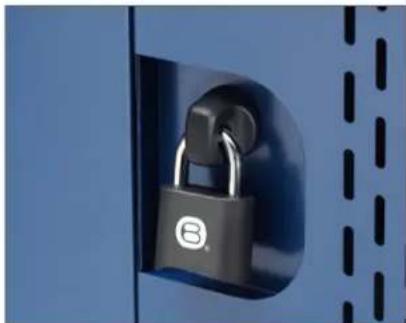
Close-up of a black padlock securing a blue metal sheet with dashed lines (no text or symbols visible)Inserting The Shackle / Lock Programming
natural_image
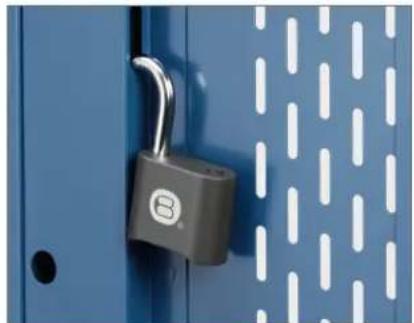
Close-up of a blue metal cabinet with a black padlock securing its door (no text or symbols visible)Interior Door Lock Holder
TORQUE RESISTANT HANDLE & LOCK INSTRUCTIONS
USING THE HANDLE
The torque resistant handle/lock serves as a handle to open and close the cabinet when the shackle is not inserted.
INSERTING THE SHACKLE
Hold the lock shackle on a slight angle when inserting into the shackle opening and push firmly. Once the shackle is inserted the cam is no longer engaged and the torque resistant handle/lock will spin which deters access to devices by lowering the risk of the cam breaking.
LOCK PROGRAMMING
To program the user programmable combination padlock included:
- Open the padlock using combination "0000."
- Insert the programming key and turn 90 degrees.
- Set the combination you would like to use.
- Remove the programming key.
USER GUIDE | CORE™ 36M CART
DEVICE STORAGE & CABLE MANAGEMENT
- Starting in the rear of the cart, insert a power adapter in the storage bin for the associated device storage shelf (top, middle or bottom).
- Measure the amount of cable necessary to reach from the power adapter located in the bin to the front of the cart, (around the AC outlet box, through the divider panel and through the cable management hooks). Leave sufficient slack for the power connector to connect to the device.
- Wrap remaining cable to the power adapter using one of the VELCRO® straps that came with the cart.
- Plug the AC cord into one of the outlets nearest to where the brick is located in the bin.
- Repeat the above process for the 36 device's power adapters and cables.
- Insert a device into each of the 36 device slots.
- Plug the power connector into each of the 36 devices.
- Place cart near a wall outlet and plug cart in.
- Turn on the power switch (on the cord-winder side of the cart).
- Once the timer is turned on, it begins rotating power to the different power strips every three (3) minutes. This allows for efficient charging of the devices in the cart from one 15 amp wall circuit.
- Only one group of the total devices in the cart will be charging at a time-rotating every three minutes.
- Supplied numbered stickers can be applied to shelves in front of dividers, for slot numbering, if desired.
natural_image
Electrical cabinet with multiple black cables and terminal blocks, no visible text or symbols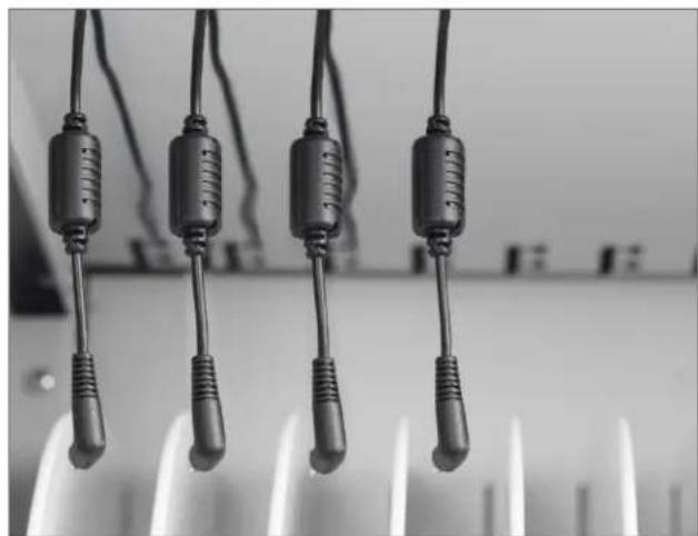
natural_image
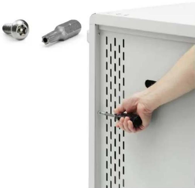
Close-up of four black plastic clips hanging from a surface, no text or symbols visibleREMOVING REAR ACCESS PANEL (CORE36MSBP-CTTZ)
Using the included T2511 Torx bit, remove the four screws securing the rear adapter access panel. Use the handle cutout to remove the panel. Inside, plug adapters into AC outlets as needed, and secure with velcro straps. Reattach rear adapter access panel using T2511 Torx bit and included security screws. Tools required: Multi-Bit screwdriver, T2511 Torx bit (included)
- Insert the T2511 Torx bit into your Multi-Bit screwdriver.
- Remove the four security screws from the back adapter access panel.
- Remove the rear adapter access panel.
- Install your power adapters as needed.
- Replace the rear adapter access panel.
- Replace the four security screws, securing the rear adapter access panel, using the included TORX 2511 bit.
Part #031-10065 · V6 07.2016
Bretford, B design, and Core are trademarks or registered marks of Bretford Manufacturing, Inc. Patents Pending. ©2015 Bretford Manufacturing, Inc. All rights reserved. All other referenced product names and logos are trademarks of their respective owners.