
EC45U3032 - Cabinet / Rack Black Box - Free user manual and instructions
Find the device manual for free EC45U3032 Black Box in PDF.

| Product Type | Server Rack Cabinet |
| Brand | Black Box |
| Model | EC45U3032 |
| Form Factor | 19-inch rack |
| Rack Height | 45U (78.75 in / 2000 mm) |
| External Dimensions (W x D x H) | 600 mm x 1000 mm x 2000 mm (23.6 x 39.4 x 78.7 in) |
| Weight (Empty) | 120 kg (265 lbs) |
| Material | Steel, powder-coated finish |
| Color | Black |
| Door Type | Perforated front and rear doors with lock |
| Side Panels | Removable locking side panels |
| Maximum Static Load | 800 kg (1764 lbs) |
| Mounting Rails | Adjustable depth mounting rails, EIA-310 compliant |
| Ventilation | Perforated doors for front-to-rear airflow |
| Cable Management | Built-in cable entry openings and management accessories |
| Security | Lockable doors and side panels |
| Grounding | Integrated grounding point; grounding kit included |
| Operating Temperature | 0°C to 50°C (32°F to 122°F) |
| Standards Compliance | EIA-310-D, RoHS |
| Included Accessories | Mounting screws, cage nuts, keys, grounding kit |
Frequently Asked Questions - EC45U3032 Black Box
User questions about EC45U3032 Black Box
0 question about this device. Answer the ones you know or ask your own.
Ask a new question about this device
Download the instructions for your Cabinet / Rack in PDF format for free! Find your manual EC45U3032 - Black Box and take your electronic device back in hand. On this page are published all the documents necessary for the use of your device. EC45U3032 by Black Box.
USER MANUAL EC45U3032 Black Box
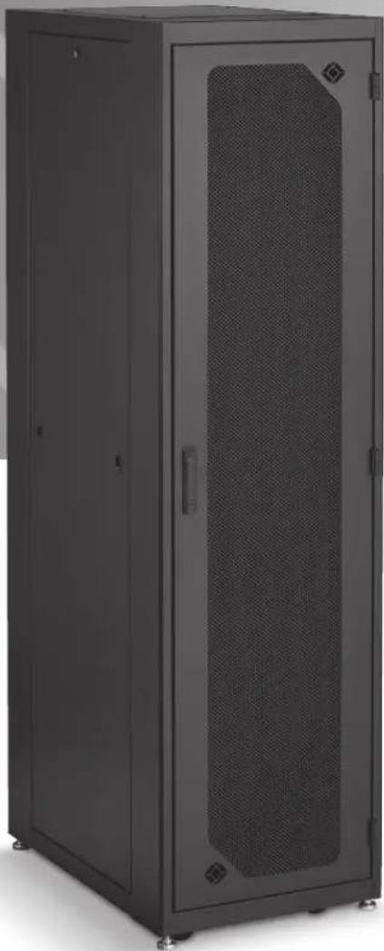
Elite™ Cabinet/Rack User's Manual
Fully assembled, ready-to-use custom cabinets.
You chose your options, then we built the cabinet you need.
Trademarks Used in this Manual
Black Box and the Double Diamond logo are registered trademarks, and Elite is a trademark, of BB Technologies, Inc.
VELCRO is a registered trademark of Velcro Industries B.V.
Any other trademarks mentioned in this manual are acknowledged to be the property of the trademark owners.
We're here to help! If you have any questions about your application or our products, contact Black Box Tech Support at 724-746-5500 or go to blackbox.com and click on "Talk to Black Box."
You'll be live with one of our technical experts in less than 60 seconds.
Preface 4
Safety Symbols Used in this Manual 4
Safety Considerations 4
Installation....5
Receiving, Unpacking, and Removing the Elite Cabinet/Rack from the Pallet 5
Service 5
-
Specifications....6
-
Overview 11
2.1 Introduction 11
2.2 Features 11
2.3 What's Included 11
2.4 Part Number Description/Cabinet Components....11
2.5 Optional Accessories 17
2.6 Elite Cabinet with Optional Accessories....19
- Changing the Cabinet's Configuration 20
3.1 Casters and Leveling Legs 20
3.2 Door Handle Operation....21
3.3 Removing or Changing the Doors 21
3.3.1 Removing or Installing a Door....21
3.3.2 Reversing a Door 22
3.4 Removing or Installing a Side Panel 23
3.5 Top Panel and Mounting Options 24
3.6 Adjusting the Rails 25
3.7 Bottom Panel 25
3.8 Power Strip Mounting 26
3.9 Baying Kit....27
Preface
This manual is provided to prevent service personnel from committing an act that results in the risk of fire, electric shock, or injury to persons. Only trained service personnel should receive, unpack, and assemble the Elite Cabinet/Rack. In addition, only trained service personnel should install equipment in the rack.
Safety Symbols Used in This Manual
This manual provides general safety guidelines to be observed during installation, operation, and maintenance of the Elite Cabinet/Rack.

WARNING: Failure to follow directions in the warning could result in injury to persons or loss of life.

CAUTION: Failure to follow directions in the caution could result in damage to equipment or storage data.
Safety Considerations

WARNING: Improper handling and use of the Elite Cabinet/Rack could result in equipment damage, serious injury, or possible death.
Only trained service personnel should be used to remove the Elite Cabinet/Rack from the carton. Also be sure you have a sufficient number of service personnel. Do not attempt to move the Elite Cabinet/Rack by yourself.
Only UL ® Listed ITE (Information Technology Equipment) units should be installed in the Elite Cabinet/Rack.
Be sure to read and follow all individual manufacturer equipment manuals for safety and installation instructions.
Proper spacing is required when installing electrical equipment to avoid electrical shock. Maintain minimum spacing between the accessories and components and the Ultra Wallmount Rack for safe operation of the equipment when installed in accordance with the National Electric Code ANSI/NFPA 70-1999.
The ambient temperature operating range for the Elite Cabinet/Rack and accessories is +50 to +95° F (+10 to +35° C). The non-operating temperature is -4 to +140° F (-20 to +60° C).
Installation
Receiving, Unpacking, and Removing the Elite Cabinet/Rack from the Pallet
Inspect for damage and report damage if there is damage before receiving. Unpack the rack by carefully removing the corrugated carton and corners. Avoid damaging the enclosure when removing packaging.

WARNING: Only trained service personnel should be used to remove the rack from the carton. Also be sure you have a sufficient number of service personnel. Do not attempt to move Elite Cabinet/Racks by yourself.

WARNING: Be careful when moving racks before installation. Sudden stops and starts, excessive force, obstructed routes, and uneven floor surfaces may cause the rack to topple over.

WARNING: Only install equipment after the Elite Cabinet/Rack has been properly secured. Do not move the Elite Cabinet/Rack assembly while loaded.
Once in place at the desired/intended location, deploy the leveling feet for maximum stability.
Rated or maximum load capacity for the Elite Cabinet/Rack is 2000 pounds on the floor on leveling glides.
To maintain a uniform distribution of the mechanical load in the Elite Cabinet/Rack, load the heaviest equipment first at the bottom of the Elite Cabinet/Rack and load the lighter units at the top.
Service
The Elite Cabinet/Rack should only be repaired by personnel trained by Black Box, or returned to Black Box for repair. Contact Black Box Technical Support at 724-746-5500 or go to blackbox.com and click on "Talk to Black Box."
1. Specifications
Table 1-1 lists specifications for the cabinet shown in Figures 1-1 through 1-4.
Table 1-1. Cabinet specifications.
| Frame Part Number Prefix | Height | Overall Height* | Width | Depth | RU | Rail (Min.-Max.) Depth | Side Panel Height | Side Panel Depth | Rear Bottom Cable Access Hole | Top Corner Knockouts |
| EC24U3032 | 48" | 49.974" | 30" | 32" | 24 | 6"-30" | 43.657" | 19.116" | 14.5" x 4" | included |
| EC24U2442 | 48" | 49.974" | 24" | 42" | 24 | 6"-34.5" | 43.657" | 29.116" | 16.5" x 5.25" | not included |
| EC38U2432 | 72" | 73.974" | 24" | 32" | 38 | 6"-30" | 67.657" | 19.116" | 8.5" x 4" | not included |
| EC38U2436 | 72" | 73.974" | 24" | 36" | 38 | 6"-34" | 67.657" | 23.116" | 16.5" x 4.25" | not included |
| EC38U3032 | 72" | 73.974" | 30" | 32" | 38 | 6"-30" | 67.657" | 19.116" | 14.5" x 4" | included |
| EC38U3036 | 72" | 73.974" | 30" | 36" | 38 | 6"-34" | 67.657" | 19.116" | 22.5" x 5.25" | not included |
| EC42U2442 | 79" | 80.974" | 24" | 42" | 42 | 6"-34.5" | 73.657" | 29.116" | 18.5" x 5.25" | not included |
| EC42U3042 | 79" | 80.974" | 30" | 42" | 42 | 6"-34.5" | 73.657" | 29.116" | 22.5" x 5.25" | included |
| EC45U2436 | 84" | 85.974" | 24" | 36" | 45 | 6"-34" | 79.657" | 23.116" | 8.5" x 4" | not included |
| EC45U3032 | 84" | 85.974" | 30" | 32" | 45 | 6"-30" | 79.657" | 19.116" | 14.5" x 4" | included |
| EC45U3036 | 84" | 85.974" | 30" | 36" | 45 | 6"-34" | 79.657" | 23.116" | 14.5 x 4" | included |
| EC45U2442 | 84" | 85.974" | 24" | 42" | 45 | 6"-34.5" | 79.657" | 29.116" | 18.5" x 5.25" | not included |
| EC45U3042 | 84" | 85.974" | 30" | 42" | 45 | 6"-29" | 79.657" | 29.116" | 22.5" x 5.25" | included |
| EC45U3048 | 84" | 85.974" | 30" | 48" | 45 | 6"-29" | 79.657" | 29.116" | 22.5" x 5.25" | included |
*Height with casters.

Figure 1-1. Front view (doors removed for clarity).

Figure 1-2. Cabinet shown with side panel.

Figure 1-3. Top view, 30" wide cabinet.

Figure 1-4. Bottom view, 30" cabinet.
2. Overview
2.1 Introduction
The Elite Cabinet is a fully assembled, ready-to-use cabinet that's customized to your specifications. It ships completely assembled with its front and rear doors unlocked, with two keys and this user's manual.
2.2 Features
Your custom cabinet features your choice of top panels, rail type, front door type, rear door type, side panel, top panel, anti-tip, and lock type. The components of the cabinet you received are the ones you ordered.
The top panel is either solid, vented, 1-fan, 2-fan, 3-fan, 6-fan, or no top panel.
The front and rear doors are split fan, plexi, solid, split high flow mesh, or high flow mesh.
The side panels are either solid or vented.
The cabinets are available in four overall heights, and 10 overall frame sizes. See Table 2-1.
2.3 What's Included
Your package should include the following items. If anything is missing or damaged, please contact Black Box Technical Support at 724-746-5500.
- Cabinet with square hole rails OR
- Cabinet with tapped rails
• (50) cage nuts and (50) screws • (50) 10-32 screws
• (4) pairs of keys • (4) pairs of keys - 60" of grommet material
- 60" of grommet material
- Earthing Kit: • This user's manual
(6) grounding straps, 2-ft. long,
12 AWG, 12-10 ring on each end,
and a spade quick disconnect in the middle plus hardware
- This user's manual
2.4 Part Number Description/Cabinet Components
The part number on your package corresponds to the options you chose when ordering your cabinet (See Figure 2-1 and Tables 2-1 through 2-7). The first 9 characters in the product code represent the cabinet's size. The 10th character describes the rail type (square or 10-32 tapped rails). The 11th and 12th characters describe the front and rear doors. The 13th character represents the side panel. The 14th character describes the top. The 15th character tells you whether or not the cabinet is anti-tip or not. The 16th character describes the lock type (keyed, combination, or none).
Figures 2-2 through 2-6 illustrate the custom possibilities for your cabinet. Tables 2-1 through 2-7 list these options.
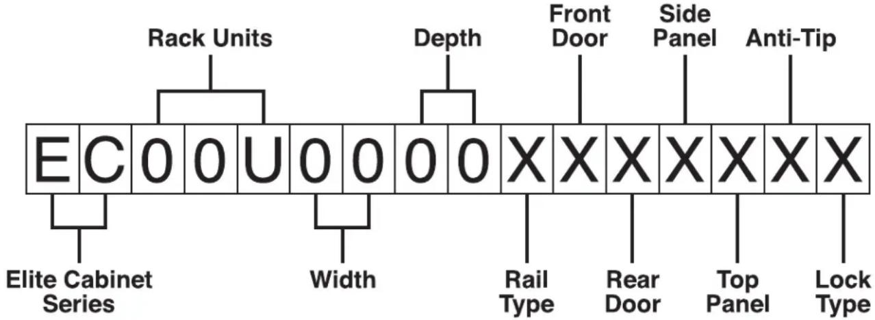
Figure 2-1. Elite Cabinet part number system.
Table 2-1. Elite Cabinet Size Options
| EC24U3032 | 24U (48"H x 30"W x 32"D) |
| EC24U2442 | 24U (48"H x 24"W x 42"D) |
| EC38U2432 | 38U (72"H x 24"W x 32"D) |
| EC38U2436 | 38U (72"H x 24"W x 36"D) |
| EC38U3032 | 38U (72"H x 30"W x 32"D) |
| EC38U3036 | 38U (72"H x 30"W x 36"D) |
| EC42U2442 | 42U (79"H x 24"W x 42"D) |
| EC42U3042 | 42U (79"H x 30"W x 42"D) |
| EC45U2436 | 45U (84"H x 24"W x 36"D) |
| EC45U3032 | 45U (84"H x 30"W x 32"D) |
| EC45U3036 | 45U (84"H x 30"W x 36"D) |
| EC45U2442 | 45U (84"H x 24"W x 42"D) |
| EC45U3042 | 45U (84"H x 30"W x 42"D) |
| EC45U3048 | 45U (84"H x 30"W x 48"D) |
Table 2-2. Rail type options.
| Rail Type | |
| S | square rails |
| T | 10-32 tapped rails |
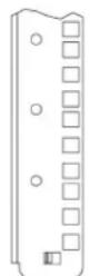
Square rail
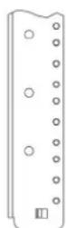
Tapped rail
Figure 2-2. Rail type options: square or tapped.
Table 2-3. Front Door or Rear Door.
| N | None |
| F | Fan Door |
| P | Plexi |
| S | Solid |
| D | Split Mesh |
| M | Mesh |
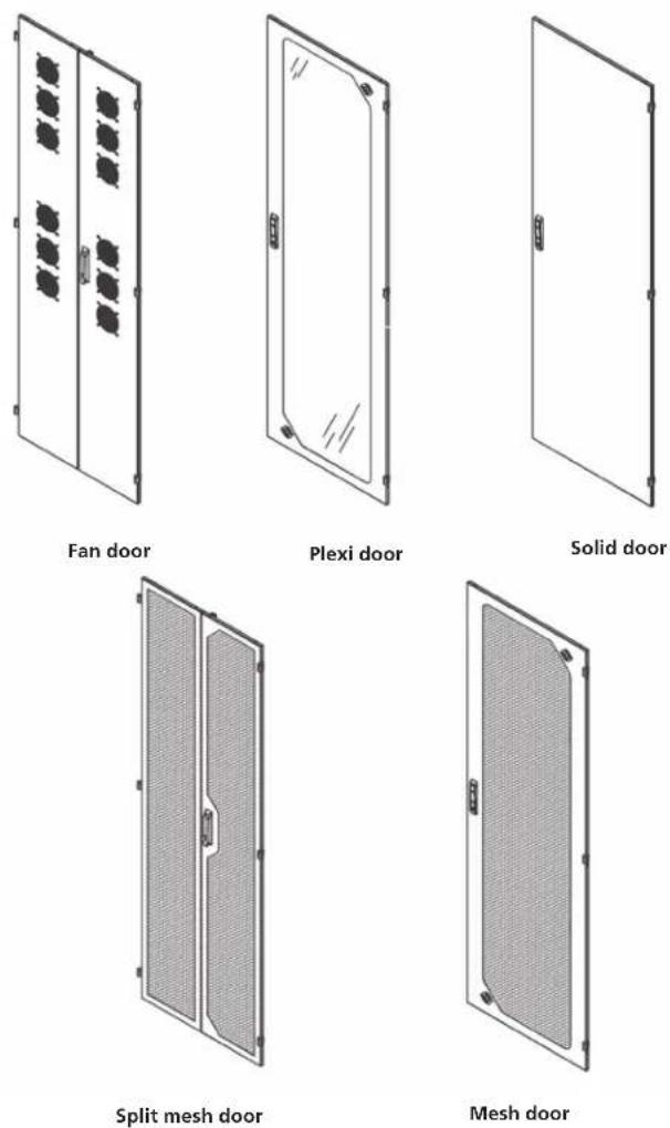
Figure 2-3. Door options.
Table 2-4. Side Panel options.
| N | None |
| S | Solid |
| M | Vented |
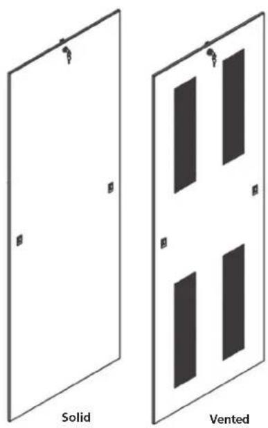
Figure 2-4. Side Panel options.
Table 2-5. Top options.
| N | None |
| S | Solid |
| M | Vented |
| C | Chimney top |
| 1 | 1-fan unit (10" fan, 550 CFM) |
| 2 | 2-fan unit (10" fans, 1100 CFM) |
| 3 | 3-fan unit (4" fans, 225 CFM) |
| 6 | 6-fan unit (4" fans, 450 CFM) |
*220-V versions available.
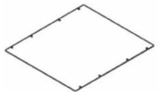
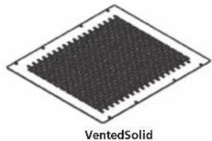

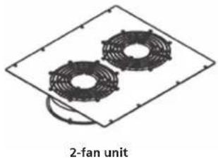
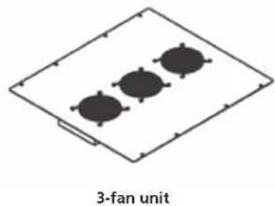
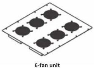
Figure 2-5. Top panel options.
Table 2-6. Anti-Tip.
| Y | Yes | |
| N | No |

Figure 2-6. Anti-tip legs installed on bottom of cabinet.
Table 2-7. Lock Type.
| K | Keyed |
| C | Combination |
| N | None |
| B | Biometric |
2.5 Optional Accessories
This section lists optional accessories not included in the cabinet's base part number. (These optional accessories must be ordered separately, and are not discussed in detail in this manual, since they have their own manual that ships with the accessory.)
Optional handles:
• RM624 (padlock with key)
• RM626 (padlock) handle
Horizontal cable management:
- ECFB32 (front to back cable management for 30"W x 32"D cabinets)
- ECFB36 (front to back cable management for 30"W x 36"D cabinets)
- ECFB42 (front to back cable management for 30"W x 42"D cabinets)
- ECFB48 (front to back cable management for 30"W x 48"D cabinets)
• ECHLB32 (horizontal lacing bar for 32 "D cabinets)
• ECHLB36 (horizontal lacing bar for 36"D cabinets) - ECHLB42 (horizontal lacing bar for 42 "D cabinets)
- ECHLB48 (horizontal lacing bar for 48"D cabinets)
Vertical Cable Management:
• ECVLB48 (vertical lacing bar, 48")
• ECVLB72 (vertical lacing bar, 72")
• ECVLB79 (vertical lacing bar, 79")
• ECVLB84 (vertical lacing bar, 84")
ECVCM Vertical Cable Management (19.25" segments)
- 2 lengths for 48"H
• 3 lengths for 72"H and 79"H - 4 lengths for 84"H
Additional rails
Extra set of rails, M6
• EC48M6 (extra pair of M6 rails for 48"H cabinet)
• EC72M6 (extra pair of M6 rails for 72"H cabinet)
• EC79M6 (extra pair of M6 rails for 79"H cabinet)
• EC84M6 (extra pair of M6 rails for 84"H cabinet)
Extra sets of rails, 10-32
• EC48T (extra pair of tapped rails for 48"H cabinet)
• EC72T (extra pair of tapped rails for 72"H cabinet)
• EC79T (extra pair of tapped rails for 79"H cabinet)
• EC84T (extra pair of tapped rails for 84"H cabinet)
23" Mounting Kit for 30" wide cabinets
• EC23MK32 (23" mounting kit for 30"W x 32"D cabinet)
• EC23MK36 (23" mounting kit for 30"W x 36"D cabinet)
• EC23MK42 (23" mounting kit for 30"W x 42"D cabinet)
• EC23MK48 (23" mounting kit for 30"W x 48"D cabinet)
Bottom Panels and Filter Kits
Solid Bottom Panel
• ECBSKL2436 (solid bottom for 24"W x 36"D BB EC cabinet)
• ECBSKL2442 (solid bottom for 24"W x 42"D BB EC cabinet)
• ECBSKL3032 (solid bottom for 30"W x 32"D BB EC cabinet)
• ECBSKL3036 (solid bottom for 30"W x 36"D BB EC cabinet)
• ECBSKL3042 (solid bottom for 30"W x 42"D BB EC cabinet)
• ECBSKL3048 (solid bottom for 30"W x 48"D BB EC cabinet)
Solid Rear Bottom Panel
• ECBSKS24 (solid rear bottom for 24"W BB EC cabinet)
• ECBSKS30 (solid rear bottom for 30"W BB EC cabinet)
Filter Kit Bottom
• ECBFKL2436 (filter kit bottom for 24"W x 36"D BB EC cabinet)
• ECBFKL2442 (filter kit bottom for 24"W x 42"D BB EC cabinet)
• ECBFKL3032 (filter kit bottom for 30"W x 32"D BB EC cabinet)
• ECBFKL3036 (filter kit bottom for 30"W x 36"D BB EC cabinet)
• ECBFKL3042 (filter kit bottom for 30"W x 42"D BB EC cabinet)
Brush Rear Grommet Kit for small opening in the bottom
• ECBBGKS24 (brush rear grommet kit for 24"W BB EC cabinet)
• ECBBGKS30 (brush rear grommet kit for 30"W BB EC cabinet)
Brush Rear Grommet Kit for large opening in the bottom
• ECBGKL2436 (brush rear grommet kit for 24"W x 36"D cabinet)
• ECBGKL2442 (brush rear grommet kit for 24"W x 42"D cabinet)
• ECBGKL3032 (brush rear grommet kit for 30"W x 32"D cabinet)
• ECBGKL3036 (brush rear grommet kit for 30"W x 36"D cabinet)
• ECBGKL3042 (brush rear grommet kit for 30"W x 42"D cabinet)
Top Panel Options
Chimney and Chimney Fan (also available in 220 V)
- ECTOPCHIM (chimney for small opening with solid top for large opening)
• ECTOPCHIMFT (fan tray for ECTOPCHIM)
Cable Trough
• EC24WTCTK (top cable trough kit, 24" wide)
• EC30WTCTK (top cable trough kit, 30" wide)
• ECP3U (panel with circular knockouts for 3U opening)
Cable Management—Brush Grommet Kit
• ECBGK3U (brush grommet kit for 3U opening)
Waterfall Brackets for 3U top opening
• ECW3U (waterfall for top 3U [with cable pass through])
Ladder Rack Mounting Brackets
• EC24LR (24"W ladder rack bracket)
Misc.
- ECLK (light kit)
• ECPDUMK (vertical PDU 19" mounting kit, 0 RMU)
• ECAT1 (anti-tip legs)
• ECNH (networking hardware)
Air Dams
• ECAD24 (for 24" wide cabinets only)
• ECAD30 (for 30" wide cabinets only)
Air Funnel Kits
• ECAIRFLOW42 (for 24"W x 42"D and 30"W x 42"D)
• ECAIRFLOW3042FT (for 30"W x 42"D)
• ECAIRFLOW36 (for 24"W x 36"D)
• ECAIRFLOW2436FT (for 24"W x 36"D)
• ECAIRFLOW2442FT (for 24"W x 42"D)
Brush Grommet Top Panel
ECTOP8 (for 12U opening)
Vertical Jack Panels
- ECJACKPANEL46 (46") (for 30" wide cabinets only)
- ECJACKPANEL92 (92") (for 30" wide cabinets only)
PDU Mounting Brackets
• ECPDUMK24
• ECPDUMK30
2.6 Elite Cabinet with Optional Accessories
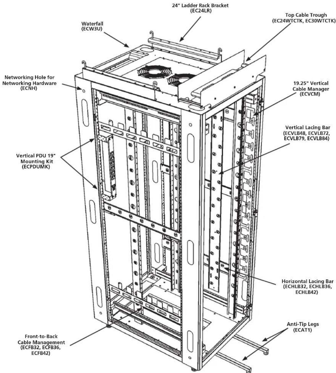
Figure 2-7. The Elite Cabinet with optional accessories.
3. Changing the Cabinet's Configuration
3.1 Casters and Leveling Legs
CAUTION: To install casters or levelers, you must tip the enclosure onto its side. The enclosure is very heavy, so you may need several people to lay it on its side. Do not lay the enclosure on its front or back. This may damage the door and hinges.
HINT: Removing the doors and side panels before tipping will help reduce the enclosure's weight and help prevent damage to the side panel locks.

Figure 3-1. Casters and levelers.
Caster Mounting:
- Tip the enclosure and lay it onto its side.
- Place a caster assembly over the four threaded studs located in one of the recessed areas in the bottom of the enclosure.
- Thread one 5/16 -18 hex nut onto each of the four studs and tighten with a 1/2 " socket or nut driver.
- Repeat Steps 2 and 3 for the three remaining casters.
Adjustable Leveler Mounting:
- Tip the enclosure and lay it onto its side.
- Place a leveling leg into one of the four 1/2 "-13 threaded holes found at the corners of the enclosure.
- Using a 3/4 " open-end wrench, tighten the levelers to the desired position.
- Repeat Steps 2 and 3 for the remaining levelers.
3.2 Door Handle Operation
The Elite enclosure ships with its front and rear doors unlocked, and includes two keys.
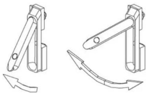
Figure 3-2. Door handle drawings.
3.3 Removing or Changing the Doors
3.3.1 Removing or Installing a Door
Open the door beyond 90°, then grasp the door with both hands and carefully lift it upward. When the door is free of all three hinge pins, pull the door away from the enclosure. To attach the door, align all three door hinges to their respective hinge pins on the enclosure and slowly slide the door down until seated.
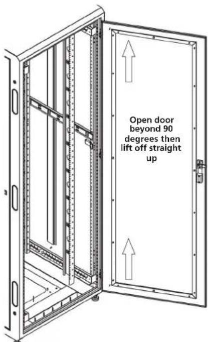
Figure 3-3. Removing or installing a door.
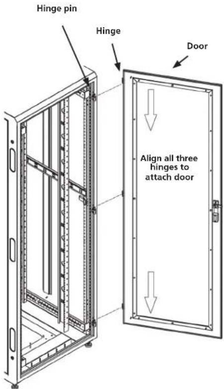
Figure 3-4. Attaching a door.
3.3.2 Reversing a Door
The front and rear doors are installed with a right-hand hinge as standard from Black Box. Removing the hinges enables you to reverse the door by flipping them over and reinstalling the hinges using the universal mounting holes. All the enclosure frames and doors can be hinged right- or left-hand. The handle can be reversed along with the hinging. See Figure 3-5.
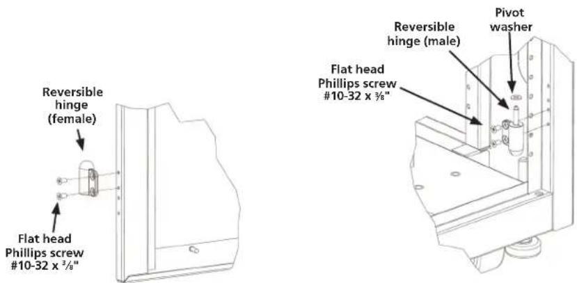
Figure 3-5. Reversing a door.
3.4 Removing or Installing a Side Panel
The side panels connect to the enclosure frame with two quick-release latches and a keyed lock. To remove the side panel, unlock the panel and press the quick-release latches down and release them. Then tilt the top of the side panel out slightly and lift the side panel up a couple of inches until it is free. To install the side panel, reverse the process. Make sure the slots on the side panel engage with the two tabs at the bottom of the frame.

Figure 3-6. Removing or installing a side panel (30" wide cabinet shown).
3.5 Top Panel and Mounting Options
The top panel of the enclosure is installed at Black Box. To remove the top panel, remove the four #10-32 x 1" large Phillips pan-head screws. Then simply lift the top panel up and off. There are six versions of top panels (solid, perforated, 1-fan, 2-fan, 3-fan, 6-fan).
The top panel provides 12U of standard rackmount space that you can customize. When one of the standard top panels is not used, you can use this area to mount patch panels, additional cable management, PDUs, 19" fan panels, and other lightweight items.
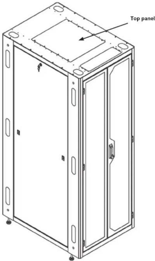
Figure 3-7. Top panel mounting (30" wide cabinet shown).
3.6 Adjusting the Rails
Mounting Rails
The vertical mounting rails are installed with all standard frames. You can configure the 30" wide enclosure to 23" EIA mounting with an optional bracket set. Extra sets of both square hole rails (M6) and tapped #10-32 rails are available as accessories. (See page 15).
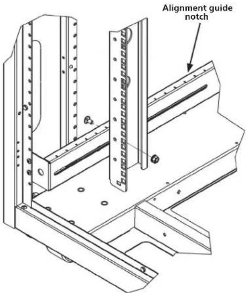
Figure 3-8. Adjusting the vertical mounting rails.
Rails are attached using a sliding nut and ¼-20 hex head bolt. Loosen both top and bottom bolts, using a ¾" socket set, then adjust the rails front to back using the alignment guide notches shown in Figure 3-8. Rackmount units (RU) are marked on rails for easy equipment mounting. Round cable passthrough and vertical and horizontal cable tie-down slots are provided on side of rails.
3.7 Bottom Panel
Figure 3-9 shows the cabinet's bottom panel.
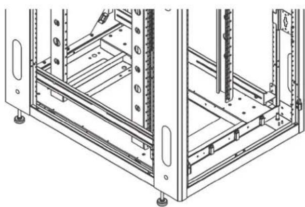
Figure 3-9. Bottom panel.
3.8 Power Strip Mounting
These universal power strip brackets enable you to mount a power distribution unit (PDU) with button mounting as shown in Figure 3-10.
- Measure the required mounting distance top to bottom.
- Install the brackets.
- Install the power strip.

Figure 3-10. Mounting a power strip.
3.9 Baying Kit
Use the kit components shown in Figure 3-11 to link two cabinets together.

Figure 3-11. Baying kit components.
Protective Grounding
Protective grounding studs are provided along with grounding jumper wires that electrically bond the Elite Cabinet doors to one of the Elite Cabinet sides.

WARNING: To avoid injury to persons or loss of life, ground each Elite Cabinet individually to the dedicated branch circuit ground.
Connecting Main Protective Grounding Stud to the Dedicated Branch Circuit Earthing Ground
Connect the dedicated branch circuit ground conductor to the main protective grounding stud located inside at the bottom rear of the Elite Cabinet frame using a listed ring or closed-loop terminal.
Connecting Main Protective Grounding Stud to the Protective Bonding Conductors
Connect the rear doors to the main protective grounding studs located inside at the bottom and top rear of the enclosure chassis using a listed ring or closed-loop terminal. Connect the front door to the grounding stud located inside at the bottom front of the Elite Cabinet frame using a listed ring or closed-loop terminal.
Parts Not Bonded to Protective Earthing Terminal
The following parts are not effectively bonded to the protective earthing terminal: rails and front to back rail horizontals. If these parts need to be bonded to the protective earthing terminal, do so in accordance with Article 250 or the National Electric Code.
Black Box Tech Support: FREE! Live. 24/7.
Tech support the way it should be.

Great tech support is just 60 seconds away at 877-877-2269 or blackbox.com.

BLACK BOX®
About Black Box
Black Box Network Services is your source for an extensive range of networking and infrastructure products. You'll find everything from cabinets and racks and power and surge protection products to media converters and Ethernet switches all supported by free, live 24/7 Tech support available in 60 seconds or less.
© Copyright 2016. All rights reserved.
EC24U3032, rev. 2
- FULLY ASSEMBLED, READY-TO-USE CUSTOM CABINETS
- TRADEMARKS USED IN THIS MANUAL
- PREFACE
- SAFETY SYMBOLS USED IN THIS MANUAL
- SAFETY CONSIDERATIONS
- INSTALLATION
- SERVICE
- SPECIFICATIONS
- OVERVIEW
- 2.1 INTRODUCTION
- 2.2 FEATURES
- 2.3 WHAT'S INCLUDED
- 2.4 PART NUMBER DESCRIPTION/CABINET COMPONENTS
- 2.5 OPTIONAL ACCESSORIES
- OPTIONAL HANDLES
- HORIZONTAL CABLE MANAGEMENT
- VERTICAL CABLE MANAGEMENT
- ECVCM VERTICAL CABLE MANAGEMENT (19.25" SEGMENTS)
- ADDITIONAL RAILS
- EXTRA SET OF RAILS, M6
- EXTRA SETS OF RAILS, 10-32
- 23" MOUNTING KIT FOR 30" WIDE CABINETS
- BOTTOM PANELS AND FILTER KITS
- SOLID BOTTOM PANEL
- SOLID REAR BOTTOM PANEL
- FILTER KIT BOTTOM
- BRUSH REAR GROMMET KIT FOR SMALL OPENING IN THE BOTTOM
- BRUSH REAR GROMMET KIT FOR LARGE OPENING IN THE BOTTOM
- TOP PANEL OPTIONS
- CHIMNEY AND CHIMNEY FAN (ALSO AVAILABLE IN 220 V)
- CABLE TROUGH
- CABLE MANAGEMENT—BRUSH GROMMET KIT
- 2.6 ELITE CABINET WITH OPTIONAL ACCESSORIES
- CHANGING THE CABINET'S CONFIGURATION
- 3.1 CASTERS AND LEVELING LEGS
- CASTER MOUNTING
- ADJUSTABLE LEVELER MOUNTING
- 3.2 DOOR HANDLE OPERATION
- 3.3 REMOVING OR CHANGING THE DOORS
- 3.3.1 REMOVING OR INSTALLING A DOOR
- 3.3.2 REVERSING A DOOR
- 3.4 REMOVING OR INSTALLING A SIDE PANEL
- 3.5 TOP PANEL AND MOUNTING OPTIONS
- 3.6 ADJUSTING THE RAILS
- 3.7 BOTTOM PANEL
- 3.8 POWER STRIP MOUNTING
- 3.9 BAYING KIT
- PROTECTIVE GROUNDING
- BLACK BOX TECH SUPPORT: FREE! LIVE. 24/7
- BLACK BOX®
- ABOUT BLACK BOX
Brand : Black Box
Model : EC45U3032
Category : Cabinet / Rack