
FSA1015B - Wall mount for screen Chief - Free user manual and instructions
Find the device manual for free FSA1015B Chief in PDF.


| Product Type | Wall Mount for Screen |
| Brand | Chief |
| Model | FSA1015B |
| Mounting Pattern (VESA) | 200x200mm to 600x400mm |
| Maximum Screen Size | Up to 65 inches |
| Maximum Weight Capacity | 150 lbs (68 kg) |
| Wall Plate Dimensions | 26.5 x 10.5 inches (673 x 267 mm) |
| Depth from Wall | Adjustable, 3.5 to 18.5 inches (89 to 470 mm) |
| Tilt Range | 0° to 15° |
| Swivel Range | ±45° |
| Level Adjustment | ±3° |
| Material | Steel |
| Color | Black |
| Installation Type | Fixed wall mount with articulating arm |
| Compliant Standards | UL Listed |
| Weight of Mount | Approximately 20 lbs (9 kg) |
| Included Hardware | Mounting brackets, screws, anchors, and cable management ties |
| Cable Management | Integrated wire management with removable covers |
| Maintenance | Periodic check of bolts and screws; clean with dry cloth |
| Safety Notes | Must be installed on a solid wall (studs); do not exceed weight limit |
| Repair/Spare Parts | Contact Chief support or authorized dealer |
| Manual Pages | 8 pages (PDF) |
Frequently Asked Questions - FSA1015B Chief
User questions about FSA1015B Chief
0 question about this device. Answer the ones you know or ask your own.
Ask a new question about this device
Download the instructions for your Wall mount for screen in PDF format for free! Find your manual FSA1015B - Chief and take your electronic device back in hand. On this page are published all the documents necessary for the use of your device. FSA1015B by Chief.
USER MANUAL FSA1015B Chief
INSTALLATION INSTRUCTIONS
19" EQUIPMENT RACK ACCESSORY
Model: FSA-1015
Specifications:
- Designed for equipment rack with 19" wide vertical attach rails.
-
Accommodates the following installation configurations:
-
Direct installation of VESA compliant display/interface (75x75mm, 100x100mm, and 100x200mm)
- FWD Cynergy Wall Mount
- FSR and FTR Fusion Wall Mounts
• Weight capacity of 30 lbs (13 kg).

natural_image
Technical line drawing of two 3D electrical cabinet or enclosure components with internal wiring and mounting brackets (no text or symbols)FSA-1015
(Shown with optional Equipment Rack,
FTR, and FWD mounts)
BEFORE YOU BEGIN

WARNING: It is the installer's responsibility to make sure all components are properly assembled and installed using the instructions provided. Failure to read, thoroughly understand, and follow all instructions can result in serious personal injury, damage to equipment, or voiding of factory warranty.
- If you have any questions about this these instructions or your specific installation, contact Chief Manufacturing at 1-800-582-6480 or 952-894-6280.

CHIEF®
Ideas Supporting Ideas

IMPORTANT WARNINGS AND CAUTIONS!
WARNING: A WARNING alerts you to the possibility of serious injury or death if you do not follow the instructions.
CAUTION: A CAUTION alerts you to the possibility of damage or destruction of equipment if you do not follow the corresponding instructions.

WARNING: Failure to provide adequate structural strength for this component can result in serious personal injury or damage to equipment! It is the installer's responsibility to make sure the structure to which this component is attached can support five times the combined weight of all equipment. Reinforce the structure as required before installing the component.

WARNING: Exceeding the weight capacity can result in serious personal injury or damage to equipment! It is the installer's responsibility to make sure the combined weight of all components attached to the FSA-1015, including the mount (if required) and display, does not exceed 30 lbs (13 kg).
DIMENSIONS
![6.04 [153.47] MAX RECESSED .96 [24.33] MAX EXTENSION 17.03 [432.59] MAX DISPLAY WIDTH 7.87 [200] 3.49 [88.52] 2.95 [75] 3.94 [100] 2.95 [75] 3.94 [100] 18.31 [465.07] 18.94 [481.01] 3.94 [100] 2.95 [75] 5.25 [133.35] 3.94 [100] 2.95 [75] 6.97 [177.04] 7X 1.00 [25.40] DEPTH ADJUSTMENT](/content/2026/06/1189126/images/48e291676f2c27c95585304b44d7d6c9eb3ea941e8987acec3d141f8c1235d80.jpg)
TOOLS REQUIRED FOR INSTALLATION
• #2 Phillips Screwdriver
- 7/16" Wrench (for installation of existing FWD Wall Mount)
NOTE: Other tools may be required depending on your method of installation.
PARTS
After unpacking carton, inspect and verify contents (See Figure 1). If any listed parts are missing or damaged, contact Chief Customer Service at 1-800-582-6480.
Table 1: Parts
| Item Description Qty | ||
| 10 BRACKET, Display Mounting 1 | ||
| 20 BRACKET, Side 2 | ||
| 30 SCREW, Phillips Pan Machine, #10-32 x 1/2" 4 | ||
| 40 SCREW, Phillips Pan Machine, #12-24 x 1/2" 4 | ||
| 50 SCREW, Phillips Pan Machine, #10-24 x 1/2" 8 | ||
| 60 SCREW, Phillips Pan Machine, #10-24 x 1-1/4" 2 | ||
| 70 NUT, Nylock, Short, #10-24 4 | ||
| 80 BRACKET, FWD Wall Mount 1 | ||
| 90 SCREW, Phillips Pan Machine, M4 x 12mm 6 | ||
| 100 SCREW, Phillips Pan Machine, M4 x 20mm 6 | ||
| 110 | SCREW, Phillips Pan Machine, M4 x 30mm | 6 |
| 120 SPACER, Nylon, 3/8" | 6 | |
| 130 SPACER, Nylon, 3/4" | 6 | |
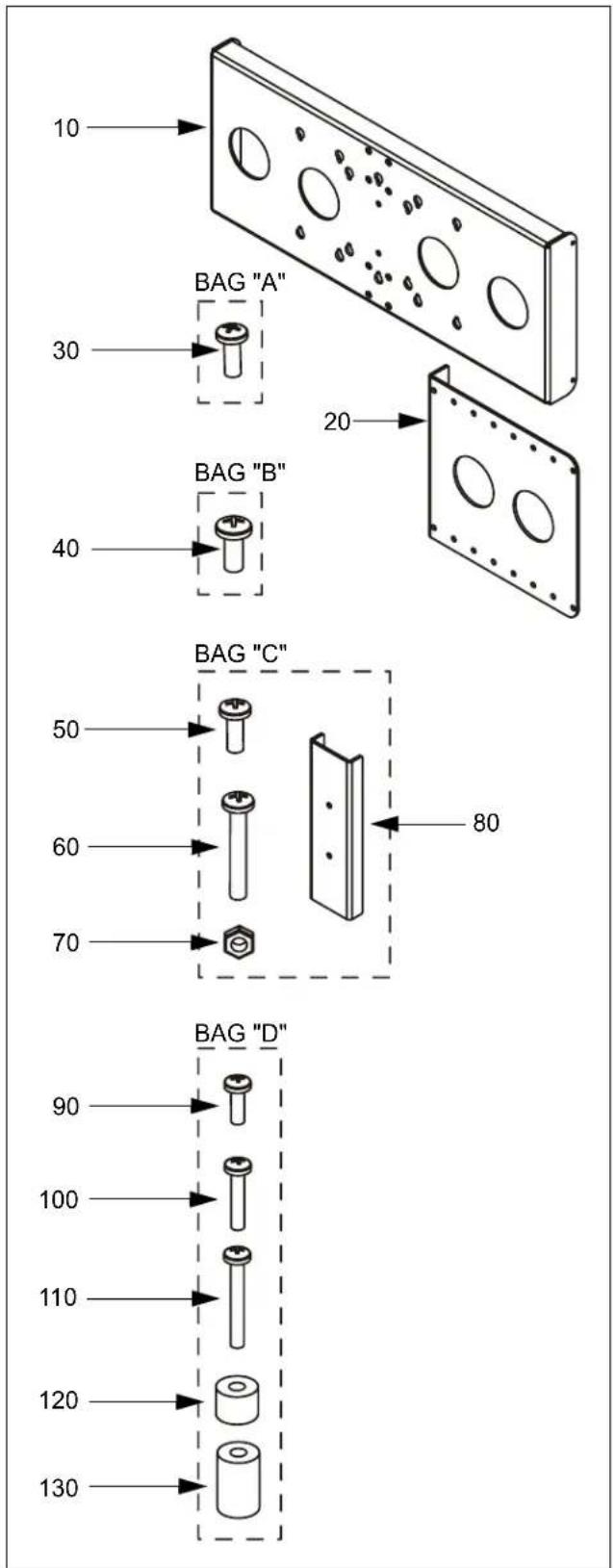
Figure 1: Parts
ASSEMBLY (PART 1)
-
Determine location of bracket (10) in equipment rack. Location is adjustable in 1" increments from approximately 6" depth (within rack) to 1" extension (in front of rack). Consider the following items:
-
Size of display: If display width (i.e., width of case, not screen size) is greater than 17" then bracket (10) must be mounted in front of OR flush with equipment rack. If display width is 17" or less then bracket (10) may be mounted at any location.
- Depth of mount and/or interface (if used).
-
Extent of pitch, roll, yaw, height, and/or extension desired (as applicable for each mount).
-
Using Phillips screwdriver, install screws (50) through brackets (20) into desired threaded holes in bracket (10) (See Figure 2)(See Figure 3). Ensure brackets (10 and 20) are oriented as shown. Tighten screws (50).

Figure 2: Install Side Brackets - 6" Depth

Figure 3: Install Side Brackets - 1" Extension
- Proceed to "INSTALLATION."
INSTALLATION
Determine how display is to be installed to FSA-1015. Four installation options exist:
- OPTION "A" - Installation without Existing Wall Mount:
NOTE: This option REQUIRES a display having mounting holes that are flush with the back surface AND where access to the back of the equipment rack is possible. If one or both of these requirements are not met, proceed to OPTION "B" below.
Applicable to VESA compliant display (75x75mm, 100x100mm, or 100x200mm mounting hole pattern). Non-VESA compliant display also requires installation of interface (purchased separately; contact Chief Manufacturing at 1-800-582-6480 for more information).
- OPTION "B" - Installation without Existing Wall Mount: Applicable to VESA compliant display (75x75mm, 100x100mm, or 100x200mm mounting hole pattern). Non-VESA compliant display also requires installation of interface (purchased separately; contact Chief Manufacturing at 1-800-582-6480 for more information).
- OPTION "C" - Installation with Existing FWD Cynergy Wall Mount: Applicable to VESA compliant display (75x75mm or 100x100mm mounting hole pattern). Non-VESA compliant display also requires installation of interface (purchased separately; contact Chief Manufacturing at 1-800-582-6480 for more information).
- OPTION "D" - Installation with Existing FSR or FTR Fusion Wall Mount: Requires installation of interface (purchased separately; contact Chief Manufacturing at 1-800-582-6480 for more information).
INSTALLATION OPTION "A"
- Install interface to display, if required. See instructions supplied with interface.
- Proceed to "ASSEMBLY (PART 2)."
- Carefully place display face down on protective surface.

CAUTION: Using screws of improper size may damage your display! Proper screws will easily and completely thread into display mounting holes.
- Using Phillips screwdriver, install two (or three, if applicable) screws (90) completely into the upper display mounting holes, then back out 4 full turns (See Figure 4).
NOTE: Do NOT install screws (90) into the lower display mounting holes at this time.

Figure 4: Install Upper Display Screws - Flush Mount
- Pick up and orient display/interface so that the screws installed in the previous step fit into the upper mounting holes in bracket (10) (See Figure 5). Lower display firmly into place.

Figure 5: Install Display - Flush Mount
- From the back of the equipment rack, and using Phillips screwdriver, install remaining two (or three, if applicable) screws (90) through bracket (10) into the lower display mounting holes (See Figure 5).
- Tighten all four (or six, if applicable) screws. Do not overtighten!
- Install all cables.
- Installation is complete.
INSTALLATION OPTION "B"
- Install interface to display, if required. See instructions supplied with interface.
-
Carefully place display face down on protective surface.
-
Determine depth of mounting holes relative to the back surface of display.
- Select proper length spacer and screw from table below:
NOTE: All spacers used should be the same length. If recess depths result in multiple spacer lengths, then select the longer spacer.
| IF recess DEPTH is: THEN use spacer: AND screw: | |
| More than zero up to and including 3/8" | 120 (3/8" long) 100 (M4 x 20mm) |
| More than 3/8" up to and including 3/4" | 130 (3/4" long) 110 (M4 x 30mm) |
- Place the selected spacers over each of the mounting holes on the back of the display.
- Pick up and orient the FSA-1015 assembly such that the mounting holes in bracket (10) are aligned with the holes in the spacers (See Figure 6).

Figure 6: Install Display - Recessed Mount

CAUTION: Using screws of improper size may damage your display! Proper screws will easily and completely thread into display mounting holes.
- Using Phillips screwdriver, install four (or six, if applicable) of the selected screws through the mounting holes in bracket (10), through the spacers, into the display.
- Tighten all four (or six, if applicable) screws. Do not overtighten!
- Proceed to "ASSEMBLY (PART 2)."
- Install all cables.
- Installation is complete.
INSTALLATION OPTION "C"
- Install interface to display, if required. See instructions supplied with interface.
- Using Phillips screwdriver and 7/16" wrench, install two screws (60) through #10 washers and wall bracket (supplied with FWD mount), FSA-1015 assembly, and bracket (80), into nuts (70)(See Figure 7). Tighten screws (60).
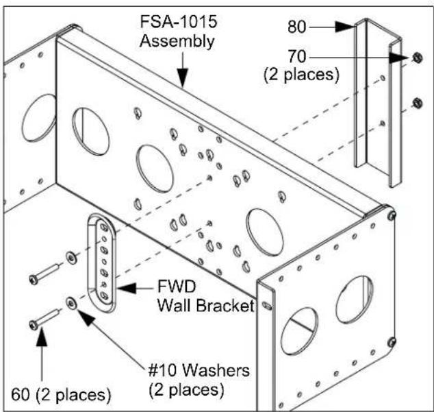
Figure 7: Install FWD Wall Bracket
- Proceed to "ASSEMBLY (PART 2)" below.
- Install display to wall mount. See instructions supplied with FWD mount.
- Install display/wall mount assembly to wall bracket (now installed in equipment rack). See instructions supplied with FWD mount.
- Install all cables.
- Installation is complete.
INSTALLATION OPTION "D"
- Install interface to display. See instructions supplied with interface.
- Using Phillips screwdriver and 7/16" wrench, install four screws (50) through wall mount and bracket (10), into nuts (70)(See Figure 8)(See Figure 9). Tighten screws (50).

Figure 8: Install FSR Wall Mount
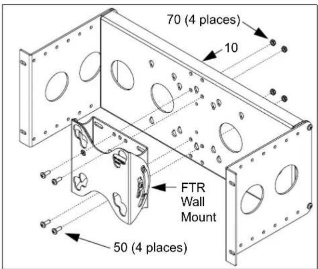
Figure 9: Install FTR Wall Mount
- Proceed to "ASSEMBLY (PART 2)" below.
- Install display to wall mount (now installed in equipment rack). See instructions supplied with FSR/FTR mount.
- Install all cables.
- Installation is complete.
ASSEMBLY (PART 2)

WARNING: Failure to use proper fasteners can result in serious personal injury or damage to equipment! Screws (30 and 40) supplied for convenience only.
- Using Phillips screwdriver install FSA-1015 assembly to equipment rack using four screws (30, 40, or other fasteners as applicable)(See Figure 10). Tighten fasteners.

Figure 10: Install FSA-1015 to Equipment Rack
- Return to INSTALLATION OPTION "A," "B," "C," or "D," as applicable.



- INSTALLATION INSTRUCTIONS
- 19" EQUIPMENT RACK ACCESSORY
- Model: FSA-1015
- Specifications:
- BEFORE YOU BEGIN
- IMPORTANT WARNINGS AND CAUTIONS!
- DIMENSIONS
- TOOLS REQUIRED FOR INSTALLATION
- PARTS
- ASSEMBLY (PART 1)
- INSTALLATION
- INSTALLATION OPTION "A"
- INSTALLATION OPTION "B"
- INSTALLATION OPTION "C"
- INSTALLATION OPTION "D"
- ASSEMBLY (PART 2)
Brand : Chief
Model : FSA1015B
Category : Wall mount for screen