ioLogik E2262 - Industrial Automation Moxa - Free user manual and instructions
Find the device manual for free ioLogik E2262 Moxa in PDF.

User questions about ioLogik E2262 Moxa
0 question about this device. Answer the ones you know or ask your own.
Ask a new question about this device
Download the instructions for your Industrial Automation in PDF format for free! Find your manual ioLogik E2262 - Moxa and take your electronic device back in hand. On this page are published all the documents necessary for the use of your device. ioLogik E2262 by Moxa.
USER MANUAL ioLogik E2262 Moxa
Click&Go V2 User's Manual
Second Edition, December 2008
www.moxa.com/product
MOXA®
© 2008 Moxa Inc. All rights reserved. Reproduction without permission is prohibited.
Click&Go V2 User's Manual
The software described in this manual is furnished under a license agreement, and may be used only in accordance with the terms of that agreement.
Copyright Notice
Copyright © 2008 Moxa Inc.
All rights reserved.
Reproduction without permission is prohibited.
Trademarks
MOXA is a registered trademark of Moxa Inc.
All other trademarks or registered marks in this manual belong to their respective manufacturers.
Disclaimer
Information in this document is subject to change without notice, and does not represent a commitment on the part of Moxa.
Moxa provides this document “as is,” without warranty of any kind, either expressed or implied, including, but not limited to, its particular purpose. Moxa reserves the right to make improvements, and/or changes to this manual, or to the products, and/or the programs described in this manual, at any time.
Information provided in this manual is intended to be accurate, and reliable. However, Moxa assumes no responsibility for its use, or for any infringements on the rights of third parties that may result from its use.
This manual might include unintentional technical or typographical errors. Changes are made periodically to the information herein to correct such errors, and these changes are incorporated into new editions of the manual.
Technical Support Contact Information www.moxa.com/support
Moxa Americas:
Toll-free: 1-888-669-2872
Tel: +1-714-528-6777
Fax: +1-714-528-6778
Moxa China (Shanghai office):
Toll-free: 800-820-5036
Tel: +86-21-5258-9955
Fax: +86-10-6872-3958
Moxa Europe:
Tel: +49-89-3 70 03 99-0
Fax: +49-89-3 70 03 99-99
Moxa Asia-Pacific:
Product and Software Support 1-3
Difference in Programming Method and Space.... 1-4
Difference in IF Conditions 1-5
Difference in THEN/ELSE Actions 1-6
Click&Go Version Check.... 1-7
Chapter 2. Getting Started ......2-1
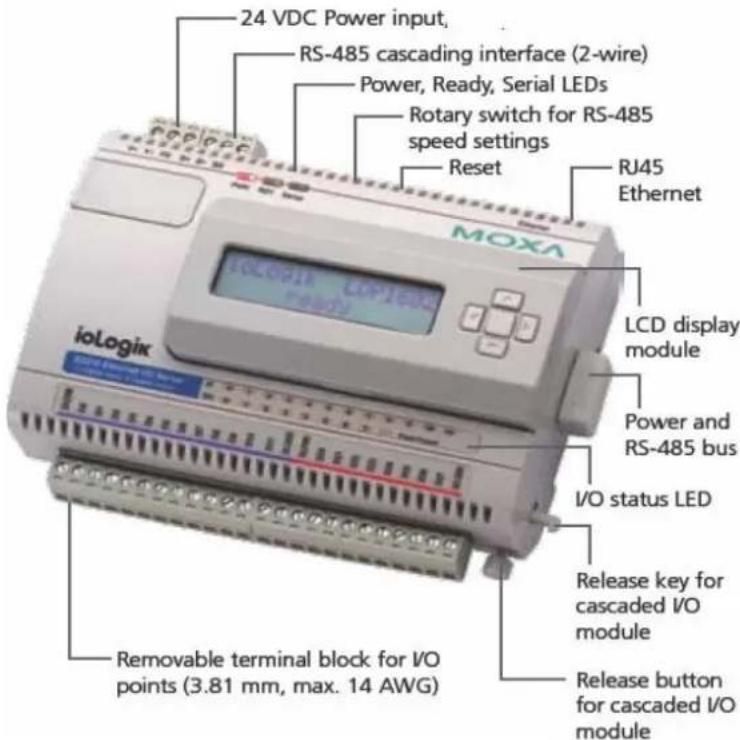
Hardware Connection 2-2
System Requirements 2-2
Connecting to the Network.... 2-3
Optional Liquid Crystal Display Module (LCM) 2-3
Adding More I/O Channels 2-3
Connecting the I/O Device 2-4
Software Preparation 2-4
ioAdmin 3.x Installation....2-4
Firmware Update 2-7
Reset to Factory Default.... 2-8
Chapter 3. Click&Go V2 Developing Process ....3-1
Click&Go V2 Development Process 3-2
I/O Configuration 3-2
Configurable DIO Channel Mode Selection.... 3-2
Digital Input Mode Selection.... 3-3
Digital Output Mode Selection 3-4
Analog Input Mode Selection 3-5
Analog Output Mode Selection 3-6
Temperature Input Mode Selection 3-6
Alias Name Configuration.... 3-8
Testing the I/O Channels 3-9
Define Global Variables.... 3-9
Internal Register Settings.... 3-10
Timer Settings.... 3-10
SNMP Trap Server 3-11
E-Mail Server 3-11
Active Message Server 3-12
Work with Logic 3-13
Click&Go Logic Basics....3-13
IF Conditions 3-16
More Info on Repeat Interval vs. Edge Detection 3-26
THEN/ELSE Actions.... 3-29
Peer-to-Peer Function 3-42
Activating the Rule-set 3-45
Download, Restart and Run.... 3-45
Rule-set Management Bar 3-45
Import/Export Configuration 3-46
Using ioAdmin to Import/Export Configuration 3-46
Using TFTP to Import/Export Configuration 3-48
Chapter 4. Click&Go Examples and Applications ....4-1
Click&Go Rule 101 4-2
IF-THEN-ELSE....4-2
Where there is an ON Logic, there should be an OFF Logic.... 4-2
Rules are Running in a Loop 4-2
Using the Timer Function.... 4-3
Heartbeat or Repeat Actions.... 4-3
ON-Delay 4-4
OFF-Delay 4-5
Using Internal Registers 4-5
Soft-key 4-5
Remote Control....4-5
Programming Examples 4-6
Local I/O Control....4-6
Active I/O Messages....4-7
Peer-to-Peer I/O 4-9
Applications_1....4-12
Project Background 4-12
Application Requirements 4-12
Moxa Solution 4-12
Solution Benefits 4-12
Additional Features.... 4-13
System Diagram 4-13
Click&Go Programming Example.... 4-14
Applications_2....4-15
Project Background 4-15
Application Requirements 4-15
Moxa Solution 4-15
Solution Benefits 4-15
Additional Features.... 4-16
System Diagram 4-16
Click&Go Programming Example.... 4-16
Applications_3....4-18
Project Background 4-18
Application Requirements 4-18
Moxa Solution 4-18
Solution Benefits 4-18
Additional Features.... 4-19
System Diagram 4-19
Click&Go Programming Example.... 4-20
Applications_4.... 4-21
Project Background 4-21
Application Requirements 4-21
Moxa Solution 4-21
Solution Benefits 4-21
Additional Features.... 4-22
System Diagram 4-22
Click&Go Programming Example.... 4-22
Applications_5 4-24
Project Background 4-24
Application Requirements 4-24
Moxa Solution 4-24
Solution Benefits 4-24
Additional Features....4-25
System Diagram 4-25
Click&Go Programming Example....4-25
Applications_6 4-27
Project Background 4-27
Application Requirements 4-27
Moxa Solution 4-27
Solution Benefits 4-27
Additional Features....4-28
System Diagram 4-28
Click&Go Programming Example....4-29
Applications_7 4-30
Project Background 4-30
Application Requirements 4-30
Moxa Solution 4-30
Solution Benefits 4-31
Additional Features....4-31
System Diagram 4-31
Click&Go Programming Example_Site 4-32
Click&Go Programming Example_Central 4-35
Appendix A. Internal Registers – Modbus/TCP Address Mappings......A-1
ioLogik E2210, E2212 and E2214....A-1
4xxxx Read/Write Registers (Functions 3, 6, 16)...... A-1
ioLogik E2240, E2242, E2260 and E22262 A-2
4xxxx Read/Write Registers (Functions 3, 6, 16)...... A-2
Click&Go ^TM is the local control logic for the Moxa ioLogik series Active Ethernet I/O server, which transforms the ioLogik series from a traditional passive Ethernet I/O to an active Ethernet I/O. With Click&Go, users have complete control over what, when and where they transmit.
The following topics are covered in this chapter:
Overview
□ Click&Go V2 Features
Product and Software Support
- Difference in Programming Method and Space
▶ Difference in IF Conditions
▶ Difference in THEN/ELSE Actions
➢ Click&Go Version Check
Overview

Everybody can be a programmer! Moxa's Click&Go local control logic for the ioLogik Active Ethernet I/O server eliminates the cumbersome programming generally required for data acquisition, alarm messaging, and local control tasks. No knowledge of C-language or PLC ladder is required for field applications. Instead, users familiar with IF-THEN-ELSE statements will have no problem understanding the Click&Go interface and will be able to control I/O channels and alarm messaging after a few simple steps. The configuration utility also makes the control process easy to define and configure. Simply download the control logic to the ioLogik Active Ethernet I/O server and Click&Go will be ready-to-go in no time.
Click&Go performs various functions including local I/O control, remote output control, alarm generation and messaging, and event-driven or time-based I/O status reporting.
Click&Go eliminates the need for host computers to continually poll I/O devices for status. Instead, the server itself is able to monitor the status of each I/O device and take the appropriate action when the I/O status satisfies a user-defined condition. For example, users may need to configure the Moxa ioLogik Active Ethernet I/O servers to send a TCP/UDP message only when the switch attached to DI-0 is turned on. This event-based structure results in a much improved response time and a much reduced load on the host computer's CPU and on network bandwidth.
Simple IF–THEN–ELSE statements are used to specify conditions that are required for certain actions to take place. Up to three conditions, three actions and three opposite actions (ELSE) can be combined in a rule, and you can define up to 24 rules. Supported actions include sending SNMP traps or TCP/UDP messages to up to 10 hosts at a time.
Click&Go can also be used to map an input channel on one Moxa ioLogik Active Ethernet I/O server to an output channel on another ioLogik for peer-to-peer I/O communication. Up to five different IP addresses can be entered as the output destination. Peer-to-peer I/O provides a very flexible and easy way to extend I/O signals or connect remote on/off switches. It can be used, for example, to replace or extend the wiring of PLC or DCS systems over Ethernet.
Click&Go V2 Features
24 Rules for IF-THEN-ELSE Style Programming
Users do not require any programming experience to use Click&Go. The easy and straightforward IF-THEN-ELSE programming style greatly simplifies the development and installation of I/O applications. With 24 IF-THEN-ELSE rules pre-installed and up to 3 IF conditions and 3 THEN/ELSE outputs or network actions per rule, Click&Go is suitable for most remote monitoring and alarm applications.
Local Monitoring and Local Control
Click&Go can continually monitor the local I/O status for each input channel, trigger the status, or direct it to local output channels.
Remote Control and Control by Remote
Click&Go is capable of accepting control commands from a remote host or an ioLogik. In addition, it can send out commands to remotely control another ioLogik.
Time-stamped Active Messaging
All alarms, messages, e-mail notices, and TCP, UDP, and SNMP traps are time-stamped with the exact time of the events.
Peer-to-peer I/O
Peer-to-peer I/O can be used to set up I/O mapping over Ethernet from the DI channel on one ioLogik to the DO channel on another ioLogik.
Product and Software Support
Although the current ioLogik E2000 series comes pre-installed with the original Click&Go V1 local control logic, the new Click&Go V2 offers more powerful functions to meet the needs of different applications. This User's Manual describes all the functions of Click&Go V2, which comes with the following products.
| Product Category | Model | Communication Interface | Input/Output | Firmware Version | ioAdmin Version |
| Active Ethernet I/O | ioLogik E2210 | Ethernet 12 DI, 8DO | 3.0 ↑ | V3.0 ↑ | |
| ioLogik E2212 | 8 DI, 8DO, 4 DIO | 3.0 ↑ | V3.0 ↑ | ||
| ioLogik E2214 | 6 DI, 6 Relay | 3.0 ↑ | V3.0 ↑ | ||
| ioLogik | E2240 | 8 AI, 2 A0 | 3.0 ↑ | V3.1 ↑ | |
| ioLogik | E2242 | 4 AI, 12 DIO | 3.0 ↑ | V3.1 ↑ | |
| ioLogik | E2260 | 6 RTD, 4 DO | 3.0 ↑ | V3.1 ↑ | |
| ioLogik | E2262 | 8 TC, 4 DO | 3.0 ↑ | V3.1 ↑ |
The easiest way to upgrade a current ioLogik without purchasing a new device is by installing the latest firmware and ioAdmin utility. There is no need to reconfigure earlier Click&Go rule-sets that are still running on your device.
[Moxa Active Ethernet I/O - ioLogik E2000 Series Products]
Difference in Programming Method and Space
| Programming Method Programming Space | |
| Click&Go V1.x IF-THEN 16 Rules | |
| Click&Go V2.x IF-THEN-ELSE 24 Rules | |
Difference in IF Conditions
| Click&Go V1.0 * | ^1 Click&Go V1.1 Click&Go V2.x | ||
| Input Channel Status |  |  |  |
| Digital Input Counter |  |  |  |
| Timer Trigger |  |  |  |
| ^*2 Relay Counter |  |  |  |
| ^*1 Delay Timer |  |  | |
| Timer |  | ||
| Internal Register |  |  | |
| Remote Action |  | ||
| Schedule |  | ||
| Host Connection Fail |  | ||
Difference in THEN/ELSE Actions
| Click&Go | V1.0 Click&Go V1.1 | Click&Go V1.x | |
| Input Channel Control |  |  |  |
| Digital Input Counter Reset |  |  |  |
| *2Relay Counter Reset |  |  | |
| SNMP Trap |  |  |  |
| Active Message |  |  |  |
 |  |  | |
| *1Delay Timer |  | ||
| Timer |  | ||
| *1Internal Register |  |  | |
| Remote Action |  | ||
| CGI Command |  |
NOTE
- Click&Go V1.1 only supports ioLogik E2242 firmware V1.x. The definition of "Internal Register" and the "Delay Timer" is slightly different from the latest Click&Go V2. The latest Timer covers the function of the earlier Timer Trigger and the latest Internal Register covers the earlier ones.
- These specific IF conditions and THEN/ELSE actions are only supported on the ioLogik E2214 Relay Module.
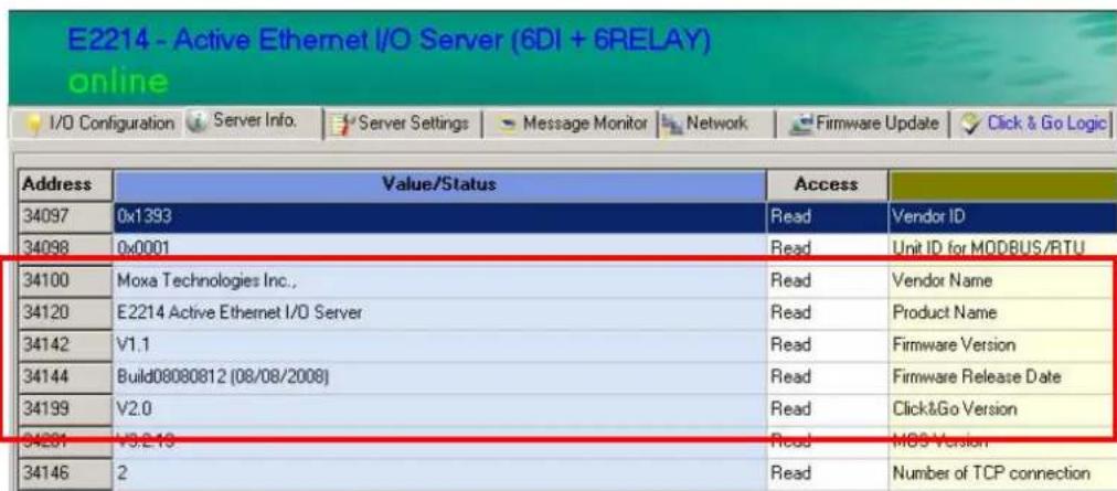
Click&Go Version Check
The best way to verify the current version of the firmware or Click&Go is to run the ioAdmin configuration utility. After a broadcast search for the ioLogik on the network, ioAdmin displays the information on its “Server Info.” tab. Refer to the related sections of the product user’s manual for detailed information on software installation and other operations such as firmware upgrade.
This chapter describes how to set up and prepare for Click&Go programming.
The following topics are covered in this chapter:
Hardware Connection
System Requirements
Connecting to the Network
➢ Optional Liquid Crystal Display Module (LCM)
➢ Adding More I/O Channels
Connecting the I/O Device
□ Software Preparation
➢ ioAdmin 3.x Installation
➢ Firmware Update
➢ Reset to Factory Default
Hardware Connection
System Requirements
A fully developed system should consist of the following components:
- A PC or laptop computer with Windows operating system (Win2000/XP or later).
- A power supply, 12 to 48 VDC with more than 400 mA output should be used.
- An Ethernet switch or a cross-over/direct Ethernet cable.
- ioAdmin configuration utility V3.0 or later.
- Proper firmware on the ioLogik products.
- Electric sensors or alarm lights for testing purpose.
flowchart
graph TD
    A["MOXA"] -->|AC Power| B["ioLogik E2000"]
    C["Windows PC"] -->|Ethernet Cable| B
    B --> D["Sensors and Alarms"]
    style A fill:#f9f,stroke:#333
    style B fill:#ccf,stroke:#333
    style C fill:#cfc,stroke:#333
    style D fill:#fcc,stroke:#333
Connecting to the Network
-
Connect the ioLogik to the host PC with an Ethernet cable. For initial configuration, it is recommended that the ioLogik E2000 series product be configured using a direct connection to a host computer rather than remotely over the Internet.
-
Set the host PC's IP address to 192.168.127.xxx. (xxx: from 001 to 253). In Windows, you can adjust this setting through the Control Panel.
| Default IP Address | Default Netmask | Default Gateway |
| 192.168.127.254 | 255.255.255.0 | None |
- Use ioAdmin configuration utility to detect the ioLogik. Once the ioLogik has been detected, modify the settings as needed for your network environment, then restart the server.
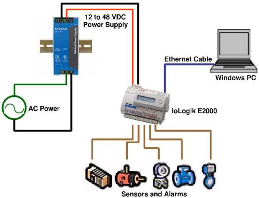
Optional Liquid Crystal Display Module (LCM)
The ioLogik E2000 series supports an optional hot-pluggable Liquid Crystal Module (LCM) for field management and configuration. The LCM can display network and I/O settings such as digital input mode and value. The ioLogik E2000 series' IP address and netmask can also be configured using the LCM, and one LCM can be used to maintain and configure multiple ioLogik products.
Optional Accessories
• LDP1602 ioLogik LCM (Liquid Crystal Display Module)

natural_image
White electronic device with a green screen and control buttons (no visible text or symbols)Adding More I/O Channels
A cost-effective way to add more I/O channels to your Ethernet-based ioLogik E2000 series is to attach an appropriate RS-485 ioLogik R2000 series I/O. However, it is important to remember that Click&Go local control logic does NOT apply to the expanded channels from an external ioLogik.

ATTENTION
Extension I/O channels from another ioLogik R2000 will NOT be a part of Click&Go logic, those additional channels can only be polled by a remote host computer.
Connecting the I/O Device
The ioLogik series is equipped with multiple input and multiple output channels. These channels are designed to offer greater flexibility for connecting I/O devices. The sensor type determines your wiring approach so please refer to the specific I/O model's user manual for detailed wiring instructions.

ATTENTION
For wiring reference, refer to the specific user's manual for each product.
Software Preparation
ioAdmin 3.x Installation
ioAdmin is a Windows utility provided for the configuration and management of ioLogik series products, including the programming of the Click&go logics. ioAdmin can be used from anywhere on the network to monitor and configure ioLogik. You can also configure some of the settings through the web console or optional LCM.
Be sure to always use a version higher than V3.0.
Note that configuration options are not available until you log in as an administrator.
![MOXA iodoAdmin Host [192.168.19.201] i o log E2210 192.168.19.123 192.168.19.127 192.168.19.25 192.168.19.27 192.168.19.30 E2212 E2214 192.168.127.850 192.168.19.00 E2240 E2360 E2214 - Active Ethernet Server (6DI + 6RELAY) on-line UO Configurion Server Info Server Settings Message Monitor MOXA ioLogic Channel Mode Status Fitter Trigger Channel Mode Status Low High [00]:00 DI OFF 50.0 ms -- [00]:00 DO ON -- -- [04]:01 DI OFF 50.0 ms -- [00]:01 DO ON -- -- [04]:02 DI OFF 50.0 ms -- [00]:02 DO ON -- -- [04]:03 DI OFF 50.0 ms -- [00]:03 DO ON -- -- [04]:04 DI OFF 50.0 ms -- [00]:04 DO ON -- -- [04]:05 DI OFF 50.0 ms -- [00]:05 DO ON -- -- 6 E2214 DO space slot 2sec Ready 115280.Nemo 8.1 0:00:07:47 下午 04:24:30](/content/2026/06/1189123/images/1842baf5763611c57f35336ba0d5ce932e6049abb568239e853f769eddd9a8bc.jpg)
| ioAdmin Main Screen | |
| 1. Title | 2. Menu Bar |
| 3. Quick Link | 4. Navigation Panel |
| 5. Main Window | 6. Sync. Rate Status |
| 7. Status Bar |
The ioAdim can be found in the product CD, or download the latest version on Moxa's Website.
- Installation from CD: Insert the Document and Software CD into the host computer. In the Software/ioAdmin directory of the CD, locate and run SETUP.EXE. The installation program will guide you through the installation process and install the ioAdmin utility.
- Open ioAdmin: After installation is finished, run ioAdmin from the Windows Start menu: Start →Program Files →MOXA →IO Server →Utility → ioAdmin.
- Search the network for ioLogik: When ioAdmin is started, it will automatically run the auto search program. Or find it on the menu bar, select System → Auto Scan Active Ethernet I/O. A dialog window will appear. Click Start Search to begin searching for your unit.
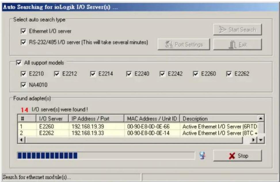
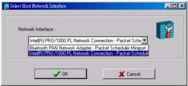
NOTE
If there are multiple network interfaces in the host computers, be sure to select the correct one before searching.

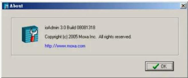
ATTENTION
ioAdmin V3.0 or later should always be installed first before starting the configuration or programming.. Find the version information at the ioAdmin tool bar, click on Help/About.
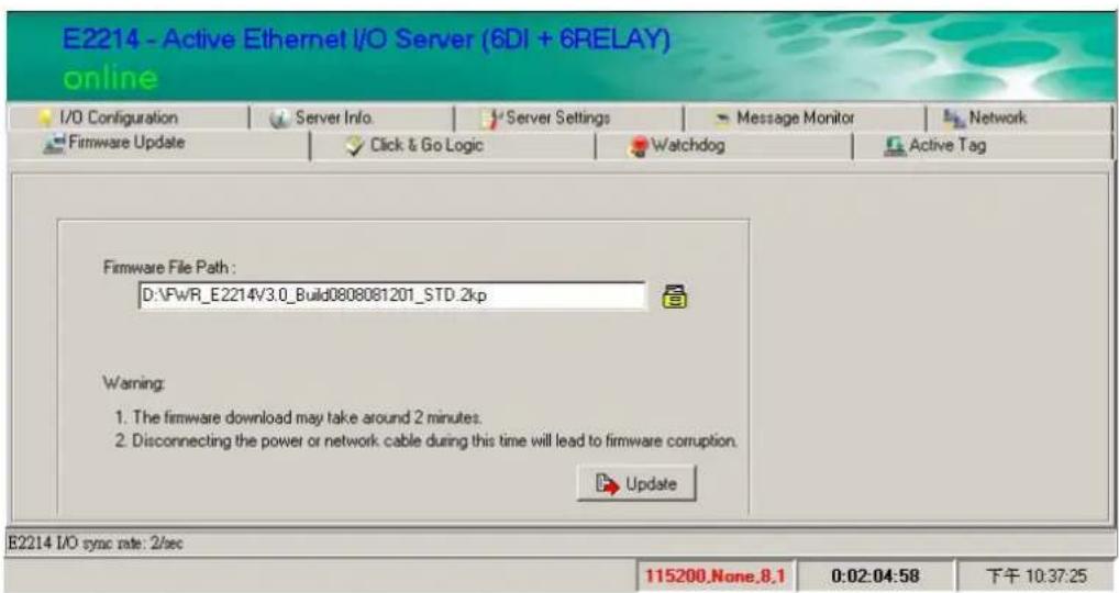
Firmware Update
Firmware upgrade will be necessary to have the latest function support on the ioLogik products (see Chap. 1). To do so, the Firmware Update tab is available after you log in ioAdmin utility as an administrator. In the Firmware Upgrade tab, enter the path to the firmware file or click on the icon to browse for the file. Click Update to update the ioLogik firmware. The wizard will lead you through the process until the ioLogik is restarted.
Firmware upgrade with a jump version for specific ioLogik models may be required.
| Model | Start Version | Jump Version | Final Version |
| ioLogik E2210 V1.x V2.0 V3.x | |||
| ioLogik E2212 V1.0 V1.1 V3.x | |||
| ioLogik E2240 V1.x V2.2 V3.x | |||
| ioLogik E2214, E2242, ioLogik E2260, E2262 | V1.x | N/A | V3.x |
For ioLogik E2210, E2212 and E2240, it is recommended to upgrade the jump version first, and then upgrade again to the final version that supports Click&Go V2. For the rest of the models, firmware upgrade can be performed directly to the latest version.

ATTENTION
Do not interrupt the firmware update process! An interruption in the process might result in your device becoming unrecoverable.
After the firmware is updated, the ioLogik will restart and you will have to log in again to access administrator functions.
The firmware on any attached I/O expansion module, such as an ioLogik R2000 server, must be updated over the RS-485 bus. Firmware on cascaded modules cannot be updated over Ethernet.
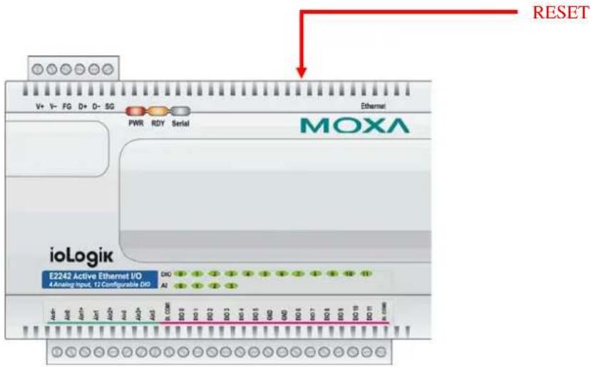
Reset to Factory Default
If there is an ioLogik that has been configured before, it is recommended to reset it to the factory default. Performing this task, users may right click on the selected ioLogik in the ioAdmin, click on the "Load Factory Default" link on the ioLogik's web console using a browser, or, press the RESET button on the ioLogik for 10 seconds.
In this chapter, we explain each function of the Click&Go V2 programming logic and how to develop the process.
The following topics are covered in this chapter:
□ Click&Go V2 Development Process
☐ I/O Configuration
➢ Configurable DIO Channel Mode Selection
▶ Digital Input Mode Selection
▶ Digital Output Mode Selection
▶ Analog Input Mode Selection
▶ Analog Output Mode Selection
➢ Temperature Input Mode Selection
▶ Alias Name Configuration
➢ Testing the I/O Channels
☐ Define Global Variables
▶ Internal Register Settings
Timer Settings
▶ SNMP Trap Server
E-Mail Server
Active Message Server
□ Work with Logic
Click&Go Logic Basics
▶ IF Conditions
➢ More Info on Repeat Interval vs. Edge Detection
THEN/ELSE Actions
▶ Peer-to-Peer Function
□ Activating the Rule-set
➢ Download, Restart and Run
☐ Rule-set Management Bar
□ Import/Export Configuration
➢ Using ioAdmin to Import/Export Configuration
➢ Using TFTP to Import/Export Configuration
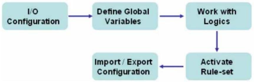
Click&Go V2 Development Process
After searching and setting up the IP address of an ioLogik Ethernet I/O server, Click&Go V2 logic can be developed by following the procedures below:
flowchart
graph TD
    A["I/O Configuration"] --> B["Define Global Variables"]
    B --> C["Work with Logics"]
    C --> D["Activate Rule-set"]
    D --> E["Import / Export Configuration"]
I/O Configuration
The ioLogik series products are embedded with various types of I/O channels and the mode of each input/output channel must be configured first. The channels are divided into digital inputs, digital outputs, analog inputs, analog output, and virtual channels.
Configurable DIO Channel Mode Selection
For the models that support the configurable DIO channels, configure the specific DIO to DI or DO to meet the requirements.
| Model Available | Number of Configurable DIO Channels | Mode Selection: Digital Input | Mode Selection: Digital Output |
| ioLogik E2212 4 |  |  | |
| ioLogik E2242 12 |  |  |
When logged in as an administrator, double click on a channel in the I/O Configuration tab to configure that channel's settings. A window will open with configuration options for that channel. Each DIO channel will be configured to act as either a DI or DO channel, according to the Power On Settings. To switch between DI and DO channel operation, select the desired mode in the I/O Direction field under Power On Settings. After clicking Apply, you will need to restart the ioLogik for the new setting to take effect.


ATTENTION
Before performing any further configuration or programming, switching between DI and DO channel requires restarting the ioLogik for the new setting to take effect.
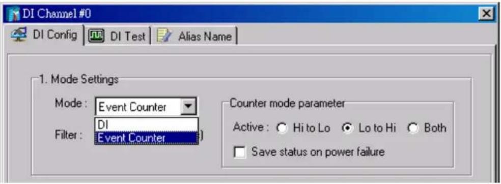
Digital Input Mode Selection
A DI channel can be set to "DI" or "Event Counter" mode. In DI mode, it connects to dry/wet contacts.
In Event Counter mode, the channel accepts limit or proximity switches and counts events according to the ON/OFF status. When “Lo to Hi” is selected, the counter value increases when the attached switch is pushed. When “Hi to Lo” is selected, the counter value increases when the switch is pushed and released.
| Mode Available | Number of Digital Input Channels | Mode Selection: DI | Mode Selection: Event Counter |
| ioLogik E2210 12 |  |  | |
| ioLogik E2212 8 + 4 DIO |  |  | |
| ioLogik E2214 6 |  |  | |
| ioLogik E2242 12 DIO |  |  |
When logged in as an administrator, double click on a channel in the I/O Configuration tab to configure that channel's settings. A window will open with configuration options for that channel. Each DI channel will be configured to act as either a DI or Event Counter channel, according to the Mode Settings. To switch between DI and Event Counter channel operation, select the desired mode in the Mode Settings.

ATTENTION
On this tab, be sure to select "Start" for the Counter Mode Parameters on the "Power On Settings" to enable the Event Counter channel.
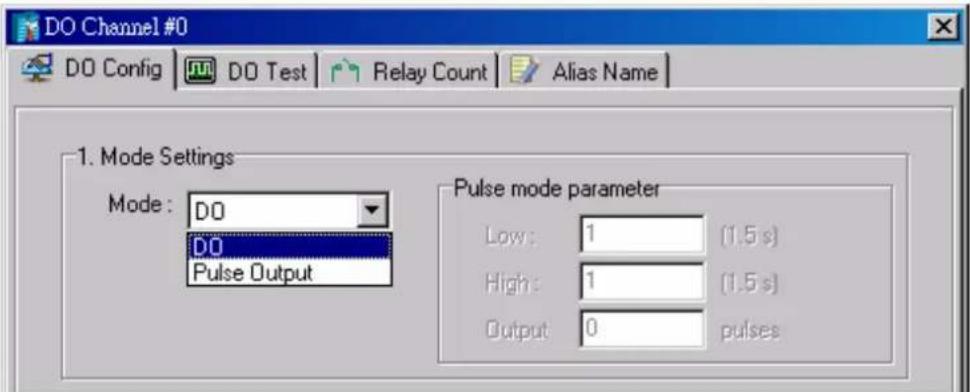
Digital Output Mode Selection
A DO channel can be set to "DO" or "Pulse Output" mode.
| Mode Available | Number of Digital Output Channels | Mode Selection: DO | Mode Selection: Pulse Output |
| ioLogik E2210 8 |  |  | |
| ioLogik E2212 8 + 4 DIO |  |  | |
| ioLogik E2214 6 Relay |  |  | |
| ioLogik E2242 12 DIO |  |  | |
| ioLogik E2260 4 DO |  |  | |
| ioLogik E2262 4 DO |  |  |
When logged in as an administrator, double click on a channel in the I/O Configuration tab to configure that channel's settings. A window will open with configuration options for that channel. Each DO channel will be configured to act as either a DO or Pulse Output channel, according to the Mode Settings. To switch between DO and Pulse Output channel operation, select the desired mode in the Mode Settings.
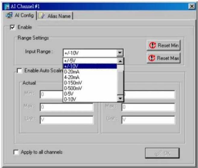
Analog Input Mode Selection
Analog input channels can be divided into voltage and current. For different models, the support of the voltage and current measurement are not the same.
| Mode Available | Number of Analog Input Channels | Mode Selection: Voltage | Mode Selection: Current |
| ioLogik E2240 8 | ±150 mV, ±500 mV, ±5 V, ±10 V | 0 to 20 mA, 4 to 20 mA | |
| ioLogik E2242 4 | ±150 mV, 0 to 150 mV, ±500 mV, 0 to 500 mV, ±5 V, 0 to 5 V, ±10 V, 0 to 10 V | 0 to 20 mA, 4 to 20 mA |
When logged in as an administrator, double click on a channel in the I/O Configuration tab to configure that channel's settings. A window will open with configuration options for that channel. Each AI channel will be configured to measure either voltage or current according to the Range Settings.
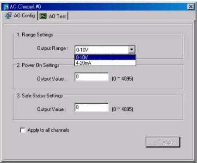
Analog Output Mode Selection
The only model that currently provides analog output channels is ioLogik E2240, which provides both voltage and current output.
| Mode Available | Number of Analog Output Channels | Mode Selection: Voltage | Mode Selection: Current |
| ioLogik E2240 2 0 to 10 V 4 to 20 mA |
When logged in as an administrator, double click on a channel in the I/O Configuration tab to configure that channel's settings. A window will open with configuration options for that channel. Each AO channel will be configured to output either voltage or current according to the Range Settings.
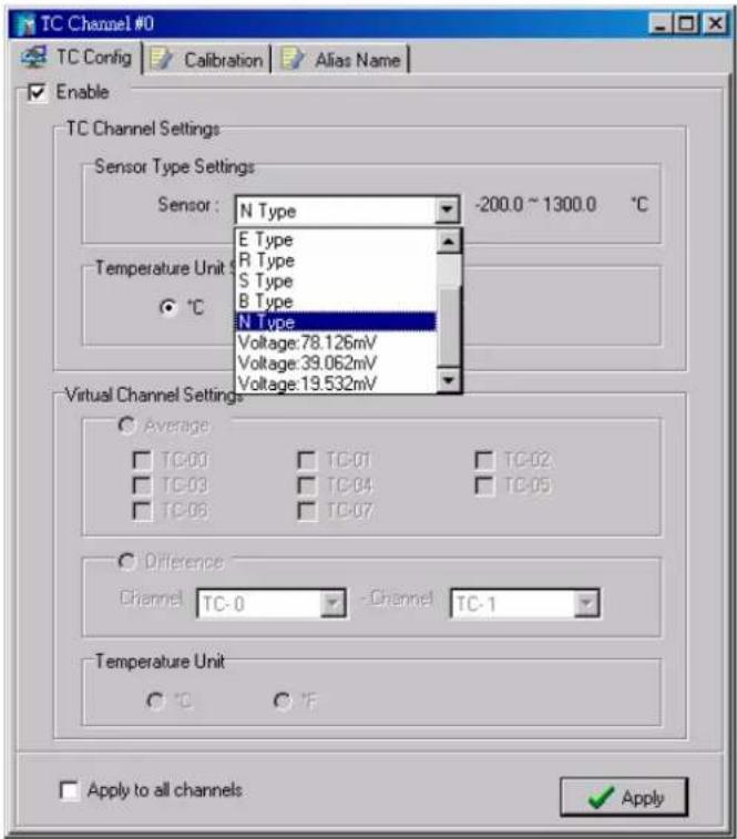
Temperature Input Mode Selection
Thermocouple (TC) and resistance temperature detector (RTD) sensors are mostly used to perform temperature measurements. For Moxa ioLogik Active Ethernet I/O servers, selecting the temperature input modes is equal to selecting the sensor types.
| Mode Available | Number of Temperature Input Channels | Sensor Type Selection: |
| ioLogik E2260 6 RTD | Pt100, Pt200, Pt500, Pt1000, JPt100, JPt200, JPt500, JPt1000, Ni 100, Ni 200, Ni 500, Ni 1000, Ni 120, Resistance (1-310 mΩ), Resistance (1-620 mΩ), Resistance (1-1250 mΩ), Resistance (1-2200 mΩ) | |
| ioLogik E2262 8 TC | J, K, T, E, R, S, B, N Type and 78.126/39.062/19.532mV |
When logged in as an administrator, double click on a channel in the I/O Configuration tab to configure that channel's settings. A window will open with configuration options for that channel. Each temperature input channel will be configured to support different types of sensors according to the RTD Channel Settings (ioLogik E2260) or TC Channel Settings (ioLogik E2262).
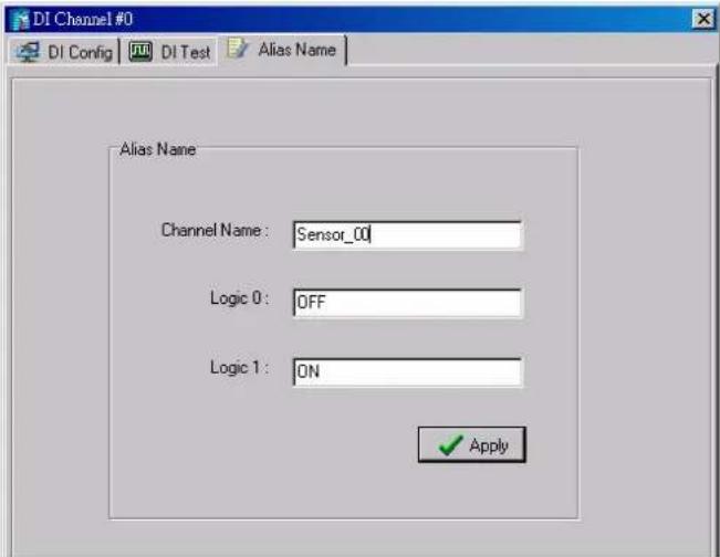
Alias Name Configuration
Alias Name helps users configure the alias of an input or an output channel and define the status for logic 0/1 to be On/Off or vice versa. The Alias can be monitored by the ioAdmin utility, or can be queried using a user-defined program based on the Moxa MXIO library, or a standard Modbus/TCP protocol. As for Click&Go programming, the alias name will be redirected to the logic when the specified channel is selected. For example, the fist DI Channel is displayed as "DI-0" in the Click&Go. If alias name is modified to "Door_0", users can directly recognize the usage of the DI-0 as "Door_0" when programming.
When logged in as an administrator, double click on a channel in the I/O Configuration tab to configure that channel's settings. A window will open with configuration options for that channel. Alias name of each input/output channel can be configured by selecting the Alias Name tab.

ATTENTION
It is strongly recommended to configure the alias name for the used I/O channel before performing any further configuration or programming.
Testing the I/O Channels
Each I/O channel can be tested or monitored individually. When logged in as an administrator, double click on a channel in the I/O Configuration tab to configure that channel's settings. A window will open with configuration options for that channel. Tests can be done by opening the channel's configuration window and selecting the Test tab.
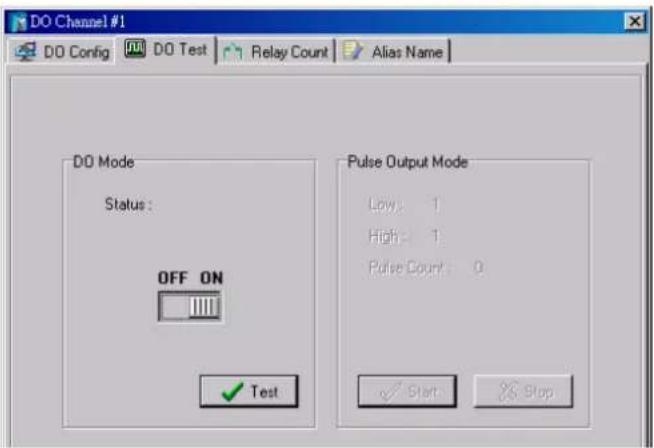
In the Test tab, you can see how a channel's status affects or is affected by the attached device. For output channels, you can set the on/off status, start and stop a pulse, or output a voltage or current. For input channels, you can monitor the attached device's on/off status, counter, or input voltage/current.
Define Global Variables
Global Variables include the settings of "Internal Register Settings", "Timer Settings", "SNMP Trap Server", "E-Mail Server" and "Active Message Server". If these functions are going to be used in Click&Go V2 rule-set, default configuration must first be set in the Global Variable Menu Bar.
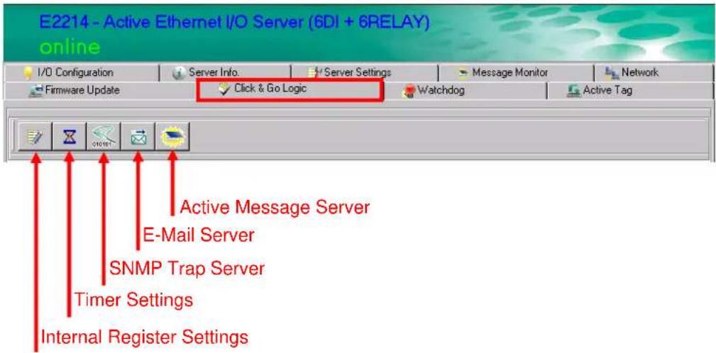
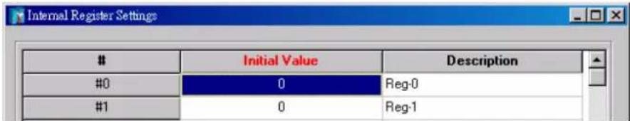
Internal Register Settings
Internal Register is a flag that can be used with the Click&Go logic internally or externally. The 24 sets of the internal registers can be polled and controlled by a SCADA software using standard Modbus/TCP format, or be implemented to redirect the result of one Click&Go logic to another.
Default value of an internal register is "0".
| Register Number Initial Value | |
| Internal Register Reg-0 to Reg-23 *0 to 255 |
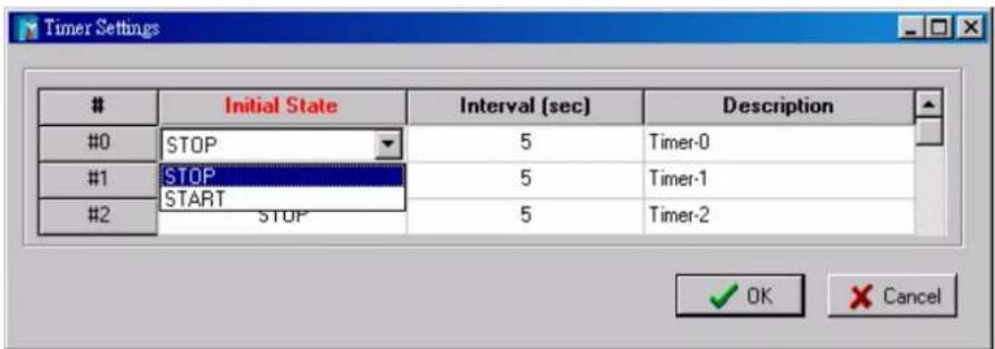
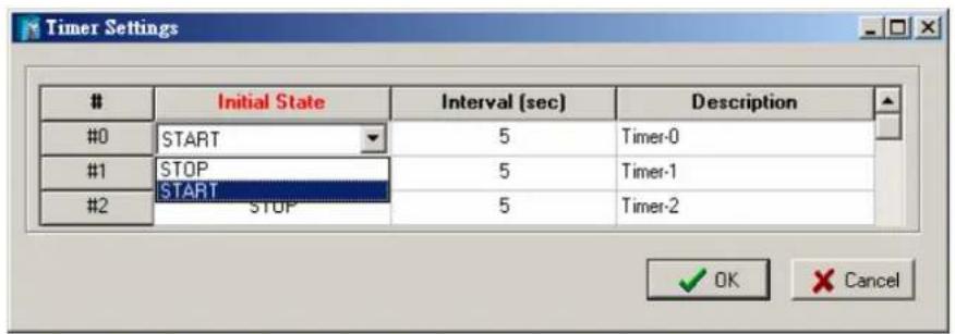
Timer Settings
The Timer function allows users to delay an action, to trigger an action to run, or repeat an action. A timer is activated by a change of the logic event. After the timed interval has expired, the output will be performed.
There are 24 timers that can be implemented in the Click&Go V2 logic, and the default value of their interval is set to "5 seconds" at the "STOP" state. Configure the interval before using them.
If default state is set to "START", timer will start when the Click&Go logic is activated.
| Timer Number Initial State Configuration | |
| Timer Timer-0 to Timer-23 START, *STOP |
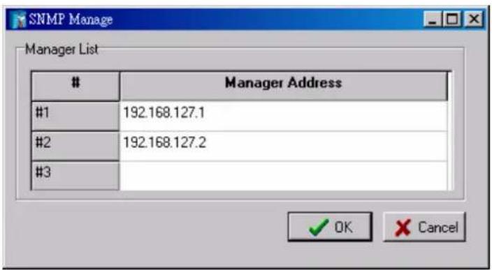
SNMP Trap Server
The ioLogik E2000 series provides SNMP v2 (Simple Network Management Protocol) to allow monitoring of the network and I/O devices with SNMP Network Management software. It is useful for building automation and telecom applications. When the system information of an ioLogik is required to be monitored, or a Click&Go logic is defined to update the I/O status via SNMP traps, one or up to 10 SNMP trap servers must be defined here.
E-Mail Server
The E-mail Server configures the parameters of the target e-mail servers and the recipient e-mail addresses. The Recipient Database should contain a list of available e-mail addresses for your network environment. The e-mail message defined in the Click&Go logic will be sent to all addresses listed in the Receiver(s) list. To add e-mail addresses to the Available receiver(s) list, enter the Name and Mail Address and click Add finger icons to move addresses to the Recipient Database; use the Remove finger icon to remove it.
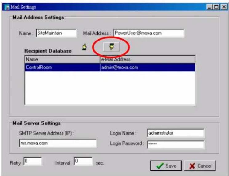
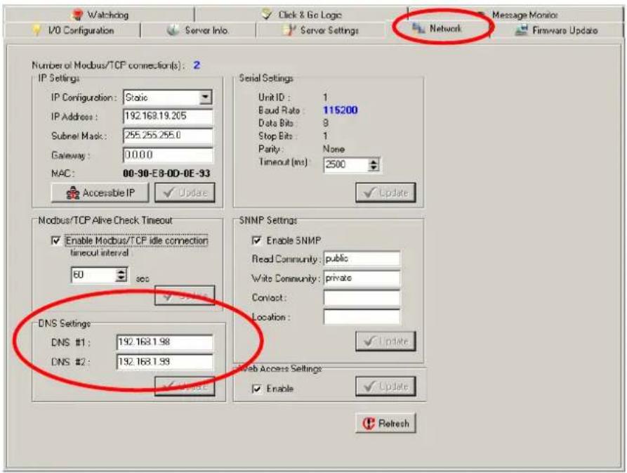
Under Mail Server Settings, you must configure the address of the SMTP server with your username and password. When using an FQDN (Fully Qualified Domain Name) address, such as ms.moxa.com, users must specify the DNS settings in the ioLogik.
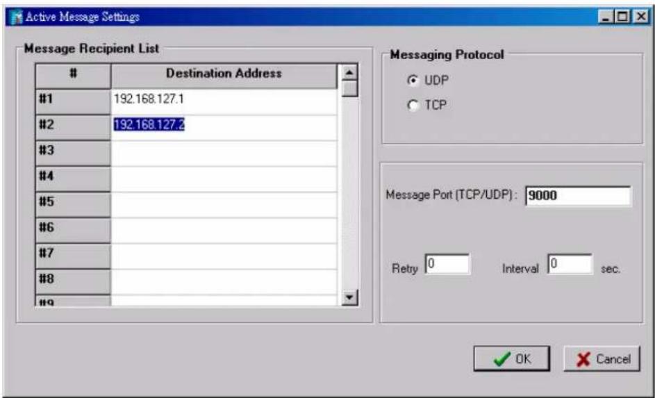
Active Message Server
The Active Message Server configures one or more destination IP addresses of the Message Servers that receive the event messages generated by the Click&Go logic. Message protocol (TCP or UDP) and the message socket port is also required to be configured here.
The active message defined in the Click&Go logic will be sent to all addresses listed in the Message Recipient List.
Work with Logic
Click&Go Logic Basics
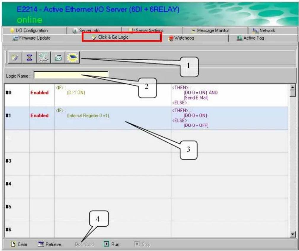
The Click&Go Logic tab is available after logging in as an administrator. This is where Click&Go logic is configured. With a set of rules (known as a rule-set) defined through Click&Go, the ioLogik can perform local and remote I/O control, report I/O status and actively send out messages, e-mails or SNMP traps to a host as soon as user-defined I/O conditions have been met.
To use Click&Go Logic, open ioAdmin and log in as an ioLogik administrator on the Server Settings tab. Once you are logged in, go to the Click&Go Logic tab. The following screen should appear:
| Click&Go Logic Tab |
| 1. Global Variables: In this field, you can configure the global variables of rules. |
| 2. Logic Name: In this field, you can assign a name for the set of rules. |
| 3. Rule-set: In this area, each rule's conditions, actions, and status are displayed. |
| 4. Rule-set Management Bar: In this area, you manage the rule-set. |
Rules are the building blocks of your ioLogik system. With rules, you define the exact trigger conditions for transmission of I/O information as well as the content and destination of that information.
Click&Go Logic can be defined with the following manners:
IF "A" THEN "B", ELSE "C"
For one control logic rule, there are three “A’s” that can be configured. “A” refers to the IF conditions that trigger an action. These three conditions can be operated by “AND” or “OR” logic. All three conditions must be all true to create the positive result if operating the conditions with “AND” logic. As for the “OR” logics, one or more true condition needs to trigger the action.
| A1 | A2 | A3 | Result of AND Logic | A1 | A2 | A3 | Result of OR Logic |
| 0 | 0 | 0 | 0 | 0 | 0 | 0 | 0 |
| 0 | 0 | 1 | 0 | 0 | 0 | 1 | 1 |
| 0 | 1 | 0 | 0 | 0 | 1 | 0 | 1 |
| 0 | 1 | 1 | 0 | 0 | 1 | 1 | 1 |
| 1 | 0 | 0 | 0 | 1 | 0 | 0 | 1 |
| 1 | 0 | 1 | 0 | 1 | 0 | 1 | 1 |
| 1 | 1 | 0 | 0 | 1 | 1 | 0 | 1 |
| 1 | 1 | 1 | 1 | 1 | 1 | 1 | 1 |
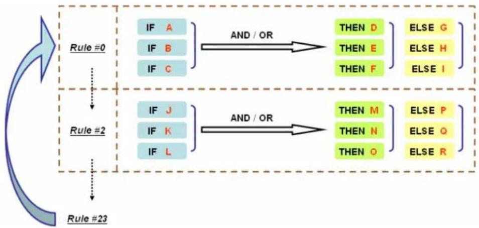
All 24 rules are defined individually and executed one by one in a loop. The 2^nd rule can only be processed after running the 1^st rule, and the entire rule-set will be start running over again from the beginning after the last rule is processed.

flowchart
graph TD
    A["Rule #0"] --> B["IF A"]
    A --> C["IF B"]
    A --> D["IF C"]
    B --> E["AND / OR"]
    C --> E
    D --> E
    E --> F["THEN D"]
    E --> G["THEN E"]
    E --> H["THEN F"]
    F --> I["ELSE G"]
    G --> J["ELSE H"]
    H --> K["ELSE I"]
    L["Rule #2"] --> M["IF J"]
    L --> N["IF K"]
    L --> O["IF L"]
    M --> P["AND / OR"]
    N --> P
    O --> P
    P --> Q["THEN M"]
    P --> R["THEN N"]
    P --> S["THEN O"]
    Q --> T["ELSE P"]
    R --> U["ELSE Q"]
    S --> V["ELSE R"]
    W["Rule #23"] --> X["AND / OR"]
    X --> Y["THEN M"]
    X --> Z["THEN N"]
    X --> AA["THEN O"]
    Y --> AB["ELSE P"]
    Z --> AC["ELSE Q"]
    AA --> AD["ELSE R"]
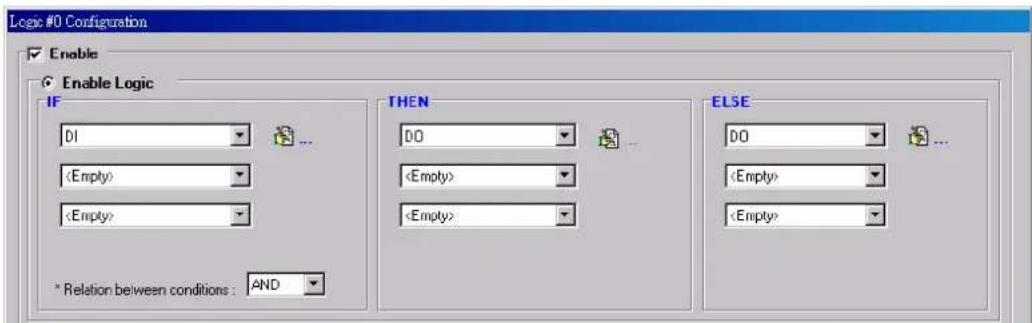
In the main screen, you will see a list of the rules in the current rule-set. Double Click on a rule to open that rule's configuration window shown as the following figure, or double click on an empty rule to start a new rule.
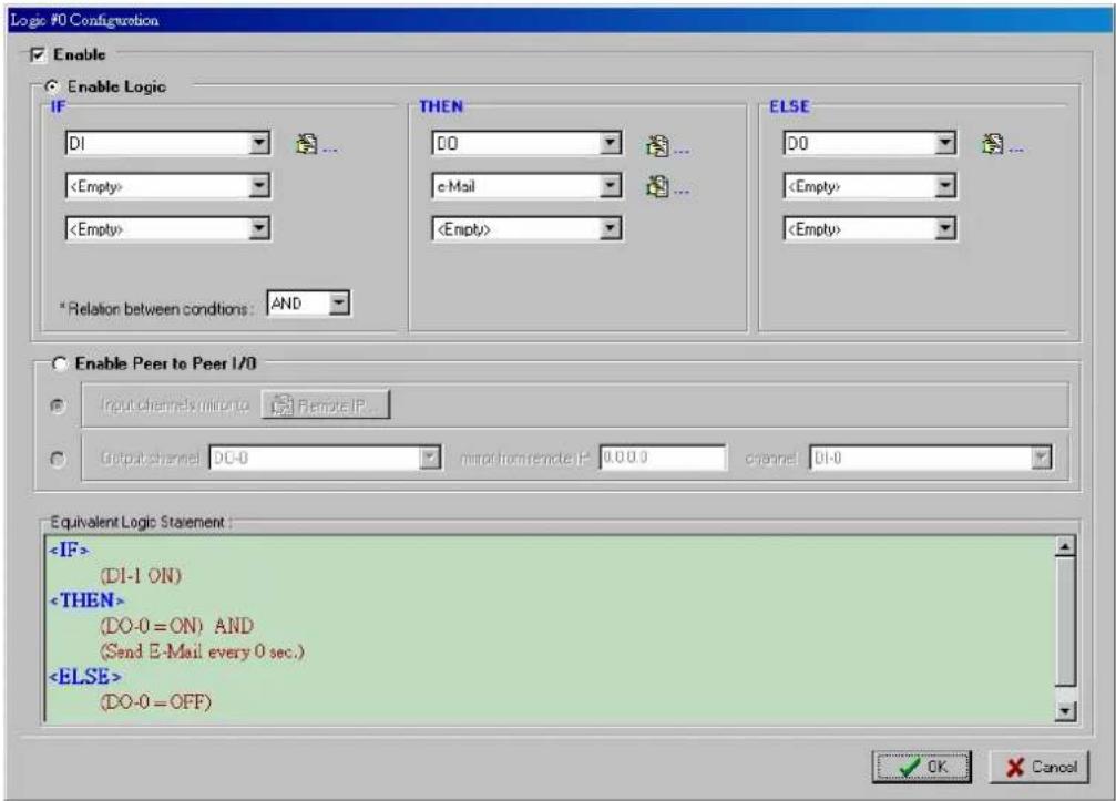
Under Relation between conditions, select AND to specify that all conditions must be satisfied for the actions to take place; select OR to specify that any one of the conditions can be satisfied for the actions to take place.
The configuration window is where the rule is defined. There are two types of rules that can be defined: Logic rules and peer-to-peer I/O rules. Logic rules are used for DI event-based triggers, whereas peer-to-peer I/O rules are used for mapping I/O channels between two ioLogik units.
The Equivalent Logic Statement at the bottom shows a real-time text-based summary of the rule that you are defining. It can be a useful way to make sure that the rule is designed as you intended.
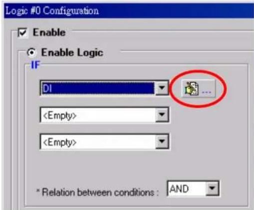
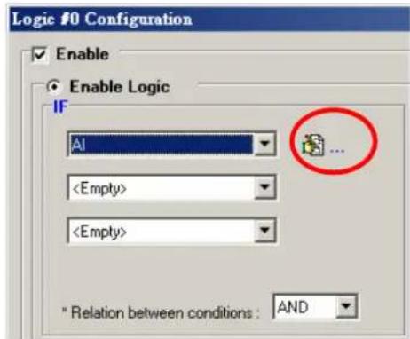
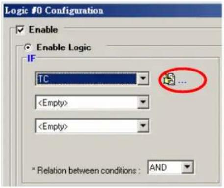
IF Conditions
IF conditions are events that trigger the THEN/ELSE actions. Under the IF column, you can set up to 3 conditions that must be satisfied for the actions under the THEN/ELSE column to take place. As soon as the IF conditions are satisfied, the specified THEN/ELSE action is performed. For example, an alarm can be activated when a door is opened. Use the pull downs to specify the conditions and units of measurement (e.g. DI-0=OFF).
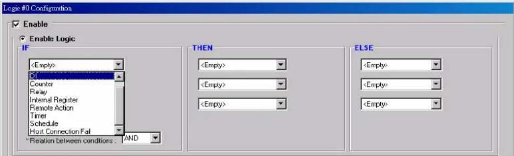
IF conditions can be specified as follows:
| IF Conditions Operators Remark | ||
| DI | ON, OFF, ON to OFF,OFF to ON, Change | DI-x represents the number of the channel. |
| Counter =, >, <, >=, <=, Change | Counter-x represents the number of the channel.Max Counter Value: 4,294,967,295 | |
| AI =, >, <, >=, <= | AI-x represents the number of the channel.Max Value: Depends on the analog Modes or the result of scaling | |
| RTD =, >, <, >=, <= | RTD-x represents the number of the channel.Max Value: Depends on the mode selection of RTD sensor | |
| TC =, >, <, >=, <= | TC-x represents the number of the channel.Max Value: Depends on the mode selection of TC sensor | |
| Relay =, >, <, >=, <= | CurRelayCNT-x represents the current relay counts of the channel.Max Value: 4,294,967,295 | |
| Internal Register = | Reg-x represents the number of the internal register.x = 00 to 23 / Trigger Value: 0 to 255 | |
| Remote Action | Received Action ID: 01 to 24Source IP Range:0.0.0.1 to 223.255.255.254 | |
| Timer | TIMEOUT | Timer-x, x = 00 to 23Max value: 4,294,967,295 seconds |
| Schedule Time, Range and Recurrence | ||
| Host Connection Fail | Modbus/TCP Idle Timeout.Max value: 3,600 seconds | |
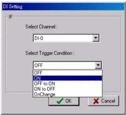
DI
DI refers to the status of a digital input channel. Edge detection can be used to refine the conditions. For example, the condition DI-0=OFF is satisfied for as long as DI-0 remains off. The condition DI-0=ON to OFF, however, is only satisfied the instant the DI-0 turns off. The transition of the status change can also be operated using the “Change” operator so it will trigger the related action whether it is ON-to-OFF or OFF-to-ON.
Select the IF condition to DI and click on the property ( ) button to enter the DI Settings window.
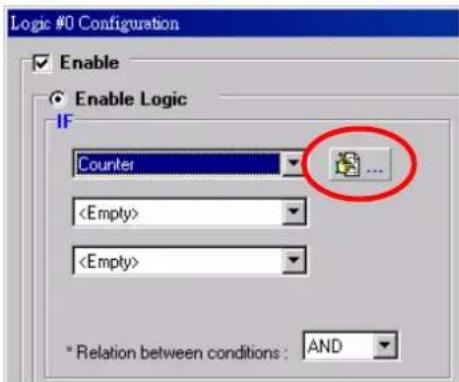
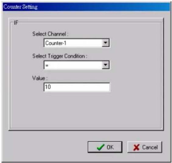
Counter
Counter refers to the counts of an Event Counter channel. The counts are stored in the ioLogik internally. Specifying the counts with a proper operator will lead to trigger the action. For example, 10 items should be packed in a box, so the Counter-x should be reset every 10 counts
(Counter-1=10). Select the IF condition to Counter and click on the property button ( ) to enter the Counter Settings window.
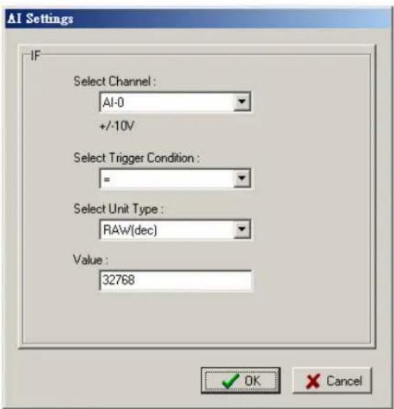
AI
AI refers to the readings of an analog input channel. Analog input value is specified to trigger an action. Units of the value are defined by the selected analog modes (voltage or current), or the scaling results. For example, AI-0 > 15mA represents the high level of a water tank.
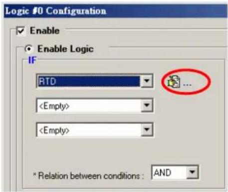
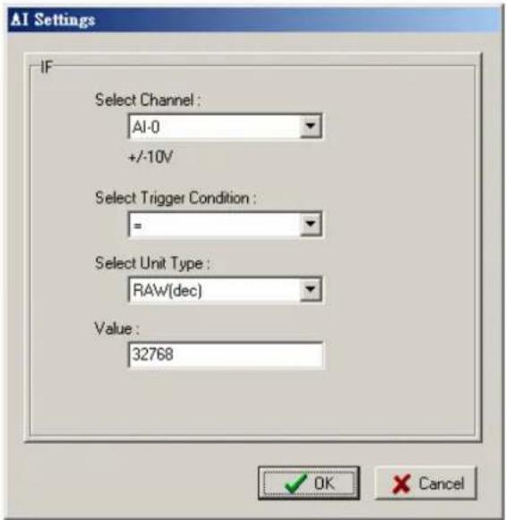
RTD
RTD refers to the readings of an RTD channel. RTD channels are used to measure temperature degrees. For example, an alarm should be triggered when the temperature reaches 40 degrees Celsius (RTD-0 > 40). Celsius or Fahrenheit temperature units can be selected in the I/O Configuration tab after logging in as an administrator.
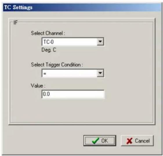
TC
TC refers to the readings of a TC channel. TC channels are used to measure temperature degrees. For example, an alarm should be triggered when the temperature reaches 500 degrees Celsius (RTD-0 > 40). Celsius or Fahrenheit temperature units can be selected in the I/O Configuration tab after logging in as an administrator.
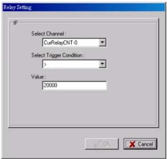
Relay (Counter)
Relay refers to the current counts of the relay usage. In ioLogik E2214, the counts of the relay usage is stored inside the ioLogik. Checking the current counts of a relay will produce the action. For example, the average life-cycle of a relay is 25,000 times. An alarm e-mail may be generated when the counter reaches 20,000 times (CurRelayCNT-0 > 20000) to report the need for replacement.
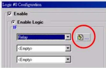
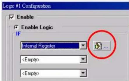
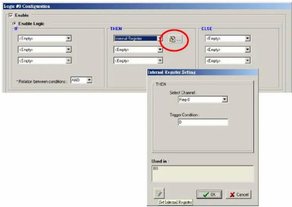
Internal Register
Internal Register represents a status flag to link the status of the first logic to the second one. Mostly it will be used with the Timer function or to combine other input statuses together. The Internal Register function also allows a PC to control the ioLogik's local output when the remote output is controlled by Click&Go log (e.g., digital output, active message, e-mail and SNMP Trap).
Select the IF condition for the Internal Register and click on the property button ( [icon: ] ) to enter the Set Internal Register window.

In the above figure, the "Used in:" column indicates that this Internal Register is also used in the Rule-0, which helps the user to identify the relationship between the rules. Also, the Set Internal
Register button ( ) will help to define the default value of all the Internal Registers.
NOTE
Internal Registers can be controlled by Modbus/TCP protocol. Refer to the appendix for the address list for all the Internal Registers.
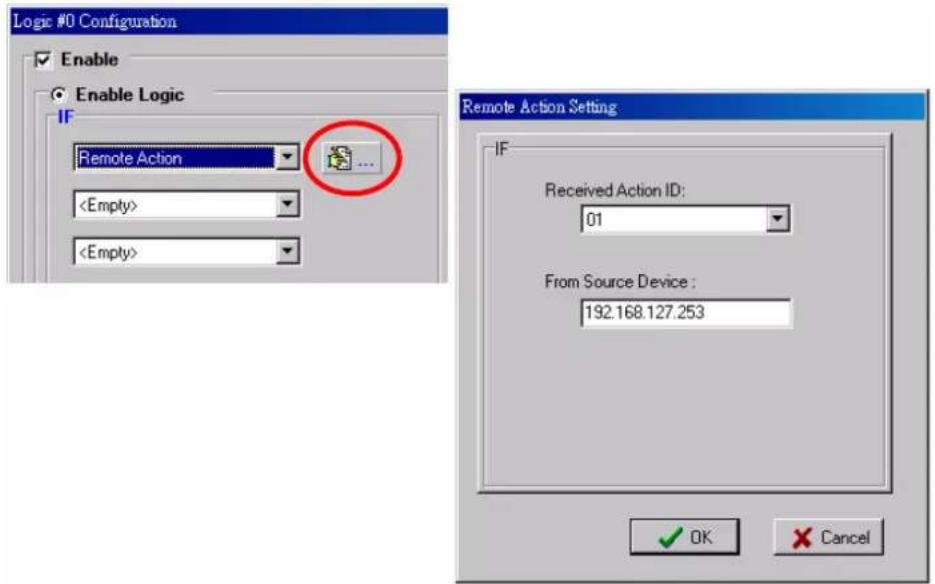
Remote Action
In the IF conditions, the Remote Action receives the command from one or more remote ioLogik. Specifying the ID and the source IP addresses can create an event. For example, a remote push button connected to an ioLogik can trigger a local siren. Select the IF condition for Remote Action and click on the property button ( ) to enter the Remote Action Settings window.
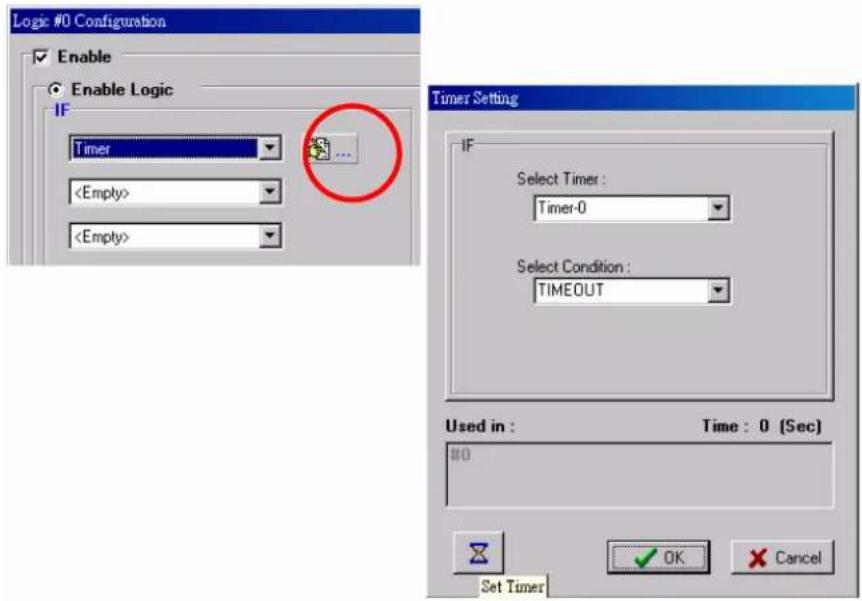
Timer
The Timer function can be used to control the timing of a logic rule in the IF conditions.
"TIMEOUT" is the only operator here. For example, uses can delay the triggering of an action or to repeat an action periodically. Select the IF condition for Timer and click on the property button

to enter the Timer Settings window.
In the above figure, the "Used in:" column indicates this Timer is also used in the Rule-0, which
helps the user to indentify the relationship between rules. Also the Set Timer button ( ) will help to define the default value for the Timer.
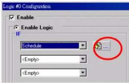
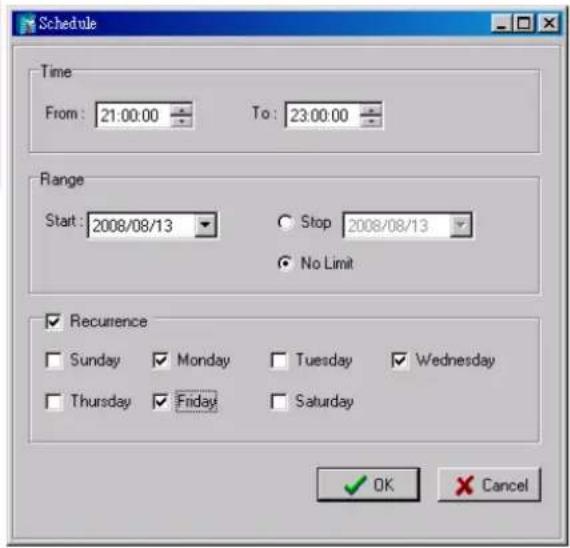
Schedule
The Schedule function allows users to set a starting point or time period for a task. For example, a pump needs to start at 9:00 PM and stop at 11:00 PM every Monday, Wednesday, and Friday.
Select the IF condition to Schedule and click on the property button ( ) to enter the setting window.
For recurrent actions, select the Recurrence checkbox and select the week days. If there a time period needs to be defined, specify the stop date in the range column.
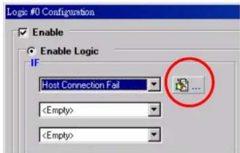
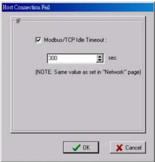
Host Connection Fail
The Host Connection Fail function refers to when an ioLogik detects the timeout from a remote Modbus/TCP host and directs it to one of the IF condition of the Click&Go logic. Timeout can be used to trigger an action such as resetting the attached power line on a DO or relay channel to reboot the device. Select the IF condition to Host Connection Fail and click on the property button

to enter the setting window.
More Info on Repeat Interval vs. Edge Detection
Combining the Timer function with other IF conditions allows actions to be repeated when the specified logic is sustained. However, if a condition is based on edge detection (i.e., ON to OFF or OFF to ON), it can only be triggered once.
The following scenarios illustrate how edge detection affects the Timer = N sec. In each diagram, the statuses of three sensors are shown over a period of time, with a high signal corresponding to a “true” condition. The green shaded area shows the duration of time that the IF conditions have been met.
| No Edge DetectionIn this scenario, the rule checks each sensor for “on” status, so edge detection is not involved. As long as the sensors remain on, the required conditions are satisfied, and the THEN actions will repeat at interval N. | ||
| DI-0 = ONDI-1 = ONDI-2 = ON | 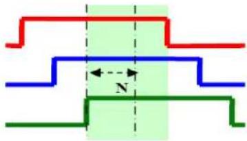 | 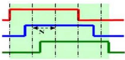 |
| Relation between conditions | AND | OR |
| “IF” conditions satisfied |  |  |
| Repeat interval | “Timer = N sec” | “Timer = N sec” |
| “THEN” action triggered |  |  |
| Edge Detection for All ConditionsIn this scenario, the rule checks each sensor for a change from “off” to “on” status, meaning only edge detection conditions are used. As soon as a sensor changes from “off” to “on”, the condition is satisfied, but only for that instant. Right after that instant, the condition is no longer satisfied because it is no longer changing from “off” to “on”. The repeat interval will have no effect, since edge conditions cannot be sustained over a period of time. | ||
| DI-0 = OFF to ONDI-1 = OFF to ONDI-2 = OFF to ON |  |  |
| Relation between conditions | AND | OR |
| “IF” conditions satisfied |  |  |
| Repeat interval | N/A | N/A |
| “THEN” action triggered |  |  |
Edge Detection for Two Conditions
In this scenario, the rule checks DI-0 and DI-1 for a change in status and DI-2 for status only. The repeat interval will not have an effect if the AND relationship is used, because the two edge conditions can never be sustained over a length of time. With the OR relationship, the IF conditions will be satisfied as long as DI-2 is “on”, and the THEN actions will be triggered over interval N.
| DI-0 = OFF to ONDI-1 = OFF to ONDI-2 = ON |  |  |
| Relation between conditions | AND | OR |
| “IF” conditions satisfied |  |  |
| Repeat interval | N/A | N/A |
| “THEN” action triggered |  |  |
Edge Detection for One Condition
In this scenario, the rule checks DI-0 for a change in status and DI-1 and DI-2 for status only. The repeat interval will not have an effect if the AND relationship is used, because the edge condition for DI-0 can never be sustained over a length of time. With the OR relationship, the IF conditions will be satisfied as long as DI-1 or DI-2 is “on”, and the THEN actions will be triggered over interval N.
| DI-0 = OFF to ONDI-1 = ONDI-2 = ON |  | 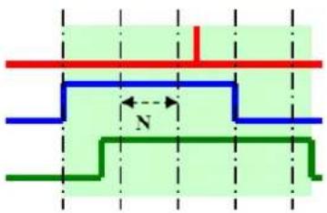 |
| Relation between conditions | AND | OR |
| “IF” conditions satisfied |  |  |
| Repeat interval | N/A | “Timer |
| “THEN” action triggered |  |  |
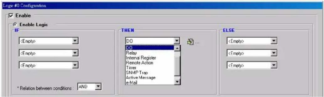
THEN/ELSE Actions
Under the THEN column, you can specify up to 3 actions that will be performed when the IF conditions are satisfied. 3 actions under the ELSE column will also be performed when the IF is NOT satisfied. Possible actions include changing the status of a DO channel, starting or stopping an Event Counter, or sending a message by SNMP trap, TCP, UDP, or e-mail.
| IF Conditions | Result of AND Logic | Trigger of THEN Actions | Trigger of ELSE Actions | ||
| A1 | A2 | A3 | |||
| 0 | 0 | 0 | 0 | No | YES |
| 0 | 0 | 1 | 0 | NO | YES |
| 0 | 1 | 0 | 0 | NO | YES |
| 0 | 1 | 1 | 0 | NO | YES |
| 1 | 0 | 0 | 0 | NO | YES |
| 1 | 0 | 1 | 0 | NO | YES |
| 1 | 1 | 0 | 0 | NO | YES |
| 1 | 1 | 1 | 1 | YES | NO |
| IF Conditions | Result of OR Logic | Trigger of THEN Actions | Trigger of ELSE Actions | ||
| A1 | A2 | A3 | |||
| 0 | 0 | 0 | 0 | NO | YES |
| 0 | 0 | 1 | 1 | YES | NO |
| 0 | 1 | 0 | 1 | YES | NO |
| 0 | 1 | 1 | 1 | YES | NO |
| 1 | 0 | 0 | 1 | YES | NO |
| 1 | 0 | 1 | 1 | YES | NO |
| 1 | 1 | 0 | 1 | YES | NO |
| 1 | 1 | 1 | 1 | YES | NO |
THEN/ELSE actions can be specified as follows:
| THEN/ELSE Actions Operators Remark | ||
| Counter | RESET | Counter-x represents the number of the Event Counter channel |
| DO | ON, | DO-x represents the number of the OFF channel. |
| Pulse Output STOP, START | Pulse Output-x represents the number of the channel | |
| AO | AO-x represents the number of the channel.Max Value: Depends on the analog Modes or the result of scaling | |
| Relay | RESET | ResetCNT-x represents the number of the relay channel. |
| Internal Register | Reg-x represents the number of the internal register.x = 00 to 23 / Trigger Value: 0 to 255 | |
| Remote Action | Action ID: 01 to 24Number of Remote IP Addresses: 5 sets | |
| Timer STOP, START, RESTART | Timer-x, x = 00 to 23Max value: 4,294,967,295 seconds | |
| SNMP Trap | I/O Status Bindings: 3 sets | |
| Active Message ID / Source IP Unicode supported | ||
| Create the contents of the e-Mail | ||
| CGI Command | ID / Source IP | Specify the target URL and CGI commands |
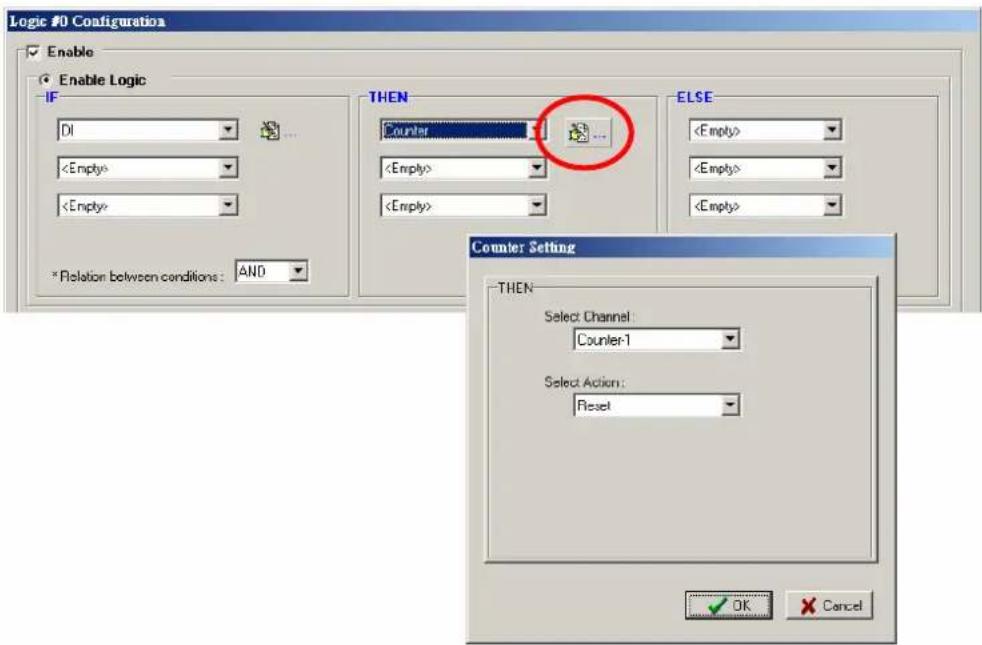
Counter
In this THEN/ELSE action, the only operator for the Counter function is “RESET”, which clears the counts of an Event Counter channel. This function is often used in a charging system to clear the readings of a meter. Select the THEN/ELSE action to Counter and click on the property button

to enter the Counter Settings window.
DO
DO refers to the action of controlling the local digital output channels that react to the IF conditions. Select the THEN/ELSE action to DO and click on the property button (☐) to enter the DO Settings window.
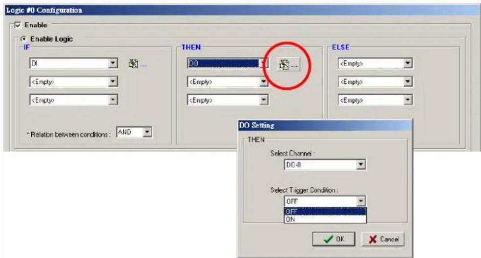
NOTE
A Relay output channel is also referred to as a DO channel in the THEN/ELSE action fields.
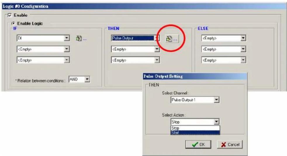
Pulse Output
Pulse Output starts or stops a pulse. It is usually used to create the flash for an alarm light. Select the THEN/ELSE action to Pulse Output and click on the property button ( ) to enter the Pulse Output Settings window.
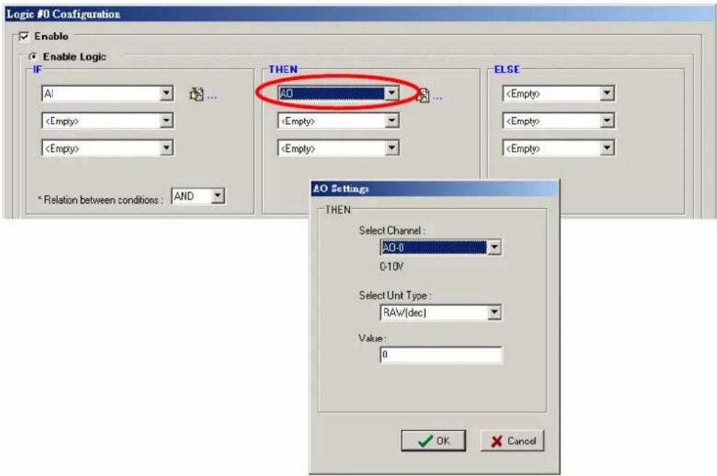
AO
AO refers to the local control of the analog output channels, including voltage and current. Analog output can be used to control the open angle of a valve of the movement of a solar panel.
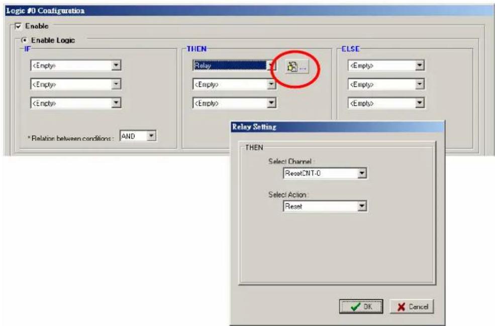
Relay (Counts)
In the THEN/ELSE action, Relay refers to the current counts specifying how many times a relay has been triggered. The counts are stored internally and can be cleared. "RESET" is the only
operator. Select the THEN/ELSE action to Relay and click on the property button ( ) to enter the Relay Settings window.
Internal Register
The Internal Register represents a status flag to link the status of the first logic to the second one by specifying other actions in the THEN/ELSE fields. Value from 0 to 255 can be configured here.
Select the THEN/ELSE action to Timer and click on the property button ( ) to enter the Internal Register Settings window.
In the above figure, the “Used in:” column indicates that this Internal Register is also used in the Rule-0, which helps the user to identify the relationship between the rules. Also the Set Internal
Register button (☐) will help to define the default value of the all the registers.
NOTE
Inter Register can be controlled by Modbus/TCP protocol, refer to the appendix for the address list for all the Internal Registers.
Remote Action
When responding to a proper IF condition, Remote Action in the THEN/ELSE action fields sends out a specific command ID to the remote ioLogik creating the remote IF condition. Select the THEN/ELSE action for Remote Action and click on the property button ( ) to enter the Remote Action Settings window.
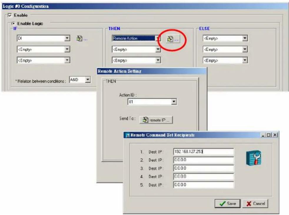
After specify the command ID, click on the Remote IP button to fill in the target ioLogik IP addresses.
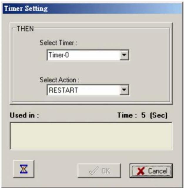
Timer
The Timer function can be used to control the time settings of a logic rule. Actions such as "START", STOP, and "RESTART" can be configured here.
Select the IF condition to Timer and click on the property button ( ) to enter the Timer Settings window.
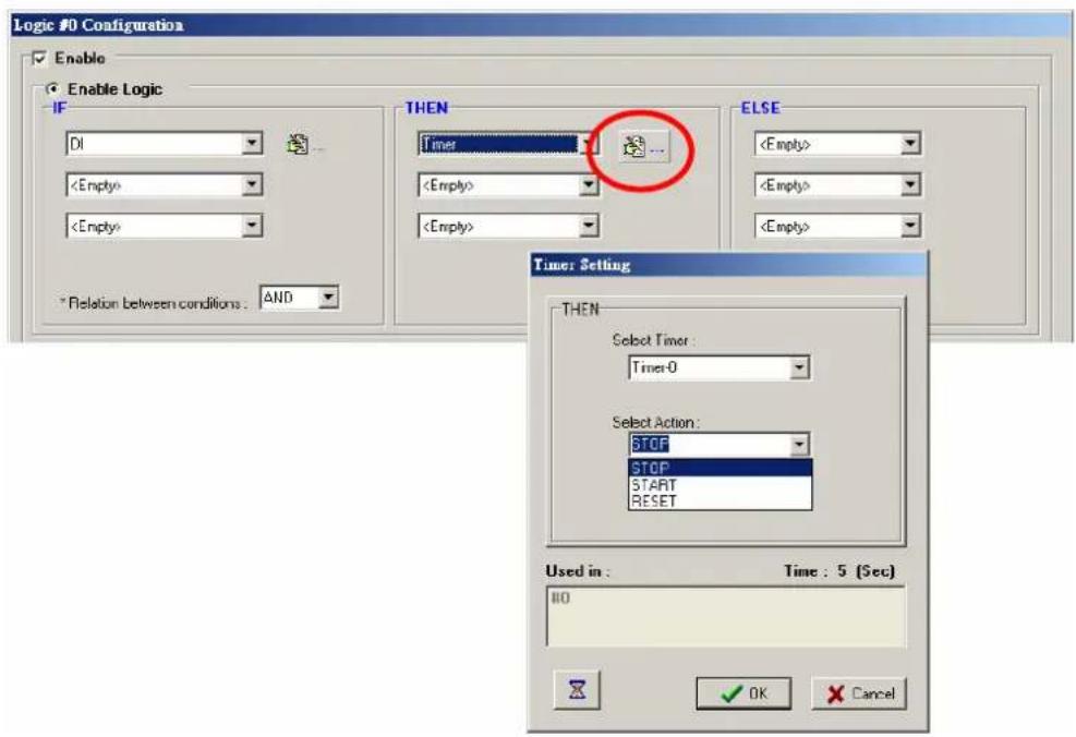
In the above figure, the "Used in:" column indicates this Timer is also used in the Rule-0, which
helps the user to identify the relationship between the rules. Also, the Set Timer button ( ) will help to define the default value for the Timer.
NOTE
While the "STOP" operator stops the timer and returns to "0", the "RESTART" operator clears and restarts the timer.

ATTENTION
The STOP or RESTART operator should always be used to reset or to restart the timer. Without using these operators, the Timer function can only be triggered once.
SNMP Trap
SNMP Trap function sends an SNMP trap to one or more IP destinations. You can select a trap number between 1 and 20. (You may need to consult with your network administrator to determine how trap numbers will be used and defined in your network.) Select the THEN/ELSE action to
SNMP Trap and click on the property button (…) to enter the SNMP Settings window. You can also bind the status of up to three I/O channels within each trap. Click the Set SNMP button

to specify up to 10 recipients for the SNMP trap.
![Logic #0 Configuration Enable Enable Logic IF DI ... * Relation: between conditions : AND THEN SNMP Trap ELSE SNMP Trap Setting Binding Variables Bind I/O channel status : [DI] 02 Bind I/O channel status : [DI] 00 Bind I/O channel status : [DI] 00 Select Specific ID : 1 * Sent every 0 sec. (0 = sent once) Set SNMP OK Cancel](/content/2026/06/1189123/images/980a3200d8d6a0938afd84ea4bfdd3073bdc6dcb6a145f883d7110fbacfe6292.jpg)
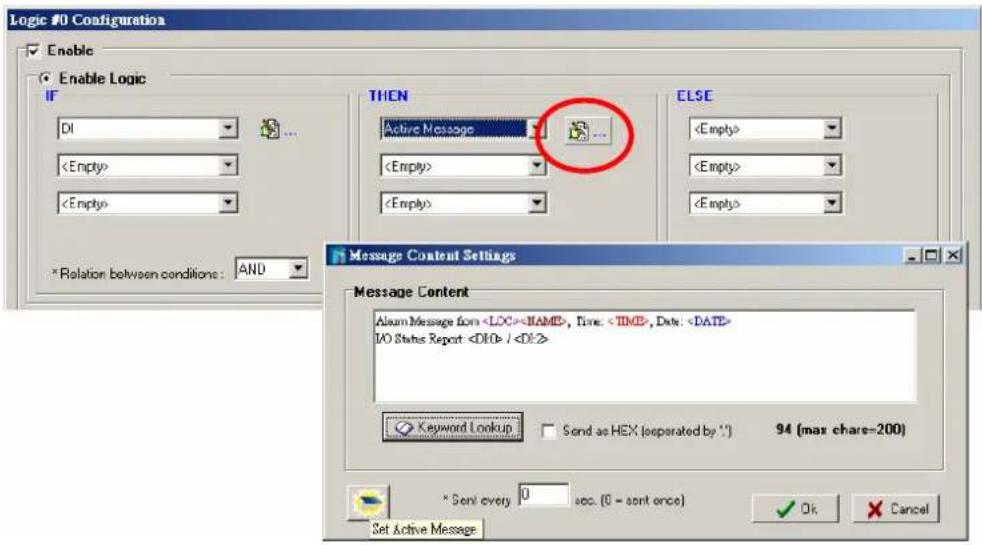
Active Message
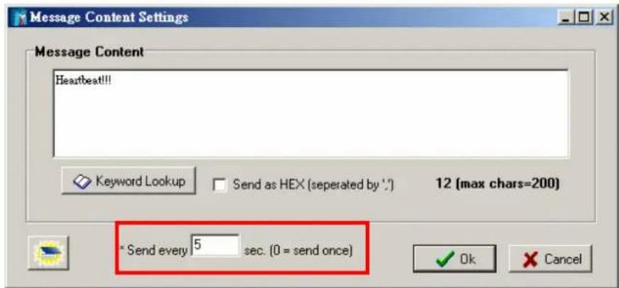
In response to a proper IF condition, the Active Message function sends a customized message to one or more IP destinations by TCP or UDP packets. Select the THEN/ELSE action to Active
Message and click on the property button ( ) to enter the Message Content Settings window. Enter your desired message in the Message Content column. Dynamic fields such as time, date, IP address, and I/O status can be inserted in your message by clicking Keyword Lookup. Messages are sent in ASCII by default, but can be sent in HEX by selecting "Send as HEX (separated by “;”)” checkbox.

Click the Set Active Message button (☐) to configure the default parameters such as the messaging protocol (TCP or UDP), socket port (9000 by default), and the up to 10 target message servers.
Active Messages can be received by a program using standard sockets, Moxa MXIO library, or ioAdmin's Message Monitor as in the following example:
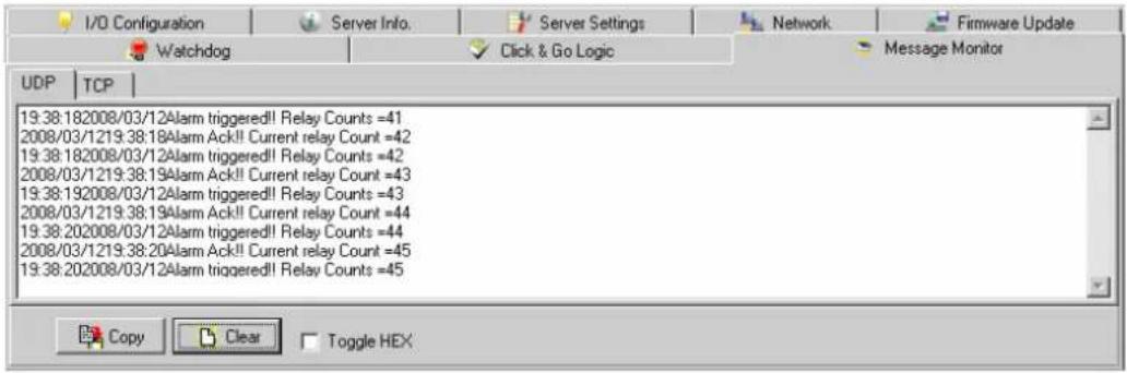
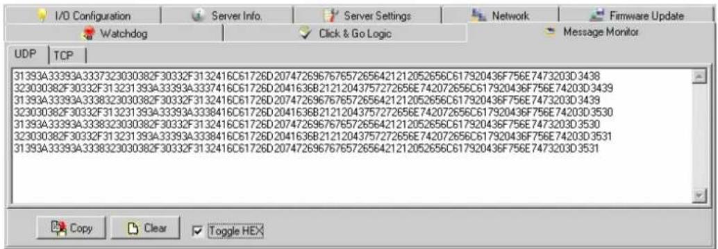
When sending a message in HEX, each HEX value must be delimited by commas. View the incoming message in the Message Monitor tab, select Toggle HEX checkbox. Note that certain numbers are control characters that will not show up in the Message Monitor, as shown in the following example:
The E-mail function sends a customizable e-mail to one or more mail boxes or Blackberrys. Select the THEN/ELSE action to e-mail and click on the property button ( ) to enter the Mail Settings window.
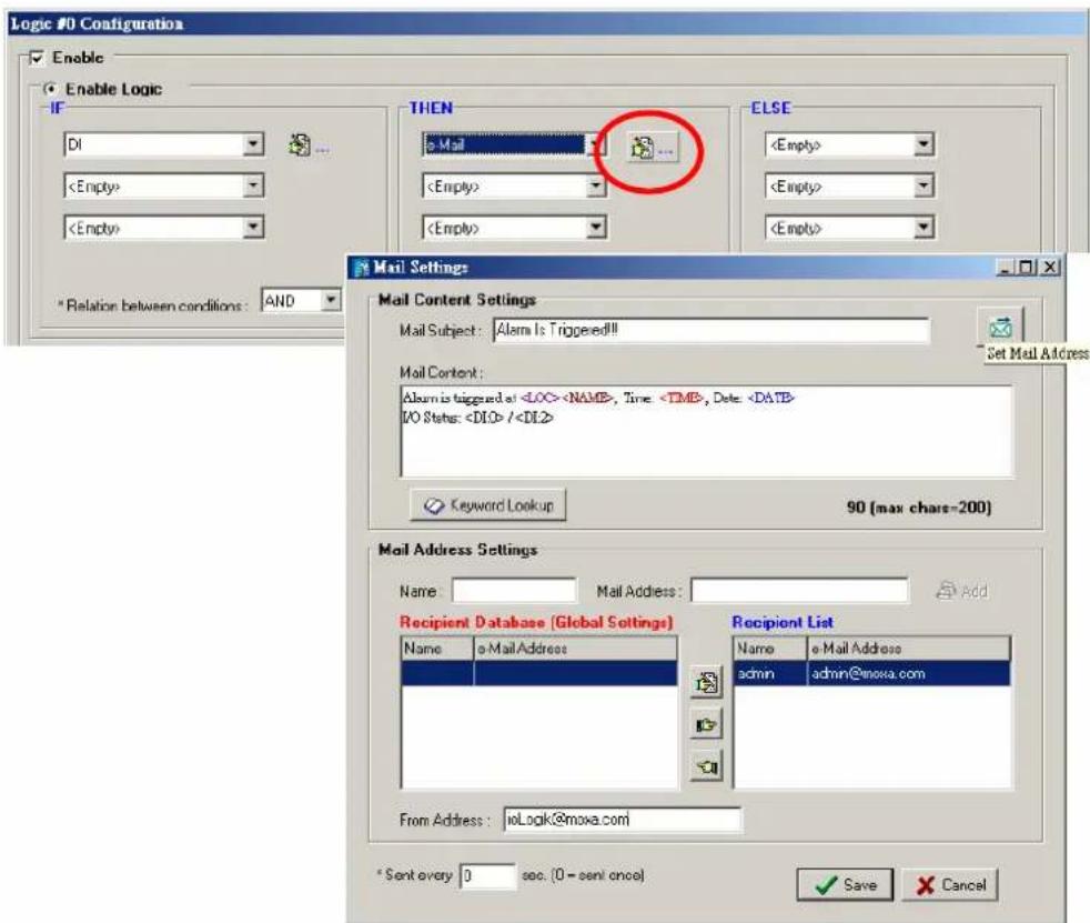
After entering the subject of an e-mail, enter the message in the Mail Content area. Dynamic fields such as time, date, IP address, and I/O status can be inserted in your message by clicking Keyword Lookup.
NOTE
Content in the same logic entry can be sent by either Active Message or e-mail, in which case the content of the messages will be the same. If you would like to send an Active Message and e-mail based on the same event but with different content, you will need to use two separate logic entries, one for the Active Message and one for the e-mail.
SMTP server information including username/password, and the recipient database can be
configured or by clicking the Set Mail Address button (____). Clicking the finger icon ( ) can move the selected address from the Recipient Database to the Recipient List.
To manually add e-mail addresses to the Recipient Database, enter the Name and Mail Address and click Add. Once the address has been added to the Recipient Database, use the finger icons to move it to or from the Recipient List.
CGI Command
Not only do the ioLogik products support CGI commands, they also allow the Click&Go logic to interact with proper IF conditions and send out CGI commands to IP Video devices such as the Moxa V351 video server or VPort 25 IP camera. Support for user-defined CGI commands in the Click&Go THEN/ELSE action turns the ioLogik product into the expansion I/O controller of these video devices. For example, setting a trigger to focus and take a snapshot when there is an intrusion. Select the THEN/ELSE actions for the CGI command and click on the property button

to enter the CGI Command Settings window.
![Logic #0 Configuration Enable Enable Logic IF DI * Relation between conditions : AND THEN CGI Command ELSE CGI Command Settings http:// 192.168.19.201 ControlPara/SNAP Port: 8d 16 (max chains=100) CGI Command: http://192.168.19.201:80/ControlPara/SNAP Trigger Setting " Send every 0 sec. (0 = send once) Retry 0 Interval 0 sec. (global) [global] OK Cancel IP or URL are allowed Customized Commands Column](/content/2026/06/1189123/images/272bb061c8406b518b3d136247fd21be8c0df70ccfb7085f58f37fe708f54f4a.jpg)
NOTE
In the first address column, IP address or URL can be used to specify the target. Only the DNS and Gateway settings of the ioLogik need to be specified.
Refer to the target IP video devices' user manual for detail CGI command formats.
Peer-to-Peer Function
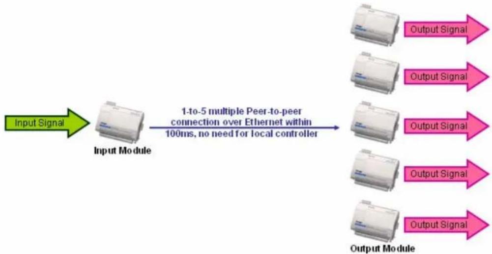
Peer-to-peer I/O is one of the Click&Go configurations besides the IF-THEN-ELSE logic. It can be used to set up I/O mapping over Ethernet from an input channel on one ioLogik to an output channel on another ioLogik. By using a pair of ioLogik products, the input status could be the trigger of a remote output. For example, if a push button is connected to DI channel 0 of ioLogik#1 and the Click&Go peer-to-peer I/O function is activated, the remote ioLogik#2 can turn its DO output channel on or off depending on the status of the remote ioLogik#1. Peer-to-peer I/O makes it easy to set up applications such as controlling a push button and lights located in different rooms, buildings, or even cities.
The ioLogik supports peer-to-peer I/O for simple one-to-one mapping as well as one-to-many and many-to-many mapping. A single input channel can trigger up to five remote output channels.
flowchart
graph LR
    A["Input Signal"] --> B["Input Module"]
    B --> C["1-to-5 multiple Peer-to-peer connection over Ethernet within 100ms, no need for local controller"]
    C --> D["Output Module"]
    D --> E["Output Signal"]
    D --> F["Output Signal"]
    D --> G["Output Signal"]
    D --> H["Output Signal"]
The peer-to-peer I/O function is configured in two steps. On the input module, a Click&Go Logic rule is defined to stream an input channel's signals to one or more output modules. On the output module, a Click&Go Logic rule is defined to receive an input module's input channel signals and mirror them on an output channel.
Configuring Input Module
The peer-to-peer I/O input module is configured using a single Click&Go rule. In the Click&Go tab, start a new rule, select Enable peer-to-peer I/O, and then select Input channels mirror to. Click Remote IP... and enter up to five IP addresses as destinations. Each IP address should belong to an ioLogik unit that will act as an output module for peer-to-peer I/O operation. You can also set up additional peer-to-peer I/O rules in order to mirror input channels to more than five destinations. If all 24 rules are used for peer-to-peer I/O, a total of 120 destination IP addresses can be entered.
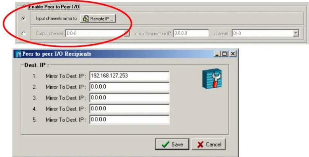
The ioLogik E2000 can simultaneously act as both an input module and an output module. Input module operation would be configured in one rule, and another rule would be used to configure output module operation.
| NOTE | Only DI channels that are set to DI mode can mirror remote DO channels. Event Counter channels cannot be used for peer-to-peer I/O operation. For analog input and output channels, they must be configured to the same voltage or current mode. Also, a digital channel can not mirror an analog output channel or vise versa. |
Configuring Output Module
The peer-to-peer I/O output module is configured using one Click&Go rule for each DO channel that is mirroring a remote input channel. In the Click&Go tab, start a new rule, select Enable peer-to-peer I/O, and then select Output channel. Specify the output channel that will mirror the remote input channel, the IP address of the input module, and the input channel on the input module whose signals will be mirrored. The input module must have specified the output module's IP address as a destination IP.
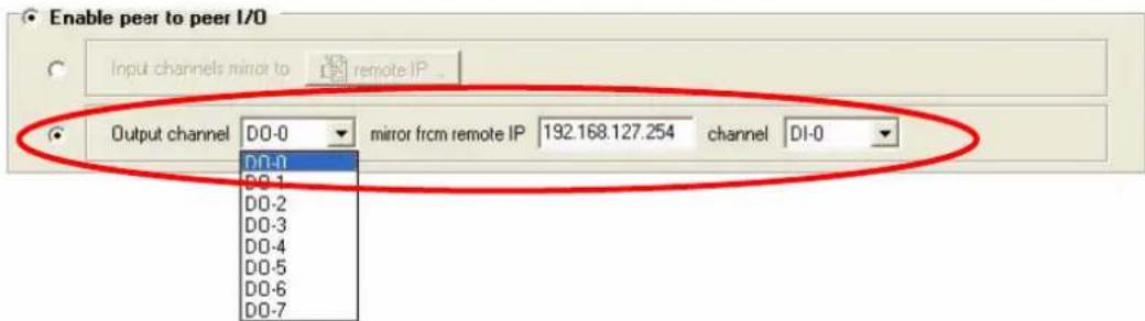
When properly configured, the specified output channel will mirror the signals received by the specified remote input channel, as if the channels were physically connected. For example, If the remote DI channel's status changes to "ON", the specified DO channel's status will change to "ON". If the remote DI channel's status changes to "OFF", the DO channel's status will change to "OFF".
Once both the input and output modules have been configured start peer-to-peer I/O operation by activating the rule-set on both units and providing a valid network connection to each unit.
| NOTE | Only DO channels that are set to DO mode can mirror remote DI channels. Pulse Output channels cannot be used for peer-to-peer I/O operation. For analog input and output channels, they must be configured to the same voltage or current mode. Also, a digital channel can not mirror an analog output channel or vise versa. |
Activating the Rule-set
Download, Restart and Run
In the Click&Go tab, the rules that are displayed in the Click&Go Logic tab comprise the current rule-set, which acts as the brain of your ioLogik system. The rule-set must be activated for the ioLogik to commence local control operation as follows:
-
The rule-set must first be downloaded from ioAdmin to the ioLogik. To download the rule-set, click Download from the Rule-set Management bar.
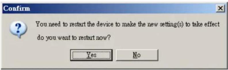
-
After the rule-set has been downloaded, ioAdmin will prompt to restart the ioLogik automatically after clicking "yes" to confirm. Do not use the reset button, as that will load all factory defaults and erase your rule-set from memory.
- After the ioLogik has been restarted, the rule-set must be activated. After logging into ioAdmin as an administrator, go to the Click&Go Logic tab and click Run in the Rule-set Management bar. The rules in the rule-set will now be active.
When the rule-set has been activated, it will remain active even when the ioLogik is disconnected from the host computer or from the network. If the ioLogik is turned off, Active Ethernet I/O operation will resume when it is turned back on. This allows you to use the ioLogik E2000 for PC-independent automation.
Rule-set Management Bar
In the Click&Go tab, When the rule-set has been activated, it will remain active even when the ioLogik is disconnected from the host computer or from the network. If the ioLogik is turned off, Active Ethernet I/O operation will resume when it is turned back on. This allows you to use the ioLogik E2000 for PC-independent automation.

- Clear: This erases the rule-set in both ioAdmin and the ioLogik E2000 series.
- Retrieve: This copies the rule-set from the ioLogik E2000 series into ioAdmin.
- Download: This copies the rule-set from ioAdmin onto the ioLogik E2000 series.
- Run: This activates the rule-set that the ioLogik booted up with.
- Stop: This de-activates the Click&Go rule-set and returns the ioLogik to normal, passive operation.
Import/Export Configuration
The ioLogik's system configuration can be imported and exported. This configuration includes the current Click&Go rule-set. As you make changes to a rule-set, you can export the system configuration in order to save that rule-set.
The Server Settings tab is where you log in as an ioAdmin administrator. This is required in order to gain access to the ioLogik configuration options. If no password has been set up, simply click Login and leave the Password for entry field blank.
Using ioAdmin to Import/Export Configuration
Export System Configuration
In the Navigation Panel, right click on the selected ioLogik and select the command "Export System Config" to export the configuration to a text file. You will need to be logged in as an administrator to use this command. It is strongly recommended you use this method to back up your configuration after you have finished configuring the ioLogik for your application.
![MOXA ioAdmin File System Sort Help Host : [192.168.19.201] ioLogik E2214 IP 192.168.19.205 E2214 - Active Ethernet I/O Server online Connect Disconnect Delete I/O Server Add Serial I/O Server Restart System Reset to Default Import System Config Export System Config Duration Server Info Server Settings of Modbus/TCP connection(s) : 2 ings Configuration: Static address: 192.168.19.205 Internet Mask: 255.255.255.0 eway: 0.0.0.0 C: 00-90-E8-14-DE-51 Accessible IP Update](/content/2026/06/1189123/images/e527bb7e0ce882ab4404acc3373464b456c8cdd071645e21f17ef2bcc9ec95e3.jpg)
The following is a sample configuration file:
iologik E2214 Network I/O Server Configuration
Date: 1970/01/-9525
Time: -2:-31:-2
Firmware: U1.0 Build08022212
[1. Model]
MOD_TYPE=E2214 - Active Ethernet I/O Server (6DI + 6DO)
MOD_LOC-
MOD_NAME=
[2. I/O Configurations]
DI00=0,(DI), DI00_FILTER=100,(150000.00ms)
DI01=0,(DI), DI01_FILTER=100,(150000.00ms)
DI02=0,(DI), DI02_FILTER=100,(150000.00ms)
DI03=0,(DI), DI03_FILTER=100,(150000.00ms)
DI04=0,(DI), DI04_FILTER=100,(150000.00ms)
DI05=0,(DI), DI05_FILTER=100,(150000.00ms)
DO00-0,(DO), DO00_PWM-1,(On), DO00_PVSEQ-0,(Sec),
DO01=0,(DO), DO01_PWM-1,(On), DO01_PVSEQ-0,(Sec),
DO02=0,(DO), DO02_PWM-1,(On), DO02_PVSEQ-0,(Sec),
DO03=0,(DO), DO03_PWM-1,(On), DO03_PVSEQ-0,(Sec),
DO04=0,(DO), DO04_PWM-1,(On), DO04_PVSEQ-0,(Sec),
DO05=0,(DO), DO05_PWM-1,(On), DO05_PVSEQ-0,(Sec),
[3. Modbus address table]
CHANNEL I/O TYPE NODBUS REFERENCE MODBUS ADDRESS (Dec, Hex)
DI00 Input 10001 8888, 8x8888
DI01 Input 18882 8881, 8x8881
DI02 Input 18883 8882, 8x8882
DI03 Input 18884 8883, 8x8883
DI04 Input 18885 8884, 8x8884
DI05 Input 18886 8885, 8x8885
Import System Configuration
In the Navigation Panel, right click on the selected ioLogik and select the command "Import System Config" to load a configuration for the selected ioLogik from a configuration text file. You will need to be logged in as an administrator to use this command. The new configuration will not take effect until the ioLogik has been restarted. This command can be used to restore a configuration after loading the factory defaults, or to duplicate a configuration to multiple ioLogik units.
![MOXA ioAdmin File System Sort Help Host : [192.168.19.201] ioLogik E2214 192.168.19.205 E2214 - Active Ethernet I/O Server online Connect Disconnect Delete I/O Server Add Serial I/O Server Restart System Reset to Default Import System Config Export System Config Configuration Server Info. Server Settings of Modbus/TCP connection(s) : 2 ings Configuration : Static Address : 192.168.19.205 Internet Mask : 255.255.255.0 teway : 0.0.0.0 C : 00-90-E8-14-DE-51 Accessible IP Update](/content/2026/06/1189123/images/9f7f328e3d9289e8c788bd4fbd0a841637441cbe1679a4c5eea0a61bc58f7647.jpg)
Using TFTP to Import/Export Configuration
TFTP (Trivial File Transfer Protocol) was defined in 1980 to provide basic FTP functionality in a very simple protocol. Due to TFTP's simplicity, it can be implemented using a very small amount of memory, an important consideration when it was first developed. ioLogik products support the use of TFTP to import or export configuration files.
The following is an example using Windows TFTP and an ioLogik E2212 with an IP address of 192.168.127.254:
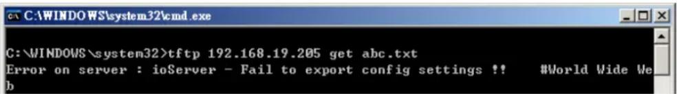
- Enter "TFTP 192.168.127.254 GET ik2212.txt to get the ioLogik's configuration file.
- Enter "TFTP 192.168.127.254 PUT ik2212.txt to load a configuration file onto the ioLogik
You must use "ik2212.txt" as the destination filename when copying a configuration file to the ioLogik E2212 unit. Otherwise, you will receive an error message as shown below:
You can use TFTP in a batch file to transfer configuration files for different units. For example, you might have two configuration files that need to be copied to two different servers: ik2212_1.txt for 192.168.127.253, and ik2212_2.txt for 192.168.127.254. A batch file could be written as follows:
tftp 192.168.127.253 put ik2212_1.txt ik2212.txt
tftp 192.168.127.254 put ik2212_2.txt ik2212.txt

ATTENTION
The name of the configuration files should always be specified as “ikxxxx” where xxxx is the ioLogik models. For example, to export the configuration file of an ioLogik E2242, the file must be “ik2242.txt” or ”ik2242_1.txt”.
In this chapter, examples and the typical applications is explained to show how to create an alarm system with Click&Go V2 local control logic with your ioLogik system.
The following topics are covered in this chapter:
□ Click&Go Rule 101
IF-THEN-ELSE
Where there is an ON Logic, there should be an OFF Logic
▶ Rules are Running in a Loop
□ Using the Timer Function
▶ Heartbeat or Repeat Actions
ON-Delay
OFF-Delay
□ Using Internal Registers
▶ Soft-key
Remote Control
□ Programming Examples
➢ Local I/O Control
Active I/O Messages
➢ Peer-to-Peer I/O
□ Applications\_1
□ Applications\_2
□ Applications\_3
□ Applications\_4
□ Applications\_5
□ Applications\_6
□ Applications\_7
Click&Go Rule 101
IF-THEN-ELSE
"Program in the way you think" is the number one rule in Click&Go programming. Just remember that if the IF conditions sustain, THEN actions will be triggered. If the IF conditions do not sustain, ELSE actions will be triggered.
IF "A" THEN "B", ELSE "C"
Where there is an ON Logic, there should be an OFF Logic
No matter what kind of action is triggered, remember to disable it. For example, when turning on an alarm light attached to a DO channel according to an event, there must be another event or input status to turn it off. Sometimes the OFF logic can be performed by using the ELSE actions.
IF DI_0=ON THEN DO_0=ON, ELSE DO_0=OFF
Rules are Running in a Loop
The complete list of 24 rules run in a loop. After the last rule, Click&Go will start over and begin running from the first rule. Be sure check your rules to avoid any conflict.
flowchart
graph TD
    A["Rule #0"] --> B["IF A"]
    A --> C["IF B"]
    A --> D["IF C"]
    B --> E["AND / OR"]
    C --> E
    D --> E
    E --> F["THEN D"]
    E --> G["THEN E"]
    E --> H["THEN F"]
    F --> I["ELSE G"]
    G --> J["ELSE H"]
    H --> K["ELSE I"]
    L["Rule #2"] --> M["IF J"]
    L --> N["IF K"]
    L --> O["IF L"]
    M --> P["AND / OR"]
    N --> P
    O --> P
    P --> Q["THEN M"]
    P --> R["THEN N"]
    P --> S["THEN O"]
    Q --> T["ELSE P"]
    R --> U["ELSE Q"]
    S --> V["ELSE R"]
    W["Rule #23"] --> X["AND / OR"]
    X --> Y["THEN M"]
    X --> Z["THEN N"]
    X --> AA["THEN O"]
    Y --> AB["ELSE P"]
    Z --> AC["ELSE Q"]
    AA --> AD["ELSE R"]
Using the Timer Function
Heartbeat or Repeat Actions
The Timer function can be used to generate non-stop repeating actions, such as heartbeat, by setting the Global Variable – Timer Settings to “START” and the THEN/ELSE action to “RESTART.”
A heartbeat TCP message can be generated using the following example.
| #0 | Enabled | : (Timer-0 TIMEOUT) : (Send Active Message) AND (Timer-0 RE START) |
The RESTART operator of the Timer function only restarts from the beginning. It does not stop timing.

ATTENTION
STOP or RESTART operator should always be used to reset or to restart the timer. If these operators are not used, the Timer function can only be triggered once.
For Active Messaging, e-mail, and SNMP trap THEN/ELSE actions, they are also capable of repeating their own function by selecting "Send Every ____ Sec." in the Message Content Settings.
The above example of sending periodically heartbeat Active Message can also be done as this way:
| #0 | Enabled | : (TIMER-0 TIMEOUT) | : (Send Active Message) |
Care must be taken while using the above pattern so that sending Active Messages, e-mails, or SNMP traps every x seconds is only generated when the IF condition sustains. Repeated actions or heartbeat messages do not sustain when the IF condition no longer exists.
For example, the ON status of a digital input is responsible for generating a non-stop message. Click&Go will stop sending messages when the DI=OFF.
ON-Delay
The ON-delay application sets a time period for the IF conditions to meet before the THEN action is executed. For example, to prevent a false alarm from shocks or stirring, a liquid sensor must reach the high limit for more than 15 seconds before triggering the alarm.
| #0 | Enabled | : (Timer-0 START) : | |
| #1 | Enabled | : (DO-1 = ON) |
OFF-Delay
Conversely, OFF-Delay keeps the action on running for a period of time from when the IF function is triggered to when the THEN action is executed. For example, after pushing a button to switch off the light in a lobby, the light stays ON for an additional 10 seconds before turning OFF so that the user can have enough time to walk out of the building.
| #0 | Enabled | : (DI-1 ON) | |
| #1 | Enabled | : (DI-1 OFF) | |
| #2 | Enabled | : (TIMER-0 TIMEOUT) |
Using Internal Registers
Soft-key
The Internal Registers can be used to ensure that the output is under control. For example, an output can only be triggered when the local push button is attached to a digital input and the internal register is set.
| #0 | Enabled |
In this example, the logic between the two IF conditions is "AND."
Remote Control
If an output channel is coordinated by an IF condition, it is limited to the Click&Go logic and can not be controlled by a remote PC. Users must use Internal Registers to set local and remote control for a designated output channel. For example, an emergency alarm siren is triggered remotely by a SCADA system when detecting high pressure or leaks. If the network is down, a local shutdown button can also be switched ON to sound the alarm.
| #0 | Enabled |
In this example, the logic between the two IF conditions is "OR".
| NOTE | Inter Register can be controlled by Modbus/TCP protocol, refer to the appendix for the addressed list for all the Internal Registers. |
Programming Examples
Local I/O Control
In this scenario, we planned to trigger the DO from local DI on the ioLogik.
Product Model: ioLogik E2210, E2212 or E2214.
Rule 0: IF DI-0=ON, THEN DO-0=ON, ELSE DO-0=OFF
| #0 | Enabled | : (DI-0 ON) |
- In ioAdmin, make sure you have logged in on the Server Settings tab. Go to the Click&Go Logic tab.
- Double click #0 in the Rule-set. The rule configuration window will appear.
- Make sure that Enable in the upper left hand corner is checked.
- Select Enable Logic.
- Select DI-0 as your condition in the first IF field, and set its value to ON.
- Select DO-0 as your action in the first THEN field, and set its value to ON.
- Select DO-0 as your action in the first ELSE field, and set it value to OFF.
- Click OK.
- Click Download on the Rule-set Management Bar.

-
Select Yes when asked to restart and wait until the ioLogik has restarted and is back on-line.
-
Click Run on the Rule-set Management Bar. The RDY LED will be flashing green, showing that the ioLogik is now operating as an Active Ethernet I/O server, using the rule-set that was just defined.

Active I/O Messages
In this scenario, we have a pressure sensor attached to the AI channel of the ioLogik; a DO channel is connected to a switch on an air pump. When the pressure of the tank is low, the ioLogik will start pumping. At the same time, the ioLogik will send a TCP message to the central office, indicating that the pump is ON. When pressure levels become high, the ioLogik will shut down the pump by turning off the DO. Another TCP message will then be sent as well. We want the ioLogik to send a TCP message that indicates the exact time the switch is turned on.
Product Model: ioLogik E2242
Rule 0: IF AI-0 <= 8 mA, THEN DO-6 = ON
THEN Active Message
Rule 1: IF AI-0 >= 18 mA, THEN DO-6 = OFF
THEN Active Message
| #0 | Enabled | : (AI-0 <= 8.000 mA, check every 0 sec) | : (DO-6 = ON) AND (Send Active Message) | |
| #1 | Enabled | : (AI-0 >= 18.000 mA, check every 0 sec) | : (DO-6 = OFF) AND (Send Active Message) |
- In ioAdmin, make sure that you have logged in on the Server Settings tab. Go to the I/O Configuration tab and set the AI-0 channel to 4-20 mA mode.
- Go to the Click&Go Logic tab. On the Global Variable tool bar, click on the Active Message Server button. Configure the Destination Address, Message Protocol, and Message Port. Click OK.
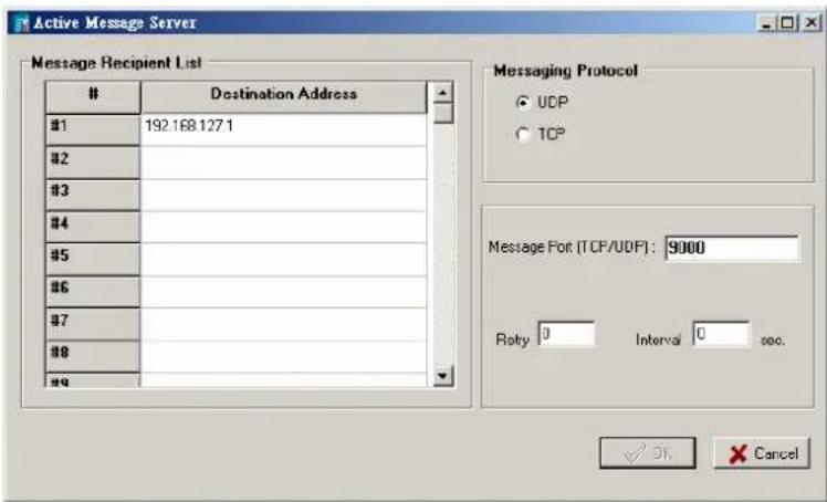
-
Double click #0 in the Rule-set. The Logic Configuration window will appear.
-
Make sure that Enable in the upper left hand corner is checked.
-
Select Enable Logic.
-
Select AI-0 as your condition in the first IF field, and set the operator to “<=”, value to “8” and the unit to “mA”.
-
Select DO-6 as your action in the first THEN field, and set its value to ON.
-
Select Active Message as your action in the second THEN field.
-
Click the property button. The Message parameters window will appear.
-
Click Keyword Lookup. In the Variable List that pops up, click
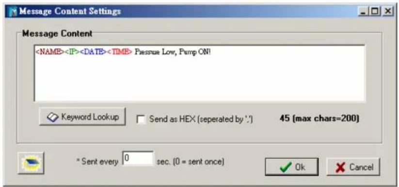
-
Click OK to close the Logic Configuration window.
-
Double click #1 in the Rule-set. The Logic Configuration window will appear.
-
Select AI-0 as your condition in the first IF field, and set its operator to “>=”, value to “18” and the unit to “mA”.
-
Select DO-0 as your action in the first THEN field, and set its value to OFF.
-
Select Active Message as your action in the second THEN field.
-
Click the property button. The Message parameters window will appear.
-
Click Keyword Lookup. In the Variable List that pops up, click
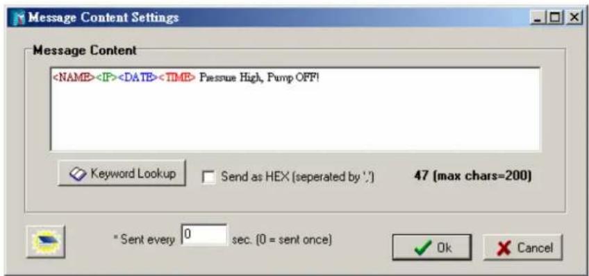
- Click OK to close the Logic Configuration window.
- Click Download on the Rule-set Management Bar.
- Select Yes when asked to restart and wait until the server has restarted and is back on-line.
- Click Run on the Rule-set Management Bar. The RDY LED will be flashing green, indicating the ioLogik is now operating as an Active Ethernet I/O server, using the rule-set that was just defined.
Peer-to-Peer I/O
The peer-to-peer I/O function operates as a mirror that converts and transmits I/O signals over long distances using Ethernet technology. One site of the ioLogik acts as an input and forwards the signal to an output site to avoid noise, extend the communication range, and redirect the signal to multiple destinations.

ATTENTION
Each ioLogik E2000 module is equipped with both input and output channels. Digital inputs can be forwarded only to digital outputs, and analog inputs can only be forwarded to analog outputs. Care must be taken while choosing the ioLogik models and the number of I/O channels.
Input Module (ioLogik E2242 192.168.127.154)
I/O Configuration:
The DIO-0 to DIO-5 is configured as a digital input and displayed as DI-0 to DI-5 in the Click&GO settings tab.
The DIO-6 to DIO-11 is configured as a digital output and displayed as DO-6 to DO-11 in the Click&GO settings tab.
Rule 0: Send I/O status to 192.168.127.3
-
In ioAdmin, make sure that you have searched for and selected the correct ioLogik E2242, at IP address 192.168.127.154. Also, make sure you are logged in on the Server Settings tab. Go to the Click&Go Logic tab.
-
Double click #0 in the Rule-set. The Logic Configuration window will appear.
-
Make sure that Enable in the upper left hand corner is checked.
-
Select Enable peer-to-peer I/O.
-
Select Input channels mirror to and click remote IP...
-
Select DI as the type to export the signal from the input module. In the 1. Dest. IP: field, enter 192.168.127.3 and click OK to save this setting.
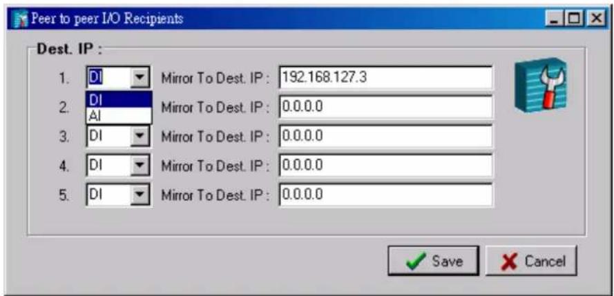
-
Click OK to close the Logic Configuration window.
-
Click Download on the Rule-set Management Bar.
-
Select Yes when asked to restart and wait until the server has restarted and is back on-line.
-
Log in on the Server Settings tab, then go to the Click&Go Logic tab.
-
Click Run on the Rule-set Management Bar. The RDY LED will be flashing green, showing that the ioLogik is now operating as an Active Ethernet I/O server, using the rule-set that was just defined.
Output Module (192.168.127.3)
Rule 0: DI-0 at 192.168.127.154 mapped to DO-0
Rule 1: DI-1 at 192.168.127.154 mapped to DO-1
-
In ioAdmin, make sure that you have searched for and selected the correct ioLogik E2242 server, at IP address 192.168.127.3. Also, make sure you are logged in on the Server Settings tab. Go to the Click&Go Logic tab.
-
Double click #0 in the Rule-set. The Logic Configuration window will appear.
-
Make sure that Enable in the upper left hand corner is checked.
-
Select Enable peer-to-peer I/O.
-
Select Output channel, then select DO-0 for the first field, enter 192.168.127.154 for the second field, and select DI-0 for the third field.

-
Click OK to close the Logic Configuration window.
-
Double click #1 in the Rule-set. The Logic Configuration window will appear.
-
Make sure that Enable in the upper left hand corner is checked.
-
Select Enable peer-to-peer I/O.
-
Select Output channel, then select DO-1 for the first field, enter 192.168.127.154 for the second field, and select DI-1 for the third field.

-
Click OK to close the Logic Configuration window.
-
Click Download on the Rule-set Management Bar.
-
Select Yes when asked to restart and wait until the server has restarted and is back on-line.
-
Click Run on the Rule-set Management Bar. The RDY LED will be flashing green, showing that the ioLogik is now operating as an Active Ethernet I/O server, using the rule-set that was just defined.
Applications\_1
The ioLogik E2260 provides temperature monitoring and alarm messaging for laboratories, hospitals, and blood banks.
Project Background
Laboratories, hospitals, and blood banks refrigerate their stocks of biochemical medicines, organic complexes, solutions, and blood at temperatures between 2 to 8°C to preserve quality. Constant monitoring is required to prevent vaporization, chemical change, or contamination. Therefore, alarm messages must notify staff immediately if any drastic change in temperature occurs.

natural_image
Interior view of a laboratory with white and blue equipment, no visible text or symbolsApplication Requirements
The existing network uses Ethernet SNMP (Simple Network Management Protocol) to gather necessary information such as network traffic and line status. Most of the I/O signal monitoring, such as temperature monitoring, runs on Modbus/TCP or other proprietary protocols that take time for IT engineers to learn. As a result, a temperature monitoring system for the freezers must be established in a short amount of time and use SNMP protocol.
Moxa Solution
The ioLogik E2260 Active Ethernet I/O server is designed for mixed I/O applications. The 6 RTD analog inputs are able to connect to 13 types of Pt (platinum) and Ni (nickel) sensors, in addition to 4 types of resistance measurement. The 4 embedded digital outputs are suitable for triggering a hard alarm locally. Most of all, the I/O status can be polled by the SNMP management software from the control center. The ioLogik also sends out SNMP traps to report the current status when the temperature becomes too high.
Solution Benefits
The ioLogik E2260 provided the freezer temperature monitoring system with the following benefits:
√ I/O status control and monitoring via SNMP saves development effort.
√ Automatic SNMP trap reports.
√ A controller with both RTD inputs and digital output channels
√ 16-bit high resolution measurement with more than 13 types of sensor connection
Click&Go's easy IF-THEN-ELSE style control logic, which eliminates the need for a PLC or RTU
√ Compact size and cost-effectiveness
Additional Features
The ioLogik E2260 is also equipped with the following features:
√ Local alarm output via digital channels
√ Alarm notifications via e-mail
√ Periodic status updates via SNMP trap
√ Moxa's Active OPC Server to connect ioLogik devices to the most popular SCADA systems
System Diagram
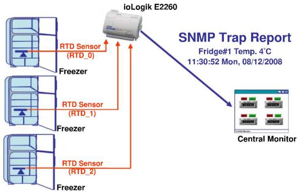
flowchart
graph TD
    A["ioloLogik E2260"] -->|RTD Sensor (RTD_0)| B["Central Monitor"]
    A -->|RTD Sensor (RTD_1)| B
    A -->|RTD Sensor (RTD_2)| B
    B --> C["SNMP Trap Report\nFridge#1 Temp. 4°C\n11:30:52 Mon, 08/12/2008"]
Click&Go Programming Example
I/O Alias and Mode Configuration
- Configure the RTD_0 channel to PT100 mode, set the alias name of this channel to Freezer#1
- Configure the RTD_1 channel to PT100 mode, set the alias name of this channel to Freezer#2
- Configure the RTD_2 channel to PT100 mode, set the alias name of this channel to Freezer#3
| Channel# | Sensor | Value | Range | Unit |
| [Freezer#1]:00 | PT100 | 0.0 | -200.0~850.0 | Deg. C |
| [Freezer#2]:01 | PT100 | 0.0 | -200.0~850.0 | Deg. C |
| [Freezer#3]:02 | PT100 | 0.0 | -200.0~850.0 | Deg. C |
Programming Manners
- Send a SNMP trap to report the temperature of the Freezer#1 when it reaches 8^ C.
- Send a SNMP trap to report the temperature of the Freezer#2 when it reaches 8°C.
- Send a SNMP trap to report the temperature of the Freezer#3 when it reaches 8°C.
Click&Go Rule-set
| #0 | Enabled | : (Send Vendor Specific SNMP Trap, ID=1) | |
| #1 | Enabled | : (Send Vendor Specific SNMP Trap, ID=2) | |
| #2 | Enabled | : (Send Vendor Specific SNMP Trap, ID=3) |
Applications\_2
The ioLogik E2262 provides temperature monitoring, alarm and shutdown control for a pumping system.
Project Background
In the pumping system of a tank farm, bearings of a pump motor always burn out after the motor runs non-stop for a period of time. The downtime and damage caused by overheated bearings raise maintenance costs and reduce output. Extra expenses are not only incurred from repairing or replacing the bearings, but paying the engineers for overtime as well.

natural_image
Industrial equipment setup with blue pipes and motors in a factory setting (no visible text or labels)Application Requirements
In order to keep the motors running smoothly and continuously, the tank farm requested a remote monitoring and control system to monitor the temperature of the motors. When the temperature rises too high, the front-end controller must shut down the motor and restart it after the temperature cools back down to an appropriate level. In addition, the front-end controller must send out a notification e-mail to the central site and field engineer's blackberry when the motors shut down and recover.
Moxa Solution
The ioLogik E2262 Active Ethernet I/O server is designed for mixed I/O applications. The 8 TC (thermocouple) inputs can connect 9 types of TC sensors (mV mode included) and the 4 built-in digital inputs can connect to multiple outputs such as alarms, buzzers, and lights. With the Click&Go local control logic, users can easily program the ioLogik E2262 to control the pumps, generate alarms, send status updates to the control center, or deliver e-mail notifications. Click&Go logic also allows the ioLogik to seamlessly integrate and manage temperature monitoring, output control, and alarms.
Solution Benefits
The ioLogik E2262 provided the pumping system with the following benefits:
√ A controller with both TC temperature sensor inputs and digital output channels
√ 100 meters of TC sensor cable length with 2 built-in CJC
√ Click&Go's easy IF-THEN-ELSE style control logic, which eliminates the need for a PLC or RTU
√ Alarm messaging can be generated via TCP, UDP, or SNMP trap, or e-mail
√ Compact size and cost-effectiveness
Additional Features
The ioLogik E2262 is also equipped with the following additional features:
√ Scheduling feature sets start and shutdown times for the pump motors
√ Moxa's Active OPC Server to connect ioLogik devices to the most popular SCADA systems
System Diagram
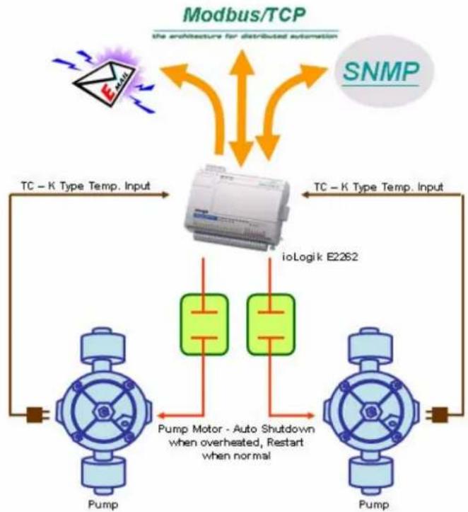
flowchart
graph TD
    A["Pump"] --> B["Modbus"]
    B --> C["SNMP"]
    D["Pump Motor - Auto Shutdown when overheated, Restart when normal"] --> E["ioLogik E2262"]
    E --> F["TC - K Type Temp. Input"]
    F --> G["TC - K Type Temp. Input"]
    G --> H["Modbus/TCP"]
    style A fill:#f9f,stroke:#333
    style D fill:#bbf,stroke:#333
    style B fill:#dfd,stroke:#333
    style E fill:#dfd,stroke:#333
    style F fill:#dfd,stroke:#333
    style G fill:#dfd,stroke:#333
Click&Go Programming Example
I/O Alias Configuration
- Temperature Input TC_0: 1 ^st Pump Motor Temperature Sensor.
- Temperature Input TC_1: 2^nd Pump Motor Temperature Sensor.
- Digital Output DO_0: 1 ^st Pump Motor Start/Shutdown Control.
- Digital Output DO_1: 2 ^nd Pump Motor Start/Shutdown Control.
I/O Mode Configuration
- Configure the TC Channels to the correct Mode, in this case, it is K-type sensors with calluses display; set the alias name for each channel.
- Configure the DO channel, set the alias name for each channel.
| Channel | Sensor | Value | Range | Unit |
| [P.Temp_0]:00 | K Type | -- | -200.0~1250.0 | Deg. C |
| [P.Temp_1]:01 | K Type | -- | -200.0~1250.0 | Deg. C |
| Channel | Mode | Status | Low | High |
| [Switch_0]:00 | DO | OFF | -- | -- |
| [Switch_1]:01 | DO | OFF | -- | -- |
Programming Manners
- 1 ^st pump motor shuts down when temperature rises to High (110°C), send out an alarm e-mail.
- 1 ^st pump motor restarts when temperature falls to Low (70°C), notify with an e-mail.
- 2 ^nd pump motor shuts down when temperature rises to High (110°C), send out an alarm e-mail.
- 2 ^nd pump motor restarts when temperature falls to Low (70°C), notify with an e-mail.
Click&Go Rule-set
| #0 | Enabled | : (P.Temp_0-0>=110.0 Deg.C, check every 0 sec) | : (Switch_0-0=OFF) AND (Send E-Mail) | ||
| #1 | Enabled | : (P.Temp_0-0<=70.0 Deg.C, check every 0 sec) | : (Switch_0-0=ON) AND (Send E-Mail) | ||
| #2 | Enabled | : (P.Temp_1-1>=110.0 Deg.C, check every 0 sec) | : (Switch_1-1=OFF) AND (Send E-Mail) | ||
| #3 | Enabled | : (P.Temp_1-1<=70.0 Deg.C, check every 0 sec) | : (Switch_1-1=ON) AND (Send E-Mail) |
Applications\_3
The ioLogik E2210 handles the alarm system of walk-in refrigerators in a semiconductor factory.
Project Background
A semiconductor factor preserves its stock of epoxy resin and silicon-based materials in large walk-in refrigerators at temperatures below 5°C. Temperatures higher than that will cause both the physical and chemical characteristics of the materials to change. This renders the materials unusable and lowers the factory's production. The temperature increases in the refrigerator are primarily due to the fact that the doors are not usually closed all the way when employees come in and out. As a result, an alarm system was requested by the semiconductor factory to monitor the refrigerator door.

natural_image
Interior view of a long, empty industrial facility hallway with stainless steel doors and ventilation systems (no visible text or symbols)Application Requirements
The system requested basically needs to monitor the opening and closing of the walk-in refrigerator door. It takes a factory worker an average of 1 minute to enter the refrigerator, locate the appropriate materials, and exit the refrigerator with the materials in hand. An alarm must be generated when the door remains open for over 1 minute. Due to the tight timeframe available for deploying the alarm system, engineers needed to find a quick solution that did not require extensive programming or complicated communication protocols. In addition to local control capabilities for the door sensor and alarm, the semiconductor factory also required a solution that would allow complete connectivity with a central PC or ERP/MES system.
Moxa Solution
The ioLogik E2210 Active Ethernet I/O server is designed for combination I/O applications. The 12 digital inputs can connect to different door sensors and switches and the 8 built-in digital outputs provide flexible connections to multiple alarm devices. Unlike programming a front-end PC or stand-alone PLC, the ioLogik's Click&Go control logic uses an easy to use IF-THEN-ELSE style of programming that doesn't require any compilers or debugging tools. The ioAdmin utility also allows users to configure the alarm system within 5 minutes with the click of a button. Moreover, the ioLogik E2210 provides both Ethernet connectivity and several ways to update status including e-mail warnings, TCP/UDP active messaging, SCADA/OPC connectivity, and SNMP trap I/O reports.
Solution Benefits
The ioLogik E2210 provided the semiconductor factory with the following benefits:
√ A controller equipped with both digital inputs and digital output channels
Click&Go's easy IF-THEN-ELSE style control logic, which eliminates the need for a PLC or RTU
√ Simultaneous control for local and remote Ethernet
√ Alarm messaging via TCP/UDP/SNMP trap or e-mail
√ Compact size and cost-effectiveness
Additional Features
The ioLogik E2210 is also equipped with the following features:
√ More local input functions such as local acknowledgement or open detection of the control box
√ Moxa's Active OPC Server to connect ioLogik devices to the most popular SCADA systems
System Diagram
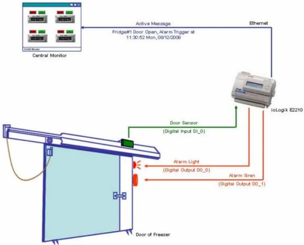
flowchart
graph TD
    A["Central Monitor"] -->|Active Message| B["IoLogik E2210"]
    B -->|Ethernet| C["Fridge#1 Door Open, Alarm Trigger at 11:30:52 Mon, 08/12/2008"]
    C --> D["Door Sensor (Digital Input D1_0)"]
    D --> E["Door of Freezer"]
    E --> F["Alarm Light (Digital Output D0_0)"]
    F --> G["Alarm Siren (Digital Output D0_1)"]
Click&Go Programming Example
I/O Alias and Timer Configuration
- Digital Input DI_0: Door-Sensor#1
- Digital Output DO_0: Alarm#1
| Channel | Mode | Status | Filter | Trigger |
| [Door_Sensor#1] | DI | OFF | 50.0 ms | -- |
| Channel | Mode | Status | Low | High |
| [Alarm Light#1]:00* | DO | OFF | -- | -- |
| [Alarm Siren#1]:01 | DO | OFF | -- | -- |
- Configure the default interval of Timer_0 to 60 seconds
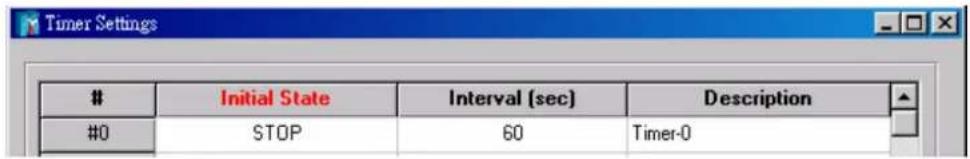
Programming Manners
- When the door is open, start the timer.
- When the timer times out after 60 seconds, trigger the alarm and send out an active message.
- Once the door is closed, disable the alarm and stop the timer.
Click&Go Rule-set
| #0 | Enabled | : (Timer-0 START) : (Timer-0 STOP) | |
| #1 | Enabled | : (Alarm Light#1-0 = ON) AND (Alarm Siren#1-1 = ON) AND (Send Active Message) | |
| #2 | Enabled | : (Alarm Light#1-0 = OFF) AND (Alarm Siren#1-1 = OFF) |
Applications\_4
The ioLogik E2242 handles control and alarms for a sump pump system.
Project Background
Many industries use a sump pit to collect wastewater from machines, cutting oil, and toxic solutions from the production line. When the level of the liquid in the sump pit reaches a certain level, the liquid in the sump pit must be pumped out to a holding tank. If the system is set up as an open-loop system, engineers must periodically check the level of the sump pit. They must manually turn the pump on when the sump pit is nearly full, and then turn the pump off when the sump pit is nearly empty.

natural_image
Interior view of a dimly lit room with exposed wooden beams and a metal support structure (no text or symbols visible)Application Requirements
A better method of sump pump control is to use a closed-loop central monitoring system such as a SCADA system. In this case, a sensor is connected to a controller to turn the pump on and off automatically. The sensor and control mechanism should be able to detect the liquid level and start or stop the pumping action when the float switch senses that the liquid level is too high or too low. Multiple pump control and alarm generation must also be included as part of the control system. Alarm indicators should be triggered when the pump starts or when the water reaches a high level. Moreover, the sump pump must be controlled either automatically or manually from a remote location.
Moxa Solution
The ioLogik E2242 is an Active Ethernet I/O server designed for mixed I/O applications. The 4 analog inputs are able to connect to liquid level sensors based on either voltage or electric current, and the 12 built-in configurable DIOs provide the best flexibility for connecting to multiple input switches or triggering pumps and alarms. With the user-friendly Click&Go local control logic, users can easily program the ioLogik E2242 to act as a front-end pump controller and alarm generator to control automatically the action of the pumps, generate alarms, and send the most up-to-date status to the central SCADA system, or by e-mail to the field engineers.
Solution Benefits
Moxa's ioLogik E2242 provided the sump pump control system with the following benefits:
Click&Go's easy IF-THEN-ELSE style control logic, which eliminates the need for a PLC or RTU
√ Active reports via TCP/UDP/SNMP trap, and e-mail
√ Relay count reports
√ Compact size and cost-effectiveness
Additional Features
The ioLogik E2242 is also equipped with the following features:
√ Scheduling function to set when to pump the wastewater
√ Moxa's Active OPC Server to connect ioLogik devices to the most popular SCADA systems
System Diagram
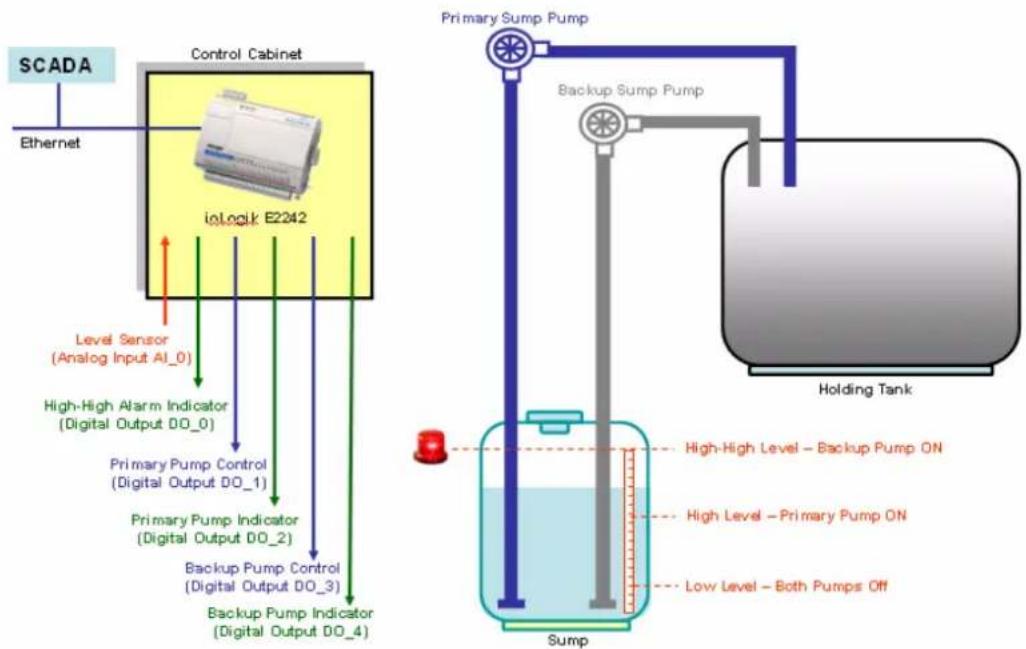
flowchart
graph TD
    A["SCADA"] --> B["Control Cabinet"]
    B --> C["ioLock E2242"]
    C --> D["Level Sensor (Analog Input AI_0)"]
    C --> E["High-High Alarm Indicator (Digital Output DO_0)"]
    C --> F["Primary Pump Control (Digital Output DO_1)"]
    C --> G["Primary Pump Indicator (Digital Output DO_2)"]
    C --> H["Backup Pump Control (Digital Output DO_3)"]
    C --> I["Backup Pump Indicator (Digital Output DO_4)"]
    J["Primary Sump Pump"] --> K["Holding Tank"]
    L["Backup Sump Pump"] --> K
    M["Sump"] --> N["High-High Level - Backup Pump ON"]
    M --> O["High Level - Primary Pump ON"]
    M --> P["Low Level - Both Pumps Off"]
Click&Go Programming Example I/O Alias Configuration
- Analog Input AI_0: Level Sensors.
- Digital Output DO_0: High-high Alarm.
- Digital Output DO_1: Primary Pump Control.
- Digital Output DO_2: Primary Pump Indicator.
- Digital Output DO_3: Backup Pump Control.
- Digital Output DO_4: Backup Pump Indicator.
- Internal Register_0: Remote Primary Pump Control.
- Internal Register_1: Remote Backup Pump Control.
I/O Mode Configuration
- Configure the DIO channel to DO mode, set the alias name for each channel.
- Configure the AI channel to 4-20 mA mode, set the alias name for each channel.
| Channel# | Range | Value | Min. | Max. |
| [Level Sensor]:00 | 4-20mA | 4.000 mA | 4.000 mA | 4.000 mA |
| Channel | Mode | Status | ||
| [High-high]:00 | DO | OFF | ||
| [Primary Pump]:01 | DO | OFF | ||
| [Primary Ind.]:02 | DO | OFF | ||
| [Backup Pump]:03 | DO | OFF | ||
| [Backup Ind.]:04 | DO | OFF | ||
Programming Manners
- Primary Pump and its indicator is activated when liquid level reaches High (15 mA input)
- Backup Pump and its indicator is activated when the liquid level reaches High-high (18 mA input), incase the primary pump is fail. High-high Alarm is triggered as well.
- High-high Alarm is OFF when the liquid level goes back to High Level, both pumps keep working
- Primary Pump and its indicator is deactivated when the liquid level reaches Low (7 mA input)
- Backup Pump and its indicator is deactivated when the liquid level reaches Low (7 mA input)
- E-mail warning when reaching the High-high level
- Remote control the primary/backup pump manually (Internal Register 0/1)
Click&Go Rule-set
| #0 | Enabled | : (Primary Pump-1 = ON) AND (Primary Ind. -2 = ON) | |
| #1 | Enabled | : (Backup Pump-3 = ON) AND (Backup Ind. -4 = ON) AND (High-high-0 = ON) | |
| #2 | Enabled | : (High-high-0 = OFF) | |
| #3 | Enabled | : (Primary Pump-1 = OFF) AND (Primary Ind. -2 = OFF) AND (Internal Register-0 = 0) | |
| #4 | Enabled | : (Backup Pump-3 = OFF) AND (Backup Ind. -4 = OFF) AND (Internal Register-1 = 0) | |
| #5 | Enabled | : (Send E-Mail) |
Applications\_5
The ioLogik E2214 reduces downtime in a runway perimeter security system.
Project Background
Relay control for lighting and motion detection is at the heart of a runway perimeter intrusion detection and alarm system application. On a typical day, aircraft constantly come and go on both the runway and adjacent taxiways, creating a dangerous environment for anyone or anything entering the runway. For this reason, installing a stand-alone, remote control system for intrusion detection and issuing alarms is an absolute necessity for avoiding accidents.

natural_image
Front view of a large aircraft on the tarmac at sunset with illuminated landing lights (no visible text or symbols)Application Requirements
Besides motion sensors, alarm lights, and a second-tier (external) relay board, a remote controller is the most important component inside the device cabinet. Programming power on the controller should be available to perform the local control. At the same time, the relay components on a second-tier relay board should be replaced in advance to avoid failures when they wear out. On average, the relays can be used 25,000 times, but should be replaced after being used 10,000 times to avoid unexpected failures. The local controller not only controls the on/off functions of the alarm lights when the sensors are activated, but is also required to send a warning when the usage of a specific channel of the second-tier relay board reaches 10,000 times.
Moxa Solution
The ioLogik E2214 is designed with 6 DI and 6 relay channels. With the user-friendly Click&Go local control logic, users can easily program the ioLogik E2214 as the front-end relay controller to detect intrusions. Click&Go also supports a special function called "relay counter storage" to provide readings of the current relay usage. This allows the ioLogik E2214 to send out TCP packets to the central SCADA system and a warning e-mail at the same time so that site maintainers can replace the relay components of the second-tier relay board. After the replacement, site maintainers simply press the RESET button attached to the ioLogik E2214 to clear the counts. In other words, there is no need to use laptop computers or remote commands.
Solution Benefits
The Moxa ioLogik E2214 provided the runway security system with the following benefits:
Click&Go's easy IF-THEN-ELSE style control logic, which eliminates the need for a PLC or RTU
√ Active reports via TCP/UDP/SNMP trap and e-mail
√ Relay count reports
√ Compact size and cost-effectiveness
Additional Features
The ioLogik E2214 is also equipped with the following features:
√ Local alarm output using digital channels
√ Alarm notifications via e-mail
√ Periodic status updates with SNMP trap
√ Moxa's Active OPC Server to connect ioLogik devices to the most popular SCADA systems
System Diagram
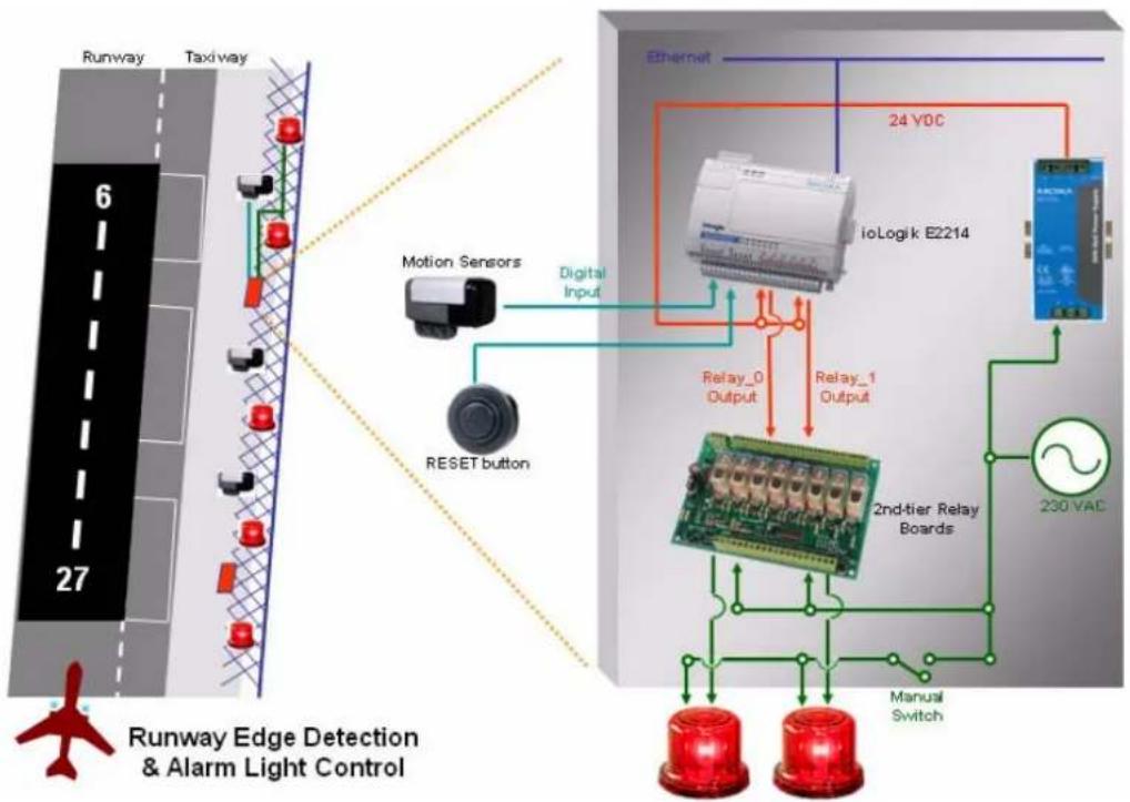
flowchart
graph TD
    A["Runway Edge Detection & Alarm Light Control"] --> B["Runway"]
    B --> C["Taxway"]
    C --> D["Digital Input"]
    D --> E["Motion Sensors"]
    E --> F["RESET button"]
    F --> G["Relay_0 Output"]
    G --> H["ioLogik E2214"]
    H --> I["230 VAC"]
    I --> J["Manual Switch"]
    J --> K["2nd-tier Relay Boards"]
    K --> L["Relay_1 Output"]
    L --> M["24 VDC"]
    M --> N["Ethernet"]
    N --> O["27"]
    style A fill:#f9f,stroke:#333
    style B fill:#ccf,stroke:#333
    style C fill:#cfc,stroke:#333
    style D fill:#fcc,stroke:#333
    style E fill:#cff,stroke:#333
    style F fill:#ffc,stroke:#333
    style G fill:#fcf,stroke:#333
    style H fill:#cff,stroke:#333
    style I fill:#ffc,stroke:#333
    style J fill:#cfc,stroke:#333
    style K fill:#fcc,stroke:#333
    style L fill:#ffc,stroke:#333
    style M fill:#cfc,stroke:#333
    style N fill:#fcc,stroke:#333
Click&Go Programming Example
I/O Alias Configuration
- Configure the alias name of DI_0 channel to MotionSensor#0.
- Configure the alias name of DI_1 channel to RESET#0.
- Configure the alias name of DO_0 channel to Light#0.
| Channel | Mode | Status | Filter | Trigger |
| [MotionSensor#1 | DI | OFF | 50.0 ms | -- |
| [RESET]:01* | DI | OFF | 50.0 ms | -- |
| Channel | Mode | Status | Low | High |
| [Light#1]:00 | DO | OFF | -- | -- |
Programming Manners
- Lights should be turned ON locally (for the motion sensor) and remotely
- Report the current relay counts via e-mail upon reaching 1,000 uses
- After a relay is replaced, site maintainers can manually reset the counts by pressing the RESET button
Click&Go Rule-set
| #0 | Enabled | : (Light#1-0 = ON) : (Light#1-0 = OFF) | |
| #1 | Enabled | : (Send E-Mail) | |
| #2 | Enabled | : (Reset RelayCnt-0) |
NOTE
Internal Register-0 in this case is used to control the relay output to a light. The control is done outside the ioLogik or locally depending on the DI status when running Click&Go logic. Refer to the appendix for the Modbus/TCP Address table of the internal registers.
Applications\_6
The ioLogik E2212 collects meter readings for a yacht wharf billing system.
Project Background
Patrons generally require refueling and battery charging as basic services after docking their yachts at a hotel's wharf. Upon disembarking, customers simply connect their yachts to the charge station and check in at the front desk. The hotel wanted a system to remotely start the charge station after customers check in and stop the charge station after they check out. More importantly, the hotel wanted to integrate the charge station meter readings with an electronic billing system.

natural_image
Harbor scene with numerous sailboats docked under a clear blue sky (no visible text or signage)Application Requirements
The original system in place required patrons to manually check the electricity readings at the charge station and return to the hotel for check out. This system worked fine when the weather was good and patrons did not have to travel a far distance between their yacht and the hotel. However, when the conditions were bad, there were complaints. In addition, protecting against electricity thieves was also quite difficult. Therefore, the hotel wanted to integrate remote control and data acquisition into the billing system to address these issues.
Moxa Solution
The ioLogik E2212 Active Ethernet I/O server is designed for mixed I/O applications. The 8 digital inputs and 4 configurable DIOs offer great connectivity to the power switches and electricity meters. With the world's easiest to program local control logic, Click&Go, users can easily program the ioLogik E2212 as a front-end controller in a short time, control and record the electricity supply, and send readings as ASCII text messages that can be easily integrated into the billing system.
Solution Benefits
The ioLogik E2212 provided the yacht wharf billing system with the following benefits:
√ A controller equipped with both digital inputs and digital output channels
√ Easy IF-THEN-ELSE style Click&Go control logic, which eliminates programming and debugging effort, and replaces the PLC or RTU
√ Backup storage for meter readings when the ioLogik's power does down
√ Alarm messaging via TCP/UDP/SNMP trap or e-mail
√ Compact size and cost-effectiveness
Additional Features
The ioLogik E2212 is also equipped with the following features:
√ Battery status detection to prevent over-charging the battery
√ Moxa's Active OPC Server to connect ioLogik devices to the most popular SCADA systems
System Diagram
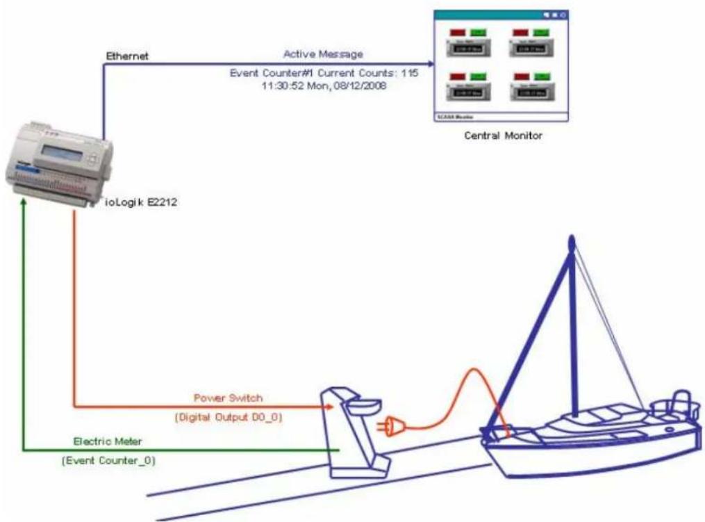
flowchart
graph TD
    A["ioLogik E2212"] -->|Ethernet| B["Central Monitor"]
    B -->|Active Message Event Counter#1 Current Counts: 115 11:30:52 Mon, 08/12/2008| C["SCAB Monitor"]
    C --> D["Power Switch (Digital Output D0_0)"]
    D --> E["Electric Meter (Event Counter_0)"]
Click&Go Programming Example
I/O Alias and Mode Configuration
- Configure the 1^st input channel to Event Counter mode, and Power On Settings to "START". Configure the alias to Meter#1.

- Configure the 1^st digital output's alias to PWR_Switch#1
| Channel | Mode | Status | Filter | Trigger |
| [Meter#1]:00* | Counter | 0 | 50.0 ms | L2H |
| Channel | Mode | Status | Low | High |
| [PWR_Switch#1]:00* | DO | OFF | -- | -- |
Programming Manners
- Turn on the power switch remotely and start recording the counts.
- Turn off the power switch remotely and stop recording the counts. Report the readings and reset the counter.
Click&Go Rule-set
| #0 | Enabled | : (Internal Register-0 =1) | : (Power Swirch#1-0 = ON) : (Power Swirch#1-0 = OFF) AND (Send Active Message) AND (Reset Counter-0) |
NOTE
Internal Register-0 in this case is used to control the power switch attached to the digital output channel. The control is done outside the ioLogik when running Click&Go logic. Refer to the appendix for the Modbus/TCP Address table of the internal registers.
Applications\_7
The ioLogik E2210 handles the safety and alarm system of a public restroom.
Project Background
Security and safety systems in public facilities such as train stations, museums, and movie theaters, are increasingly incorporating medical assistance, police, and fire alarms for patrons to trigger in emergency situations. In particular, public restrooms are deploying emergency alarm systems to assist women, handicapped patrons, and parents with children.

natural_image
Interior view of a bathroom with toilet, sink, and shower (no visible text or symbols)Application Requirements
Several types of emergency push buttons are required for this application. In the women's restroom, there needs to be an individual emergency push button in each toilet stall and another one on the wall near the entrance. Handicap stalls include two types of buttons. One type of button calls for medical assistance and is located near the flush handle under a plastic covering. In case the patron falls down while moving between the toilet and his wheelchair, suffers a heart attack, or is unable to get back up for any other reason, there is another emergency button located near the floor to provide better assistance. In most cases, it is attached to the other call button by 2 meters of expansion cable. The emergency button located near the door is designed primarily for people walking by to report a fire alarm or accident.
After an emergency button is triggered, alarm lights will start flashing and the speaker will start broadcasting for 30 to 60 seconds. This event will be reported to the control center as well. After receiving the alarm, the control center can remotely turn off the alarm light outside the restroom. Finally, security personnel or paramedics will arrive.
Moxa Solution
The ioLogik E2210 Active Ethernet I/O server is designed for mixed I/O applications. The 12 digital inputs can connect to various kinds of sensors and switches and the 8 built-in digital outputs provide the best flexibility in connecting to multiple alarm devices. With the world's easiest local control logic, Click&Go, users can easily program the ioLogik E2210 as a front-end alarm controller to automatically generate the response actions, such as the alarm lights and speaker, when the emergency buttons are activated.
Solution Benefits
The ioLogik E2210 provides the restroom alarm system with the following benefits:
√ A controller equipped with both digital input and digital output channels
√ More local input functions such as local acknowledgement and open detection of the control box
Click&Go's easy IF-THEN-ELSE style control logic, which eliminates the need for a PLC or RTU
√ Simultaneous control for local and remote Ethernet
√ Alarm messaging can be generated via TCP, UDP, or SNMP trap, or e-mail
√ Compact size and cost-effectiveness
Additional Features
The ioLogik E2210 is also equipped with the following features:
√ CGI Command to integrate video surveillance to record or take snapshots during an emergency
√ Moxa's Active OPC server to connect Logik devices to the most popular SCADA systems.
System Diagram
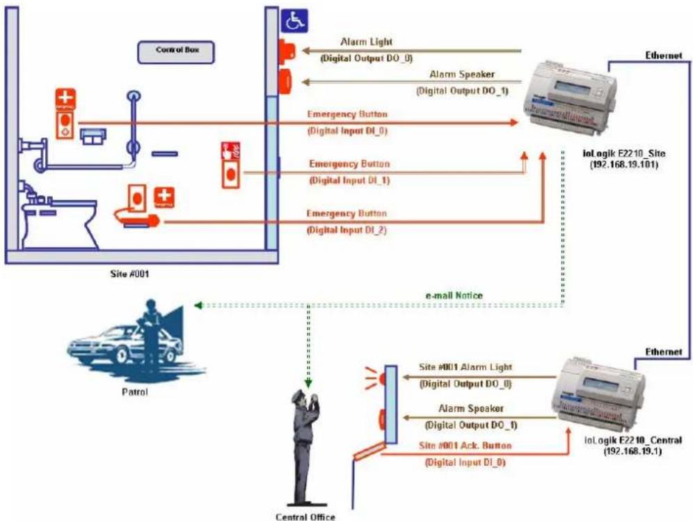
flowchart
graph TD
    A["Control Box"] --> B["Site #001"]
    B --> C["Patrol"]
    C --> D["Central Office"]
    D --> E["Alarm Light (Digital Output DO_0)"]
    D --> F["Alarm Speaker (Digital Output DO_1)"]
    D --> G["Emergency Button (Digital Input DI_0)"]
    D --> H["Emergency Button (Digital Input DI_1)"]
    D --> I["Emergency Button (Digital Input DI_2)"]
    E --> J["Ethernet"]
    F --> J
    G --> J
    H --> J
    I --> J
    J --> K["IoLogik E2210_Site (192.168.19.101)"]
    K --> L["Central Office"]
    L --> M["Alarm Light"]
    L --> N["Alarm Speaker"]
    L --> O["Emergency Button"]
    L --> P["Emergency Button"]
    M --> Q["IoLogik E2210_Central (192.168.19.1)"]
    N --> Q
    O --> Q
    P --> Q
    Q --> R["Ethernet"]
Click&Go Programming Example\_Site
I/O Alias and Timer Configuration of ioLogik\_Site
- Digital Input DI_0: Higher Emergency Button.
- Digital Input DI_1: Lower Emergency Button.
- Digital Input DI_2: Front-end Emergency Button.
- Digital Output DO_0: Alarm Light.
- Digital Output DO_1: Alarm Speaker.
| Channel | Mode | Status | Filter | Trigger |
| [EM_High]:00* | DI | OFF | 50.0 ms | -- |
| [EM_Low]:01* | DI | OFF | 50.0 ms | -- |
| [EM_Front]:02* | DI | OFF | 50.0 ms | -- |
| Channel | Mode | Status | Low | High |
| [Alarm Light]:00* | DO | OFF | -- | -- |
| [Alarm Speaker]:01* | DO | OFF | -- | -- |
- In the Click&Go Manual configure the Timer to 60 seconds.
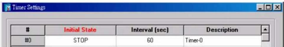
Programming Manners of ioLogik E2210\_Site
- No matter which emergency is triggered, switch on the local alarm light and speaker.
- No matter which emergency is triggered, send out e-mail notice to central administrator and the patrol.
- No matter which emergency is triggered, switch on the central Alarm Light for this specific site.
- No matter which emergency is triggered, switch on the central alarm Speaker (there is only on speaker at central).
- After 60 seconds, switch off the local Alarm Speaker.
- Receiving an acknowledgement from central, switch off the local Alarm Light
Click&Go Rule-set of ioLogik E2210_Site
| #0 | Enabled | ||
| #1 | Enabled | ||
| #2 | Enabled | ||
| #3 | Enabled |
Logic #1 - Sending Remote Action to ioLogik E2210_Central
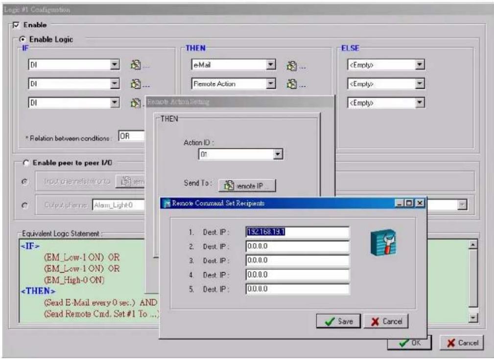
NOTE
This Remote Action ID is configured to trigger both the remote (central) Alarm Light and Speaker.
Remote Action IP and ID mapping is shown as below:
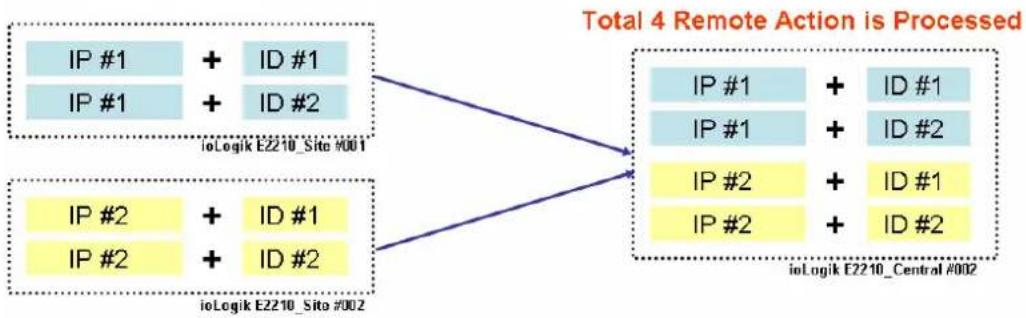
flowchart
graph TD
    A["IP #1 + ID #1"] --> D["Total 4 Remote Action is Processed"]
    B["IP #1 + ID #2"] --> D
    C["IP #2 + ID #1"] --> D
    E["IP #2 + ID #2"] --> D
    F["IP #1 + ID #1"] --> D
    G["IP #1 + ID #2"] --> D
    H["IP #2 + ID #1"] --> D
    I["IP #2 + ID #2"] --> D
    J["ioLogik E2210_Sito #001"] --> D
    K["ioLogik E2210_Sito #002"] --> D
Logic #3 - Receiving Remote Action from ioLogik E2210_Central
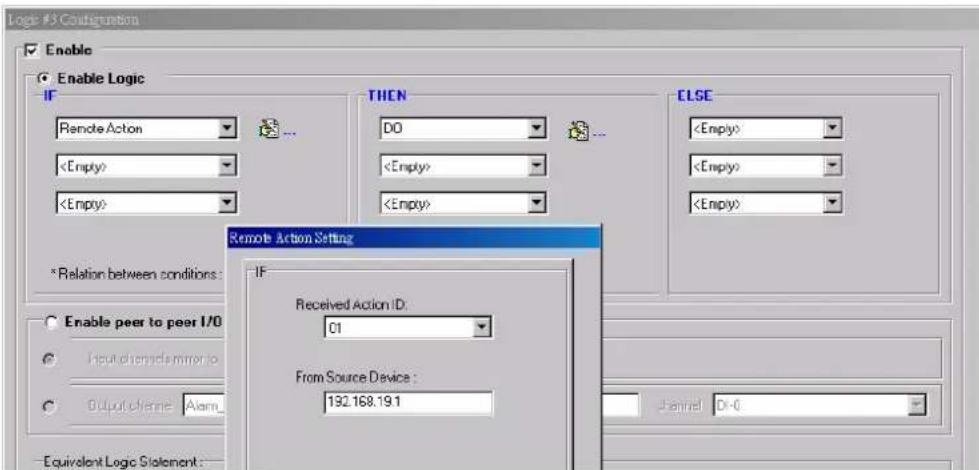
NOTE Receiving this Remote Action will disable the local (site) Alarm Light
Click&Go Programming Example\_Central
I/O Alias and Timer Configuration of ioLogik\_Central
- Digital Input DI_0: Site #001 Ack, Button.
- Digital Output DO_0: Site #001 Alarm Light.
| Channel | Mode | Status | Filter | Trigger |
| [Ack_001]:00 | DI | OFF | 50.0 ms | -- |
| Channel | Mode | Status | Low | High |
| [Alarm_001]:00 | DO | OFF | -- | -- |
| [Alarm Speaker]:01 | DO | OFF | -- | -- |
Programming Manners of ioLogik E2210\_Central
- Switch on the specific Alarm Light when an alarm from that site is activated.
- Switch on the Alarm Speaker when an alarm from any site is activated.
- An Acknowledge Button is used to disable the local (central) alarm light, local Alarm Speaker, and the remote (site) Alarm Light.
Click&Go Rule-set of ioLogik E2210\_Central
| #0 | Enabled | : (Receive Remote Cmd. Set #1 from IP=192.168.19.101) | : (Alarm_001-0 = ON) | |
| #1 | Enabled | : (Receive Remote Cmd. Set #2 from IP=192.168.19.101) | : (Alarm Speaker-1 = ON) | |
| #2 | Enabled | : (Ack_001-0 ON) | : (Alarm_001-0 = OFF) AND (Alarm Speaker-1 = OFF) AND (Send Remote Cmd. Set #1 To...) |
Logic #0 - Receiving Remote Action from ioLogik E2210_Site
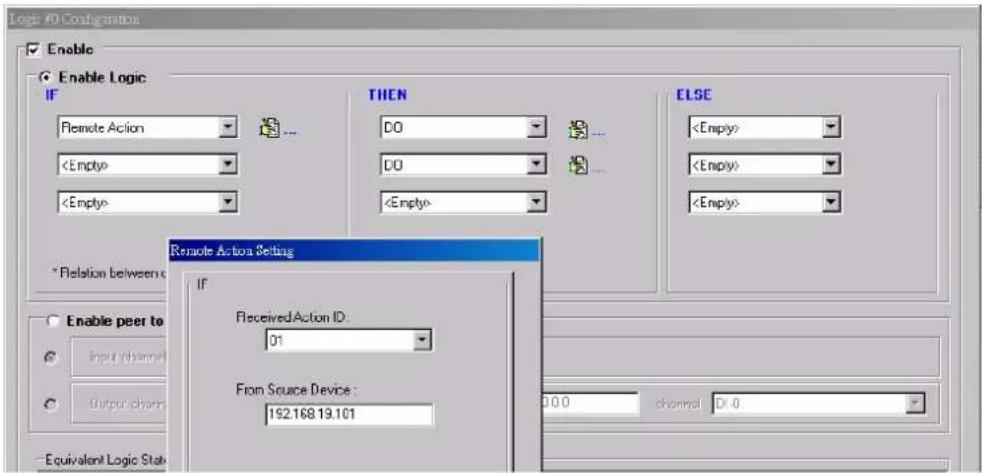
NOTE
This Remote Action disables the remote (site) Alarm Light.
Logic #2 - Sending Remote Action from ioLogik E2210_Site
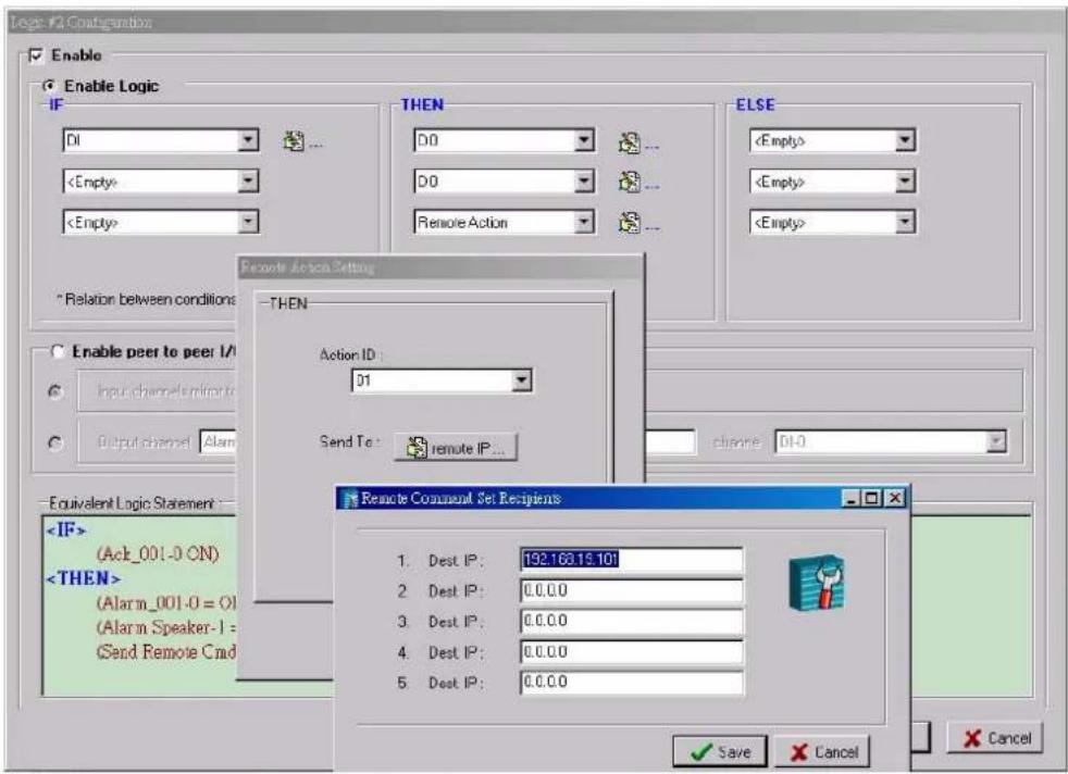
NOTE
This Remote Action disables the remote(site) Alarm Light
ioLogik E2210, E2212 and E2214
4xxxx Read/Write Registers (Functions 3, 6, 16)
| Reference | Address | Data Type | Description |
| 40377 0x0178 | word Internal | Register 00 | Value |
| 40378 0x0179 | word Internal | Register 01 | Value |
| 40379 0x017A | word Internal | Register 02 | Value |
| 40380 0x017B | word Internal | Register 03 | Value |
| 40381 0x017C | word Internal | Register 04 | Value |
| 40382 0x017D | word Internal | Register 05 | Value |
| 40383 0x017E | word Internal | Register 06 | Value |
| 40384 0x017F | word Internal | Register 07 | Value |
| 40385 0x0180 | word Internal | Register 08 | Value |
| 40386 0x0181 | word Internal | Register 09 | Value |
| 40387 0x0182 | word Internal | Register 10 | Value |
| 40388 0x0183 | word Internal | Register 11 | Value |
| 40389 0x0184 | word Internal | Register 12 | Value |
| 40390 0x0185 | word Internal | Register 13 | Value |
| 40391 0x0186 | word Internal | Register 14 | Value |
| 40392 0x0187 | word Internal | Register 15 | Value |
| 40393 0x0188 | word Internal | Register 16 | Value |
| 40394 0x0189 | word Internal | Register 17 | Value |
| 40395 0x018A | word Internal | Register 18 | Value |
| 40396 0x018B | word Internal | Register 19 | Value |
| 40397 0x018C | word Internal | Register 20 | Value |
| 40398 0x018D | word Internal | Register 21 | Value |
| 40399 0x018E | word Internal | Register 22 | Value |
| 40400 0x018F | word Internal | Register 23 | Value |
ioLogik E2240, E2242, E2260 and E22262
4xxxx Read/Write Registers (Functions 3, 6, 16)
| Reference | Address | Data Type | Description |
| 40337 0x0150 | word Internal | Register 00 | Value |
| 40338 0x0151 | word Internal | Register 01 | Value |
| 40339 0x0152 | word Internal | Register 02 | Value |
| 40340 0x0153 | word Internal | Register 03 | Value |
| 40341 0x0154 | word Internal | Register 04 | Value |
| 40342 0x0155 | word Internal | Register 05 | Value |
| 40343 0x0156 | word Internal | Register 06 | Value |
| 40344 0x0157 | word Internal | Register 07 | Value |
| 40345 0x0158 | word Internal | Register 08 | Value |
| 40346 0x0159 | word Internal | Register 09 | Value |
| 40347 0x015A | word Internal | Register 10 | Value |
| 40348 0x015B | word Internal | Register 11 | Value |
| 40349 0x015C | word Internal | Register 12 | Value |
| 40350 0x015D | word Internal | Register 13 | Value |
| 40351 0x015E | word Internal | Register 14 | Value |
| 40352 0x015F | word Internal | Register 15 | Value |
| 40353 0x0160 | word Internal | Register 16 | Value |
| 40354 0x0161 | word Internal | Register 17 | Value |
| 40355 0x0162 | word Internal | Register 18 | Value |
| 40356 0x0163 | word Internal | Register 19 | Value |
| 40357 0x0164 | word Internal | Register 20 | Value |
| 40358 0x0165 | word Internal | Register 21 | Value |
| 40359 0x0166 | word Internal | Register 22 | Value |
| 40360 0x0167 | word Internal | Register 23 | Value |