RE2PRMK45U280B - Unspecified EATON - Free user manual and instructions
Find the device manual for free RE2PRMK45U280B EATON in PDF.

User questions about RE2PRMK45U280B EATON
0 question about this device. Answer the ones you know or ask your own.
Ask a new question about this device
Download the instructions for your Unspecified in PDF format for free! Find your manual RE2PRMK45U280B - EATON and take your electronic device back in hand. On this page are published all the documents necessary for the use of your device. RE2PRMK45U280B by EATON.
USER MANUAL RE2PRMK45U280B EATON
RE 2 Post Rack System
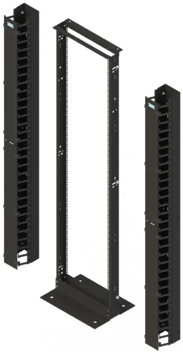
natural_image
Three black server rack units with vertical connectors, shown from different angles (no text or symbols visible)TABLE OF CONTENTS
SAFETY WARNINGS 3
Frame Assembly Guide 4 - 6
Vertical Cable Manager Assembly Guide 7 + 8
Adjustable Cable Spools 9 + 10
Vertical Cable Basket 11
Earth Bonding 12
1. SAFETY WARNINGS

This manual contains important instructions that you should follow during installation and maintenance of the RE 2 Post Rack system. Please read all instructions before operating the equipment and save this manual for future reference.
- WARNING! RE 2 Post Rack components can be very heavy. When lifting heavy components or electronic equipment, ensure that all safety regulations are observed.
- WARNING! The enclosure must be stabilized (bolted to floor) before installing any accessory, component or electronic device. Failure to stabilize prior to installing equipment may cause the enclosure to tip over.
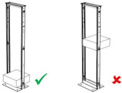
- WARNING! First, load the heaviest electronic devices and accessories into the bottom of the rack to prevent the rack from becoming top-heavy and ensure the 19" equipment is evenly loaded front to back in the RE 2 Post Rack (see diagram below);
natural_image
Two identical vertical metal frame structures with a green checkmark and red X mark, no text or symbols present.- WARNING! It is the customer's responsibility to ensure that the floor has a structural load capacity that will safety bear the weight of the RE 2 Post Rack and installed components.
- WARNING! There must be an uninterruptable safety earth ground from the main power source to the Power Distribution Unit's PDU (if fitted) power cord set. Whenever it is likely that ground has been impaired, disconnect the PDU's power cord until the ground has been restored.
- WARNING! High leakage current may be present. Grounding connection essential before connecting supply.
- WARNING! Rack is intended to be used with equipment complying with IEC 60950. Use with non-compliant equipment may result in electrical hazard.
- WARNING! The installer is responsible for grounding the RE 2 Post Rack to the building electrical system. Additional equipment can be electronically bonded to the rack's frame using additional grounding points and appropriate fixings.
2. RE 2 Post Rack Frame Assembly Guide
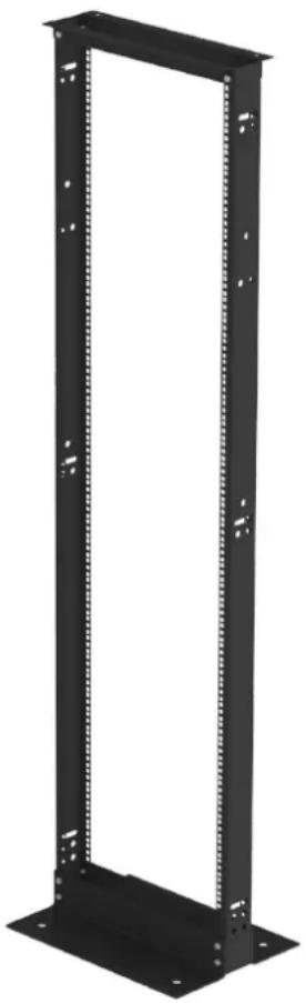
natural_image
Black vertical metal rack frame with mounting holes and mounting holes (no text or symbols)
text_image
1 2 3 4 5 6 7 8 9 10 11 12 13 14 15ITEM
DESCRIPTION
QTY
1 RE 2 POST VERTICAL MOUNTING RAIL 2
2 RE 2 POST BOTTOM ANGLE 2
3 RE 2 POST TOP ANGLE 2
4 M8 SHAKEPROOF WASHER 8
5 M8 x 20mm HEX HEAD BOLTS 8
6 BRACKET ASSEMBLY FOR PDU & CABLE BASKET 2
Installation Guide
. Step -1
Lay vertical mounting rails on a flat surface with the open sides of the channel facing each other. The rails should be approximately 450mm apart.

text_image
Item 5 Item 4 Item 2 Item 1Figure -1
. Step - 2
Place the bottom angle on the vertical mounting rails as shown in Figure 1.
Align the bottom angle holes with the holes in the vertical mounting rails. Fasten using 4 x M8 washers and 4 x M8 x 20 Hex Head bolts, then FINGER TIGHTEN.
. Step - 3
Place the top angle on the vertical mounting rails as shown in Figure 2.
Align the top angle holes with the holes in the vertical mounting rails. Fasten using 2 x M8 washers and 2 x M8 x 20 Hex Head bolts, then FINGER TIGHTEN.
. Step - 4
Turn the rack over and repeat Steps 2 and 3.

text_image
Item 5 Item 4 Item 3 Item 1Figure - 2
Installation Guide
. Step - 5
Stand the rack up and square as shown in Figure 3.
Tighten all fixings to 12 Nm (tolerance +/- 2 Nm)
. Step - 6
The bottom angles need to be secured to the floor (floor fixings not included)
. Step - 7
If required, install the 2 Cable Basket / PDU brackets to the RE 2 Post Rack vertical mounting rail side or, using cage nuts, to the 19" rail.
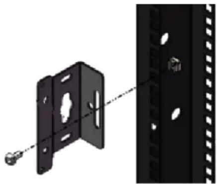
natural_image
Technical illustration of a metal bracket with mounting holes and a close-up view of its side panel (no text or symbols)Once secured to the floor the rack is now ready for equipment installation.

text_image
SQUAREFigure - 3
3. RE 2 Post Rack Vertical Cable Manager Assembly Guide

natural_image
Black vertical rack-mounted server unit with multiple slots and mounting holes (no text or symbols visible)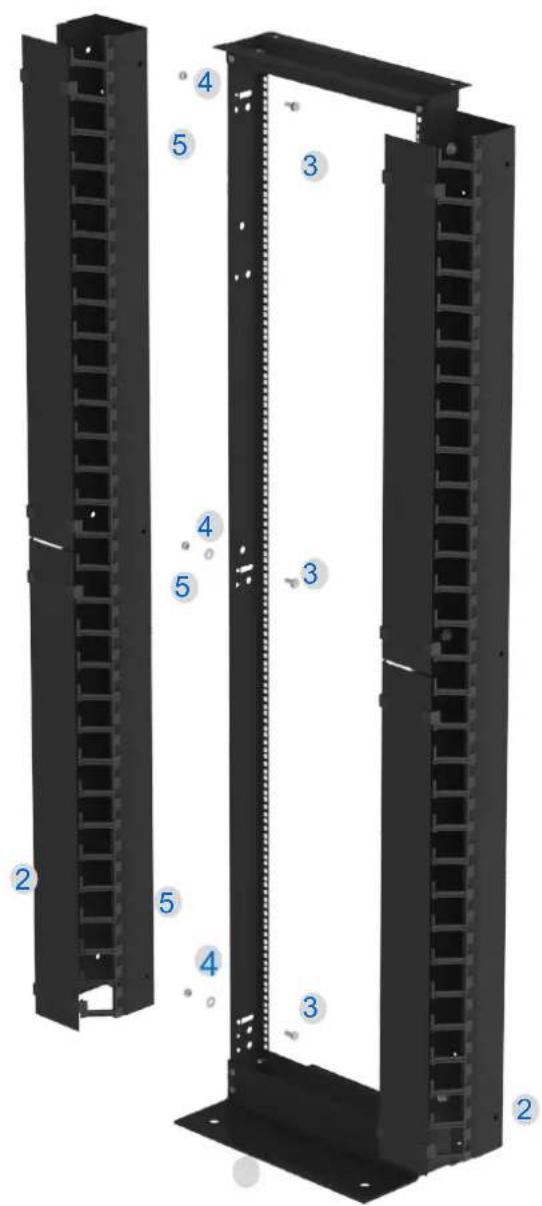
text_image
Technical diagram of a server rack with numbered components for identificationITEM DESCRIPTION QTY
1 RE 2 POST FRAME 1
2 RE CABLE MANAGER 2
3 M10 x 20 HEX HEAD BOLTS 6
4 M10 WASHER 6
5 M10 HEX FULLNUTS
8
Installation Guide
. Step -1
Ensure the RE 2 post frame is securely fastened to the floor.
2 person assembly - Person one offers the cable manager to the RE 2 Post frame whilst Person two passes the Item -3 through the frame (The fixing must pass through the obround slot in the 2 Post frame) into the Cable manager securing on the inside of the manager with a Item-4+5 then FINGER TIGHTEN. See figure-1
. Step - 2
Item 2
Fix the Cable manager in 3 places - Top, Middle & Bottom.

text_image
Item 5 Item 4 Item 3Figure -1
. Step - 3
Position the Cable Manager and Tighten all fixings to 12 Nm (tolerance +/- 2 Nm)
. Step - 4
Repeat step 1-2 on the opposite side of the RE 2 Post rack
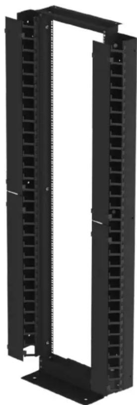
natural_image
Black vertical rack-mounted server unit with multiple slots and mounting feet (no text or symbols visible)RE 2 Post Rack Assembly and Installation Guide Issue 1
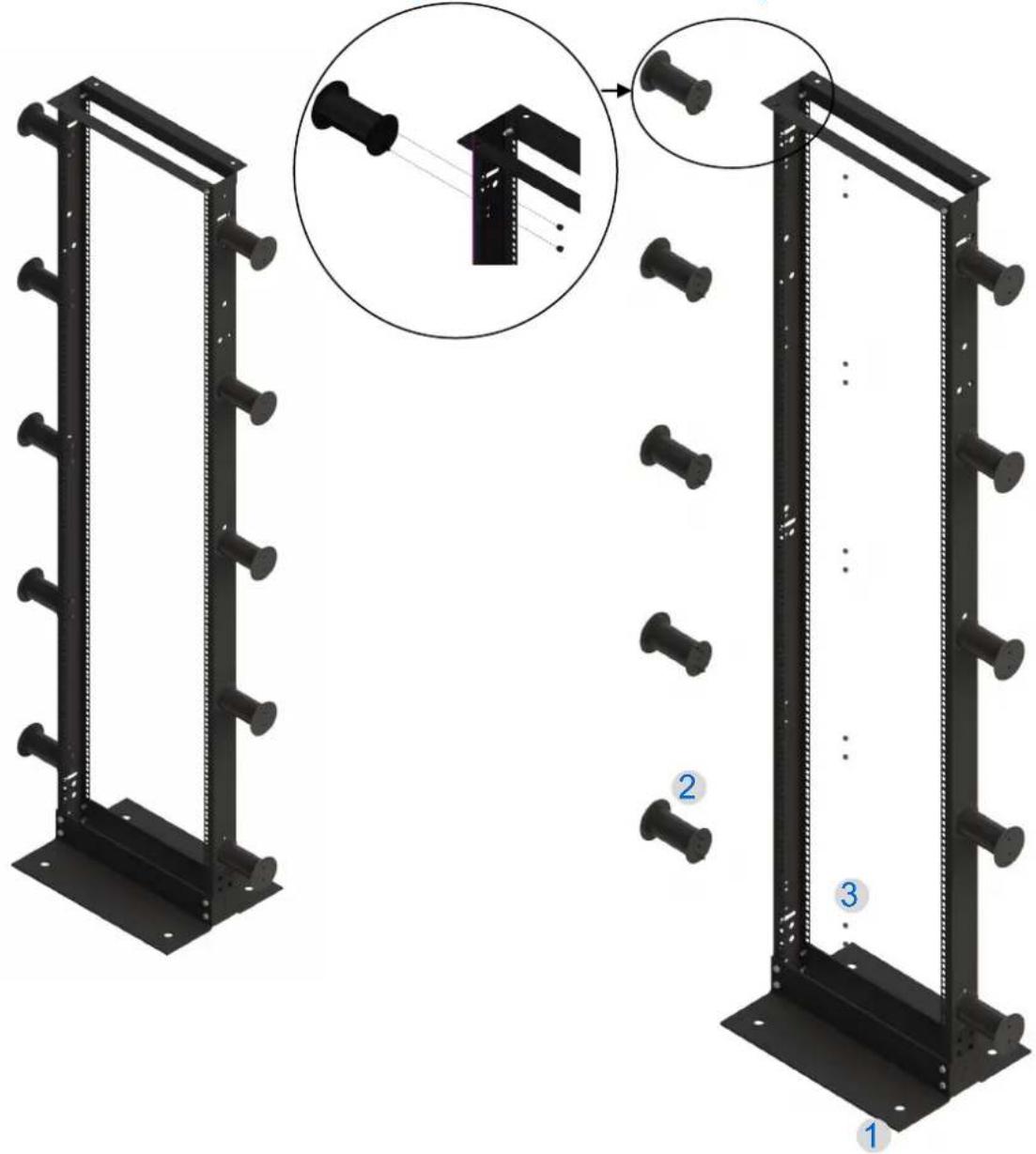
- RE 2 Post Rack Adjustable Cable Spools
text_image
Technical diagram showing assembly of server racks with numbered components and a magnified detail view highlighting structural details.ITEM DESCRIPTION QTY
1 RE 2 POST RACK 1
2 ADJUSTABLE CABLE SPOOL
5 PER KIT
3 M5 THUMB NUTS 2 PER SPOOL
Installation Guide
. Step -1
Ensure the RE 2 Post Rack frame is securely fastened to the floor.
Remove the thumb screws from spools where fitted See figure-1

natural_image
3D rendering of a black cylindrical object emitting laser beams into a server rack (no text or symbols visible)Figure -1
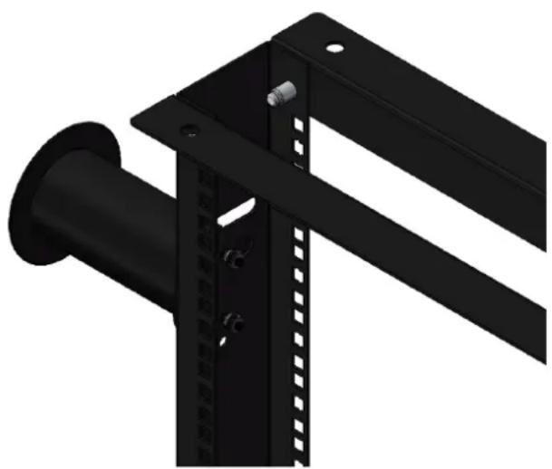
- Step - 2
Offer up a cable spool to the 2 holes in the vertical rail (Note there are 5 positions available on the rail). Thread on and tighten the thumb nuts.
. Step - 3
Repeat step 1-2 where required.
natural_image
3D rendering of a black mechanical bracket with mounting holes and a cylindrical component (no text or symbols visible)5. RE 2 Post Rack Vertical 300mm Cable Basket Assembly Guide.
. Step -1
Ensure the RE 2 Post Rack frame is securely fastened to the floor.
. Step -2
Secure the bracket to the RE 2 Post Rack vertical mounting rail.

natural_image
Technical diagram showing a metal bracket assembly with mounting holes and structural steel framework (no text or symbols). Step -3
Secure the cable basket to the bracket with the fixings and clamp plate supplied and tighten all fixings to 12Nm.
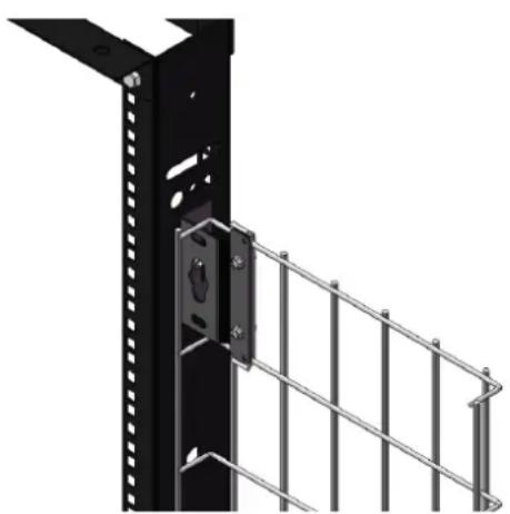
natural_image
Exterior view of a black metal-framed wall panel with a metal railing and mounting bracket (no text or symbols)Please note; 300mm Cable Basket is supplied with bracket assembly RE2PRCBPDUBA as detailed above. To mount 100mm or 200mm Cable Baskets in this way additional brackets RE2PRCBPDUBA will need to be ordered separately.
6. RE 2 Post Rack Earth Bonding.
The RE 2 Post Rack vertical mounting rails have earth bonding holes at both top and bottom. This enables easy earth bonding from above or below.
- Step - 1 1 serrated nut and bolt kit is supplied as standard for the purpose of earth bonding (see Fig 1). Locate this nut and bolt kit in the desired earth hole position and tighten to12Nm.
- Step - 2 Attach a pre-terminated earth wire to the bolt, then the washer and nut and tighten to12Nm.
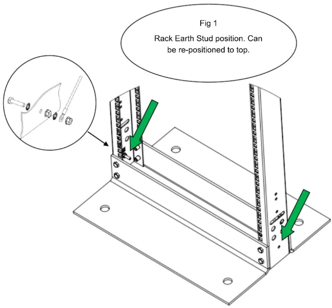
text_image
Fig 1 Rack Earth Stud position. Can be re-positioned to top.RE 2 Post Rack Assembly and Installation Guide Issue 1
Installation Guide
Eaton is dedicated to ensuring that reliable, efficient and safe power is available when it's needed most. With unparalleled knowledge of electrical power management across industries, experts at Eaton deliver customised, integrated solutions to solve our customers' most critical challenges.
Our focus is on delivering the right solution for the application. But, decision makers demand more than just innovative products. They turn to Eaton for an unwavering commitment to personal support that makes customer success a top priority.
For more information, visit www.eaton.eu/electrical
Eaton Industries Manufacturing GmbH
Electrical Sector EMEA
1110 Morges, Switzerland
© Copyright 2012
All rights reserved.
Changes to the products, to the information contained in this document, and to prices are reserved; so are errors and omissions. Only order confirmations and technical documentation by Eaton is binding. Photos and pictures also do not warrant a specific layout or functionality. Their use in whatever form is subject to prior approval by Eaton. The same applies to Trademarks (especially Eaton, Moeller, and Cutler-Hammer). The Terms and Conditions of Eaton apply, as referenced on Eaton internet pages and Eaton order confirmations.
Eaton is a registered trademark of Eaton Corporation.
All other trademarks are the property of their respective owners.