97-866 - Drawer Ergotron - Free user manual and instructions
Find the device manual for free 97-866 Ergotron in PDF.

User questions about 97-866 Ergotron
0 question about this device. Answer the ones you know or ask your own.
Ask a new question about this device
Download the instructions for your Drawer in PDF format for free! Find your manual 97-866 - Ergotron and take your electronic device back in hand. On this page are published all the documents necessary for the use of your device. 97-866 by Ergotron.
USER MANUAL 97-866 Ergotron
natural_image
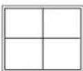
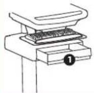
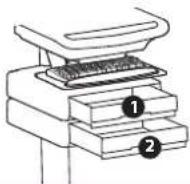
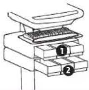
Diagram of a printer stacker with a load labeled 'LB kg' (no text or symbols on the diagram itself)Total weight capacity per drawer. Total weight capacity per drawer.

text_image
2.5" (64 mm)
text_image
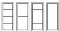
10.5" (267 mm) 12.5"(315 mm)


or

natural_image
Line drawing of a computer keyboard with three base stations and a weight tag (LB kg) at the bottom (no text or symbols on the diagram itself)≤0.25 lbs (0.1 kg) < 2 lbs (1 kg)
text_image
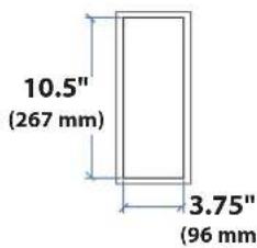
10.5" (267 mm) 3.75" (96 mm)
For the latest User Installation Guide please visit: www.ergotron.com

User's Guide - English Guía del usuario - Español Manuel de l'utilisateur - Français Gebruikersgids - Deutsch Benutzerhandbuch - Nederlands Guida per l'utente - Italiano Användarhandbok - svenska ユーザーガイド:日本語 用户指南:汉语

While Ergotron, Inc. makes every effort to provide accurate and complete information on the installation and use of its products, it will not be held liable for any editorial errors or omissions (including those made in the process of translation from English to another language), or for incidental, special or consequential damages of any nature resulting from furnishing this instruction and performance of equipment in connection with this instruction. Ergotron, Inc. reserves the right to make changes in the product design and/or product documentation without notification to its users. For the most current product information, or to know if this document is available in languages other than those herein, please contact Ergotron. No part of this publication may be reproduced, stored in a retrieval system, or transmitted in any form or by any means, electronic, mechanical, photocopying, recording or otherwise without the prior written consent of Ergotron, Inc., 1181 Trapp Road, Eagan, Minnesota, 55121, USA Patents Pending and Patented U.S. & Foreign. Ergotron is a registered trademark of Ergotron, Inc.

www.ergotron.com
USA 1-800-888-8458
Europe +31 (0)33-45 45 600
China 86-769-86018920
Americas Sales and
Corporate Headquarters
EMEA Sales
St. Paul, MN USA
(800) 888-8458
+1-651-681-7600
www.ergotron.com
sales@ergotron.com
Amersfoort, The Netherlands
+31 33 45 45 600
www.ergotron.com
info.eu@ergotron.com
APAC Sales
Worldwide OEM Sales
Tokyo, Japan
www.ergotron.com
www.ergotron.com
info.oem@ergotron.com
apaccustomerservice@ergotron.com

text_image
Two circular signs with pictograms: one for a mobile robot, the other for a wheeled cart with no prohibition.
CAUTION: Close worksurface before opening drawers. Open only one drawer at a time. Do Not push cart when drawers or worksurface are open. Failure to follow these instructions may cause the cart to be unstable.

text_image
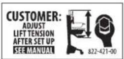
WARNING Ø 14nm (8/16°) IMPACT HAZARD! MOVING PARTS CAN CRUSH AND CUT. Minimize Lift Tension BEFORE: • Removing Mounted Equipment. • Shipping Cart • Storing Cart To Minimize Lift Tension 1. Lower worksurface to lowest position. 2. Turn adjustment nut at top of riser counterclockwise until it stops (Adjustment may require 40-60 revolutions). Failure to heed this warning may result in serious personal injury or property damage! For More information and instructions refer to product guide at http://support.ergotron.com or contact Ergotron Customer Care at 1-800-888-8458. 822-052
text_image
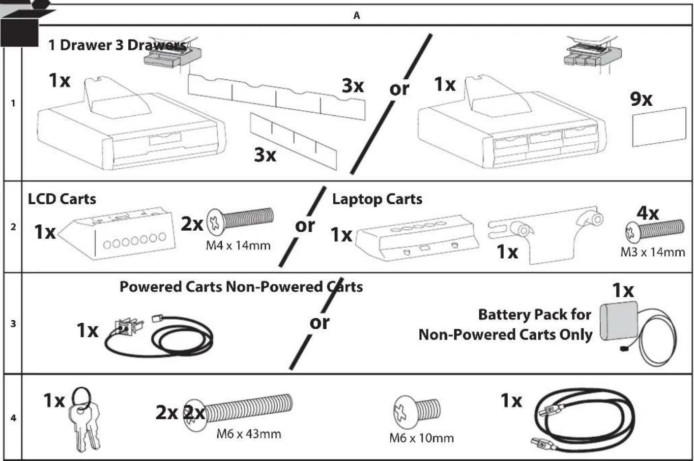
A 1 Drawer 3 Drawers 1x 3x or 1x 9x 3x 2 LCD Carts 1x 2x / Laptop Carts M4 x 14mm or 1x 1x 4x M3 x 14mm 3 Powered Carts Non-Powered Carts 1x or Battery Pack for Non-Powered Carts Only 4 1x 2x 2x M6 x 43mm M6 x 10mm 1x
natural_image
Illustration of three mechanical tools: a pencil holder, a screwdriver with a plus symbol, and a 14mm (9/16") tool (no text or symbols on the tools themselves)1 WARNING! Disconnect all power to the cart and turn off all mounted equipment before proceeding with this installation. Failure to follow this warning may result in serious injury and or equipment damage.
a Turn off all mounted equipment.
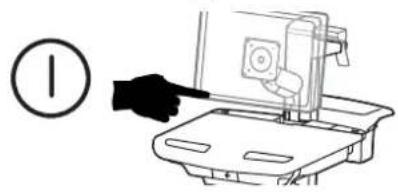
text_image
Diagram showing a hand pointing at a device with a numbered circle nearby, likely indicating a step or instruction.b Disconnect Power System from power source.
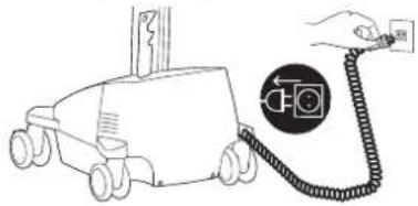
natural_image
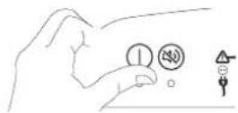
Line drawing of a toy car connected to a cable with a camera icon and a hand holding a power plug (no text or symbols)C Turn power system off by holding down the AC Outlet Power button for 1 - 3 seconds. Power light will shut off.
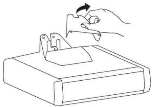
2 Remove the top cover.
natural_image
Line drawing of a hand turning a tool into a device component (no text or symbols)3 Hang the drawer tabs onto the brackets on the cart.
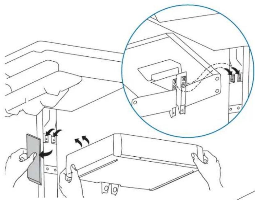
text_image
Technical diagram illustrating a mechanical assembly process with labeled components and directional arrows indicating motion or movement.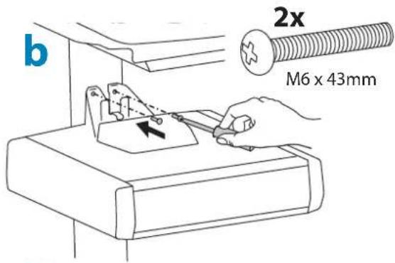
text_image
b 2x M6 x 43mm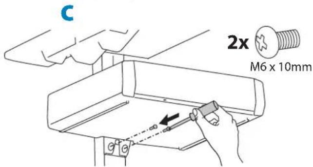
text_image
C 2x M6 x 10mm4
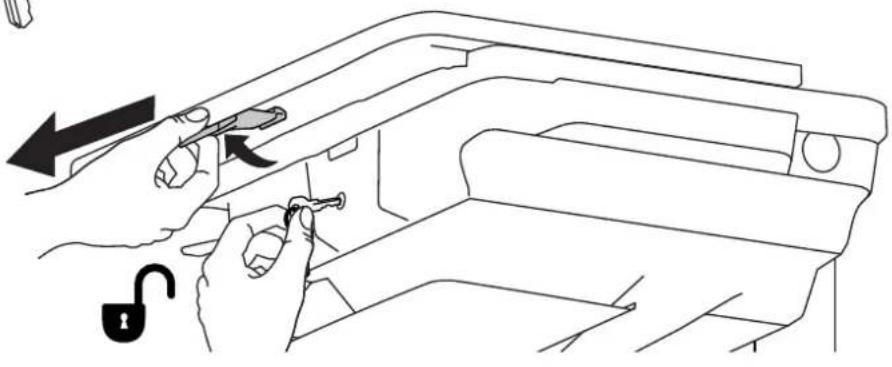
Open worksurface.
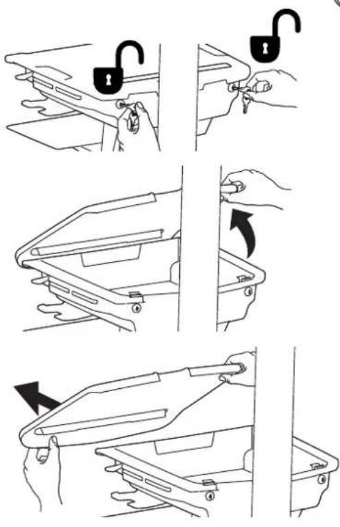
text_image
Diagram illustrating how to adjust a lock mechanism, showing step-by-step instructions for lifting or adjusting the lock.
LCD CartsLaptop Carts
natural_image
Line drawing of hands using a tool to adjust or install a mechanical component, with an open lock icon and directional arrow (no text or symbols)5
Route the USB cable from the drawer controller to the USB hub located inside the cart storage area.

text_image
Diagram illustrating network device connection with labeled ports and cable routing steps
Attach drawer keypad.
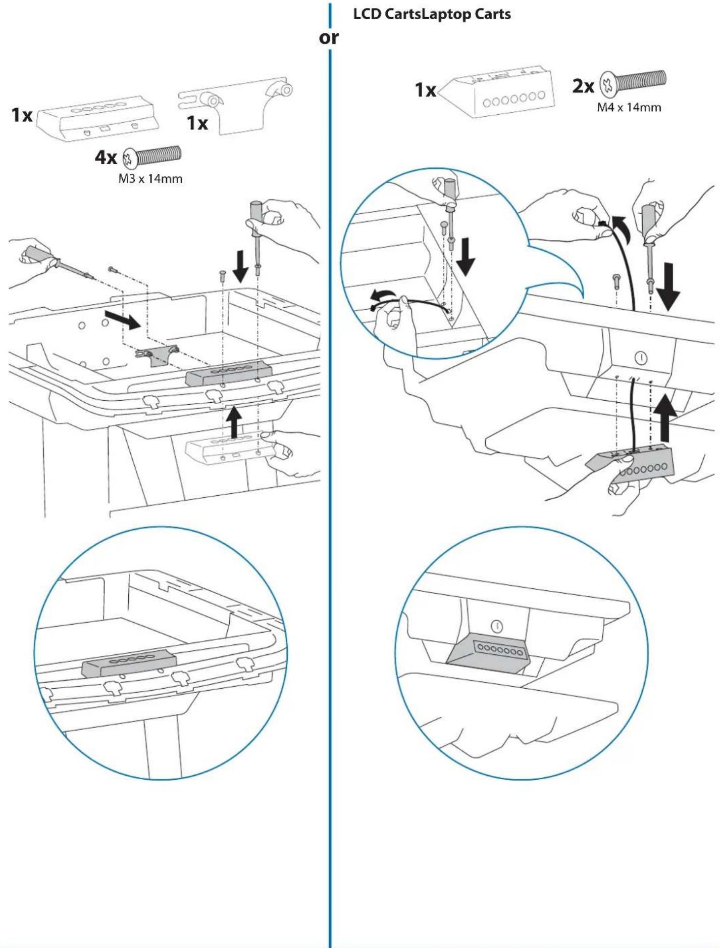
7 Route the keypad cable through the bottom of the storage area to the drawer controller.
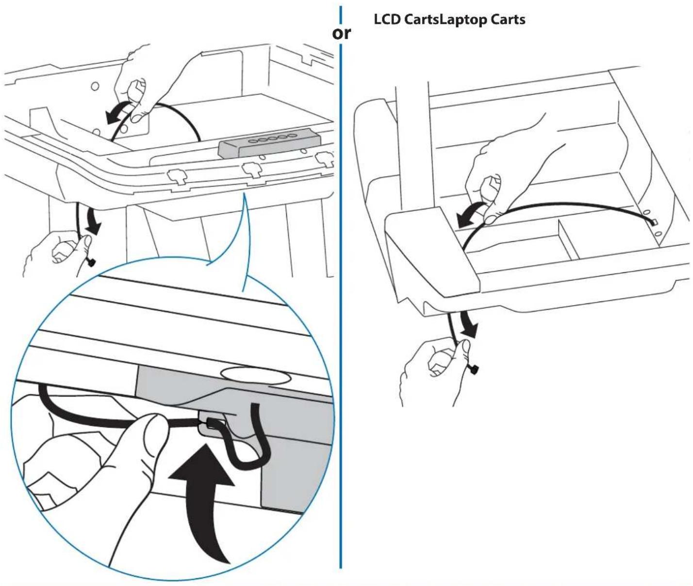
text_image
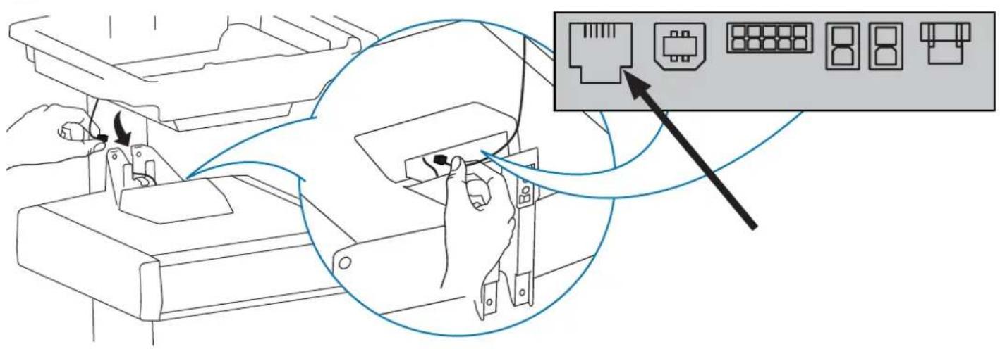
or LCD CartsLaptop Carts8 Plug the keypad's cable into the drawer controller.
text_image
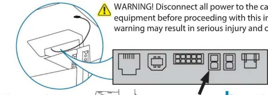
Diagram illustrating a device connection with labeled ports and a magnified view showing port layout.9
Route drawer power cable into base for Powered Carts Only
text_image
WARNING! Disconnect all power to the ca equipment before proceeding with this in warning may result in serious injury and oa
text_image
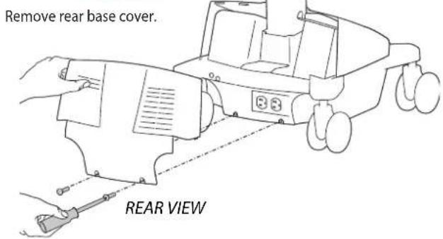
Remove rear base cover. REAR VIEWC
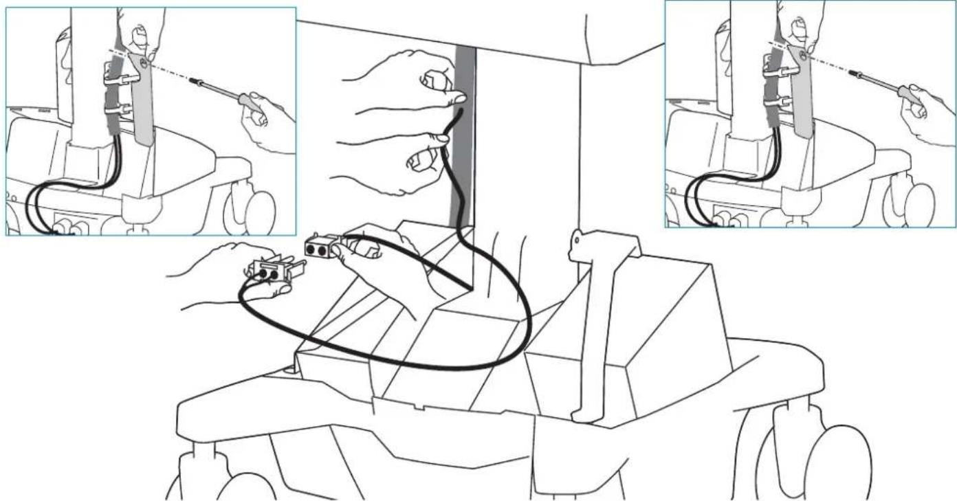
Remove cable management cover and route drawer power cable down into base and connect to power system.
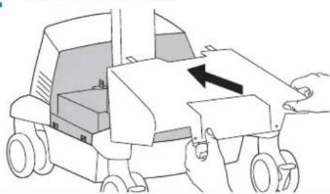
Remove front base cover.

text_image
b Remove front base cover. FRONT VIEW d Reattach cable management coverd
Reattach cable management cover.
natural_image
Line drawing of a robotic arm with cable and wires, showing three sequential steps (no text or symbols)e

text_image
Replace front base cover. FRONT VIEWf
Replace rear base cover.

text_image
place rear base cover. REAR VIEW9
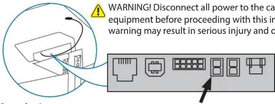
Route drawer power cable into base for Powered Carts Only
text_image
WARNING! Disconnect all power to the ca equipment before proceeding with this in warning may result in serious injury and oRemove front base cover.
a
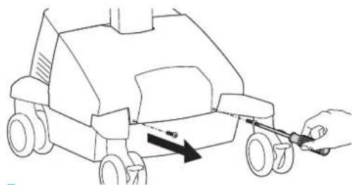
natural_image
Line drawing of a toy car with a hand holding a tool, showing motion direction (no text or symbols)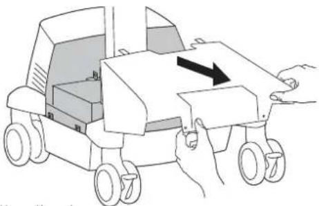
natural_image
Illustration of a toy car with wheels and a hand holding the side panel, showing no text or symbols.
natural_image
Line drawing of a robotic vehicle with hands operating it, showing wheel movement and motion arrows (no text or symbols)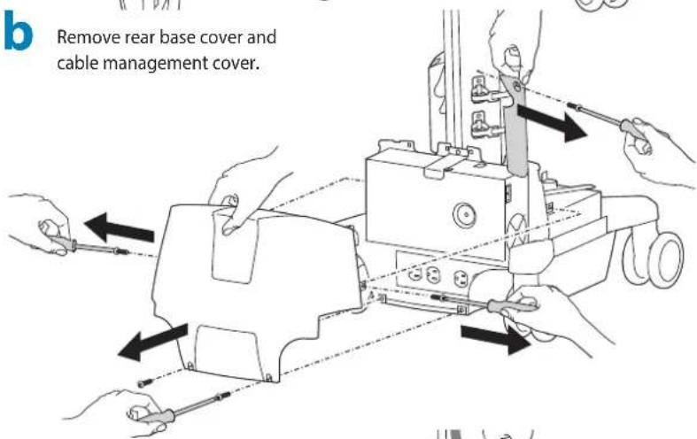
text_image
b Remove rear base cover and cable management cover.C
Route drawer power cable down into base and connect to power system.
text_image
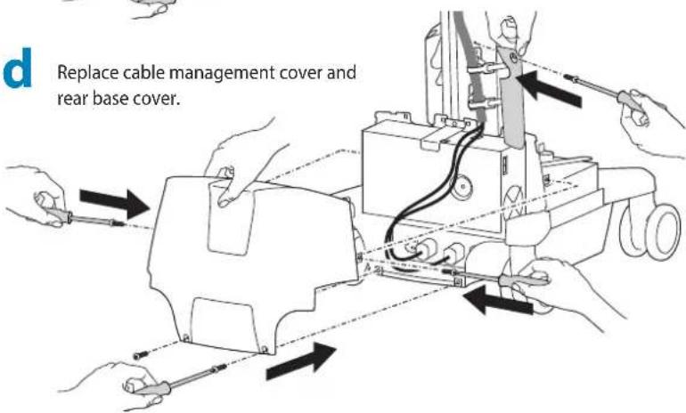
Replace cable management cover and rear base cover.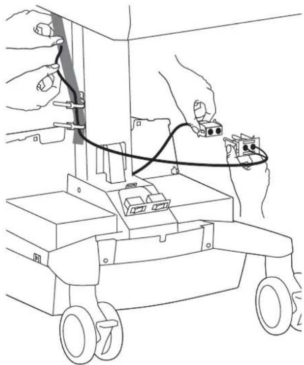
natural_image
Line drawing of hands connecting a cable to a small electronic device with wiring (no text or symbols)e
Replace front base cover.
natural_image
Line drawing of a toy car with a hand pressing a button, showing no text or symbols
natural_image
Diagram of a robotic vehicle with hands operating the engine compartment, showing motion arrows (no text or symbols)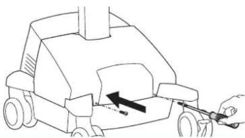
natural_image
Line drawing of a car with a hand pulling a tool, showing motion direction (no text or symbols)9
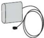
How To Attach Battery Pack for Non-Powered Carts Only


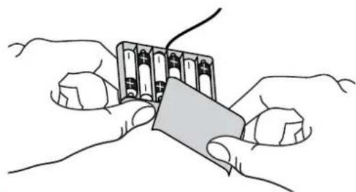
WARNING! Only use NiMh rechargeable batteries. Using any other types of batteries may cause them to leak, rupture, or explode causing personal injury or equipment damage.
a Make sure all 6 batteries are in the drawer battery pack, then peel off the adhesive backing.
natural_image
Illustration of two hands holding a battery pack with a paper clip (no text or symbols)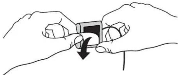
natural_image
Illustration of two hands holding a small object with a black arrow indicating rotation (no text or symbols)b Attach battery pack in storage area.

natural_image
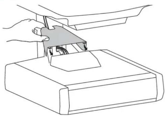
Line drawing of a hand operating a small component above a mechanical device (no text or symbols)C Route cable down through the bottom of the storage area and plug into the drawer controller.

flowchart
graph TD
    A["Device 1"] --> B["Switch"]
    B --> C["Port Layout"]
    C --> D["Server Interface"]
    D --> E["Arrow pointing to Port Layout"]
    style A fill:#f9f,stroke:#333
    style E fill:#bbf,stroke:#333
10
Replace top cover on drawer.
natural_image
Line drawing of hands using a tool to lift a device into a base (no text or symbols)
natural_image
Line drawing of a hand pressing down on a mechanical component with an arrow indicating force (no text or symbols)11
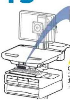
Replace worksurface.

text_image
Diagram illustrating how to adjust key keys from a printer, showing step-by-step assembly and lock mechanism.or
LCD CartsLaptop Carts
natural_image
Line drawing of a hand pressing a button on a device panel (no text or symbols)12 Adjustment
It is important that you adjust this product according to the weight of the mounted equipment as described in the following steps. Any time equipment is added or removed from this product, resulting in a change in the weight of the mounted load, you should repeat these adjustment steps to ensure safe and optimum operation.
Adjustments should move smoothly and easily through the full range of motion and stay where you set it. If adjustments are difficult and do not stay in the desired position, follow the instructions to loosen or tighten the tension to create a smooth, easy adjustment motion. Depending on your product and the adjustment, it may take several turns to notice a difference.

text_image
Lift – Up and down Release Brake to move riser.
Follow these instructions to tighten or loosen tension.

text_image
14mm (9/16") NOTE: Adjustment may require 40 - 60 revolutions.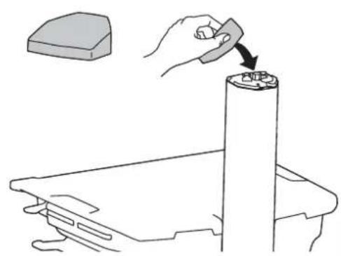
natural_image
Line drawing of a hand using a tool to press or install a cylindrical component, with no visible text or symbols.13
1x
NOTE: User should change Master Personal Identifi cation Number (PIN) upon receipt of cart.
Ensure that the main power system batteries are installed and functioning. The power does not need to be turned on at the power system user interface.
Lost Master PIN
Contact Ergotron Customer Care for instructions.
All PINs may vary in length from 4 – 7 digits. Number of PINs possible:
- Carts using StyleLink will store up to 1,000 PINs on the cart
- Carts not using StyleLink will store up to 100 PINs on the cart
- Ergotron recommends the following for choosing PIN digit length (assumes less than 1 in 25 chance of guessing random User PIN):
Max number of User PINs >50, 5+digit length recommended
Max number of User PINs >300, 6+digit length recommended
For maximum security use PIN length of 7
natural_image
Line drawing of a desktop computer with monitor and keyboard (no text or symbols)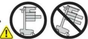
text_image
Safety warning symbols for road signs, one with a stop sign and another without a stop sign, both circled in black.CAUTION: Close worksurface before opening drawers. Open only one drawer at a time. Do Not push cart when drawers or worksurface are open. Failure to follow these instructions may cause the cart to be unstable.
Set-up Master PIN for the First Time (Default Master PIN: 12345)
Contact Ergotron Customer Care for instructions if Master PIN is lost.
- Enter default Master PIN (1-2-3-4-5) then press ENTER.
- Press 5 for Master PIN Entry mode
- Enter new Master PIN and press Enter (LEDs will blink green if PIN is accepted)
- Master PIN entry mode will exit after 5 seconds of inactivity (LEDs blink red twice)
Master PIN Mode Menu
Enter Master PIN and then select one of the below numbers to enter that mode
- User PIN Entry Mode
- Pharmacy PIN Entry/Change Mode
- Master Pin Change Mode
Programming User PINS
- Enter Master PIN and press ENTER for Mode Menu.
- Press 1 for User PIN Entry Mode.
- Input new User PIN and press ENTER (All LEDs blink green if PIN is accepted). You may enter multiple USER PINs consecutively.
- User PIN entry mode will exit after 5 seconds of inactivity (LEDs blink red twice).
NOTE: User PIN cannot be the same as a Master PIN or Pharmacy PIN. Once maximum User PIN storage is exceeded, the oldest User PIN will be over written.
Programming Pharmacy PIN
- Enter Master PIN and press ENTER for Mode Menu
- Press 2 for Pharmacy PIN Entry Mode
- Input Pharmacy PIN and press ENTER (all LEDs blink green in PIN is accepted).
- Pharmacy PIN entry mode will exit after 5 seconds of inactivity (LEDs blink red twice).
Note: System will hold 1 Pharmacy PIN. Pharmacy PIN allows all drawers to unlock at the same time. Drawers should then be opened at least slightly as the system will auto-lock after 10 seconds. All LEDs will flash green until system auto-locks. Once a drawer is opened the corresponding LED for that row will light solid until it is placed back into its original location.
Unlock Drawer (2 methods): NOTE: All Drawers in row must be closed before a new row can be unlocked.
- Enter User PIN (only numbers for available drawer rows flash green), then press desired drawer row number*.
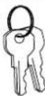
• Key - turn clockwise 1/4 turn
*Drawer Row Numbers:


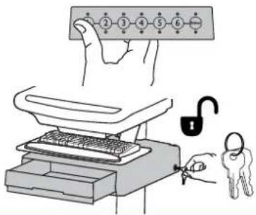
text_image
Illustration showing a hand holding a numbered list with an open key and lock mechanism, alongside a sketch of a keyboard and key.Lock Drawer:
- Wait 4 seconds for lock to engage automatically.
NOTE: Always ensure drawer is pushed in all the way and engaged with lock.
Drawer Troubleshooting
- No LEDs on keypad when pressing any number:
- Verify DC cable is connected from cart battery harness to controller.
- Verify keypad cable is connected to controller.
- Verify circuit breakers are not tripped and 5A fuse is installed in battery harness.
- Drawer selection not available when User PIN is entered:
- Check to make sure drawer cable is installed securely.
- Remove power from drawer system for 10 seconds and re-apply.
• LEDs flash red/green after User PIN in entered:
- Battery charge is low, check to make sure USB charging cable is plugged into computer and computer is ON.
LEDs/Alarm Meaning:
1,2,3,4, or 5 LED ON green: Corresponding Drawer is open.
1,2,3,4, or 5 LED flashing red and alarm sounding: Corresponding Drawer is open longer than 20 seconds. Mute alarm by pressing flashing button corresponding to open drawer.
All available drawer numbers flashing green: Waiting for drawer selection (see Unlock Drawer).
All LEDs flashing green: Pharmacy mode, all drawers are unlocked.
All LEDs blink red twice: PIN entry rejected/exit current mode after 5 seconds timeout.
All LEDs blink green 3 times: PIN entry accepted.
All LEDs flashing red: Firmware update in progress.
All LEDs flashing red/green: System power ON or low battery condition.