MGate EIP3270I-T - Gangway Moxa - Free user manual and instructions
Find the device manual for free MGate EIP3270I-T Moxa in PDF.

User questions about MGate EIP3270I-T Moxa
0 question about this device. Answer the ones you know or ask your own.
Ask a new question about this device
Download the instructions for your Gangway in PDF format for free! Find your manual MGate EIP3270I-T - Moxa and take your electronic device back in hand. On this page are published all the documents necessary for the use of your device. MGate EIP3270I-T by Moxa.
USER MANUAL MGate EIP3270I-T Moxa
First Edition, June 2009
www.moxa.com/product
MOXA®
© 2009 Moxa Inc. All rights reserved. Reproduction without permission is prohibited.
MGate EIP3000 DF1 to EtherNet/IP Gateway User's Manual
The software described in this manual is furnished under a license agreement and may be used only in accordance with the terms of that agreement.
Copyright Notice
Copyright © 2009 Moxa Inc.
All rights reserved.
Reproduction without permission is prohibited.
Trademarks
MOXA is a registered trademark of Moxa Inc.
All other trademarks or registered marks in this manual belong to their respective manufacturers.
Disclaimer
Information in this document is subject to change without notice and does not represent a commitment on the part of Moxa.
Moxa provides this document “as is,” without warranty of any kind, either expressed or implied, including, but not limited to, its particular purpose. Moxa reserves the right to make improvements and/or changes to this manual, or to the products and/or the programs described in this manual, at any time.
Information provided in this manual is intended to be accurate and reliable. However, Moxa assumes no responsibility for its use, or for any infringements on the rights of third parties that may result from its use.
This product might include unintentional technical or typographical errors. Changes are periodically made to the information herein to correct such errors, and these changes are incorporated into new editions of the publication.
Technical Support Contact Information
www.moxa.com/support
Moxa Americas:
Toll-free: 1-888-669-2872
Tel: +1-714-528-6777
Fax: +1-714-528-6778
Moxa China (Shanghai office):
Toll-free: 800-820-5036
Tel: +86-21-5258-9955
Fax: +86-10-6872-3958
Moxa Europe:
Tel: +49-89-3 70 03 99-0
Fax: +49-89-3 70 03 99-99
Moxa Asia-Pacific:
Chapter 1 Introduction....1-1
Overview 1-2
Package Checklist.... 1-2
Product Features 1-3
Chapter 2 Getting Started ....2-1
Connecting Power 2-2
Connecting Serial Devices.... 2-2
Connecting to a Host or the Network 2-2
Installing the Software.... 2-3
Mounting the Unit 2-3
Chapter 3 Hardware: EIP3170, EIP3170I 3-1
Panel Layout.... 3-2
LED Indicators 3-2
Dimensions....3-3
Jumpers.... 3-4
Pin Assignments 3-5
DB9 (Male) 3-5
Terminal Block (RS-422) 3-5
Power Input, Relay Output 3-6
DIN-Rail, Wall Mounting 3-6
Specifications 3-7
Chapter 4 Hardware: EIP3270, EIP3270I 4-1
Panel Layout.... 4-2
LED Indicators 4-2
Dimensions 4-3
Jumpers....4-4
Pin Assignments 4-5
DB9 (Male) 4-5
Power Input, Relay Output 4-5
DIN-Rail, Wall Mounting 4-6
Specifications 4-7
Chapter 5 Configuring the EtherNet/IP Gateway ....5-1
Installing the Software.... 5-2
Starting MGate Manager 5-6
Change Language Setting 5-6
Connecting to the Unit....5-7
Broadcast Search 5-7
Specify by IP Address 5-8
Modifying the Configuration.... 5-9
Configure IP Address and Other Network Settings.... 5-10
Configure Serial Communication Parameters 5-12
Set up Routing and ProCOM function.... 5-13
Set up Protocol.... 5-15
Set Up Miscellaneous 5-16
Verifying Location of Unit 5-17
Monitoring EtherNet/IP Activity 5-17
Open Traffic Monitor Window.... 5-18
Filter Traffic Information 5-19
Save Log to File....5-20
Upgrading Firmware 5-20
Chapter 6 Pin Assignments....6-1
DB9 (Male)....6-2
Terminal Block (RS-422) 6-3
Power Input, Relay Output 6-3
Welcome to the MGate EIP3000 line of DF1 to EtherNet/IP gateways. All models feature easy protocol conversion from DF1 to EtherNet/IP, and RS-232/422 ports for DF1 communication. One-port and two-port models are available.
This chapter is an introduction to the MGate EIP3000 and includes the following sections:
Overview
□ Package Checklist
□ Product Features
Overview
The MGate EIP3000 is a line of protocol gateways that provides users with
- protocol conversion between DF1 and EtherNet/IP
• virtual serial port for multiple DF1 and EtherNet/IP device communications - Windows utilities for easy setup and traffic monitoring.
Protocol conversion between DF1 and EtherNet/IP
MGate ^™ EIP3000 series products can be used to connect DF1 devices and EtherNet/IP devices to provide Allen Bradley PLCs with remote maintenance capability. By supporting PCCC objects on CIP, the MGate ^™ EIP3000 can communicate seamlessly with Rockwell Ethernet devices. The EIP3000 protocol gateways come with either 1 or 2 serial ports to allow users to select a suitable gateway depending on the size of the network.
ProCOM function for multiple DF1 and EtherNet/IP device communications
Each MGate™ EIP3000 gateway supports a virtual serial port. A remote PC uses a Moxa-provided ProCOM function to connect to the EIP3000's virtual serial port. RSLinx and SCADA systems can use the virtual COM port to communicate with an EIP3000 gateway. The virtual serial port function gives RSLinx or some SCADA systems the capability to connect to multiple DF1 and EtherNet/IP devices through a protocol gateway.
Windows utilities for easy setup and traffic monitoring
A Windows utility is provided to make configuration and operation of the MGate EIP3000 as easy as possible. The utility automatically connects to all available MGate EIP3000 units on the LAN for you. Traffic monitoring functions help you troubleshoot the communication problems between DF1 and EtherNet/IP protocols by tracking items such as connection status and address translation errors.
Package Checklist
All models in the MGate EIP3000 line are shipped with the following items:
Standard Accessories
• 1 MGate EIP3000 DF1 to EtherNet/IP gateway.
- Document & software CD.
- Quick Installation Guide.
• Product warranty statement.
Optional Accessories
- DR-4524: 45W/2A DIN-rail 24 VDC power supply with universal 85 to 264 VAC input.
- DR-75-24: 75W/3.2A DIN-rail 24 VDC power supply with universal 85 to 264 VAC input.
- DR-120-24: 120W/5A DIN-rail 24 VDC power supply with 88 to 132 VAC/176 to 264 VAC input by switch.
NOTE: Notify your sales representative if any of the above items is missing or damaged.
Product Features
- PCCC objects for Rockwell Automation networks supported.
- 8 simultaneous EtherNet/IP clients with up to 16 simultaneous requests per client.
- Serial redirector function provided.
- ProCOM function provides virtual serial port for multiple DF1 and EtherNet/IP device communication.
- Embedded EtherNet/IP and DF1 protocol analyzer.
- Redundant dual DC power inputs.
• Built-in Ethernet cascading for easy wiring. - Configuration over Ethernet with easy-to-use Windows utility.
- Software-selectable RS-232/422 communication.
This chapter provides basic instructions for installing the MGate EIP3000.
The following topics are covered:
□ Connecting Power
□ Connecting Serial Devices
□ Connecting to a Host or the Network
□ Installing the Software
□ Mounting the Unit
Connecting Power
The unit can be powered using the AC adaptor or by connecting a power source to the terminal block, depending on the model. The following instructions are for the AC adaptor:
- Plug the connector of the power adapter into the DC-IN jack on the back of the unit.
- Plug the power adapter into an electrical outlet.
- Follow these instructions to connect a power source to the terminal block:
- Loosen or remove the screws on the terminal block.
- Connect the 12–48 VDC power line to the terminal block.
- Tighten the connections using the screws on the terminal block.
Note that the unit does not have an on/off switch. It automatically turns on when it receives power. The PWR LED on the top panel will glow to indicate that the unit is receiving power.
For power terminal block pin assignments, please refer to the hardware reference chapter for your model.
Connecting Serial Devices
The unit's serial port(s) are located on the back panel. There are two options for connecting serial devices, depending on the serial interface:
- You may use a DB9-to-DB9 cable to connect a serial device to the unit. Plug one end of the cable into the port on the unit's back panel and plug the other end of the cable into the device's serial port.
- You may make your own customized serial cable to connect a serial device to the unit. For the pin assignments of the unit's serial port, please refer to Chapter 6. This information can then be used to construct your own serial cable.
For serial port pin assignments, please refer to the hardware reference chapter for your model.
Connecting to a Host or the Network
A 10/100BaseT Ethernet port is located on the unit's front panel. This port is used for the unit's connection to a host or Ethernet network, as follows:
- For normal operation, use a standard straight-through Ethernet cable to connect the unit to your EtherNet/IP network.
- For initial configuration or for troubleshooting purposes, you may connect the unit directly to a PC. In this case, use a crossover Ethernet cable to connect the unit to your PC's Ethernet connector.
The unit's Link LED will light up to indicate a live Ethernet connection.
One Ethernet port can be used to connect to the network, and the other port can be used to connect to another Ethernet device.
Installing the Software
The Windows management utility is installed from the Document and Software CD. Follow the onscreen instructions after inserting the CD.
Mounting the Unit
The unit can be mounted on the wall or mounted on a DIN-Rail.
This chapter provides hardware information for the MGate EIP3170 and EIP3170I.
The following topics are covered:
Panel Layout
□ LED Indicators
Dimensions
□ Jumpers
☐ Pin Assignments
DB9 (Male)
Terminal Block (RS-422)
▶ Power Input, Relay Output
☐ DIN-Rail, Wall Mounting
Specifications
Panel Layout
LED Indicators
| Name Color | Function | |
| PWR1 Red | Power is being supplied to the power input. | |
| PWR2 Red | Power is being supplied to the power input. | |
| RDY | Red | Steady on: Power is on and unit is booting up.Blinking: Indicates an IP conflict, or DHCP or BOOTP server is not responding properly. |
| Green | Steady on: Power is on and unit is functioning normally.Blinking: Unit is responding to software Locate function. | |
| Off Power is off, or power error condition exists. | ||
| Ethernet | Orange 10 Mbps Ethernet connection. | |
| Green 100 Mbps Ethernet connection. | ||
| Off Ethernet cable is disconnected, or has a short. | ||
| P1 | Orange Serial port is receiving data. | |
| Green Serial port is transmitting data. | ||
| Off | No data is being transmitted or received through the serial port. | |
Dimensions
Jumpers
The DIP switches are located beneath the DIP switch panel on the side of the unit.
To add a 120 Ω termination resistor, set switch 3 to ON; set switch 3 to OFF (the default setting) to disable the termination resistor.
To set the pull high/low resistors to 150 KΩ, set switches 1 and 2 to OFF. This is the default setting.
To set the pull high/low resistors to 1 KΩ, set switches 1 and 2 to ON.
Switch 4 on the port's assigned DIP switch is reserved.

ATTENTION
Do not use the 1 KΩ pull high/low setting on the MGate EIP3000 when using the RS-232 interface. Doing so will degrade the RS-232 signals and reduce the effective communication distance.
Pin Assignments
DB9 (Male)
The MGate EIP3170 and EIP3170I use a DB9 (male) serial port for RS-232 connections to DF1 devices.
| Pin RS-232 | |
| 1 | DCD |
| 2 | RxD |
| 3 | TxD |
| 4 | DTR |
| 5 | GND |
| 6 | DSR |
| 7 | RTS |
| 8 | CTS |
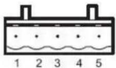
Terminal Block (RS-422)
The MGate EIP3170 and EIP3170I use a terminal block connector for RS-422 connections to DF1 devices.
| Pin | RS-422RS-485 (4W) |
| 1 | TxD+ |
| 2 | TxD- |
| 3 | RxD+ |
| 4 | RxD- |
| 5 | GND |
Power Input, Relay Output

| V2+ | V2- | V1+ | V1- | |||
| Shielded Ground | DC Power Input 1 | DC Power Input 1 | Relay Output | Relay Output | DC Power Input 2 | DC Power Input 2 |
DIN-Rail, Wall Mounting
There are two sliders on the back of the unit for DIN-Rail and wall mounting.
Mounting on a DIN-Rail: Pull out the bottom slider; latch the unit onto the DIN-Rail, and push the slider back in.
natural_image
Technical line drawings of a mechanical component with multiple views and mounting features (no text or symbols)Mounting on the wall: Pull out both the top and bottom sliders and align the screws accordingly.
natural_image
Two technical line drawings of rectangular components with directional arrows indicating movement or force (no text or symbols)Specifications
LAN
Ethernet 10/100 Mbps, RJ45, Auto MDI/MDIX
Protection Built-in 1.5 KV magnetic isolation
Serial Interface
Interface RS-232/422
No. of Ports 1 port
Connector Type DB9 (male) for RS-232, terminal block for RS-422
RS-232: TxD, RxD, RTS, CTS, DTR, DSR, DCD, GND Signals
RS-422: Tx+, Tx-, Rx+, Rx-, GND
Serial Line Protection 15 KV ESD for all signals
Serial Communication parameters
Parity None, Even, Odd
Data Bits 8
Stop Bits 1, 2
Flow Control RTS/CTS, DTR/DSR
Transmission Speed 1200 bps to 921.6 Kbps
Software Features
Utilities MGate Manager
Multi-Request 8 simultaneous EtherNet/IP clients with up to 16 simultaneous requests per client
Protocol Ethernet: CIP (PCCC) on EtherNet/IP
Power Input 12 to 48 VDC
Power Socket Terminal block
Power Consumption EIP3170: 435 mA@12 VDC, 130 mA@48 VDC
EIP3170I: 555 mA@12 VDC, 140 mA@48 VDC
Environment
Operating Temperature 0 to 55°C (32 to 13 1°F), 5 to 95%RH
-40 to 75°C (-40 to 167°F), 5 to 95%RH for “-T” models
Storage Temperature -20 to 85°C (-4 to 185°F), 5 to 95% RH
Warranty 5 years
This chapter provides hardware information for the MGate EIP3270 and EIP3270I.
The following topics are covered:
Panel Layout
□ LED Indicators
Dimensions
□ Jumpers
☐ Pin Assignments
DB9 (Male)
Power Input, Relay Output
☐ DIN-Rail, Wall Mounting
Specifications
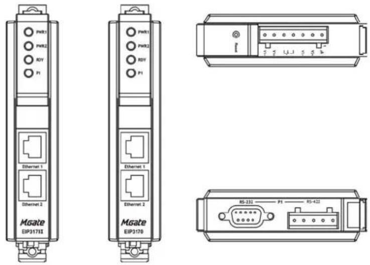
Panel Layout

LED Indicators
| Name Color | Function | |
| PWR1 | Red | Power is being supplied to the power input. |
| PWR2 | Red | Power is being supplied to the power input. |
| RDY | Red | Steady on: Power is on and unit is booting up.Blinking: Indicates an IP conflict, or DHCP or BOOTP server is not responding properly. |
| Green | Steady on: Power is on and unit is functioning normally.Blinking: Unit is responding to software Locate function. | |
| Off | Power is off, or power error condition exists. | |
| Ethernet | Orange | 10 Mbps Ethernet connection. |
| Green | 100 Mbps Ethernet connection. | |
| Off | Ethernet cable is disconnected, or has a short. | |
| P1, P2 | Orange | Serial port is receiving data. |
| Green | Serial port is transmitting data. | |
| Off | No data is being transmitted or received through the serial port. |
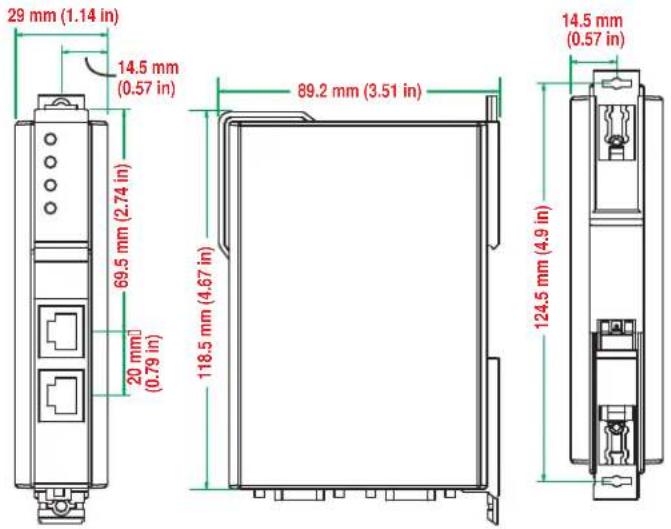
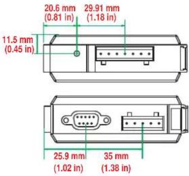
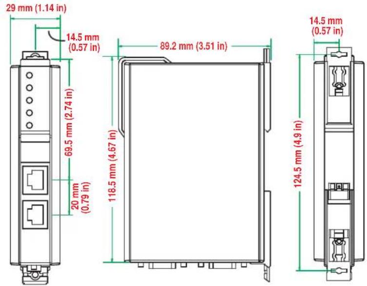
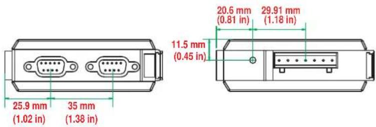
Dimensions
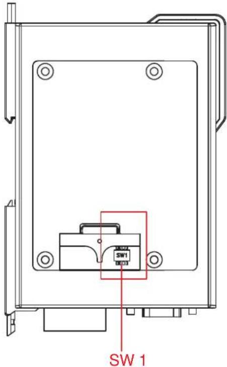
Jumpers
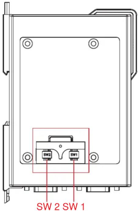
The DIP switches are located beneath the DIP switch panel on the side of the unit.
To add a 120 Ω termination resistor, set switch 3 on the port's assigned DIP switch to ON; set switch 3 to OFF (the default setting) to disable the termination resistor.
To set the pull high/low resistors to 150K , set switches 1 and 2 on the port's assigned DIP switch to OFF. This is the default setting.
To set the pull high/low resistors to 1 KΩ, set switches 1 and 2 on the port's assigned DIP switch to ON.
Switch 4 on the port's assigned DIP switch is reserved.

ATTENTION
Do not use the 1 KΩ pull high/low setting on the MGate EIP3000 when using the RS-232 interface. Doing so will degrade the RS-232 signals and reduce the effective communication distance.
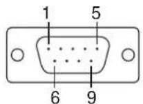
Pin Assignments
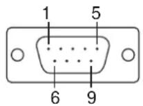
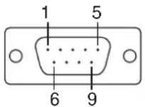
DB9 (Male)
The MGate EIP3000 uses DB9 (male) serial ports to connect Modbus RTU or ASCII devices. Each port supports two serial interfaces: RS-232 and RS-422.
| Pin RS-232 RS-422 | ||
| 1 | DCD | TxD- |
| 2 | RxD | TxD+ |
| 3 | TxD | RxD+ |
| 4 | DTR | RxD- |
| 5 | GND | GND |
| 6 | DSR | --- |
| 7 | RTS | --- |
| 8 | CTS | --- |
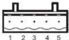
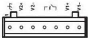
Power Input, Relay Output
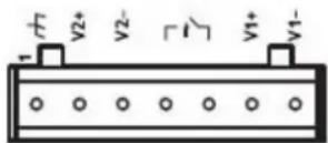
| V2+ | V2- | V1+ | V1- | |||
| Shielded Ground | DC Power Input 1 | DC Power Input 1 | Relay Output | Relay Output | DC Power Input 2 | DC Power Input 2 |
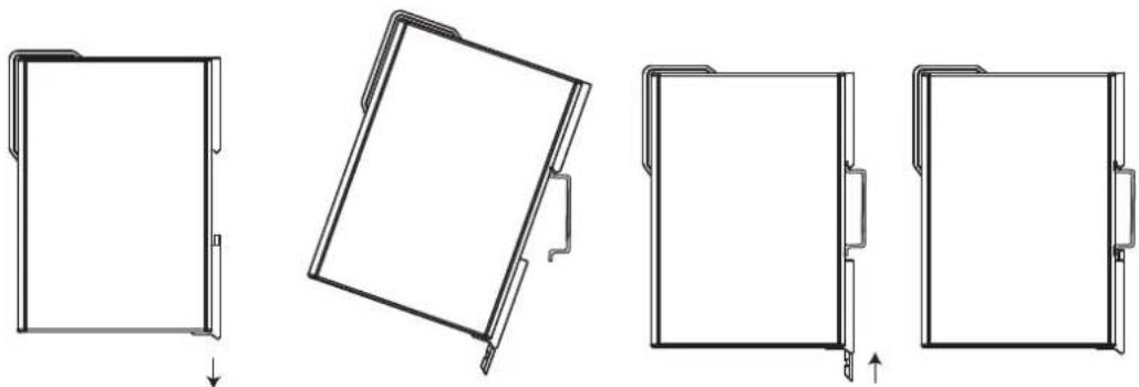
DIN-Rail, Wall Mounting
There are two sliders on the back of the unit for DIN-Rail and wall mounting.
Mounting on a DIN-Rail: Pull out the bottom slider; latch the unit onto the DIN-Rail, and push the slider back in.
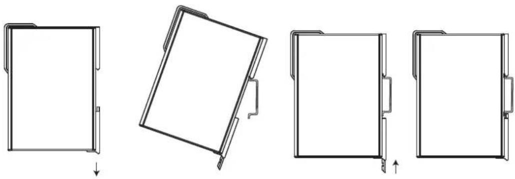
natural_image
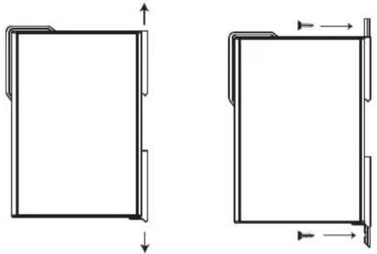
Technical line drawings of a folding panel with arrows indicating assembly or movement (no text or symbols)Mounting on the wall: Pull out both the top and bottom sliders and align the screws accordingly.
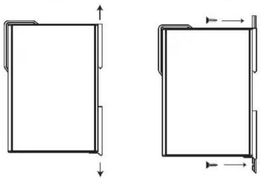
natural_image
Two technical line drawings of a rectangular frame with internal supports and dimension arrows (no text or symbols)Specifications
LAN
Ethernet 10/100 Mbps, RJ45, Auto MDI/MDIX
Protection Built-in 1.5 KV magnetic isolation
Serial Interface
Interface RS-232/422
No. of Ports 2 ports
Connector Type DB9 (male)
RS-232: TxD, RxD, RTS, CTS, DTR, DSR, DCD, GND Signals
RS-422: Tx+, Tx-, Rx+, Rx-, GND
Serial Line Protection 15 KV ESD for all signals
Serial Communication Parameters
Parity None, Even, Odd
Data Bits 8
Stop Bits 1, 2
Flow Control RTS/CTS, DTR/DSR
Transmission Speed 1200 bps to 921.6 Kbps
Software Features
Utilities MGate Manager
Multi-Request 8 simultaneous EtherNet/IP clients with up to 16 simultaneous requests per client
Protocol Ethernet: CIP (PCCC) on EtherNet/IP
Power Input 12 to 48 VDC
Power Socket Terminal block
Power Consumption EIP3270: 435 mA@12 VDC, 145 mA@48 VDC
EIP3270I: 510 mA@12 VDC, 150 mA@48 VDC
Environment
Operating Temperature 0 to 55°C (32 to 13 1°F), 5 to 95%RH
-40 to 75°C (-40 to 167°F), 5 to 95%RH for advanced models with “-T” option
Storage Temperature -20 to 85°C (-4 to 185°F), 5 to 95% RH
Warranty 5 years
Configuring the EtherNet/IP Gateway
We discuss the following topics in this chapter:
□ Installing the Software
□ Starting MGate Manager
➢ Change Language Setting
□ Connecting to the Unit
▶ Broadcast Search
➢ Specify by IP Address
□ Modifying the Configur ation
Configure IP Address and Other Network Settings
➢ Configure Serial Communi cation Parameters
➢ Set up Routing and ProCOM function
➢ Set up Protocol
▶ Set Up Miscellaneous
□ Verifying Location of Unit
□ Monitoring EtherNet/IP A ctivity
▶ Open Traffic Monitor W indow
Filter Traffic Information
Save Log to File
□ Upgrading Firmware
Installing the Software
The following instructions explain how to install MGate Manager, a utility for configuring and monitoring MGate EIP3000 units over the network.
- Insert the Document and Software CD into the CD-ROM drive. Locate and run the following setup program to begin the installation process:
MGM_Setup_[Version]_Build_[DateTime].exe
The latest version might be named MGM_Setup_Ver1.3_Build_xxxxxxxx.exe, for example:

MGM_Setup_Ver1.3_Build_09040...
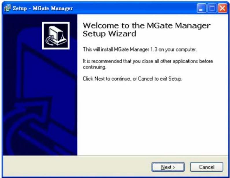
MGate Manager Setup
Moxa Inc.
- You will be greeted by the Welcome window. Click Next to continue.
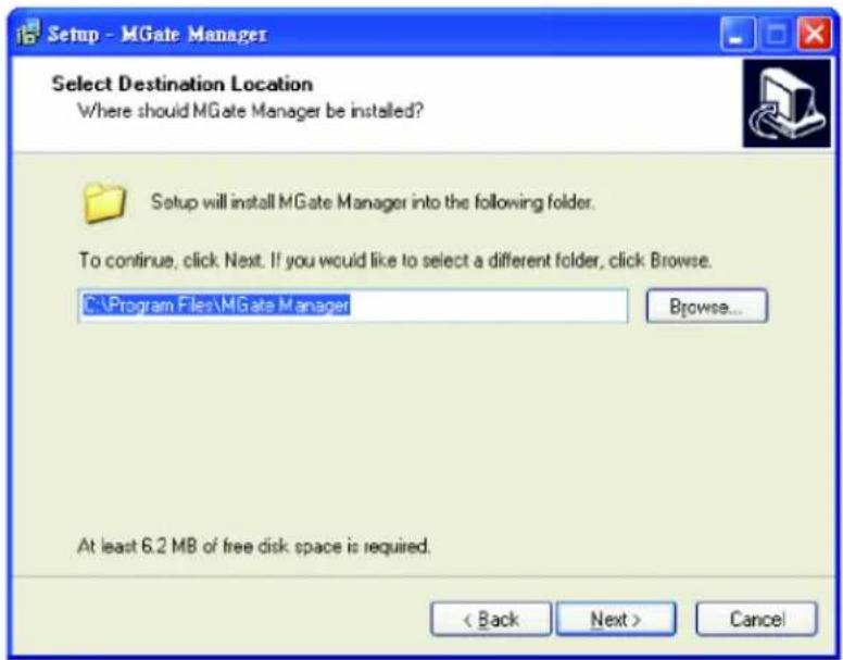
- When the Select Destination Location window appears, click Next to continue. You may change the destination directory by first clicking on Browse....
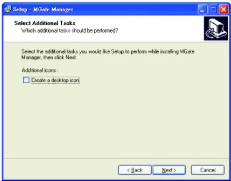
- When the Select Additional Tasks window appears, click Next to continue. You may select Create a desktop icon if you would like a shortcut to MGate Manager on your desktop.
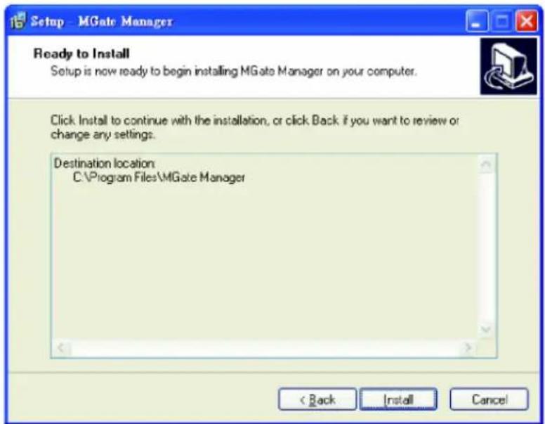
- Click Next to start copying the software files.
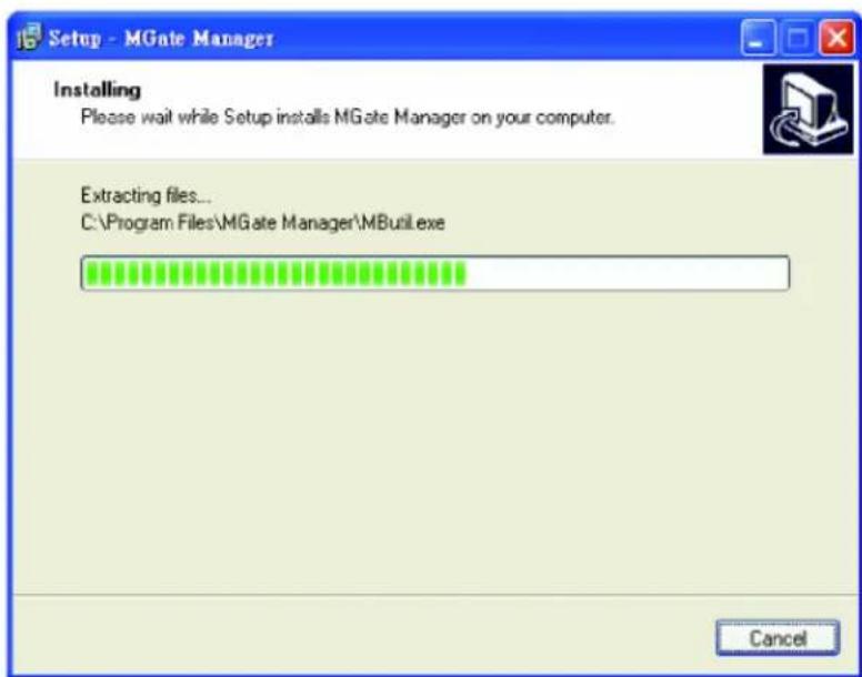
- A progress bar will appear. The procedure should take only a few seconds to complete.
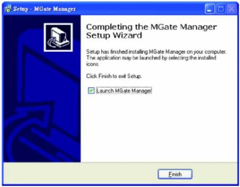
- A message will indicate that MGate Manager is successfully installed. You may choose to run it immediately by selecting Launch MGate Manager.
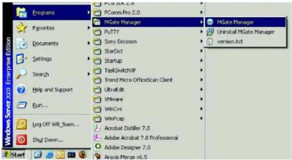
- You may also open MGate Manager through Start Programs MGate Manager MGate Manager, as shown below.
Starting MGate Manager
MGate Manager is a Windows-based utility that is used to configure the MGate EIP3000.
Before running MGate Manager, make sure that your PC and the MGate EIP3000 are connected to the same network. Alternatively, the MGate EIP3000 may be connected directly to the PC for configuration purposes. Please refer to Chapter 2 for more details.
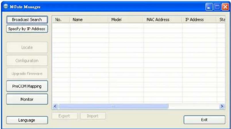
You may open MGate Manager from the Windows Start menu by clicking Start → Programs → MGate Manager → MGate Manager. The MGate Manager window should appear as shown below.
Change Language Setting
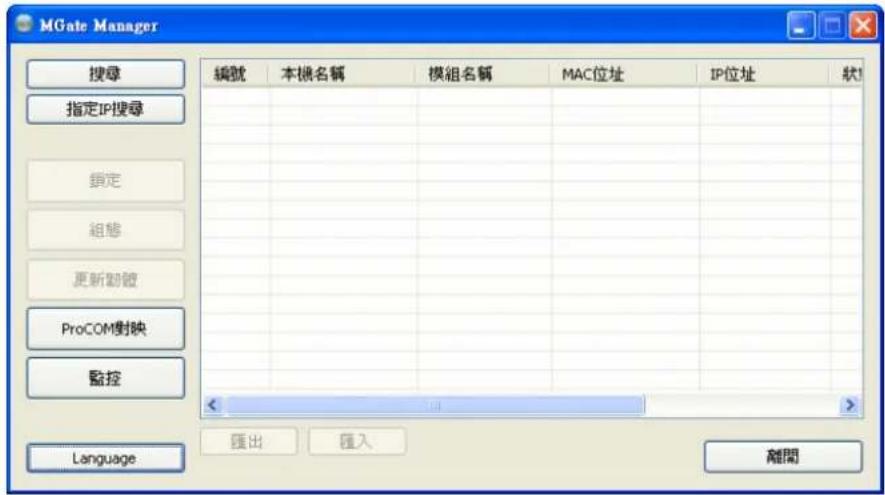
If you wish to run MGate Manager in a different language, you may click Language to change the language setting. A dialog box showing the available languages should appear as shown below.

When you click OK, MGate Manager will immediately reflect your chosen language.
Use "Default Language" before contacting Moxa Technical Support.
With support for multiple languages, MGate Manager is more user-friendly and accessible. However, if you need assistance from Moxa Technical Support, please change the language to "Default Language". This will prevent any misunderstandings or confusion about MGate Manager menu items and commands as our engineers assist you.
The default language is English and will only be active for the current MGate Manager session. When you open MGate Manager again, the language will revert to your original setting.
Connecting to the Unit
MGate Manager needs to connect to the unit before the unit can be configured. There are two methods to connect to the unit. Broadcast Search is used to find every MGate EIP3000 on the LAN. Search by IP attempts to connect to a specific unit by IP address, which is useful if the unit is located outside the LAN or can only be accessed by going through a router.
Broadcast Search
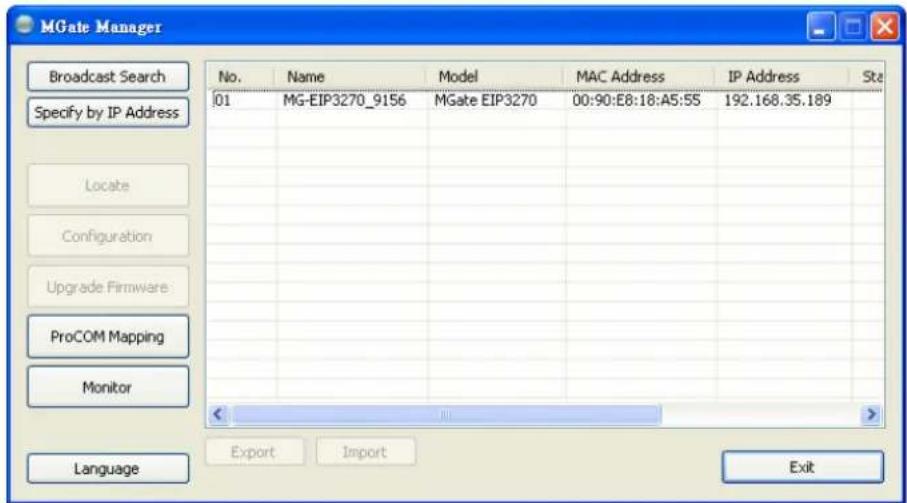
Click Broadcast Search to begin searching the LAN for all MGate EIP3000 units.
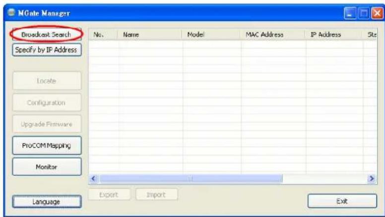
When the search is complete, every MGate EIP3000 that is found on the LAN will appear in the window with MAC address and IP address. Simply select the one that you wish to configure.
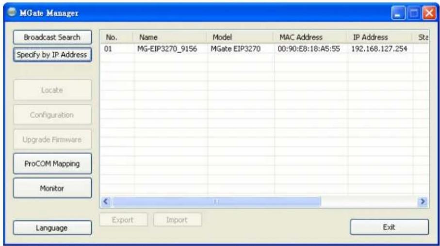
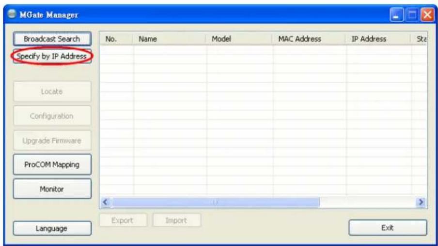
Specify by IP Address
Click Specify by IP Address if you know the IP address of the unit and wish to connect to it directly.
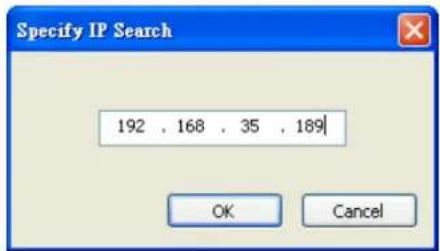
A dialog box will appear. Enter the unit's IP address and click OK.
If the search is successful, the unit will be listed in MGate Manager. Click the unit to begin configuration.

ATTENTION
If Search by IP Address fails to locate the MGate EIP3000, the IP address that you entered might be incorrect. Try doing the search again and re-entering the IP address carefully.
Another possibility is that the MGate EIP3000 is located on the same LAN as your PC, but on a different subnet. In this case, you can modify your PC's IP address and or netmask so that it is on the same subnet as the MGate EIP3000. After your PC and the MGate EIP3000 are on the same subnet, MGate Manager should be able to find the unit.
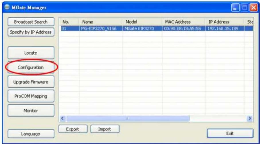
Modifying the Configuration
Once your unit is displayed in MGate Manager, select it by clicking on it. The Configuration button will become available. Click Configuration to open the configuration window.
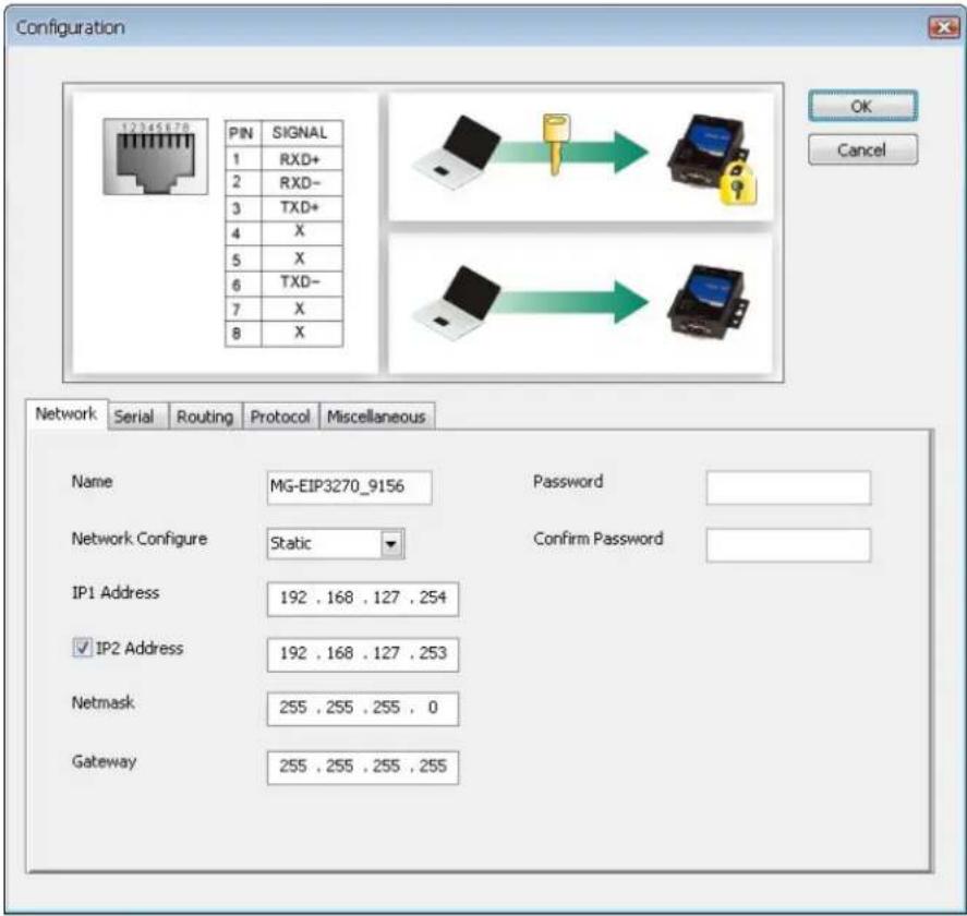
Configure IP Address and Other Network Settings
The Network tab is where the unit's network settings are configured. You can modify the Name, Network Configuration, IP1 Address, IP2 Address (only for 2-port model) and the default IP1 address is 192.168.127.254, IP2 address is 192.168.127.253, Netmask and Default Gateway. You may also select a Password to protect the unit from unauthorized access.
| Parameter Value Notes | ||
| Name (an alphanumeric string) | You can enter a name to help you identify the unit, such as the location, function, etc. | |
| Network Configuration | Static IP, DHCP, BootP, or DHCP/BootP | Select “Static IP” if you are using a fixed IP address. Select one of the other options if the IP address is set dynamically. |
| IP1 Address | 192.168.127.254(or other 32-bit number) | The IP (Internet Protocol) address identifies the server on the TCP/IP network. |
| IP2 Address | 192.168.127.253(or other 32-bit number) | The IP2 (Internet Protocol) address identifies the server on the TCP/IP network. |
| Netmask | 255.255.255.0(or other 32-bit number) | This identifies the server as belonging to a Class A, B, or C network. |
| Gateway | 255.255.255.255(or other 32-bit number) | This is the IP address of the router that provides network access outside the server’s LAN. |
| Password (an alphanumeric string) | You can set a password to prevent unauthorized users from configuring the unit. The password will be required when anyone attempts to configure the unit over the network. Modbus operation is not affected by the password. | |
| Confirm password (an alphanumeric string) | Re-type the password again for confirmation. | |

ATTENTION
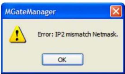
Both IP1 and IP2 all can be set manually. Since IP1 is the main IP address, please assign the IP2 address to the same network subnet as IP1. If IP2 is assigned a different network subnet from IP1, an error message will appear. To continue, click OK and set a valid IP address for IP2.
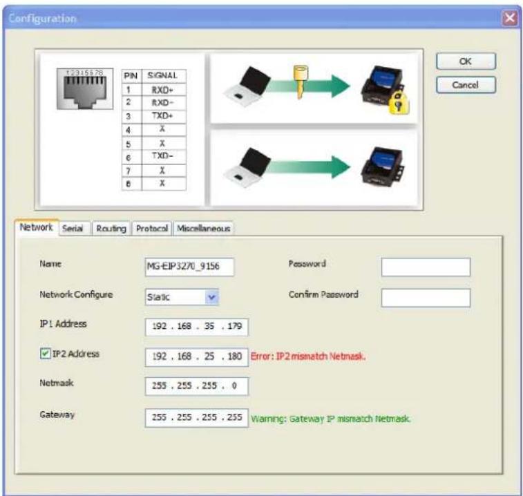
The Gateway will only display a warning message if the Gateway IP address is invalid. However, you can still click OK to continue.

ATTENTION
To erase an existing password, leave both the New Password and Confirm Password text input boxes blank. The password will be erased when you click OK in the bottom right corner.
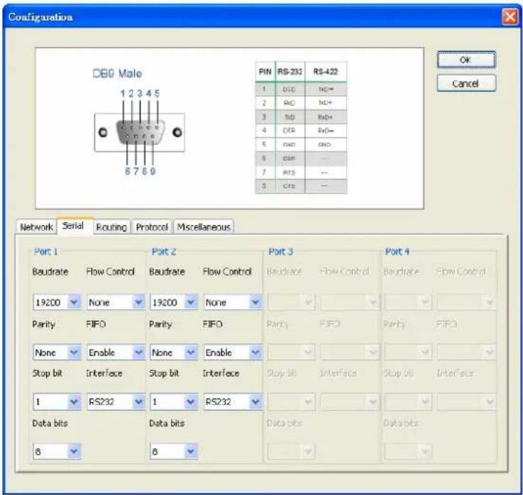
Configure Serial Communication Parameters
The Serial tab is where each serial port's communication parameters are configured. You can configure Baud Rate, Parity, Stop Bit, Flow Control, FIFO, and Interface Mode.
| Parameter Value | |
| Interface Mode | RS-232 |
| RS-422 | |
| Baud Rate 1200 bps to 961200 bps | |
| Parity | None, Odc |
| Stop Bits 1, 2 | |
| Flow Control None, DTR/DSR, RTS/CTS | |
| UART FIFO Enable, Disable | |
Even
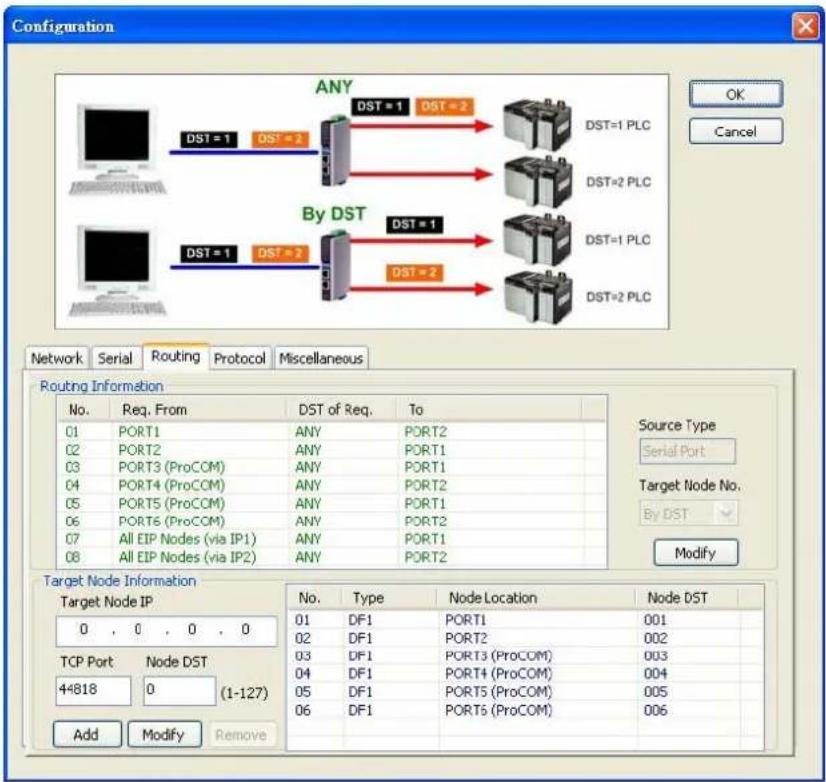
Set up Routing and ProCOM function
The definitions of the Routing tab determine how requests will be routed by the unit.
How to set Routing on the MGate EIP3000
The MGate EIP3000 decides where to forward the received requests according to its internal routing rules. The internal routing rules are set on the Routing page. Two kinds of routing rules can be used. The first one is forwarding each received request according to its DST. DST is the destination address of each request in PCCC protocol (DF1 application protocol). You must set up the DST of each target device first, so that the EIP3000 knows which target device to forward the request to. On the Routing page, this information is shown in the table on the bottom half of the page. In this table, the DF1 devices connected to EIP3000 (via serial port or ProCOM) are added automatically and assigned a default DST (EIP3170:PORT1=1, ProCOM =2, 3, 4, 5; EIP3270:PORT1=1, PORT2=2, ProCOM =3, 4, 5, 6). If you would like to connect to an EIP interface (EtherNet/IP) device, you must configure the relationship between “Node DST” and “Target Node IP” of the EIP interface device manually.
Another routing rule is static link, which ignores the DST and directly forwards all the requests sent from a specified source device to the defined target device. You can set the source device and target device mapping on the upper half of the page.
The complete routing table is shown on the upper half of the page. This table shows which rule (by DST or static link) is used on the requests from a specified source. The default setting for EIP3270 is static link of PORT1 to PORT2, PORT2 to PORT1, PORT3(ProCOM) to PORT1, PORT4(ProCOM) to PORT2, PORT5(ProCOM) to PORT1, PORT6(ProCOM) to PORT2 and all EIP devices connect from IP1 and forward to PORT1, and all EIP devices connect from IP2 and forward to PORT2. Of course, you could use the DST rule instead of the static link rule by changing the setting manually. Notice that the EIP device can only use the static link rule since there is no DST in the EIP requests.
What is ProCOM?
ProCOM is Moxa's proprietary function which provides a virtual COM port for flexible DF1 and EtherNet/IP communication. This is an intelligent function of the Fieldbus gateway that translates the data to the correct destination through DF1 protocol.
How to set ProCOM on the MGate EIP3000
ProCOM is your best solution if your system requires using a remote PC that only supports DF1 protocol to control remote DF1 devices. It requires that your PC have a virtual COM port that supports DF1 protocol to connect to the EIP3000 via the network. With ProCOM, the EIP3000 will treat the COM port on your PC as if it were an additional serial port on the EIP3000. Before using this powerful function, you must complete ProCOM mapping.
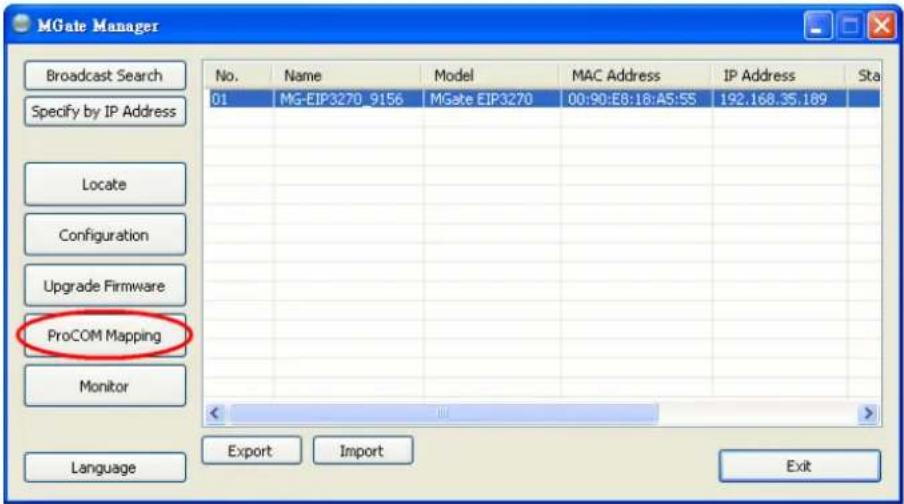
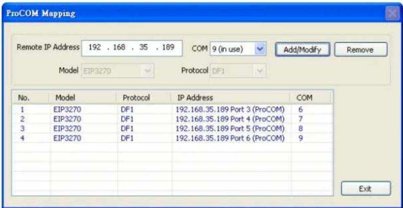
After finding the EIP3000 with the search function, select the EIP3000 device for which you want to set ProCOM for and then click ProCOM Mapping to enter the mapping page. Please refer to the above figures.
On the ProCOM mapping page, you can map up to 4 ProCOM functions to your PC's COM port. The driver will generate a virtual COM port on your PC and connect to the selected EIP3000 over the network. This means that when you send a DF1 request to ProCOM, the driver will forward your request to the EIP3000. Then the EIP3000 will forward your request to the target DF1 device according to the pre-set routing table. Similarly, when the EIP3000 receives the response from the
target DF1 device, it will forward the response to ProCOM and then the application running on your PC will receive the response.
Set up Protocol
![Configuration EtherNetIP DF1 PC (1) Response time (2) (3) (4) (5) ACK time (6) MGate EIP3000 PLG Network Serial Routing Protocol Miscellaneous Response Time-out Node Location Port 1 Port 2 ProCOM Ethernet Response Time-out 3000 (100-120000 ms) (Default: 3000 ms) DF1 Settings ACK Time-out 500 [50-30000 ms] (Default: 500 ms) (Recommended value: Response Time-out / 4) Frame Error Detection CRC16 BCC EIP Settings CIP Communications Connected (Class 3) Unconnected (UCMM)](/content/2026/06/1188940/images/443347e842c68b8fe7b0d8f4c54106061971aecf1ed03e8aae0655422110f3d1.jpg)
You can configure the options for DF1, EtherNet/IP, and CIP protocol. Response Time-out defines how much time the EIP3000 needs to wait for a response after sending a PCCC command to a DF1/EIP device. We strongly suggest that the value should be greater than ACK timeout, since it requires at least double the timeout values of DF1 ACK after the EIP3000 forwards a PCCC command and before it gets a response.
ACK timeout for DF1 settings defines how much time the EIP3000 needs to wait for an ACK after sending a DF1 message to a DF1 device. DF1 messaging supports CRC16 and BCC as the method of frame error checking.
The EIP settings define how to send a CIP message as the EIP3000 is an EIP client. The EIP3000 uses connected CIP messages as default. If your EIP device only supports unconnected messages, you can change this setting accordingly.
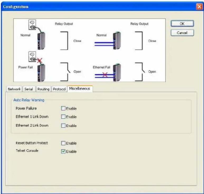
Set Up Miscellaneous
This page defines all other options that can not be classified. Currently, this page defines “Auto Relay Warning”, “Reset Button Protect” and “Telnet Console”. The auto relay warning includes power failure, Ethernet 1 or 2 links down to trigger relay warning. If any checked trigger condition occurs, the EIP3000 will open the circuit of the relay output and trigger the Fault LED to start blinking. Otherwise, the EIP3000 will short circuit the relay output.
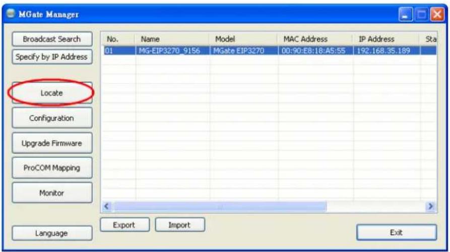
Verifying Location of Unit
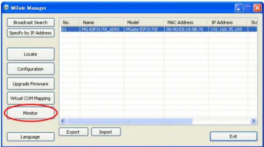
If you are managing multiple MGate units, you may wonder if you are configuring the correct unit in MGate Manager. You can select a unit in MGate Manager and click Locate to make that unit's "Ready" LED blink for a few seconds. This will tell you which physical unit corresponds with the unit that you selected.
Monitoring EtherNet/IP Activity
For troubleshooting or management purposes, you can monitor the data passing through any MGate EIP3000 on the network. Data events will be logged as they pass through the gateway. Rather than simply echoing the data, MGate Manager presents the data in an intelligent, easily-understood format, with clearly designated fields including source, type, destination, contents, and more. Events can be filtered in different ways, and the complete log can be saved to a file for later analysis.
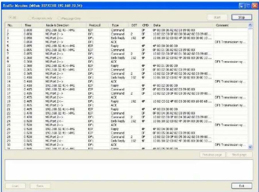
Open Traffic Monitor Window
Select the unit that you wish to monitor and click Monitor to open the Traffic Monitor window.
In the Traffic Monitor window, click Start to begin live monitoring of the data passing through the selected MGate EIP3000 unit.
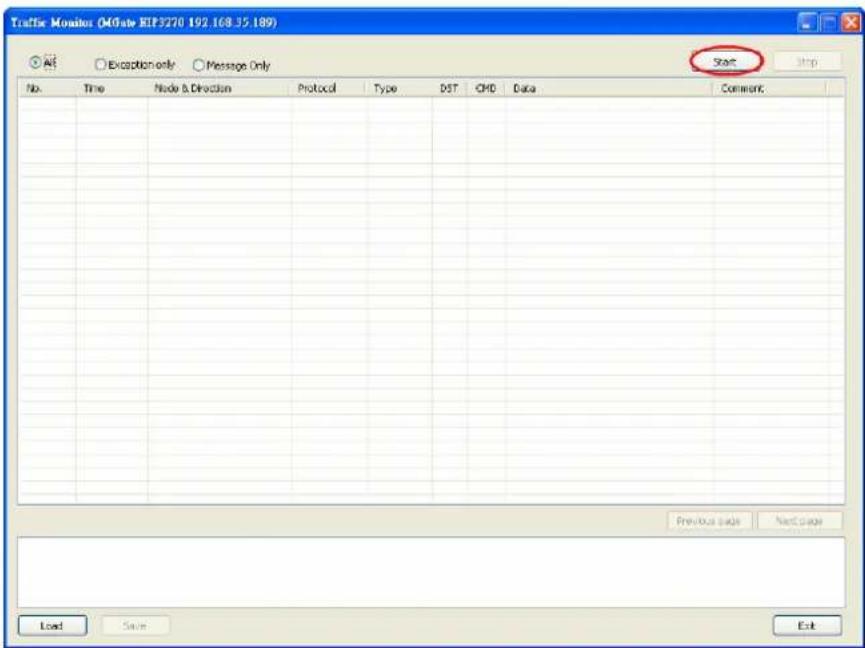
To stop capturing the log, press the Stop button.
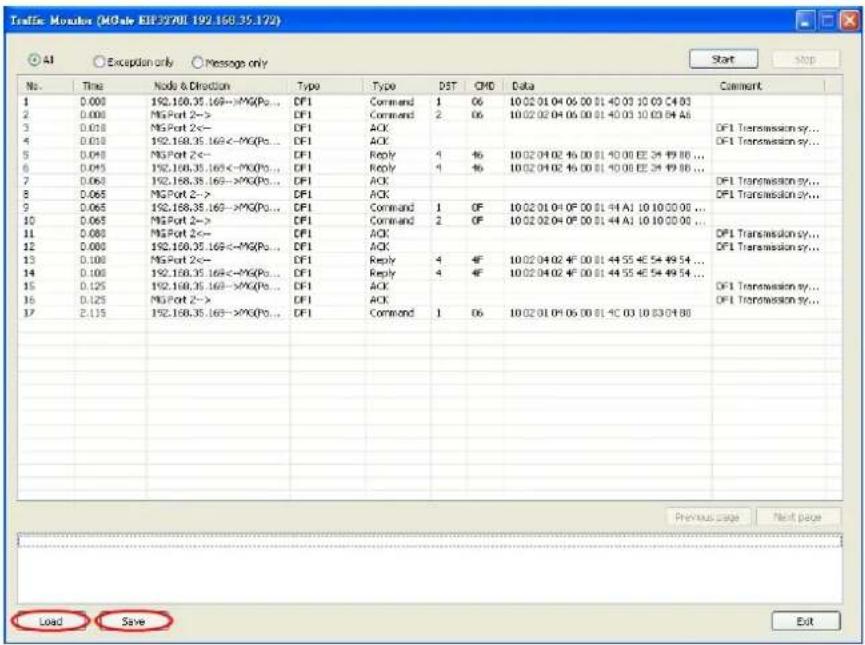
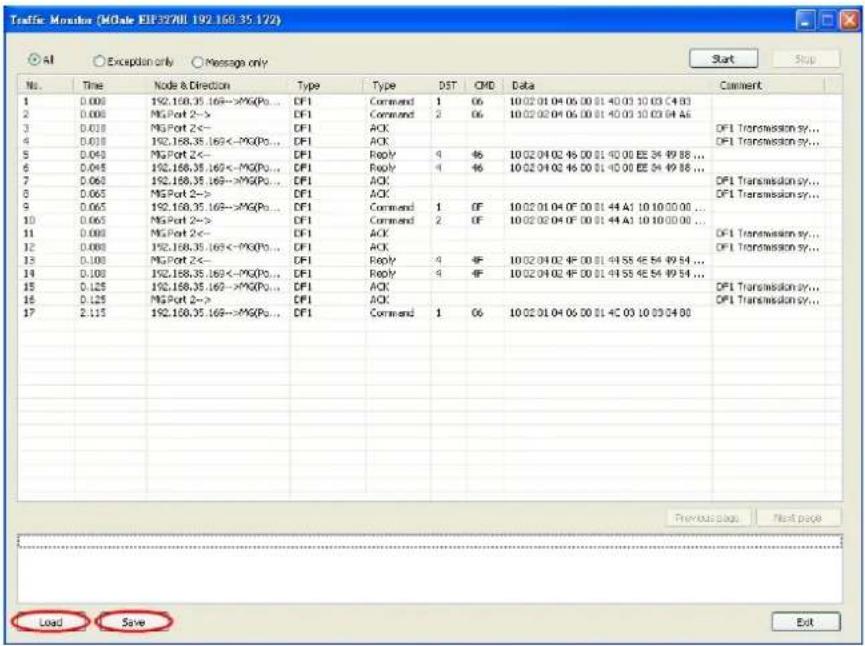
By default, all events are displayed in the traffic monitor window. MGate Manager also allows the data to be filtered so only the relevant information is displayed. The filter is selected using the radio buttons and customized using the "Filter info" field, as follows:
| Filter Description |
| All Show all traffic |
| Exception only Show only exceptions |
| Message only Show only traffic of PCCC communication |
Save Log to File
To save the data log to a file, click Save. You may retrieve a saved log by clicking Load.
Upgrading Firmware
Firmware updates for the MGate EIP3000 are located at www.moxa.com. After you have downloaded the new firmware onto your PC, you can use MGate Manager to write it onto your MGate EIP3000. Select the desired unit from the list in MGate Manager and click Upgrade Firmware to begin the process.
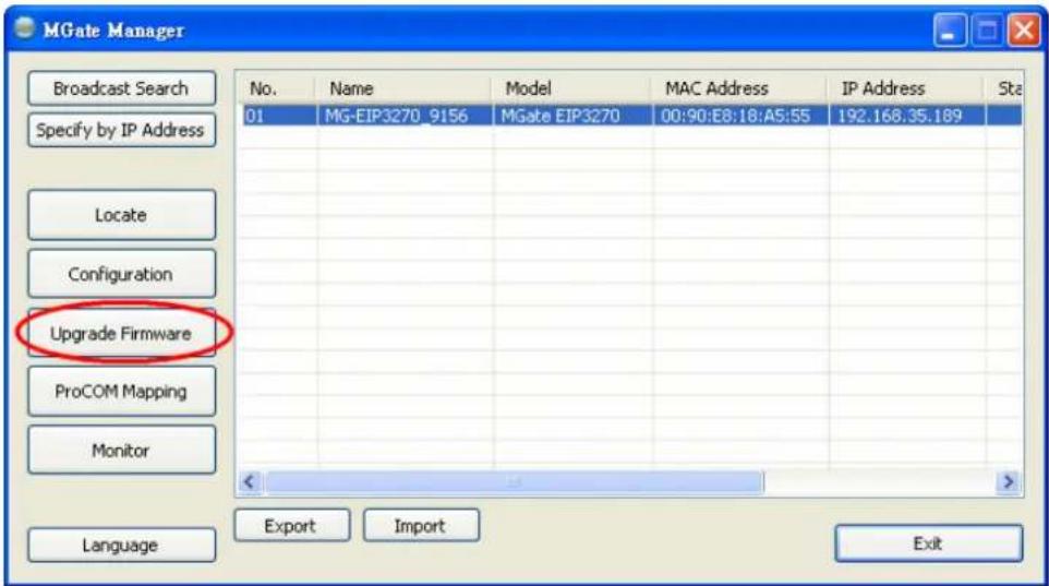
The dialog boxes will guide you through the process. You will need to browse your PC for the firmware file. Make sure that it matches your model.
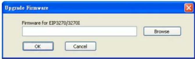
As the firmware is written to the unit, progress is displayed in the window.
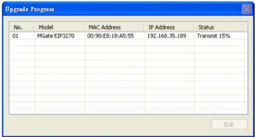
Once the firmware has been successfully written onto the unit, click Exit to close the Upgrade Firmware window. MGate Manager will automatically execute a Broadcast Search for all MGate EIP3000 units on the LAN. Your MGate should reappear in the list of units.
We discuss the following topics in this chapter:
□ DB9 (Male)
☐ Terminal Block (RS-422)
☐ Power Input, Relay Output
DB9 (Male)
The MGate EIP3000 uses DB9 (male) serial ports to connect DF1 devices. Each port supports two serial interfaces:
RS-232 and RS-422.
| Pin RS-232 RS-422 | ||
| 1 | DCD | TxD- |
| 2 | RxD | TxD+ |
| 3 | TxD | RxD+ |
| 4 | DTR | RxD- |
| 5 | GND | GND |
| 6 | DSR | --- |
| 7 | RTS | --- |
| 8 | CTS | --- |
EIP3170, EIP3170I
| Pin RS-232 | |
| 1 | DCD |
| 2 | RxD |
| 3 | TxD |
| 4 | DTR |
| 5 | GND |
| 6 | DSR |
| 7 | RTS |
| 8 | CTS |
Terminal Block (RS-422)
The EIP3170 and EIP3170I have a terminal block connector for RS-422 signal.
| Pin RS-422 | |
| 1 | TxD+ |
| 2 | TxD- |
| 3 | RxD+ |
| 4 | RxD- |
| 5 | GND |
Power Input, Relay Output
| V2+ | V2- | V1+ | V1- | |||
| Shielded Ground | DC Power Input 1 | DC Power Input 1 | Relay Output | Relay Output | DC Power Input 2 | DC Power Input 2 |