RTLTE-324-VZ - Router B&B Electronics - Free user manual and instructions
Find the device manual for free RTLTE-324-VZ B&B Electronics in PDF.

User questions about RTLTE-324-VZ B&B Electronics
0 question about this device. Answer the ones you know or ask your own.
Ask a new question about this device
Download the instructions for your Router in PDF format for free! Find your manual RTLTE-324-VZ - B&B Electronics and take your electronic device back in hand. On this page are published all the documents necessary for the use of your device. RTLTE-324-VZ by B&B Electronics.
USER MANUAL RTLTE-324-VZ B&B Electronics
Internaonal Headquarters
B&B Electronics Mfg. Co. Inc.
707 Dayton Road
Oawa, IL 61350 USA
Phone (815) 433-5100 -- General Fax (815) 433-5105
Website: www.bb-elec.com
support@bb-elec.com
European Headquarters
B&B Electronics
Westlink Commercial Park
Oranmore, Co. Galway, Ireland
Phone +353 91-792444 -- Fax +353 91-792445
Website: www.bb-europe.com
techsupport@bb-elec.com
© 2014 B&B Electronics
Document: SPECTRE_Conguraon_Manual_R4_1414m
CONTENTS
Table List 5
Figure List 6
Document Informaon 9
- ROUTER CONFIGURATION USING A WEB BROWSER 10
SECURED ACCESS TO WEB CONFIGURATION 11
GENERAL 11
Mobile Connecon 11
Primary LAN 12
WIFI 12
Peripheral Ports 12
System Informaon 12
MOBILE WAN STATUS 12
NETWORK STATUS 14
DHCP STATUS 16
IPSEC STATUS 17
DYNDNS STATUS 17
SYSTEM LOG 18
Connecon to mobile network conneccon 27
Sprint CDMA network conncon 29
DNS address conguraon 30
Check conncon to mobile network conguraon 30
Data limit conguraon 30
Switching between SIM cards or networks 30
PPPoE bridge mode conguraon 32
BACKUP ROUTES 33
PPPOE CONFIGURATION 34
LTE FIREWALL CONFIGURATION 35
3G and RT FIREWALL CONFIGURATION 37
NAT CONFIGURATION 39
OPENVPN TUNNEL CONFIGURATION 42
IPSEC TUNNEL CONFIGURATION 46
GRE TUNNELS CONFIGURATION 50
L2TP TUNNEL CONFIGURATION 52
PPTP TUNNEL CONFIGURATION 54
DYNDNS CLIENT CONFIGURATION 56
NTP CLIENT CONFIGURATION 56
SET SMS SERVICE CENTER ADDRESS 81
UNLOCK SIM CARD 81
SEND SMS 82
WI-FI ACCESS POINT 85
WLAN DHCP 86
WIRELESS NETWORK SCANNING 87
WI-FI START LOG
SYSTEM LOG
WI-FI ACCESS POINT CONFIGURATION
WLAN CONFIGURATION
WI-FI PORT LEDS
88
88
89
92
92
TABLE LIST
Table 1: Mobile Connecon .... 11
Table 2: Peripheral ports....12
Table 3: System informaon .... 12
Table 4: Cellular network informaon....13
Table 5: Descripon of period....13
Table 6: Mobile network stascs....13
Table 7: Trac stascs....14
Table 8: Interface conncon status....14
Table 9: Descripon of informaon in network status 15
Table 10: DHCP status descripon....16
Table 11: DynDNS report ...... 18
Table 12: Conguraon of network interface....19
Table 13: Conguraon of a dynamic DHCP server 20
Table 14: Conguraon of stac DHCP server 20
Table 15: VRRP conguration....24
Table 16: Check connection....24
Table 17: GPRS conneccon conguraon....27
Table 18: Check connection to mobile network conguraon....30
Table 19: Data limit conguraon....30
Table 20: Default and backup SIM conguraon....31
Table 21: Switch between SIM card conguraons....31
Table 22: Switch between SIM card conguraons....31
Table 23: Backup routes....33
Table 24: PPoE conguraon 34
Table 25: LTE Firewall configuraon 35
Table 26: LTE Firewall configuraon 36
Table 27: 3G and RT Firewall conguraon 38
Table 28: NAT conguraon 39
Table 29: Conguraon of send all incoming packets 39
Table 30: Remote access conguraon 40
Table 32: OpenVPN conguraon....43
Table 33: Example of OpenVPN conguraon....46
Table 34: Overview IPsec tunnels 47
Table 35: IPsec tunnel conguraon....47
Table 36: Example 8 - IPsec conguraon ....50
Table 37: Overview GRE tunnels....50
Table 38: GRE tunnel conguraon ....51
Table 39: Example 9 - GRE tunnel conguraon....52
Table 40: L2TP tunnel conguraon 52
Table 41: Example 10 - L2TP tunnel conguraon....53
Table 42: PPTP tunnel conguraon....54
Table 43: Example 11 - PPTP tunnel conguraon 55
Table 44: DynDNS conguraon 56
Table 45: NTP conguraon....56
Table 46: SNMP agent conguraon ....57
Table 47: SNMPv3 conguration....57
Table 48: SNMP conguraon (MBUS extension)....58
Table 49: SNMP conguraon (R-SeeNet) 58
Table 50: Object identifier for binary input and output....58
Table 51: Object identifier for CNT port....58
Table 52: Object identifier for M-BUS port 59
Table 53: SMTP client conguraon ....61
Table 54: Send SMS conguraon ....62
Table 55: Control via SMS conguraon....63
Table 56: SMS control commands....63
Table 57: Send SMS on serial PORT1 conguraon 63
Table 58: Send SMS on serial PORT2 conguraon 63
Table 59: Send SMS on Ethernet Port conguraon 64
Table 60: AT commands to send and receive SMS messages....64
Table 62: TCP Keep-Alive conguraon....71
Table 63: CD signal descripon....7
Table 64: DTR signal descripon ....71
Table 65: USB port conguraon 1....74
Table 66: USB port conguraon 2....74
Table 67: CD signal descripon....74
Table 68: DTR signal descripon 75
Table 69: Automac update conguraon....79
Table 71: Wi-Fi AP state 85
Table 72: Wi-Fi client state....85
Table 73: Lease address 86
Table 74: Neighboring Wi-Fi networks....87
Table 75: Wi-Fi AP parameters....89
Table 76: WLAN parameter....92
Table 77: Wi-Fi LED state indicaon....92
FIGURE LIST
Figure 1: Web Conguraon....10
Figure 2: Mobile WAN Status....14
Figure 3: Network Status....16
Figure 4: DHCP Status....17
Figure 5: IPsec Status ....17
Figure 6: DynDNS status....17
Figure 7: System log 18
Figure 8: Example syslogd startup script with the parameter -r....19
Figure 9: Example 1 - Network Topology for Dynamic DHCP Server 20
Figure 10: Example 1 - LAN Conguraon Page....21
Figure 11: Example 2 - Network Topology with both Stac and Dynamic DHCP Servers 22
Figure 12: Example 2 - LAN Conguraon Page....22
Figure 13: Example 3 - Network Topology ......23
Figure 14: Example 3 - LAN Conguraon Page....23
Figure 15: Example 4 - Network Topology for VRRP conguraon....25
Figure 16: Example 4 - VRRP conguraon of main router 25
Figure 17. Example 4 - VRRP congruration of backup router....25
Figure 18: Cellular WAN conguraon ....26
Figure 19: Advanced CDMA administraon 29
Figure 20: Example of Mobile WAN congruration 1....32
Figure 21: Example of Mobile WAN congruration 2....32
Figure 22: Example of Mobile WAN conguration 3....33
Figure 23: Backup Routes....34
Figure 24: PPPoE conguraon....35
Figure 25: LTE Firewall conguraon....36
Figure 26: Example 5 - Network Topology for Firewall Applicaon....37
Figure 27: Example 5 – LTE Firewall conguration....37
Figure 28: Example 5 - Network Topology for Firewall Applicaon....38
Figure 29: Example 5 – 3G and RT Firewall conguraon....39
Figure 30: Example 6 - Network Topology for basic NAT....40
Figure 31: Example 6 - Basic NAT conguraon ....41
Figure 32: Example 7 - Network topology for advanced NAT 41
Figure 33: Example 7 - Advanced NAT conguraon....42
Figure 34: OpenVPN tunnel conguraon 42
Figure 35: OpenVPN tunnel conguraon 45
Figure 36: Topology of example OpenVPN conguration....46
Figure 37: IPsec tunnels conguraon....47
Figure 38: IPsec tunnel conguraon 49
Figure 39: Example 8 - Network topology for IPsec tunneling....50
Figure 40: GRE tunnels configuraon ....51
Figure 41: GRE tunnel conguraon ....51
Figure 42: Network topology for GRE tunneling....52
Figure 43: L2TP tunnel conguraon....53
Figure 44: Example 10 - Network topology for L2TP tunneling ....53
Figure 45: PPTP tunnel conguraon....54
Figure 46: Example 11 - Network topology for PPTP tunneling conguraon ..... 55
Figure 47: Example of DynDNS conguraon ....56
Figure 48: Example of NTP conguraon....57
Figure 49. Example of SNMP conguraon 60
Figure 50. Example of the MIB browser....60
Figure 51. SMTP conguraon....61
Figure 52. Example of SMS conguraon 1 67
Figure 53. Example of SMS conguraon 2 68
Figure 54. Example of SMS conguraon 3 69
Figure 55. Example of SMS conguraon 4 70
Figure 56. Expansion port conguraon....72
Figure 57. example of Ethernet to serial communicaon....73
Figure 58. Example of serial port extension....73
Figure 59. USB conguration....75
Figure 60. Example of Ethernet to serial using USB port 76
Figure 61. Example of serial extension using USB port....76
Figure 62. Startup script....77
Figure 63. Example of startup script ....77
Figure 64. Up/Down script....78
Figure 65. Example of Up/Down script ...... 78
Figure 66. Example of automac update 1....79
Figure 67. Example of automac update 2....80
Figure 68. User modules 80
Figure 69. Change prole....80
Figure 70. Change password ....81
Figure 71. Set real me clock....81
Figure 72. Set SMS service center address....81
Figure 73. Unlock SIM card 82
Figure 74. Send SMS....82
Figure 75. Restore conguraon....83
Figure 76. Update rmware....83
Figure 77: Reboot....84
Figure 78: Wi-Fi AP status 86
Figure 79. Wi-Fi DHCP status....86
Figure 80. Wi-Fi Scan....87
Figure 81. Wi-Fi AP start log....88
Figure 82. System log 88
Figure 83. Wi-Fi AP conguraon page....91
Figure 84. WLAN conguraon 92
DOCUMENT INFORMATION
No part of this publicaon may be reproduced or transmied in any form or by any means, electronic or mechanical, including photography, recording, or any informaon storage and retrieval system without written consent. Informaon in this manual is subject to change without noce, and does not represent a commitment on the part of B&B Electronics Mfg. Co. Inc.
B&B Electronics Mfg. Co. Inc. shall not be liable for incidental or consequential damages resulting from the furnishing, performance, or use of this manual.
All brand names used in this manual are the registered trademarks of their respective owners. The use of trademarks or other designaons in this publicaon is for reference purposes only and does not constitute an endorsement by the trademark holder.
Used symbols

Danger – Informaon regarding user safety or potenal damage to the router.

Aenon - Problems that can arise in specific situations.

Useful ps or informaon of special interest.
GPL license
Source codes under GPL license are available free of charge by sending an email to support@bb-elec.com.
Router version
The properes and sengs associated with the cellular network conncon are not available in non-cellular SPECTRE RT routers.
PPPoE conguraon is only available on SPECTRE RT routers. It is used to set the PPPoE conncon over Ethernet.

Declared quality system ISO 9001

B&B Electronics
1. ROUTER CONFIGURATION USING A WEB BROWSER

Aenon! The SPECTRE cellular router will not operate unless the cellular carrier has been correctly congured and the account acvated and provisioned for data communicaons. For UMTS and LTE carriers, a SIM card must be inserted into the router. Do not insert the SIM card when the router is powered up.
You can monitor the status, conguraon and administraon of the router via the Web interface. To access the router over the web interface, enter hp://xxx.xxx.xxx.xxx into the URL for the browser where xxx.xxx.xxx.xxx is the router IP address. The modem's default IP address is 192.168.1.1. The default username is "root" and the default password is "root".
The le side of the web interface displays the menu. You will nd links for the Status, Conguraon and Administraon of the router.
Name and Location displays the router's name, locaon and SNMP conguraon (See SNMP conguraon). These elds are user-dened for each router.
For enhanced security, you should change the default password. If the router's default password is set, the menu item "Change password" is highlighted in red.
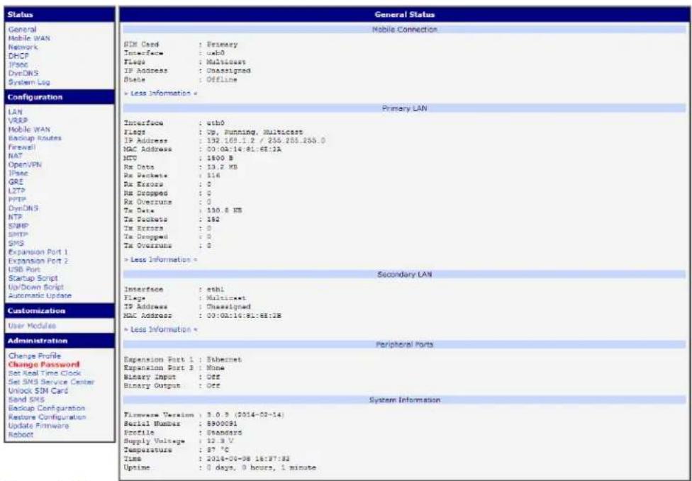
Figure 1: Web Conguraon
If the green LED is blinking, you may restore the router to its factory default sengs by pressing RST on front panel. The conguraon will be restored to the factory defaults and the router will reboot. (The green LED will be on during the reboot.)
SECURED ACCESS TO WEB CONFIGURATION
The Web interface can be accessed through a standard web browser via a secure HTTPS conncon.
Access the web interface by entering hps://192.168.1.1 in the web browser. You may receive a message that there is a problem with the website's security cercate. If you do, click on "Connue to this website". If you wish to prevent this message, you must install a security cercate into the router.
Since the domain name in the cercate is given the MAC address of the router (such addresses use dashes instead of colons as separators), it is necessary to access the router under this domain name. For access to the router via a domain name, a DNS record must be added to the DNS table in the operang system.
There are three methods to add a domain name to the operang system:
- Eding /etc/hosts (Linux/Unix)
- Eding C:\WINDOWS\system32\drivers\etc\hosts (Windows XP)
• Conguring your own DNS server
You must then add a security cercate to the web server on the router. When using a self-signed cercate, you must upload your les to the certs directory /etc/certs in the router.
GENERAL
A summary of basic informaon about the router and its advies can be invoked by selecng the General menu item. This page is also displayed when you login to the web interface. Informaon is divided into several of separate blocks according to the type of router acvity or the properes area – Mobile Connecon, Primary LAN, Peripherals Ports and System Informaon. If your router is equipped with a Wi-Fi expansion port, there is also a Wi-Fi secon.
MOBILE CONNECTION
Table 1: Mobile Connecon
| Item | Descripon |
| SIM Card | Idencaon of the SIM card (Primary or Secondary) |
| Interface | Denes the interface |
| Flags | Denes the ags (Example: Up, Running, Mulcast) |
| IP address | IP address of the interface |
| MTU | Maximum packet size that the equipment is able to transmit |
| Rx Data | Total number of received bytes |
| Rx Packets | Received packets |
| Rx Errors | Erroneous received packets |
| Rx Dropped | Dropped received packets |
| Rx Overruns | Lost received packets because of overload |
| Tx Data | Total number of sent bytes |
| Tx Packets | Sent packet |
| Tx Errors | Erroneous sent packets |
| Tx Dropped | Dropped sent packets |
| Tx Overruns | Lost sent packets because of overload |
| Upme | Time indicang how long the conncon to mobile network is established |
PRIMARY LAN
Items displayed in this part have the same meaning as items in the previous part. Moreover, there is information about the MAC address of the router (MAC Address item).
WIFI
Items displayed in this part have the same meaning as items in the previous part. (This is displayed if your model has a Wi-Fi.)
PERIPHERAL PORTS
Table 2: Peripheral ports
| Item | Descripon |
| Expansion Port 1 | Expansion port ed to the posion 1 (None indicates that this posion is equipped with no port) |
| Expansion Port 2 | Expansion port ed to the posion 2 (None indicates that this posion is equipped with no port) |
| Binary Input | State of binary input |
| Binary Output | State of binary output |
SYSTEM INFORMATION
Table 3: System informaon
| Item | Descripon |
| Firmware Version | Informaon about the rmware Version |
| Serial Number | Serial number of the router (in case of N/A is not available) |
| Prole | Current prole – standard or alternate proles (proles are used for example to switch between dierent modes of operaon) |
| Supply Voltage | Supply voltage of the router |
| Temperature | Temperature in the router |
| Time | Current date and me |
| Upme | Time indicang how long the router is used |
MOBILE WAN STATUS
The SPECTRE RT industrial router does not display the Mobile WAN status onpon.
The Mobile WAN menu item contains current informaon about connecons to the mobile network. The rst part of this page (Mobile Network Informaon) displays basic informaon about the mobile network in which the router is operated. There is also informaon about the module, which is mounted in the router.
Table 4: Cellular network informaon
| Item | Descripon |
| Registraon | State of the network registraon |
| Operator | Species the operator in whose network the router is operated |
| Technology | Transmission technology |
| PLMN | Code of operator |
| Cell | Cell to which the router is connected |
| LAC | Located Area Code – unique number assigned to each locaon area |
| Channel | Channel on which the router communicates |
| Signal Strength | Signal strength of the selected cell |
| Signal Quality | Signal quality of the selected cell:• EC/IO for UMTS and CDMA technologies (It is the rao of the signal received from the pilot channel – EC – to the overall level of the spectral density, i.e. the sum of the signals of other cells – IO.)• RSRQ for LTE technology (Dened as the ratio (N x RSRP) / RSSI) |
| Neighbors | Signal quality of neighboring hearing cells |
| Manufacturer | Module Manufacturer |
| Model | Type of module |
| Revision | Revision of module |
| IMEI | IMEI (Internaonal Mobile Equipment Identity) number of module |
| ESN | ESN (Electronic Serial Number) number of module (for CDMA routers) |
| MEID | MEID (Mobile Equipment Idener) number of module |
If a neighboring cell is highlighted in red, there is a risk that the router may repeatedly switch between the neighboring cell and the primary cell. This can act the performance of the router. To prevent this, re-orient the antenna or use a direconal antenna.
The next secon of this window displays historical informaon about the quality of the cellular WAN connec on during each logging period. The router has standard intervals, such as the previous 24 hours and last week, and also includes informaon one user-dened interval.
Table 5: Descripon of period
| Period | Descripon |
| Today | Today from 0:00 to 23:59 |
| Yesterday | Yesterday from 0:00 to 23:59 |
| This week | This week from Monday 0:00 to Sunday 23:59 |
| Last week | Last week from Monday 0:00 to Sunday 23:59 |
| This period | This accoung period |
| Last period | Last accoung period |
Table 6: Mobile network stascs
| Item | Descripon |
| Signal Min | Minimal signal strength |
| Signal Avg | Average signal strength |
| Signal Max | Maximal signal strength |
| Cells | Number of switch between cells |
| Availability | Availability of the router via the mobile network (expressed as a percent-age) |
Tips for Mobile Network Stascs table:
- Availability of conncon to mobile network informaon is expressed as a percentage that is calculated by the rao of the me when conncon to a mobile network is established to the me when the router is turned on.
- When you place your cursor on the maximum or minimum signal strength, you will be shown the last me the router reached this signal strength. The middle part of this page displays informaon about transferred data and number of connecons for both SIM card (for each period).
Table 7: Trac stascs
| Item | Descripon |
| RX data | Total volume of received data |
| TX data | Total volume of sent data |
| Connecons | Number of conneccon to mobile network establish |
The last part (Mobile Network Connecon Log) displays informaon about the mobile network conncon and any problems that occurred while establishing them.
| Mobile WAN Status | ||||||
| Mobile Network Information | ||||||
| Registration : Home Network Operator : T-Mobile CZ Technology : EDOE PLNN : 23001 Cell : 69A6 LAC : 353E Channel : 30 Signal Strength : -71 dBm Neighbours : -83 dBm (80), -81 dBm ($7), -93 dBm (59) » More Information « | ||||||
| Mobile Network Statistics | ||||||
| Today | Yesterday | This Week | Last Week | This Period | Last Period | |
| Signal Min : -108 dBm | -121 dBm | -121 dBm | -121 dBm | -121 dBm | -121 dBm | -121 dBm |
| Signal Avg : -71 dBm | -71 dBm | -71 dBm | -71 dBm | -69 dBm | -70 dBm | -85 dBm |
| Signal Max : -65 dBm | -65 dBm | -65 dBm | -65 dBm | -63 dBm | -63 dBm | -58 dBm |
| Cells : 15 | 261 | 525 | 206 | 730 | 962 | |
| Availability : 99.7% | 99.7% | 99.7% | 99.7% | 99.7% | 99.7% | 97.5% |
| Traffic Statistics for Primary SIM card | ||||||
| Today | Yesterday | This Week | Last Week | This Period | Last Period | |
| Rx Data : 12 KB | 21 KB | 19402 KB | 6366 KB | 25766 KB | 18060 KB | |
| Tx Data : 13 KB | 19 KB | 5167 KB | 3382 KB | 8548 KB | 3726 KB | |
| Connections : 2 | 7 | 20 | 36 | 56 | 49 | |
| Traffic Statistics for Secondary SIM card | ||||||
| Today | Yesterday | This Week | Last Week | This Period | Last Period | |
| Rx Data : 0 KB | 0 KB | 0 KB | 0 KB | 0 KB | 0 KB | 0 KB |
| Tx Data : 0 KB | 0 KB | 0 KB | 0 KB | 0 KB | 0 KB | 0 KB |
| Connections : 0 | 0 | 0 | 0 | 0 | 0 | |
| Mobile Network Connection Log | ||||||
Figure 2: Mobile WAN Status
NETWORK STATUS
Select the Network menu item to view the current system informaon for the router. The upper part of the window displays detailed informaon about the acve interfaces.
Table 8: Interface conncon status
| Interface | Descripon |
| eth0, eth1 | Network interfaces |
| usb0 | Mobile Network interface (acve conncon to GPRS/EDGE/CDMA/LTE) |
| tun0 | OpenVPN tunnel interface |
| ipsec0 | IPSec tunnel interface |
| gre1 | GRE tunnel interface |
| ppp0 | PPPoE interface (Industrial RT Router only) |
| lo | Local loopback interface |
The following detailed informaon will be shown for each acve conncon.
Table 9: Descripon of informaon in network status
| Item | Descripon |
| HWaddr | Hardware MAC (unique) address of primary network interface |
| inet | IP address of primary network interface |
| P-t-P | IP address second ends conncon |
| Bcast | Broadcast address |
| Mask | Network Subnet Mask |
| MTU | Maximum transmiable packet size |
| Metric | Number of routers that the packet must pass through |
| RX | packets – number of received packetserrors – number of errorsdropped – number of dropped packetsoverruns – incoming packets lost because of overloadframe – number of frame errors |
| TX | packets – number of transmied packetserrors – number of packet errorsdropped – number of dropped packetsoverruns – number of outgoing packets lost because of overloadcarrier - outgoing packet errors resulting from the physical layer |
| collisions | Number of collisions on physical layer |
| txqueuelen | Number of packets in the transmit queue |
| RX bytes | Total number of received bytes |
| TX bytes | Total number of transmied bytes |
| Network Status | ||||||
| Interfaces | ||||||
| csh0 | Link encap:Ethernet HWaddr 00:0A:14:81:63:0D inet addr:192.168.1.1 Bcast:192.168.1.255 Mask:255.255.255.0 UP BROADCAST RUNNING MULTICAST MTU:1500 Metric:1 RX packets:1718 errors:0 dropped:0 overruns:0 frame:0 TX packets:106 errors:0 dropped:0 overruns:0 carrier:0 collisions:0 txqueuelen:32 RX bytes:177132 (172.9 KB) TX bytes:82186 (80.2 KB) Interrupt:23 | |||||
| lo | Link encap:Local Loopback inet addr:127.0.0.1 Mask:255.0.0.0 UP LOOPBACK RUNNING MTU:16436 Metric:1 RX packets:0 errors:0 dropped:0 overruns:0 frame:0 TX packets:0 errors:0 dropped:0 overruns:0 carrier:0 collisions:0 txqueuelen:0 RX bytes:0 (0.0 B) TX bytes:0 (0.0 B) | |||||
| usb0 | Link encap:Ethernet HWaddr 00:A0:C6:00:00:00 inet addr:100.90.7.37 Bcast:100.255.255.255 Mask:255.255.255.255 UP BROADCAST RUNNING MULTICAST MTU:1500 Metric:1 RX packets:0 errors:0 dropped:0 overruns:0 frame:0 TX packets:0 errors:0 dropped:0 overruns:0 carrier:0 collisions:0 txqueuelen:1000 RX bytes:0 (0.0 B) TX bytes:0 (0.0 B) | |||||
| Route Table | ||||||
| Destination | Gateway | Genmask | Flags | Metric | Ref | Use Iface |
| 192.168.254.254 | 0.0.0.0 | 255.255.255.255 | UH | 0 | 0 | 0 usb0 |
| 192.168.1.0 | 0.0.0.0 | 255.255.255.0 | U | 0 | 0 | 0 etho |
| 0.0.0.0 | 192.168.254.254 | 0.0.0.0 | US | 0 | 0 | 0 usbO |
Figure 3: Network Status
DHCP STATUS
Informaon about the DHCP server can be accessed by selecng the DHCP status. The DHCP server provides automac conguraon of the client devices connected to the router. The DHCP server assigns each device an IP address, subnet mask, default gateway (IP address of router) and DNS server (IP address of router).
For each client in the list, the DHCP status window displays the following informaon.
Table 10: DHCP status descripon
| Item | Descripon |
| lease | Assigned IP address |
| starts | Time that the IP address was assigned |
| ends | Time that the IP address lease expires |
| hardware ethernet | Hardware MAC (unique) address |
| uid | Unique ID |
| client-hostname | Computer name |
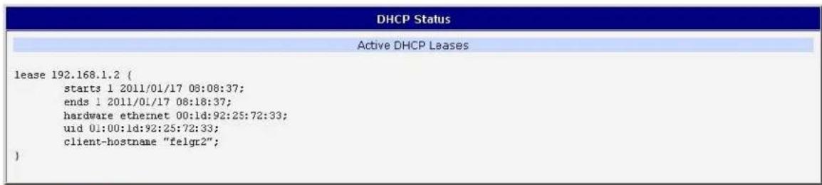
Figure 4: DHCP Status
The DHCP status may occasionally display two records for one IP address. This may be caused by reseng the client network interface.
IPSEC STATUS
Selecng the IPsec opon in the status menu of the web page will bring up the informaon for any IPsec Tunnels that have been established. Up to 4 IPsec tunnels can be created. If no IPsec tunnels are congured, the status will show that "IPsec is disabled".
If an IPsec tunnel is established, the router will show "IPsec SA established" (highlighted in red) in the IPsec status informaon.
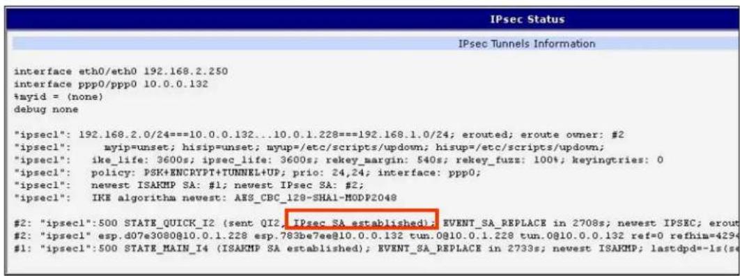
Figure 5: IPsec Status
DYNDNS STATUS
The router supports DynamicDNS using a DNS server on www.dyndns.org. If Dynamic DNS is congured, the status can be displayed by selecng menu opon DynDNS. Refer to www.dyndns.org for more informaon on how to congure a Dynamic DNS client.

Figure 6: DynDNS status
Table 11: DynDNS report
| DynDNS client is disabled. |
| Invalid username or password. |
| Specied hostname doesn’t exist. |
| Invalid hostname format. |
| Hostname exists, but not under specied username. |
| No update performed yet. |
| DynDNS record is already up to date. |
| DynDNS record successfully updated. |
| DNS error encountered. |
| DynDNS server failure. |
For Dynamic DNS to funcon properly, the router's SIM card must have a public IP address assigned.
SYSTEM LOG
Use the System Log menu item to view the router system log. The system log contains helpful informaon about the operaon of the router. Only the most recent informaon is shown on the screen, but older log entries can be viewed by saving the system log to a le and opening it with a text editor. The Save buon allows you to save the system log to a le. The system log is cleared when the unit re-boots.
![System Log System Messages 1970-01-01 00:00:24 pppd[491]: rcvd [LCP DiscReq id=0x1 magic=0x46e2fe3] 1970-01-01 00:00:24 pppd[491]: rcvd [CHAP Challenge id=0x1 00000000000000000000000000000000, name = "UNT'S_CHAP_SPVR"] 1970-01-01 00:00:24 pppd[491]: sent [CHAP Response id=0x1 0497e9b259c5ef6788141219541b7b08, name = ""] 1970-01-01 00:00:24 pppd[491]: rcvd [LCP EchoRep id=0x0 magic=0x46e2fe9 60 8d 8c 57] 1970-01-01 00:00:24 pppd[491]: rcvd [CHAP Success id=0x1 ""] 1970-01-01 00:00:24 pppd[491]: CHAP authentication succeeded 1970-01-01 00:00:24 last acoooge repeated 1 time 1970-01-01 00:00:24 pppd[491]: sent [IPCP ConfReq id=0x1 addr 0.8.0.0 ms-dns1 0.0.0.0 ms-dns3 0.0.0.0] 1970-01-01 00:00:24 pppd[491]: rcvd [IPCP ConfReq id=0x0] 1970-01-01 00:00:24 pppd[491]: sent [IPCP ConfNak id=0x0 addr 192.166.254.254] 1970-01-01 00:00:24 pppd[491]: rcvd [IPCP ConfNak id=0x1 addr 10.169.109.133 ms-dns1 93.153.117.1 ms-dns3 62.141.0.2] 1970-01-01 00:00:24 pppd[491]: sent [IPCP ConfReq id=0x2 addr 10.169.109.133 ms-dns1 93.153.117.1 ms-dns3 62.141.0.2] 1970-01-01 00:00:24 pppd[491]: rcvd [IPCP ConfReq id=Uxl] 1970-01-01 00:00:24 pppd[491]: sent [IPCP ConfACK id=Uxl] 1970-01-01 00:00:24 pppd[491]: rcvd [IPCP ConfACK id=Uxl addr 10.169.109.133 ms-dns1 93.153.117.1 ms-dns3 62.141.0.2] 1970-01-01 00:00:24 dncmasq[399]: reading /etc/resolv.conf 1970-01-01 00:00:24 dncmasq[399]: using nacserver 62.141.0.2#53 1970-01-01 00:00:24 dncmasq[399]: using nacserver 93.153.117.1#53 1970-01-01 00:00:24 pppd[491]: local IP address 192.166.254.254 1970-01-01 00:00:24 pppd[491]: remote IP address 93.153.117.1 1970-01-01 0C:src IP address 62.141. 62 197O-OTI-OTI-OTI-OTI-OTI-OTI-OTI-OTI-OTI-OTI-OTI-OTI-OTI-OTI-OTI-OTI-OTI- Pppd[49] : secondary DNS address 62.141. 62 Pppd[49] : Script /etc/scripts/ip-up started (pid 495) Pppd[49] : Script /etc/scripts/ip-up finished (pid 495), status = 3x Pppd[49] : root login on 'ttypo' Save](/content/2026/06/1187196/images/c4f1868f398645d5f99f7aa860bdc21b8eed94c32657647bc579347a3190fb19.jpg)
Figure 7: System log
The Syslog default size is 1000 lines. When the system log reaches the maximum size, it is deleted and a new log le is started.
The program syslogd can be run on the router to conjure the system log. The syslogd opon "-s" followed by a decimal number will set the maximum number of lines in the log le. The "-r" opon followed by the hostname or IP address will enable logging to a syslog daemon on a remote computer. On remote Linux machines, the syslog daemon is enabled by running syslogd with the parameter "-r". On remote Windows machines, a syslog server such as Syslog Watcher must be installed.
To enable remote logging when the router powers up, modify the script "/etc/init.d/syslog" or insert the commands "killall syslogd" and "syslogd

The following example shows how to send syslog informaon to a remote server at 192.168.2.115 on startup.
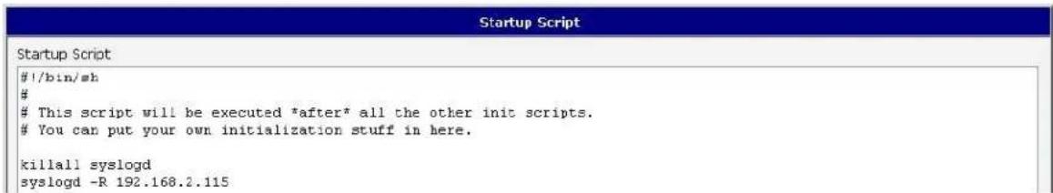
Figure 8: Example syslogd startup script with the parameter -r
LAN CONFIGURATION
Select the LAN menu item to enter the network conguraon for the Ethernet ports. The main Ethernet port, ETH, is setup in the Primary LAN section. If the router has additional Ethernet ports (PORT1 or PORT2), they are congured under the Secondary LAN secon. For routers with 2 additional Ethernet ports, PORT1 and PORT2 are automatically bridged together.
Table 12: Conguraon of network interface
| Item | Descripon |
| DHCP Client | disabled – The router will not obtain an IP address automacally from a DHCP server on the network.enabled – The router will aempt to obtain an IP address automacally from a DHCP server on the network. |
| IP address | Fixed IP address of the network interface. |
| Subnet Mask | IP address Subnet Mask for the interface. |
| Media type | Auto-negotiaon – The router automacally selects the communicaon speed of the network interface.100 Mbps Full Duplex – The router communicates at 100Mbps, in full-duplex mode.100 Mbps Half Duplex - The router communicates at 100Mbps, in half-duplex mode.10 Mbps Full Duplex - The router communicates at 10Mbps, in full-duplex mode.10 Mbps Half Duplex - The router communicates at 10Mbps, in half-duplex mode. |
| Default Gateway | IP address of Default gateway for the router. When entering IP address of default gateway, all packets for which the record was not found in the round table are sent to this address. |
| DNS server | IP address of the primary DNS server for the router. |
The DHCP server assigns the IP address, default gateway IP address, and IP address of the DNS server to the connected DHCP clients.
The DHCP server supports both stac and dynamic assignment of IP addresses. In Dynamic IP address assignment, the DHCP server will assign a client the next available IP address from the allowed IP address pool. Once the lease me on an IP address has expired, the DHCP server is free to re-assign that IP to another client.
Table 13: Conguraon of a dynamic DHCP server
| Item | Descripon |
| Enable dynamic DHCP leases | Select this opon to enable a dynamic DHCP server. |
| IP Pool Start | Starng IP address of the range allocated to the DHCP clients. |
| IP Pool End | Ending IP address of the range allocated to the DHCP clients. |
| Lease me | Time in seconds that the IP address is reserved before it can be re-used. |
The DHCP server can also assign a Stac IP address to a client. The MAC address of the client must be congured in the MAC address table along with the desired IP address. Up to 6 stac IP addresses are supported. Do not overlap the stac IP addresses with the addresses allocated by the dynamic DHCP address pool. Otherwise, the network may funcon incorrectly.
Table 14: Conguraon of stac DHCP server
| Item | Descripon |
| Enable stac DHCP leases | Select this opon to enable a stac DHCP server. |
| MAC Address | MAC address of a DHCP client. |
| IP Address | Assigned IP address. |
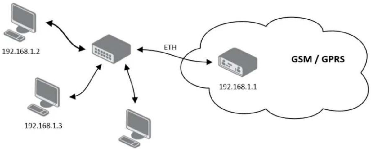
Example of the network interface conguraon for a dynamic DHCP server:
• The range of dynamically allocated addresses is from 192.168.1.2 to 192.168.1.4.
• The addresses are allocated for 600 seconds (10 minutes).
flowchart
graph TD
    A["192.168.1.2"] --> C["Central Server"]
    B["192.168.1.3"] --> C
    D["192.168.1.1"] --> C
    C --> E["GSM / GPRS"]
    style C fill:#ccc,stroke:#333
    note right of C ETH
192.168.1.4
Figure 9: Example 1 - Network Topology for Dynamic DHCP Server
| LAN Configuration | ||
| DHCP Client | Primary LAN disabled | Secondary LAN disabled |
| IP Address | 192.168.1.1 | |
| Subnet Mask | 255.255.255.0 | |
| Bridged | no no | |
| Media Type | auto-negotiation auto-negotiation | |
| Default Gateway | ||
| DNS Server | ||
| Enable dynamic DHCP leases | ||
| IP Pool Start | 192.168.1.2 | |
| IP Pool End | 192.168.1.4 | |
| Lease Time | 600 sec | |
| Enable static DHCP leases | ||
| MAC Address IP Address | ||
| Apply | ||
Figure 10: Example 1 - LAN Conguraon Page
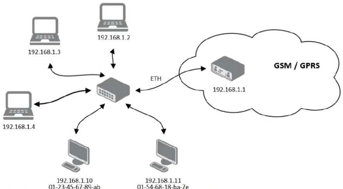
Example of the network interface conguraon with both dynamic and stac DHCP servers:
• The allocated address range is from 192.168.1.2 to 192.168.1.4.
• The address is allocated for 10 minutes.
• The client with MAC address 01:23:45:67:89:ab has IP address 192.168.1.10.
• The client with MAC address 01:54:68:18:ba:7e has IP address 192.168.1.11.
flowchart
graph TD
    A["192.168.1.3"] --> C["Central Server"]
    B["192.168.1.2"] --> C
    D["192.168.1.4"] --> C
    E["192.168.1.10 01-23-45-67-89-ab"] --> C
    F["192.168.1.11 01-54-68-18-ba-7e"] --> C
    C --> G["GSM / GPRS"]
    C --> H["ETH"]
    H --> I["192.168.1.1"]
Figure 11: Example 2 - Network Topology with both Stac and Dynamic DHCP Servers
| LAN Configuration | ||
| Primary LAN | Secondary LAN | |
| DHCP Client | disabled | disabled |
| IP Address | 192.168.1.1 | |
| Subnet Mask | 255.255.255.0 | |
| Bridged | no | no |
| Media Type | auto-negotiation | auto-negotiation |
| Default Gateway | ||
| DNS Server | ||
| Enable dynamic DHCP leases | ||
| IP Pool Start | 192.168.1.2 | |
| IP Pool End | 192.168.1.4 | |
| Lease Time | 600 | sec |
| Enable static DHCP leases | ||
| MAC Address | IP Address | |
| 01:23:45:67:89:ab | 192.168.1.10 | |
| 01:54:68:18:ba:7e | 192.168.1.11 | |
| Apply | ||
Figure 12: Example 2 - LAN Conguraon Page
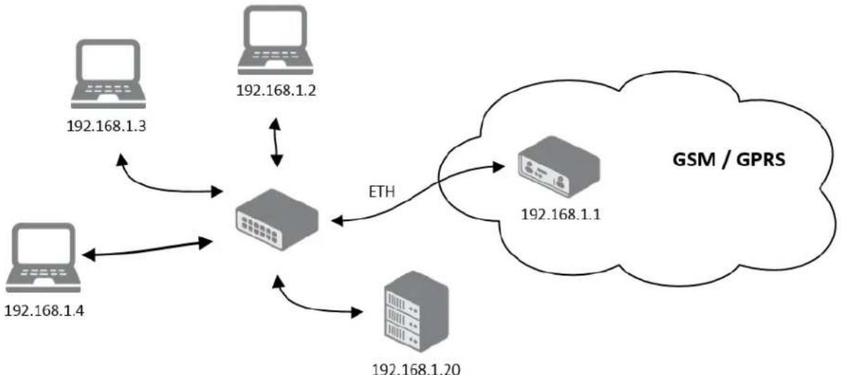
Example of the network interface conguraon with default gateway and DNS server:
- Default gateway IP address is 192.168.1.20
• DNS server IP address is 192.168.1.20
flowchart
graph TD
    A["192.168.1.3"] --> C["Switch"]
    B["192.168.1.2"] --> C
    D["192.168.1.4"] --> C
    E["192.168.1.20"] --> C
    C --> F["GSM / GPRS"]
    C -->|ETH| E
Figure 13: Example 3 - Network Topology
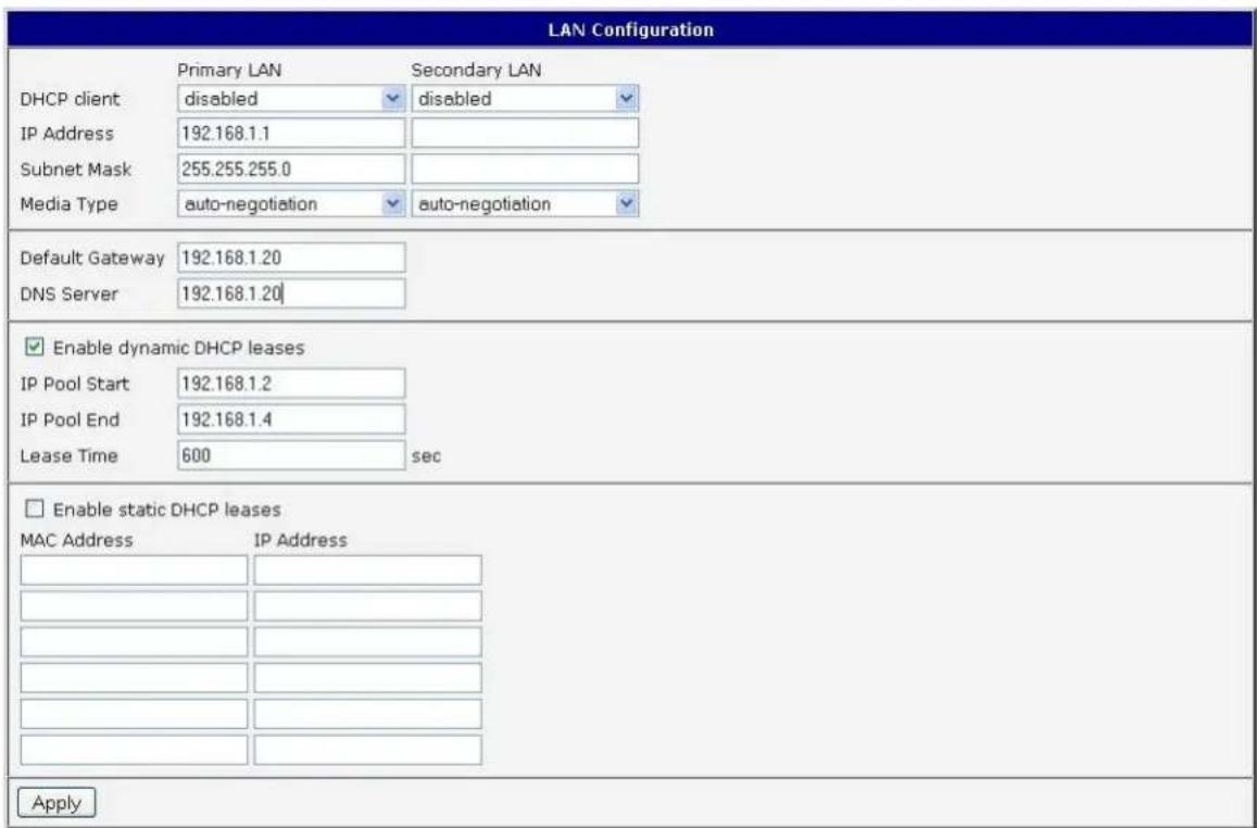
Figure 14: Example 3 - LAN Conguraon Page
VRRP CONFIGURATION
Select the VRRP menu item to enter the VRRP conguraon. VRRP protocol (Virtual Router Redundancy Protocol) allows you to transfer packet round from the main router to a backup router in case the main router fails. This can be used to provide a wireless cellular backup to a primary wired router in critical applications. If the Enable VRRP is checked, you may set the following parameters.
Table 15: VRRP conguraon
| Item | Descripon |
| Virtual Server IP Address | This parameter sets the virtual server IP address. This address must be the same for both the primary and backup routers. Devices on the LAN will use this address as their default gateway IP address. |
| Virtual Server ID | This parameter disnguishes one virtual router on the network from another. The main and backup routers must use the same value for this parameter. |
| Host Priority | The acve router with highest priority set by the parameter Host Priority, is the main router. According to RFC 2338, the main router should have the highest possible priority - 255. The backup router(s) have a priority in the range 1 – 254 (default value is 100). A priority value of 0 is not allowed. |
You may set the Check conncon ag in the second part of the window to enable automat test messages for the cellular network. In some cases, the mobile WAN conncon could sll be acve but the router will not be able to send data over the cellular network. This feature is used to verify that data can be sent over the PPP conncon and supplements the normal VRRP message handling. The currently acve router (main/backup) will send test messages to the dened Ping IP Address at periodic me intervals (Ping Interval) and wait for a reply (Ping Timeout). If the router does not receive a response to the Ping command, it will retry up to the number of mes specied by the Ping Probes parameter. Aer that me, it will switch itself to a backup router unl the PPP conncon is restored.
Table 16: Check conncon
| Item | Descripon |
| Ping IP Address | Desnaon IP address for the Ping commands. |
| Ping Interval | Interval in seconds between the outgoing Pings. |
| Ping Timeout | Time in seconds to wait for a response to the Ping. |
| Ping Probes | Maximum number of failed ping requests |
You may use the DNS server of the mobile carrier as the desnaon IP address for the test messages (Pings).
The Enable Trac Monitoring opon can be used to reduce the number of messages that are sent to test the PPP conncon. When this parameter is set, the router will monitor the interface for any packets dierent from a ping. If a response to the packet is received within the meout specied by the Ping Timeout parameter, then the router knows that the conncon is sll acve. If the router does not receive a response within the meout period, it will aempt to test the mobile WAN conncon using standard Ping commands.
Example of the VRRP protocol:
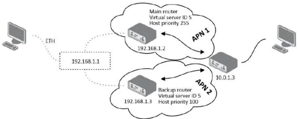
flowchart
graph TD
    A["Computer"] -->|ETH| B["192.168.1.1"]
    B --> C["Main router Virtual server ID 5 Host priority 255"]
    C --> D["APN 1"]
    D --> E["192.168.1.2"]
    E --> F["Backup router Virtual server ID 5 Host priority 100"]
    F --> G["APN 2"]
    G --> H["192.168.1.3"]
    H --> I["10.0.1.3"]
    I --> J["Computer"]
Figure 15: Example 4 - Network Topology for VRRP conguraon
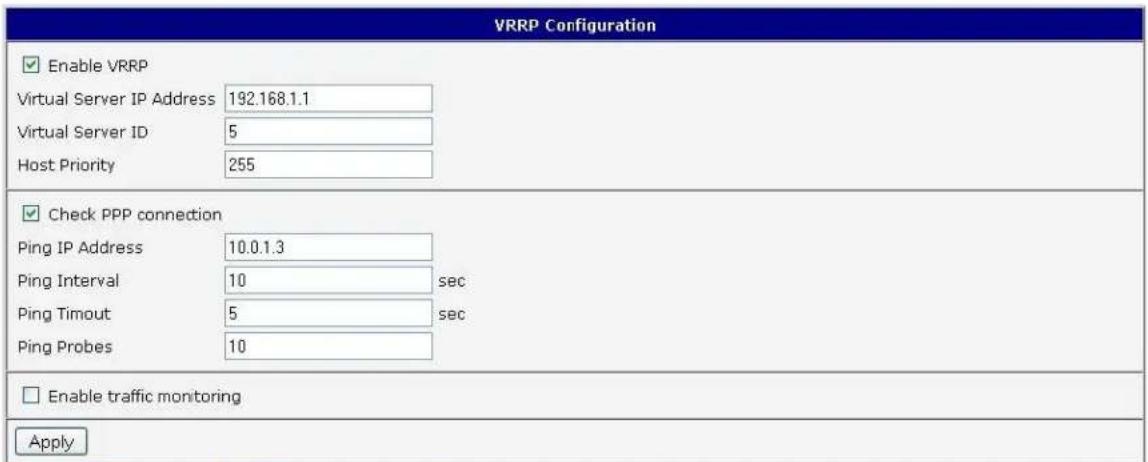
Figure 16: Example 4 - VRRP conguraon of main router
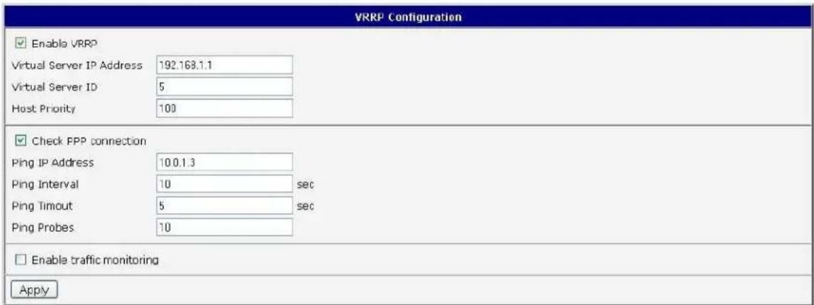
Figure 17. Example 4 - VRRP conguraon of backup router

The SPECTRE RT industrial router does not display the Mobile WAN Conguraon opon.
Select the Mobile WAN menu item to enter the cellular network conguraon page.
| Mobile WAN Configuration | ||
| ✓ Create connection to mobile network | ||
| Primary SIM card | Secondary SIM card | |
| Carrier | Generic UMTS | Generic UMTS |
| APN * | ||
| Username * | ||
| Password * | ||
| Authentication | PAP or CHAP | PAP or CHAP |
| IP Address * | ||
| Phone Number * | ||
| Operator * | ||
| Network Type | automatic selection | automatic selection |
| PIN * | ||
| MRU | 1500 | 1500 bytes |
| MTU | 1500 | 1500 bytes |
| DNS Settings | get from operator | get from operator |
| DNS Server | ||
| (The feature of check connection to mobile network is necessary for uninterrupted operation) | ||
| Check Connection | disabled | disabled |
| Ping IP Address | ||
| Ping Interval | ||
| □ Enable traffic monitoring | ||
| Data Limit | MB % | |
| Warning Threshold | ||
| Accounting Start | 1 | |
| Default SIM card | primary | |
| Backup SIM card | secondary | |
| □ Switch to other SIM card when connection fails □ Switch to backup SIM card when roaming is detected and switch to default SIM card when home network is detected □ Switch to backup SIM card when data limit is exceeded and switch to default SIM card when data limit isn't exceeded □ Switch to backup SIM card when binary input is active and switch to default SIM card when binary input isn't active □ Switch to default SIM card after timeout | ||
| Initial Timeout | 60 min | |
| Subsequent Timeout * | min | |
| Additive Constant * | min | |
| □ Enable PPPoE bridge mode * can be blank | ||
| Apply | ||
Figure 18: Cellular WAN conguraon
CELLULAR CARRIER SEL ECTION
The SPECTRE 3G Cellular Router can be congured to communicate on up to 2 UMTS or CDMA cellular networks. This allows the router to switch to a second carrier network if there is a problem with the primary network. The router can only communicate on one cellular network at a me and if redundancy is not required, then only one account needs to be acvated. For GSM/UMTS networks, the account informaon will be on the SIM card provided by the carrier. For CDMA networks, the account is provisioned over-the-air by the network provider and a SIM card is not required. The Mobile Equipment Idener (MEID) of the router must be provided to the CDMA network cellular carrier when the account is set up.
The primary and secondary cellular carriers are selected using the drop-down lists on the Cellular WAN conguraon page under the Primary and Secondary SIM card headings. The 3G router supports AT&T, Verizon, Sprint, T-Mobile, and Rogers Cellular networks. Verizon and Sprint have CDMA networks and the others are GSM networks. The default carrier is set to a generic UMTS provider. Refer to Sprint CDMA network conneccon secon below for acvang the router on the Sprint CDMA network.

The carrier selecon drop-down list is not available on LTE devices. For LTE devices, the carrier must be specied when ordering the router and the account sengs will be on the SIM card provided by the network operator.
CONNECTION TO MOBILE NETWORK CONNECTION
If the Create conncon to mobile network opon is selected, the router will automatically try to establish a conncon aer power up. If the aempt is unsuccessful, the router will re-boot and try again. For GSM/UMTS and LTE networks, the following network informaon can be congured. In most cases, the necessary informaon will be included on the SIM card provided by the carrier and these elds can be le empty or at their default values. Please contact your cellular network provider for more informaon.
Table 17: GPRS conncon conguraon
| Item | Descripon |
| Carrier | Generic, AT&T, T-Mobile, Sprint, Verizon (These are commonly used opons on the drop-down list only available on the 3G Models) |
| APN | Network idener (Access Point Name) |
| Username | User name to log into the GSM network |
| Password | Password to log into the GSM network |
| Authencaon | Authencaon protocol in GSM networkPAP or CHAP – Router is chose either authencaon method.PAP – Router will use PAP authencaon.CHAP – Router will use CHAP authencaon. |
| IP Address | IP address of SIM card. (Required if a stac IP address was assigned by the cellular carrier.) |
| Phone Number | Telephone number to dial a GPRS or CSD conncon. Router uses *99***1 # as the default telephone number. |
| Operator | PLNM code for the network operator |
| Network type | Automac selecon – The router will automacally select the network typeDepending upon the type of router, it is also possible to select a specic method of data transmission (GPRS, EDGE, UMTS ...). |
| PIN | PIN code for the SIM card. (Only required if the SIM card has been locked with a PIN to prevent unauthorized access) |
| MRU | (Maximum Receiving Unit) – The maximum packet size that can be received in a given environment. Default value is 1500 bytes. Other sengs may cause incorrect transmission of data. |
| MTU | (Maximum Transmission Unit) – The maximum packet size that can be transmied in a given environment. Default value is 1500 bytes. Other sengs may cause incorrect transmission of data. |
If the IP address eld is not lled in, the network operator will automatically assign an IP address when the conncon is established. If a stac IP address is supplied by the operator, the me required to connect to the network will be reduced.
If the APN eld is not lled in, the router will automatically select the APN based on the IMSI code of the SIM card. If the PLMN of the cellular carrier is not in the APN list, then default APN is "internet". Contact your mobile operator to determine if the APN informaon must be entered.

Access to the SIM card may be blocked if the PIN code for a locked SIM is entered incorrectly. Contact technical support if your SIM card becomes blocked.

If only one SIM card is installed in the router, the router switches between the APNs on the SIM card. A router with two SIM cards switches between SIM cards.

The items marked with an '*' should only be entered if they are required by the cellular network operator. If the router is unable to establish a Mobile Network conneccon, verify that the network sengs have been entered correctly. You may also try a dierent authencaon method or network type.
SPRINT CDMA NETWORK CONNECTION
The SPECTRE 3G router must be manually acvated on the Sprint network using the web interface aer the account has been set up by Sprint.
To acvate the router on the Sprint network:
- Ensure that a data account has been set up by Sprint. You will need to provide the MEID of the router to the Sprint account rep. This number can be found on the label on the boom of the router and on the outside of the router package. It can also be found on the Mobile WAN status web page when Sprint is selected as the primary carrier.
- Connect the antennas and Ethernet cable to the router and power up the device.
- Select Sprint as the primary carrier on the Mobile WAN conguraon web page. This will enable the CDMA Administraon menu item.
- Bring up the Advanced CDMA Administraon web page by clicking on the CDMA menu item under Administraon.
- Click on the Acvate Device buon to perform the over-the-air device acvaon. When it is complete, you can view the Mobile Device Number (MDN) on the Mobile WAN status page.
- If the acvaon fails, verify that the antenna connecons are ght and that the correct MEID has been set up on the Sprint network.
SPECTRE 3G UMTS/CDMA Router
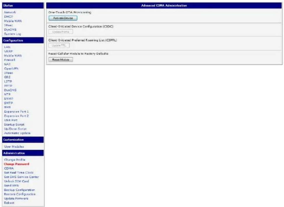
Figure 19: Advanced CDMA administraon
DNS ADDRESS CONFIGURATION
If Get DNS address from operator opon is selected, the router will automatically aempt to get the IP addresses for the primary and secondary DNS servers from the cellular network operator.
CHECK CONNECTION TO MOBILE NETWORK CONFIGURATION
You may set the Check conncon ag to enable automac test messages for the cellular network. In some cases, the PPP conncon may sll be acve but the router will not be able to send data over the cellular network. The router will send a Ping command to the Ping IP Address at periodic me intervals (Ping Interval) If the router does not receive a response to the Ping command, it will retry up to the number of mes specied by the Ping Probes parameter. Aer that me, it will switch itself to a backup router unl the mobile network conncon is restored.
Table 18: Check conncon to mobile network conguraon
| Item | Descripon |
| Ping IP Address | Desnaon IP address or domain name for the ping queries. |
| Ping Interval | Time intervals between the outgoing pings. |
If the Enable Trac Monitoring opon is selected, the router stops sending ping quesons to the Ping IP Address and it will watch trac in mobile network conncon. If mobile network conncon is without trac longer than the Ping Interval, then the router sends ping quesons to the Ping IP Address.
Note: It is recommended that you enable Check Connecon to ensure reliable data communicaon.
DATA LIMIT CONFIGURATION
The router can be congured to automacally send an SMS message or switch to a backup SIM card if the amount of data sent or received exceeds a given threshold for the monthly billing period.
Table 19: Data limit conguraon
| Item | Descripon |
| Data limit | With this parameter, you can set the maximum expected amount of data transmied (sent and received) over the cellular network in one billing period (month). |
| Warning Threshold | Percentage of Data Limit (50% to 99%). The router will send an SMS message with Router has exceeded (value of Warning Threshold) of data limit in the message text when this threshold is exceeded. |
| Accounting Start | Sets the day of the month in which the billing cycle starts for the SIM card being used. The start of the billing period is determined by the network operator. |
If neither one of the opons Switch to backup SIM card when data limit is exceeded (see next) or Send SMS when data limit is exceeded (see SMS conguraon) is selected, the data limit will be ignored.
SWITCHING BETWEEN SIM CARDS OR NETWORKS
You may denote rules in the router for switching between two APNs on one SIM card or between two SIM cards or network providers. The router can automatically switch between the network setups when the acve PPP conncon is lost, the data limit is exceeded, or the binary input on the front panel goes acve.

Table 20: Default and backup SIM conguraon
| Item | Descripon |
| Default SIM card | This parameter sets the default APN or SIM card for the PPP conncon. If this parameter is set tonone, the router boots up in o-line mode and it will be necessary to initiate the PPP conncon by sending an SMS message to the router. |
| Backup SIM card | Denes the backup APN or SIM card. |
If parameter Backup SIM card is set to none, then the parameters Switch to other SIM card when conncon fails, Switch to backup SIM card when roaming is detected and Switch to backup SIM card when data limit is exceeded will switch the router to o-line mode
Table 21: Switch between SIM card conguraons
| Item | Descripon |
| Switch to other SIM card when conncon fails | If the PPP conncon fails, the router will switch to the secondary SIM card or secondary APN of the SIM card. The router will switch to the backup SIM card if the router is unable to establish a PPP conncon aer 3 aempts or the Check the PPP conncon onop is selected and the router detects that the PPP conncon has failed. |
| Switch to backup SIM card when roaming is detected | If roaming is detected, this opon forces the router to switch to the secondary SIM card or secondary APN of the SIM card. |
| Switch to backup SIM card when data limit is exceeded | This opon enables the router to switch to the secondary SIM card or secondary APN of the SIM card when the data limit of default APN is exceeded. |
| Switch to backup SIM card when binary input is acve | This parameter forces the router to switch to the secondary SIM card or secondary APN of the SIM card when binary input ‘bin0’ is acve. |
| Switch to primary SIM card aer meout | This parameter denies the method the router will use to try to switch back to the default SIM card or default APN. |
The following parameters denote the amount of me that must elapse before the router will aempt to go back to the default SIM card or APN.
Table 22: Switch between SIM card conguraons
| Item | Descripon |
| Inial meout | The rst aempt to switch back to the primary SIM card or APN shall be made aer the me dened in the parameter Inial Timeout. The range of this parameter is from 1 to 10000 minutes. |
| Subsequent Timeout | Aer an unsuccessful aempt to switch to the default SIM card, the router will make a second aempt aer the amount of me dened in the parameter Subsequent Timeout. The range is from 1 to 10000 minutes. |
| Addive constant | Any further aempts to switch back to the primary SIM card or APN shall be made aer a meout computed as the sum of the previous meout period and the me dened in the parameter Addive constants. The range is from 1 to 10000 minutes. |
Example: Opon Switch to primary SIM card aer meout is checked and the parameters are set as follows: Inial Timeout = 60 min. Subsequent Timeout = 30 min. Addive Constant = 20 min.
The rst aempt to switch back to the primary SIM card or APN shall be carried out aer 60 minutes. The second aempt will be made 30 minutes later. The third aempt will be made aer 50 minutes (30+20). The fourth aempt will be made aer 70 minutes (30+20+20).
PPPOE BRIDGE MODE CO NFIGURATION
If the Enable PPPoE bridge mode opon is selected, the router will acvate the PPPoE bridge protocol. PPPoE (point-to-point over ethernet) is a network protocol for encapsulang Point-to-Point Protocol (PPP) frames inside Ethernet frames. This feature allows a device connected to the ETH port of the router to create a PPP conncon with the cellular network.
The gure below describes the situation, when the connection to mobile network is controlled on the address 8.8.8.8 in the measure of 60 seconds for primary SIM card and on the address www.google.com in the measure of 80 seconds for secondary SIM card. In the case of trace on the router the control pins are not sent, but the trace is monitored.
Figure 20: Example of Mobile WAN conguraon 1
Figure 21 shows an example of how to congregate the router to automatically switch to the backup SIM card when it exceeds the data limit of 800 MB in the billing period. It will send out a warning SMS message when 400 MB of data have been transmied. In the example shown, the billing period begins on the 18th day of the month.
| Data Limit | 800 | MB |
| Warning Threshold | 50 | % |
| Accounting Start | 18 | |
| Default SIM card | primary ▼ | |
| Backup SIM card | secondary ▼ | |
| □ Switch to other SIM card when connection fails □ Switch to backup SIM card when roaming is detected and switch to default SIM card when home network is detected ✓ Switch to backup SIM card when data limit is exceeded and switch to default SIM card when data limit isn't exceeded □ Switch to backup SIM card when binary input is active and switch to default SIM card when binary input isn't active □ Switch to default SIM card after timeout | ||
| Initial Timeout | 60 | min |
| Subsequent Timeout * | min | |
| Additive Constant * | min | |
Figure 21: Example of Mobile WAN conguraon 2
Example: Conguring the router to switch to oine mode when it detects that it is roaming. The rst aempt to switch back to the default SIM card is made aer 60 minutes, the second aer 40 minutes, the third aer 50 minutes (40 +10)...
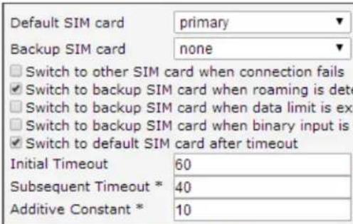
Figure 22: Example of Mobile WAN conguraon 3
BACKUP ROUTES
By using the conguraon form on the Backup Routes page, you can back up the primary conncon with alternate conncons to the Internet/mobile network. Each back up conncon can be assigned a priority. Switching between conncons is done based on set priories and the state of the conncons (for Primary LAN and Secondary LAN).
If the Enable backup routes switching opon is checked, the default route is selected according to the sengs below.
You can set the parameters for enabling each of backup route
If the Enable backup routes switching opon is not checked, the Backup routes system operates in the so-called backward compatibility mode. The default route is selected based on implicit priories according to the status of each enabled network interface. The names of backup routes and corresponding network interfaces, in order of implicit priories, are:
- Mobile WAN (pppX, usbX)
- PPPoE (ppp0)
• Secondary LAN (eth1)
• Primary LAN (eth0)
Example:
Secondary LAN is selected as the default route only if Create conncon to mobile network opon is not checked on the Mobile WAN page, alternatively if Create PPPoE conncon opon is not checked on the PPPoE page. To select the Primary LAN it is also necessary not to be entered IP address for Secondary LAN and must not be enabled DHCP Client for Secondary LAN.
Table 23: Backup routes
| Item | Descripon |
| Priority | Priority for the type of conncon |
| Ping IP Address | Desnaon IP address of ping queries to check the conncon (address cannot be specied as a domain name) |
| Ping Interval | Time intervals between sent ping queries |
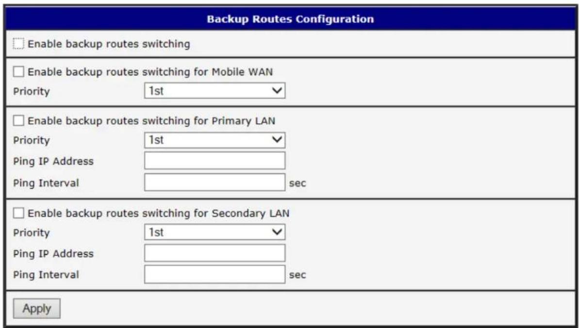
Figure 23: Backup Routes
PPPOE CONFIGURATION

The SPECTRE cellular router does not support the PPPoE conguraon opon. PPPoE conguraon is only available on SPECTRE RT routers. It is used to set the PPPoE conncon over Ethernet.
PPPoE (Point-to-Point over Ethernet) is a network protocol where PPP frames are encapsulated in Ethernet frames. The PPPoE feature in the SPECTRE RT industrial router operates in client mode. The router will connect to a PPPoE server or a PPPoE bridge device such as an ADSL modem.
To enter the PPPoE congruration, select the PPPoE menu item. If the Create PPPoE conncon on is selected, the router will aempt to establish a PPPoE conncon on power up. The PPPoE client will connect to devices that support either a PPPoE bridge or a PPPoE server. Aer a PPPoE conncon is established, the router obtains the IP address of the PPPoE Server device and all communications from the device are forwarded to the industrial router.
Table 24: PPoE conguraon
| Item | Descripon |
| Username | Username for secure access to PPPoE |
| Password | Password for secure access to PPPoE |
| Authencaon | Authencaon protocol in GSM networkPAP or CHAP – Router is chosen one of the authentication methods.PAP – It is used PAP authencaon method.CHAP – It is used CHAP authentication method. |
| MRU | (Maximum Receiving Unit) – The maximum packet size that can be received in the given environment. Default value is set to 1492 bytes. Other sengs may cause incorrect data transmission. |
| MTU | (Maximum Transmission Unit) – The maximum packet size that can be transmied in the given environment. Default value is set to 1492 bytes. Other sengs may cause incorrect data transmission |
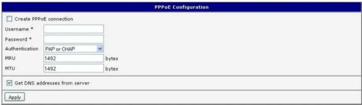
Figure 24: PPPoE conguraon
LTE FIREWALL CONFIGURATION
The rst security element which incoming packets must pass is check of enabled source IP address and desnaon ports. The IP address can be specied from which you can remotely access the router and the internal network connected behind a router. If the Enable Itering of incoming packets items is checked (located at the beginning of the conguraon form Firewall), this element is enabled and accessibility is checked against the table with IP addresses. This means that access is permied only to the address specied in the table. It is possible to dene up to eight remote accesses. There are the following parameters:
Table 25: LTE Firewall conguraon
| Item | Descripon |
| Source | IP address from which access to the router is allowed |
| Protocol | Species protocol for remote access• all – access is allowed by all• TCP – access is allowed by TCP• UDP – access is allowed by UDP• ICMP – access is allowed by ICMP |
| Target Port | The port number on which access to the router is allowed |
| Acon | Type of acon:• allow – access is allowed• deny – access is denied |

Cauon! The rewalls on the 3G and LTE models do not liter trac received over the Ethernet ports.
The following part of the conguraon form denies the forwarding policy. If enabled iterating of forwarded packets item is not checked, packets are automacally accepted. If this item is checked and incoming packet is addressed to another network interface, it will go to the FORWARD chain. In case that the FORWARD chain accepted this packet (there is a rule for its forwarding), it will be sent out. If the forwarding rule does not exist, packet will be dropped.
Then there is a table for dening the rules. It is possible to allow all trac within the selected protocol (rule species only protocol) or create stricter rules by speciying items for source IP address, desnaon IP address and port.
Table 266: LTE Firewall conguraon
| Item | Descripon |
| Source | IP address of source device |
| Desnaon | IP address of desnaon device |
| Protocol | Species protocol for remote accessall – access is allowed by allTCP – access is allowed by TCPUDP – access is allowed by UDPICMP – access is allowed by ICMP |
| Target Port | The port number on which access to the router is allowed |
| Acon | Type of acon:allow – access is alloweddeny – access is denied |
There is also the possibility to drop a packet whenever request for service which is not in the router comes (check box named Enable Itering of locally desnated packets). The packet is dropped automacally without any informaon.
As a protecon against DoS aacks (this means aacks during which the target system is ooded with plenty of meaningless requirements) is used on named Enable protected against DoS aacks which limits the number of connexons per second for ve.
| Firewall Configuration | |||
| Enable filtering of incoming packets Source * Protocol Target Port * Action | |||
| all ▼ | allow ▼ | ||
| all ▼ | allow ▼ | ||
| ICMP ▼ | allow ▼ | ||
| all ▼ | allow ▼ | ||
| all ▼ | allow ▼ | ||
| all ▼ | allow ▼ | ||
| all ▼ | allow ▼ | ||
| all ▼ | allow ▼ | ||
| all ▼ | allow ▼ | ||
| all ▼ | allow ▼ | ||
| Enabled filtering of forwarded packets Source * Destination * Protocol Target Port * Action | |||
| all ▼ | allow ▼ | ||
| all ▼ | allow ▼ | ||
| all ▼ | allow ▼ | ||
| all ▼ | allow ▼ | ||
| all ▼ | allow ▼ | ||
| all ▼ | allow ▼ | ||
| Enable filtering of locally destined packets | |||
| Enable protection against DoS attacks * can be blank | |||
| Apply | |||
Figure 25: LTE Firewall conguraon
Example rewall conguraon:
The router has allowed the following access:
• from host address 171.92.5.45 using any protocol
• from host address 10.0.2.123 using TCP protocol on any ports
• from host address 142.2.26.54 using ICMP protocol
flowchart
graph TD
    A["Computer 10.0.2.123"] --> B["Firewall"]
    C["Computer 171.92.5.45"] --> B
    D["Computer 142.2.26.54"] --> B
    B --> E["TCP/1000"]
    B --> F["ICMP"]
    B --> G["ALL"]
    E --> H["Server"]
    F --> I["Server"]
    G --> J["Server"]
Figure 266: Example 5 - Network Topology for Firewall Applicaon
Figure 277: Example 5 – LTE Firewall conguraon
3G and RT FIREWALL CONFIGURATION
The 3G and RT router rewall can be congured to only allow certain hosts to access the router and internal LAN network or it can only allow trac on a certain IP port to pass through to the internal network. Up to 8 Iters can be dened when the Allow remote access only from specied hosts opon is selected. The following parameters can be dened for each Iter: Source, Source IP Address, Protocol and Target Port.
Table 277: 3G and RT Firewall conguraon
| Item | Descripon |
| Source | IP address of source device |
| Desnaon | IP address of desnaon device |
| Protocol | Species protocol for remote accessall – access is allowed by allTCP – access is allowed by TCPUDP – access is allowed by UDPICMP – access is allowed by ICMP |
| Target Port | The port number on which access to the router is allowed |
| Acon | Type of acon:allow – access is alloweddeny – access is denied |

Cauon! The rewalls on the 3G and LTE models do not liter trac received over the Ethernet ports.
Example rewall conguraon:
The router has allowed the following access:
• from host address 171.92.5.45 using any protocol
• from host address 10.0.2.123 using TCP protocol on any ports
• from host address 142.2.26.54 using ICMP protocol
flowchart
graph TD
    A["Computer 10.0.2.123"] --> B["Firewall"]
    C["Computer 171.92.5.45"] --> B
    D["Computer 142.2.26.54"] --> B
    B -->|TCP/1000| E["TCP/1000"]
    B -->|ALL| F["ICMP"]
    B --> G["Server"]
    style B fill:#f9f,stroke:#333,stroke-width:2px
Figure 288: Example 5 - Network Topology for Firewall Applicaon
Figure 299: Example 5 – 3G and RT Firewall conguraon
NAT CONFIGURATION
NAT (Network address Translaon / Port address Translaon - PAT) is a method of sharing a single external IP address among many internal hosts. It also helps prevent unauthorized access to the internal network. To enter the Network Address Translaon configuraon, select the NAT menu item. Up to sixteen NAT rules may be dened.
Table 288: NAT conguraon
| Item | Descripon |
| Public Port | Public port |
| Private Port | Private port |
| Type | Protocol selecon |
| Server IP address | IP address which will be forwarded incoming data. |
If you need to set up more than 16 NAT rules, insert the following statement into the startup script
iptables -t nat -A napt -p tcp --dport [PORT_PUBLIC] -j DNAT --to-desnaon [IPADDR]:[PORT1_PRIVATE]
The IP address parameter [IPADDR] and port parameters [PORT_PUBLIC] and [PORT1_PRIVATE] must be lled in with the desired informaon.
The following opon can be used to route all incoming trac from the PPP to a single internal host address.
Table 299: Conguraon of send all incoming packets
| Item | Descripon |
| Send all incoming packets to default server | Select this item to route all trac received over the PPP conneccon to a single IP address on the internal network. |
| Default Server | Send all incoming packets to this IP address. |
You can also use common protocols to specify which ports to use for access to the router. In most cases, the default port for each protocol should not be changed.
Table 30: Remote access conguraon
| Item | Descripon |
| Enable remote HTTP access on port | Select this opon to allow access to the router using HTTP. |
| Enable remote HTTPS access on port | Select this opon to allow access to the router using HTTPS. |
| Enable remote FTP access on port | Select this opon to allow access to the router using FTP. |
| Enable remote SSH access on port | Select this opon to allow access to the router using SSH. |
| Enable remote Telnet access on port | Select this opon to allow access to the router using Telnet. |
| Enable remote SNMP access on port | Select this opon to allow access to the router using SNMP. |
| Masquerade outgoing packets | Select this opon to turn on NAT. |
Example NAT conguraon with one host connected to the router:
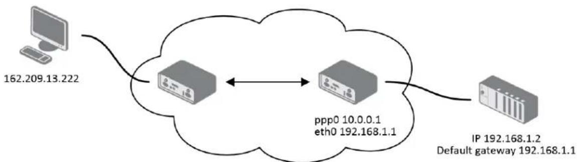
flowchart
graph LR
    A["Computer 162.209.13.222"] --> B((Cloud))
    B <--> C["ppp0 10.0.0.1 eth0 192.168.1.1"]
    C --> D["IP 192.168.1.2 Default gateway 192.168.1.1"]
Figure 300: Example 6 - Network Topology for basic NAT
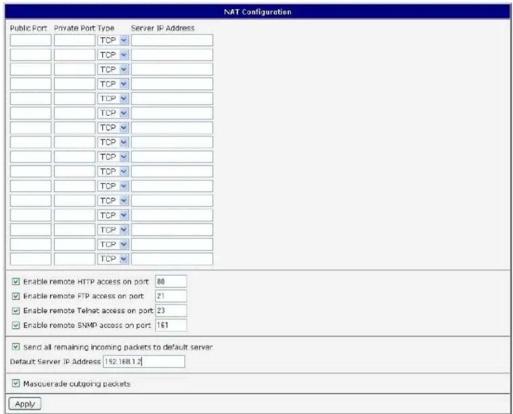
Figure 311: Example 6 - Basic NAT conguraon
In this conguraon, it is important to select Send all remaining incoming packets to default server.
Example NAT conguraon with additional connected equipment:
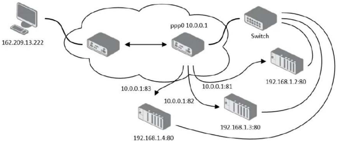
flowchart
graph TD
    A["162.209.13.222"] --> B(( )) --> C["ppp0 10.0.0.1"]
    B <--> C
    C --> D["Switch"]
    D --> E["192.168.1.2:80"]
    D --> F["192.168.1.3:80"]
    D --> G["192.168.1.4:80"]
    G --> H["10.0.0.1:83"]
    G --> I["10.0.0.1:82"]
    I --> J["10.0.0.1:81"]
    J --> K["192.168.1.4:80"]
Figure 322: Example 7 - Network topology for advanced NAT
| NAT Configuration | |||
| Public Port | Private Port Type | Server IP Address | |
| 81 | 80 | TCP ▼ 192.168.1.2 | |
| 82 | 80 | TCP ▼ 192.168.1.3 | |
| 83 | 80 | TCP ▼ 192.168.1.4 | |
| TCP ▼ | |||
| TCP ▼ | |||
| TCP ▼ | |||
| TCP ▼ | |||
| TCP ▼ | |||
| TCP ▼ | |||
| TCP ▼ | |||
| TCP ▼ | |||
| TCP ▼ | |||
| TCP ▼ | |||
| TCP ▼ | |||
| TCP ▼ | |||
| TCP ▼ | |||
| Enable remote HTTP access on port 80 Enable remote HTTPS access on port 443 Enable remote FTP access on port 21 Enable remote SSH access on port 22 Enable remote Telnet access on port 23 Enable remote SNMP access on port 161 | |||
| Send all remaining incoming packets to default server Default Server IP Address | |||
| Masquerade outgoing packets | |||
| Apply | |||
Figure 333: Example 7 - Advanced NAT conguraon
OPENVPN TUNNEL CONFIGURATION
Select the OpenVPN item to congregate an OpenVPN tunnel. OpenVPN is a protocol which is used to create a secure conncon between two LANs. Up to 2 OpenVPN tunnels may be created.
Table 31: Overview of OpenVPN tunnels
| Item | Descripon |
| Create | Enables the individual tunnels. |
| Descripon | Displays the name of the tunnel specied in the conguraon of the tunnel. |
| Edit | Select to congure an OpenVPN tunnel. |

Figure 344: OpenVPN tunnel conguraon
Table 312: OpenVPN conguraon
| Item | Descripon |
| Descripon | Descripon of tunnel. |
| Protocol | Protocol by which the tunnel will communicate.UDP – OpenVPN will communicate using UDP.TCP server – OpenVPN will communicate using TCP in server mode.TCP client – OpenVPN will communicate using TCP in client mode. |
| UDP/TCP port | Port by which the tunnel will communicate. |
| Remote IP Address | IP address of the opposite side of the tunnel. Can be used domain name. |
| Remote Subnet | Network IP address of the opposite side of the tunnel. |
| Remote Subnet Mask | Subnet mask of the opposite side of the tunnel. |
| Redirect Gateway | It is possible to redirect all trac on Ethernet. |
| Local Interface IP Address | IP address of the local side of tunnel. |
| Remote Interface IP Address | IP address of interface local side of tunnel. |
| Ping Interval | Parameter (in seconds) denes how oen the router will send a message to the remote end to verify that the tunnel is sll connected. |
| Ping Timeout | Parameter which denes how long the router will wait for a response to the ping (in seconds). Ping Timeout must be larger than Ping Interval. |
| Renegoate Interval | Parameter sets the renegoaon period (reauthorizaon) for the OpenVPN tunnel. Aer this me period, the router will re-establish the tunnel to ensure the connued security of the tunnel. |
| Max Fragment Size | Denes maximum packet size. |
| Compression | none – No compression is used.LZO – Lossless LZO compression. Compression has to be selected on both tunnel ends. |
| NAT Rules | not applied – NAT rules are not applied to OpenVPN tunnel.applied – NAT rules are not applied to OpenVPN tunnel. |
| Authencate Mode | none – is used any authentication modePre-shared secret – enables authencaon using pre-shared secret keys. Both sides of the tunnel must use the same keyUsername/password – enables authencaon using CA Cercate, Username and PasswordX.509 Cercate (mulclient) – enables authencaon by CA Cerficate, Local Cercate and Local Private KeyX.509 Cercate (client) – enables authencaon by CA Cercate, Local Cercate and Local Private KeyX.509 Cercate (server) - enables authencaon by CA Cercate, Local Cercate and Local Private Key |
| Pre-shared Secret | Authencaon using Pre-shared secret keys can be used in all authencaon modes. |
| CA Cercate | This authencaon cercate can be used in authencaon modeUsername/password and X.509 cercate. |
| DH Parameters | DH parameters can be used in authencaon mode X.509 server. |
| Local Cercate | This authencaon cercate can be used in authencaon mode X.509 cercate. |
| Local Private Key | Local private key can be used in authencaon mode X.509 cercate. |
| Username | Authencaon using a login name and password authencaon can be used in the Authencate Mode Username/Password. |
| Password | |
| Extra Opons | Use parameter Extra Opons to dene additional parameters of the OpenVPN tunnel, for example DHCP opons etc. |
Press the Apply buon to apply the changes.
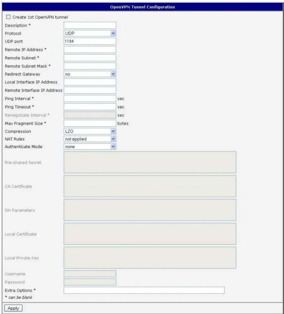
Figure 355: OpenVPN tunnel conguraon
Example of the OpenVPN tunnel conguraon:
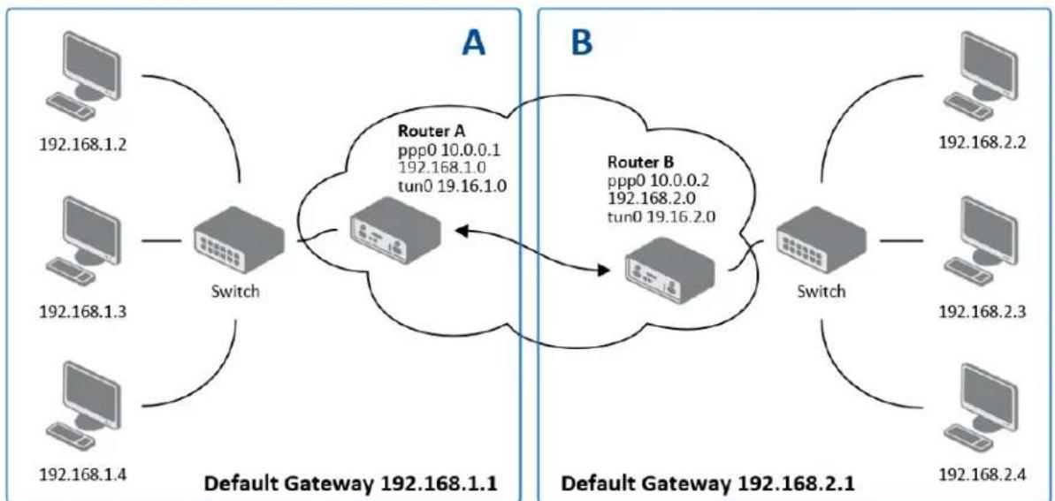
flowchart
graph TD
    subgraph_A["Default Gateway 192.168.1.1"]
        A1["Computer 192.168.1.2"] --> Switch["Switch"]
        A2["Computer 192.168.1.3"] --> Switch
        A3["Computer 192.168.1.4"] --> Switch
    end
    subgraph_B["Default Gateway 192.168.2.1"]
        B1["Computer 192.168.2.2"] --> Switch2["Switch"]
        B2["Computer 192.168.2.3"] --> Switch2
        B3["Computer 192.168.2.4"] --> Switch2
    end
    Switch --> R["Router A: ppp0 10.0.0.1, 192.168.1.0, tun0 19.16.1.0"]
    Switch2 --> R
    R --> B
    R --> B
    style A fill:#f9f,stroke:#333
    style B fill:#bbf,stroke:#333
Figure 366: Topology of example OpenVPN conguraon
OpenVPN tunnel conguraon:
Table 323: Example of OpenVPN conguraon
| Conguraon | A | B |
| Protocol | UDP | UDP |
| UDP Port | 1194 | 1194 |
| Remote IP Address | 10.0.0.2 | 10.0.0.1 |
| Remote Subnet | 192.168.2.0 | 192.168.1.0 |
| Remote Subnet Mask | 255.255.255.0 | 255.255.255.0 |
| Local Interface IP Address | 19.16.1.0 | 19.16.2.0 |
| Remote Interface IP Address | 19.16.2.0 | 19.18.1.0 |
| Compression | LZO | LZO |
| Authencate mode | none | none |
Examples of dierent opons for conguraon and authencaon of OpenVPN can be found in OpenVPN's tunnel conguraon manuals.
IPSEC TUNNE L CONFIGURATION
Select the IPsec item in the menu to congregate an IPsec tunnel. IPsec is a protocol which is used to create a secure conncon between two LANs. Up to 4 IPsec tunnels may be created.
Table 334: Overview IPsec tunnels
| Item | Descripon |
| Create | This item enables the individual tunnels. |
| Descripon | This item displays the name of the tunnel specied in the conguraon of the tunnel. |
| Edit | Select to congure an IPsec tunnel. |

Figure 377: IPsec tunnels conguraon
Table 345: IPsec tunnel conguraon
| Item | Descripon |
| Descripon | Descripon of tunnel. |
| Remote IP Address | IP address or domain name of the remote host. |
| Remote ID | Idencaon of remote host. The ID contains two parts: a hostname and a domain-name. |
| Remote Subnet | Remote Subnet address |
| Remote Subnet Mask | Remote Subnet mask |
| Local ID | Idencaon of local host. The ID contains two parts: a hostname and a domain-name. |
| Local Subnet | Local subnet address |
| Local subnet mask | Local subnet mask |
| Encapsulaon | IPsec mode – you can choose tunnel or transport |
| NAT Traversal | If address translaon between two end points of the IPsec tunnel is used, it needs to allow NAT Traversal |
| IKE Mode | Denes mode for establishing conncon (main or aggressive).If the aggressive mode is selected, establishing of IPsec tunnel will be faster, but encrypon will set permanently on 3DES-MD5. |
| IKE Algorithm | Way of algorithm selecon:Auto – encrypon and hash alg. Are selected automacallyManual – encrypon and hash alg. Are dened by the user |
| IKE Encrypon | Encrypon algorithm – 3DES, AES128, AES192, AES256 |
| IKE Hash | Hash algorithm – MD5 or SHA1 |
| IKE DH Group | Die-Hellman groups determine the strength of the key used in the key exchange process. Higher group numbers are more secure,but require additional me to compute the key. Group with higher number provides more security, but requires more processing me. |
| ESP Algorithm | Way of algorithm selecon:auto – encrypon and hash alg. are selected automacallymanual – encrypon and hash alg. are dened by the user |
| ESP Encrypon | Encrypon algorithm – DES, 3DES, AES128, AES192, AES256 |
| ESP Hash | Hash algorithm – MD5 or SHA1 |
| PFS | Ensures that derived session keys are not compromised if one of the private keys is compromised in the future |
| PFS DH Group | Die-Hellman group number (see IKE DH Group) |
| Key Lifetime | Lifetime key data part of tunnel. The minimum value of this parameter is 60s. The maximum value is 86400s. |
| IKE Lifetime | Lifetime key service part of tunnel. The minimum value of this parameter is 60s. The maximum value is 86400s. |
| Rekey Margin | Species how long before conncon expiry should aempt to negotiate a replacement begin. The maximum value must be less than half the parameters IKE and Key Lifetime. |
| Rekey Fuzz | Species the maximum percentage by which should be randomly increased to randomize re-keying intervals |
| DPD Delay | Denes me aer which is made IPsec tunnel vericaon |
| DPD Timeout | By parameter DPD Timeout is set meout of the answer |
| Authencate Mode | By this parameter can be set authencaon:Pre-shared key – shared key for both o-side tunnel.X.509 Cercate – allows X.509 cercation in mulclient mode |
| Pre-shared Key | Sharable key for both pares tunnel. |
| CA Cercate | This cercate is necessary to insert Authencaon mode x.509. |
| Remote Cercate | This cercate is necessary to insert Authencaon mode x.509. |
| Local Cercate | This cercate is necessary to insert Authencaon mode x.509. |
| Local Private Key | This private key is necessary to insert Authencaon mode x.509. |
| Local Passphrase | This Local Passphrase is necessary to insert Authencaon mode x.509. |
| Extra Opons | Use this parameter to dene additional parameters of the IPsec tunnel, for example secure parameters etc. |
The cercates and private keys have to be in PEM format.
The random me, aer which it will exchange new keys, is dened as follows:
Lifetime - (Rekey margin + random value in range (from 0 to Rekey margin * Rekey Fuzz/100))
By default, the me for the exchange of keys is between:
• Minimum me: 1h - (9m + 9m) = 42m
• Maximum me: 1h - (9m + 0m) = 51m
In most cases, the sengs should be le at their default values.
| IPsec Tunnel Configuration | ||
| □ Create 1st IPsec tunnel | ||
| Description * | ||
| Remote IP Address * | ||
| Remote ID * | ||
| Remote Subnet * | ||
| Remote Subnet Mask * | ||
| Local ID * | ||
| Local Subnet * | ||
| Local Subnet Mask * | ||
| Encapsulation Mode | tunnel | ▼ |
| NAT Traversal | disabled | ▼ |
| IKE Mode | main | ▼ |
| IKE Algorithm | auto | ▼ |
| IKE Encryption | 3DES | ▼ |
| IKE Hash | MD5 | ▼ |
| IKE DH Group | 2 | ▼ |
| ESP Algorithm | auto | ▼ |
| ESP Encryption | DES | ▼ |
| ESP Hash | MD5 | ▼ |
| PFS | disabled | ▼ |
| PFS DH Group | 2 | ▼ |
| Key Lifetime | 3600 | sec |
| IKE Lifetime | 3600 | sec |
| Rekey Margin | 540 | sec |
| Rekey Fuzz | 100 | % |
| DPD Delay * | sec | |
| DPD Timeout * | sec | |
| Authenticate Mode | pre-shared key | ▼ |
| Pre-shared Key | ||
| CA Certificate | ||
Figure 388: IPsec tunnel conguraon
Example of IPSec Tunnel conguraon:
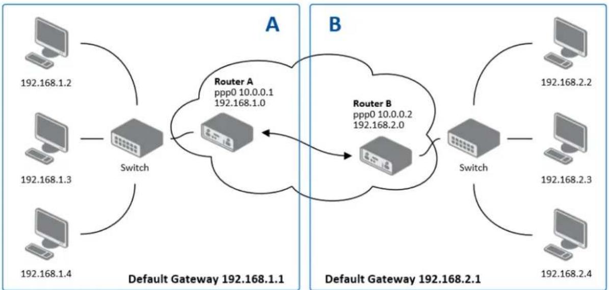
flowchart
graph TD
    subgraph_A["Default Gateway 192.168.1.1"]
        A1["Computer 192.168.1.2"] --> Switch
        A2["Computer 192.168.1.3"] --> Switch
        A3["Computer 192.168.1.4"] --> Switch
    end
    subgraph_B["Default Gateway 192.168.2.1"]
        B1["Computer 192.168.2.2"] --> Switch
        B2["Computer 192.168.2.3"] --> Switch
        B3["Computer 192.168.2.4"] --> Switch
    end
    Switch --> RouterA["Router A ppp0 10.0.0.1 192.168.1.0"]
    Switch --> RouterB["Router B ppp0 10.0.0.2 192.168.2.0"]
    RouterA <--> RouterB
    RouterB <--> Switch
Figure 399: Example 8 - Network topology for IPsec tunneling
IPsec tunnel conguraon:
Table 356: Example 8 - IPsec conguraon
| Conguraon | A | B |
| Remote IP Address | 10.0.0.2 | 10.0.0.1 |
| Remote Subnet | 192.168.2.0 | 192.168.1.0 |
| Remote Subnet Mask | 255.255.255.0 | 255.255.255.0 |
| Local Subnet | 192.168.1.0 | 192.168.2.0 |
| Local Subnet Mask: | 255.255.255.0 | 255.255.255.0 |
| Authencate mode | pre-shared key | pre-shared key |
| Pre-shared key | test | test |
Examples of the dierent opons for conguraon and authencaon of IPsec can be found in the IPsec tunnel conguraon manual.
GRE TUNNELS CONFIGURATION
Select the GRE item in the menu to congregate a GRE tunnel. GRE is a protocol which is used to create an unencrypted conncon between two LANs. Up to 4 GRE tunnels may be created.
Table 367: Overview GRE tunnels
| Item | Descripon |
| Create | This item enables the individual tunnels. |
| Descripon | This item displays the name of the tunnel specied in the conguraon of the tunnel. |
| Edit | Congure the GRE tunnel. |
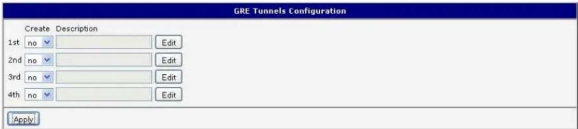
Figure 400: GRE tunnels conguraon
Table 378: GRE tunnel conguraon
| Item | Descripon |
| Descripon | Descripon of tunnel. |
| Remote IP Address | IP address of the remote side of the tunnel |
| Local Interface IP Address | IP address of the local side of the tunnel |
| Remote Interface IP Address | IP address of the remote side of the tunnel |
| Remote Subnet | IP address of the network behind the remote side of the tunnel |
| Remote Subnet Mask | Subnet Mask of the network behind the remote side of the tunnel |
| Pre-shared Key | An oponal value that denes a 32 bit shared key for data encrypon. This key must be the same on both routers. |
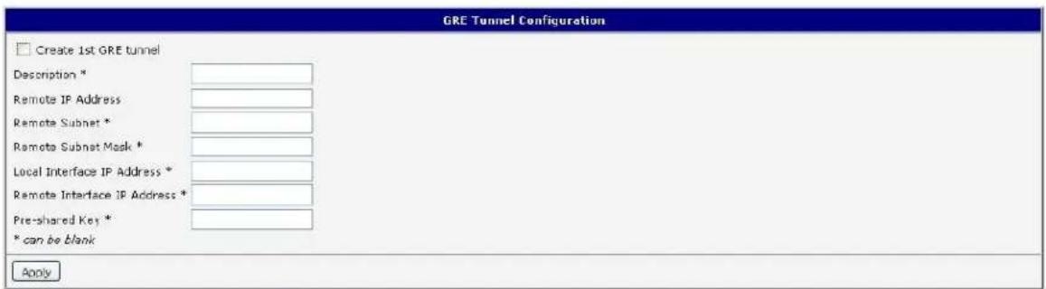
Figure 411: GRE tunnel conguraon
Example of the GRE Tunnel conguraon:
flowchart
graph TD
    subgraph_A["Default Gateway 192.168.1.1"]
        A1["Computer 192.168.1.2"] --> Switch
        A2["Computer 192.168.1.3"] --> Switch
        A3["Computer 192.168.1.4"] --> Switch
    end
    subgraph_B["Default Gateway 192.168.2.1"]
        B1["Computer 192.168.2.2"] --> Switch
        B2["Computer 192.168.2.3"] --> Switch
        B3["Computer 192.168.2.4"] --> Switch
    end
    Switch --> RouterA["Router A ppp0 10.0.0.1 eth0 192.168.1.1"]
    Switch --> RouterB["Router B ppp0 10.0.0.2 eth0 192.168.2.1"]
    RouterA <--> RouterB
    RouterB <--> Switch
Figure 422: Network topology for GRE tunneling
GRE tunnel Conguraon:
Table 389: Example 9 - GRE tunnel conguraon
| Conguraon | A | B |
| Remote IP Address | 10.0.0.2 | 10.0.0.1 |
| Remote Subnet | 192.168.2.0 | 192.168.1.0 |
| Remote Subnet Mask | 255.255.255.0 | 255.255.255.0 |
L2TP TUNNEL CONFIGURATION
Select the L2TP item in the menu to congregate an L2TP tunnel. L2TP is a protocol which is used to create an unencrypted conncon between two LANs. Only one L2TP tunnel may be created.
Table 4039: L2TP tunnel conguraon
| Item | Descripon |
| Mode | L2TP tunnel mode on the router side• L2TP server - For a server, you must dene the start and end IP address range oered by the server• L2TP client – For a client, you must enter the IP address of the server |
| Server IP Address | IP address of server |
| Client Start IP Address | Start IP address in range, which is oered by server to clients |
| Client End IP Address | End IP address in range, which is oered by server to clients |
| Local IP Address | IP address of the local side of the tunnel |
| Remote IP Address | IP address of the remote side of the tunnel |
| Remote Subnet | Address of the network behind the remote side of the tunnel |
| Remote Subnet Mask | The mask of the network behind the remote side of the tunnel |
| Username | Username for login to L2TP tunnel |
| Password | Password for login to L2TP tunnel |
Press the Apply buon to apply changes.
Figure 433: L2TP tunnel conguraon
Example of the L2TP Tunnel conguraon:
flowchart
graph TD
    subgraph_A["Default Gateway 192.168.1.1"]
        A1["Computer 192.168.1.2"] --> Switch["Switch"]
        A2["Computer 192.168.1.3"] --> Switch
        A3["Computer 192.168.1.4"] --> Switch
    end
    subgraph_B["Default Gateway 192.168.2.1"]
        B1["Computer 192.168.2.2"] --> Switch2["Switch"]
        B2["Computer 192.168.2.3"] --> Switch2
        B3["Computer 192.168.2.4"] --> Switch2
    end
    Switch --> R["Router A\npp0 10.0.0.1\n192.168.1.1"]
    Switch2 --> R
    R --> B
    R --> B2
    R --> B3
Figure 444: Example 10 - Network topology for L2TP tunneling
Conguraon of the L2TP tunnel:
Table 4140: Example 10 - L2TP tunnel conguraon
| Conguraon | A | B |
| Mode | L2TP Server | L2TP Client |
| Server IP Address | --- | 10.0.0.1 |
| Client Start IP Address | 192.168.1.2 | --- |
| Client End IP Address | 192.168.1.254 | --- |
| Local IP Address | 192.168.1.1 | --- |
| Remote IP Address | --- | --- |
| Remote Subnet | 192.168.2.0 | 192.168.1.0 |
| Remote Subnet Mask | 255.255.255.0 | 255.255.255.0 |
| Username | username | username |
| Password | password | password |
PPTP TUNNEL CONFIGURATION
Select the PPTP item in the menu to congregate a PPTP tunnel. PPTP is a protocol which is used to create a secure conncon between two LANs. Only one PPTP tunnel may be created.
Figure 455: PPTP tunnel conguraon
Table 412: PPTP tunnel conguraon
| Item | Descripon |
| Mode | PPTP tunnel mode on the router sidePPTP server – For a server, you must dene the start and end IP address range oered by the serverPPTP client – For a client, you must enter the IP address of the server |
| Server IP Address | IP address of server |
| Local IP Address | IP address of the local side of the tunnel |
| Remote IP Address | IP address of the remote side of the tunnel |
| Remote Subnet | Address of the network behind the remote side of the tunnel |
| Remote Subnet Mask | The mask of the network behind the remote side of the tunnel |
| Username | Username for login to PPTP tunnel |
| Password | Password for login to PPTP tunnel |
Press the Apply buon to apply changes.
Example of the PPTP Tunnel conguraon:
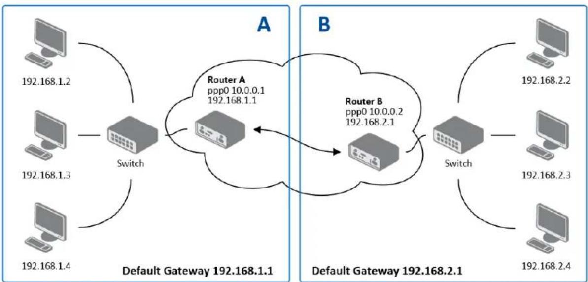
flowchart
graph TD
    subgraph_A["Default Gateway 192.168.1.1"]
        A1["Computer 192.168.1.2"] --> Switch
        A2["Computer 192.168.1.3"] --> Switch
        A3["Computer 192.168.1.4"] --> Switch
    end
    subgraph_B["Default Gateway 192.168.2.1"]
        B1["Computer 192.168.2.2"] --> Switch
        B2["Computer 192.168.2.3"] --> Switch
        B3["Computer 192.168.2.4"] --> Switch
    end
    Switch --> RouterA["Router A ppp0 10.0.0.1\n192.168.1.1"]
    Switch --> RouterB["Router B ppp0 10.0.0.2\n192.168.2.1"]
    RouterA <--> RouterB
    RouterB <--> Switch
Figure 466: Example 11 - Network topology for PPTP tunneling conguraon
Conguraon of the PPTP tunnel:
Table 423: Example 11 - PPTP tunnel conguraon
| Conguraon | A | B |
| Mode | PPTP Server | PPTP Client |
| Server IP Address | --- | 10.0.0.1 |
| Local IP Address | 192.168.1.1 | --- |
| Remote IP Address | --- | --- |
| Remote Subnet | 192.168.2.0 | 192.168.1.0 |
| Remote Subnet Mask | 255.255.255.0 | 255.255.255.0 |
| Username | username | username |
| Password | password | password |

DYNDNS CLIENT CONFIGURATION
For Dynamic DNS to funcon properly, the router's SIM card must have a public IP address assigned.
The router supports DynamicDNS using a DNS server on www.dyndns.org. DynDNS client Conguraon can be called up by selecng opon DynDNS item in the menu.
Table 434: DynDNS conguraon
| Item | Descripon |
| Hostname | Third order domain registered on server www.dyndns.org |
| Username | Username for login to DynDNS server |
| Password | Password for login to DynDNS server |
| Server | If you want to use a dierent DynDNS service than www.dyndns.org, enter the update server service in this parameter. If this item is le blank, the router uses the default server members.dyndns.org. |
Example of the DynDNS client conguraon with domain conel.dyndns.org:
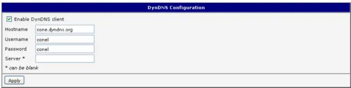
Figure 477: Example of DynDNS conguraon
NTP CLIENT CONFIGURATION
NTP (Network Time Protocol) allows the router to set its internal clock using a network me server. The NTP client Conguraon can be called up by selecng opon NTP item in the menu.
If opon Enable local NTP service is selected, the router will funcon as an NTP server for other devices on the LAN.
Table 445: NTP conguraon
| Item | Descripon |
| Primary NTP Server Address | IP or domain address primary NTP server. |
| Secondary NTP Server Address | IP or domain address secondary NTP server. |
| Timezone | Sets the me zone of the router |
| Daylight Saving Time | Dene me shi:No - me shi is disabledYes - me shi is allowed |
Example of the NTP conguraon with primary (ntp.cesnet.cz) and secondary (k.cesnet.cz) NTP servers and with daylight saving me:
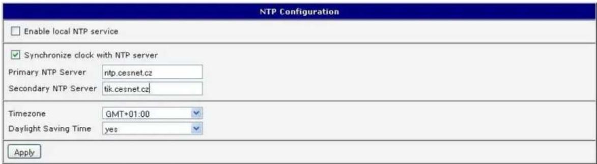
Figure 488: Example of NTP conguraon
SNMP CONFIGURATION
SNMP (Simple Network Management Protocol) provides status informaon about network elements such as routers or end computers. The router supports SNMP agent v1/v2 or v3 which sends informaon about the router and its expansion ports. To enter the SNMP Conguraon, select the SNMP item from the conguraon menu.
Table 456: SNMP agent conguraon
| Item | Descripon |
| Name | Designaon of the router. |
| Locaon | Locaon of the router. |
| Contact | Person who manages the router together with informaon how to contact this person. |
Enable SNMPv1/v2 with the Enable SNMPv1/v2 access item. You will need to denote a password for access to the SNMP agent (Community). "Public" is commonly used.
The Enable SNMPv3 access item allows you to enable SNMPv3. Then you must denote the following parameters:
Table 467: SNMPv3 conguraon
| Item | Descripon |
| Username | User Name |
| Authencaon | Encrypon algorithm on the Authencaon Protocol that is used to ensure the identity of users. |
| Authencaon Password | Password used to generate the key used for authencaon. |
| Privacy | Encrypon algorithm on the Privacy Protocol that is used to ensure condenality of data. |
| Privacy Password | Password for encrypon on the Privacy Protocol. |
In addition, you can connue with this conguraon:
- By choosing Enable I/O extension upon to monitor the binary input (I/O) on the router.
- By choosing Enable XC-CNT extension to monitor the status of the expansion port CNT inputs and outputs.
- By choosing Enable M-BUS extension and enter the Baud Rate, Parity and Stop Bits it is possible to monitor the meter status connected to the expansion port MBUS status.
Table 478: SNMP conguraon (MBUS extension)
| Item | Descripon |
| Baud rate | Communicaon speed. |
| Parity | Control parity bit:none – Data will be sent without parity.even – Data will be sent with even parity.odd - Data will be sent with odd parity. |
| Stop Bits | Number of stop bits. |

Parameters Enable XC-CNT extension and Enable M-BUS extension cannot be checked together.
By choosing Enable reporting to supervisor system and entering the IP Address and Period it is possible to send stascal informaon to the monitoring system, R-SeeNet.
Table 489: SNMP conguraon (R-SeeNet)
| Item | Descripon |
| IP Address | IP address |
| Period | Period of sending stascal informaon (in minutes) |
Every monitor value is uniquely idened by a number idener OID (Object Idener). For the binary input and output the following range of OIDs is used:
Table 490: Object idener for binary input and output
| OID | Descripon |
| .1.3.6.1.4.1.30140.2.3.1.0 | Binary input BIN0 (values 0,1) |
| .1.3.6.1.4.1.30140.2.3.2.0 | Binary output OUT0 (values 0,1) |
For the expansion port CNT, the following range of OID is used:
Table 501: Object idener for CNT port
| OID | Descripon |
| .1.3.6.1.4.1.30140.2.1.1.0 | Analogy input AN1 (range 0-4095) |
| .1.3.6.1.4.1.30140.2.1.2.0 | Analogy input AN2 (range 0-4095) |
| .1.3.6.1.4.1.30140.2.1.3.0 | Counter input CNT1 (range 0-4294967295) |
| .1.3.6.1.4.1.30140.2.1.4.0 | Counter input CNT2 (range 0-4294967295) |
| .1.3.6.1.4.1.30140.2.1.5.0 | Binary input BIN1 (values 0,1) |
| .1.3.6.1.4.1.30140.2.1.6.0 | Binary input BIN2 (values 0,1) |
| .1.3.6.1.4.1.30140.2.1.7.0 | Binary input BIN3 (values 0,1) |
| .1.3.6.1.4.1.30140.2.1.8.0 | Binary input BIN4 (values 0,1) |
| .1.3.6.1.4.1.30140.2.1.9.0 | Binary output OUT1 (values 0,1) |
Table 512: Object idener for M-BUS port
| OID | Descripon |
| .1.3.6.1.4.1.30140.2.2.<address>.1.0 | IdNumber – meter number |
| .1.3.6.1.4.1.30140.2.2.<address>.2.0 | Manufacturer |
| .1.3.6.1.4.1.30140.2.2.<address>.3.0 | Version – specied meter version |
| .1.3.6.1.4.1.30140.2.2<address>.4.0 | Medium – type of metered medium |
| .1.3.6.1.4.1.30140.2.2<address>.5.0 | Status – errors report |
| .1.3.6.1.4.1.30140.2.2<address>.6.0 | 0. VIF – value informaon eld |
| .1.3.6.1.4.1.30140.2.2<address>.7.0 | 0. measured value |
| .1.3.6.1.4.1.30140.2.2<address>.8.0 | 1. VIF – value informaon eld |
| .1.3.6.1.4.1.30140.2.2<address>.9.0 | 1. measured value |
| .1.3.6.1.4.1.30140.2.2<address>.10.0 | 2. VIF – value informaon eld |
| .1.3.6.1.4.1.30140.2.2<address>.11.0 | 2. measured value |
| .1.3.6.1.4.1.30140.2.2<address>.12.0 | 3. VIF – value informaon eld |
| .1.3.6.1.4.1.30140.2.2<address>.13.0 | 3. measured value |
| . | . |
| . | . |
| . | . |
| .1.3.6.1.4.1.30140.2.2<address>.100.0 | 47. VIF – value informaon eld |
| .1.3.6.1.4.1.30140.2.2<address>.101.0 | 47. measured value |
The meter address can be from range 0..254 when 254 is broadcast.
Since rmware 3.0.4 all v2 routers with board RB-v2-6 and newer provide informaon about the internal temperature of the device (OID 1.3.6.1.4.1.30140.3.3) and power voltage (OID 1.3.6.1.4.1.30140.3.4).
Example of SNMP sengs and readout:
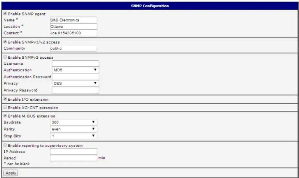
Figure 499. Example of SNMP conguraon
![MG-SOFT MIB Browser Professional Edition File Edit View SNMP Action Tools Window Help Query MIB Ping Remote SNMP agent 192.168.2.250 Split Vertical MIB tree MIB Tree ccitt iso org dod internet directory mgmt mib-2 system sysDescr sysObjectID sysUpTime sysContact sysName sysLocation Response results Remote address: 192.168.2.250 port: 161 transport: IP/UDP Local address: 192.168.2.115 port: 4915 transport: IP/UDP Protocol version: SNMPv1 Operation: Get Request binding: 1: sysLocation.0 (DisplayString) null Response binding: 1: sysLocation.0 (DisplayString) Usti nad Otlioi [55.73.74.69.20.6E.61.64.20.4F.72.6C.69.63.69 (hex)] OID 1.3.6.1.2.1.1.4 SNMPv1](/content/2026/06/1187196/images/351b01f4da31e9e89ac3596233498b291b1e200b1feb993d415b0c713b88a684.jpg)
Figure 500. Example of the MIB browser
It is important to set the IP address of the SNMP agent (router) in the eld Remote SNMP agent. Aer entering the IP address, it is possible show object ideners.
The path to the objects is:
iso->org->dod->internet->private->enterprises->conel->protocols.
The path to informaon about the router is:
iso->org->dod->internet->mgmt->mib-2->system
SMTP CONFIGURATION
The SMTP (Simple Mail Transfer Protocol) client is used to send emails.
Table 523: SMTP client conguraon
| Item | Descripon |
| SMTP Server Address | IP or domain address of the mail server. |
| Username | Name to email account. |
| Password | Password to email account. |
| Own Email Address | Address of the sender. |
The mobile operator may block other SMTP servers. If this occurs, then you must use the SMTP server of the operator.
Example sengs for the SMTP client:
| SMTP Configuration | |
| SMTP Server Address | smtp.domain.com |
| Username | name@domain.com |
| Password | pass |
| Own Email Address | name@domain.com |
| Apply | |
Figure 511. SMTP conguraon
An E-mail can be sent from the Startup script. The following command is used to send emails with following parameters.
- -t receiver Email address
- -s subject
- -m message
- -a appendix
- -r number of aempts to send email (default set 2 aempts)
Commands and parameters can be entered only in lowercase.

Example to send email:
email -t name@domain.com -s "subject"-m "message"-a c:\directory\abc.doc -r 5
This command sends an e-mail message to address jack@google.com with the subject "subject", body message "message" and annex "abc.doc" right from the directory c:\directory\ and will aempt 5 mes to send the message.
SMS CONFIGURATION
Note: The SPECTRE RT industrial router does not support SMS messaging conguraon.
The SPECTRE cellular router can automatically send SMS messages to a cell phone or SMS message server when certain events occur. The SMS Conguraon page allows the user to select which events will generate an SMS message.
Table 534: Send SMS conguraon
| Item | Descripon |
| Send SMS on power up | Send an SMS message when the router powers up |
| Send SMS on mobile network connect | Send an SMS message when the mobile network conncon is acve. |
| Send SMS on mobile network disconnect | Send an SMS message on mobile network disconncon. |
| Send SMS when datalimit exceeded | Send an SMS message when the data limit is exceeded. |
| Send SMS when binary input on I/O port (BIN0) is acve | Send an SMS message when the binary input on the I/O port (BIN0) goes acve. The text of the message is set using parameter BIN0. |
| Send SMS when binary input on expansion port (BIN1-BIN4) is acve | Send an SMS message when a binary input on the I/O expansion port (BIN BIN4) is acve. The text of the message is set using parameters BIN1 - BIN4. |
| Add mestamp to SMS | Adds a me stamp to the sent SMS messages. The mestamp has the format YYYY-MM-DD hh:mm:ss. |
| Phone Number 1 | The telephone numbers that the SMS messages will be sent to. |
| Phone Number 2 | |
| Phone Number 3 | |
| Unit ID | The name of the router that is included in the SMS messages. |
| BIN0 - SMS | User-dened Text eld 0 for the SMS messages. |
| BIN1 - SMS | User-dened Text eld 1 for the SMS messages. |
| BIN2 - SMS | User-dened Text eld 2 for the SMS messages. |
| BIN3 - SMS | User-dened Text eld 3 for the SMS messages. |
| BIN4 - SMS | User-dened Text eld 4 for the SMS messages. |
You can also control the funcon of the router by sending SMS messages to the device. The router can be commanded to go online or oine via an SMS message or to switch to the alternate SIM card or provider. The binary outputs can also be set or reset using SMS. The Enable remote control via SMS opon must be selected to enable this feature. Up to three numbers can be congured for incoming SMS messages. If the Enable remote control via SMS opon is set, all incoming SMS messages are processed by the router and deleted.

Table 545: Control via SMS conguraon
| Item | Descripon |
| Phone Number 1 | Allowed phone numbers for incoming SMS messages. |
| Phone Number 2 | |
| Phone Number 3 |

Note: If no phone number is lled in, the router will accept incoming messages from all phone numbers. If any phone numbers are entered into the list, the router will only accept SMS messages which originate from those numbers.
Control SMS messages cannot change the router conguraon. Any changes made to the router by an SMS message will only remain in eect unl the router is restarted. Aer a reboot, the router conguraon will return to the sengs in non-volale memory. For example, if the router is switched oine by an SMS message, the router will remain oine unl the next me it is power cycled or re-booted.
To control the router using SMS, the message text must contain the control command. Table 48 lists the SMS control messages that are supported.
Table 556: SMS control commands
| SMS Control Message | Descripon |
| go online sim 1 | Switch to SIM1 card |
| go online sim 2 | Switch to SIM2 card |
| go online | Switch router in online mode |
| go oine | Mobile network conncon terminaon |
| set out0=0 | Set binary I/O output to 0 |
| set out0=1 | Set binary I/O output to 1 |
| set out1=0 | Set binary output on port 1 to a 0 |
| set out1=1 | Set binary output on port 1 to a 1 |
| set prole std | Set standard prole |
| set prole alt1 | Set alternate prole 1 |
| set prole alt2 | Set alternate prole 2 |
| set prole alt3 | Set alternate prole 3 |
| reboot | Router reboot |
| get ip | Router will send an SMS message back with the IP address from the SIM card. |
You may send and receive SMS messages using either the serial expansion ports or a TCP conncon over the Ethernet network. For serial communicaon, the baud rate must be set to match the aached host. Select opon Enable AT-SMS protocol on expansion port 1 to allow messages to be sent and received using serial port 1.
Table 567: Send SMS on serial PORT1 conguraon
| Item | Descripon |
| Baud rate | Communicaon speed expansion port 1 |
Select opon Enable AT-SMS protocol on expansion port 2 to allow messages to be sent and received using serial port 2.
Table 578: Send SMS on serial PORT2 conguraon
| Item | Descripon |
| Baud rate | Communicaon speed expansion port 2 |
It is also possible to send and receive SMS messages over a TCP/IP conneccon by choosing Enable AT-SMS protocol on TCP port. The TCP port used for sending and receiving SMS messages must be entered into the conguraon eld.
Table 589: Send SMS on Ethernet Port conguraon
| Item | Descripon |
| TCP Port | TCP port on which will be allowed to send/receive SMS messages. |
SEND SMS
Standard AT commands are used to send and receive SMS messages over the serial ports or a TCP conncon. They can be sent to the router using a terminal program such as Hyper Terminal. Aer establishing a conncon with the router via the serial interface or Ethernet, AT commands are used to read and delete incoming messages and send outgoing messages. Table 52 lists the AT commands that are used for sending and receiving SMS messages.
Table 6059: AT commands to send and receive SMS messages
| AT commands | Descripon |
| AT+CGMI | Returns the manufacturer specific identity |
| AT+CGMM | Returns the manufacturer specific model identity |
| AT+CGMR | Returns the manufacturer specific model revision identity |
| AT+CGPADDR | Displays the IP address of the ppp0 interface |
| AT+CGSN | Returns the product serial number |
| AT+CIMI | Returns the International Mobile Subscriber Identity number (IMSI) |
| AT+CMGD | Deletes a message from the location |
| AT+CMGF | Sets the presentation format of short messages |
| AT+CMGL | Lists messages of a certain status from a message storage area |
| AT+CMGR | Reads a message from a message storage area |
| AT+CMGS | Sends a short message from the device to entered tel. Number |
| AT+CMGW | Writes a short message to SIM storage |
| AT+CMSS | Sends a message from SIM storage location value |
| AT+COPS? | Identifies the available mobile networks |
| AT+CPIN | Is used to query and enter a PIN code |
| AT+CPMS | Selects SMS memory storage types, to be used for short message operations |
| AT+CREG | Displays network registration status |
| AT+CSCA | Sets the short message service center (SMSC) number |
| AT+CSCS | Selects the character set |
| AT+CSQ | Returns the signal strength of the registered network |
| AT+GMI | Returns the manufacturer specific identity |
| AT+GMM | Returns the manufacturer specific model identity |
| AT+GMR | Returns the manufacturer specific model revision identity |
| AT+GSN | Returns the product serial number |
| ATE | Determines whether or not the device echoes characters |
ATI
Transmits the manufacturer specific information about the device
In order to send an SMS message, text mode must rst be selected by sending the command AT+CMGF=1 to the router.
Command: AT+CMGF=1
Response: OK
The SMS message is created and sent using the command AT+CMGS="tel. number" where tel. number is the telephone number to send the message to. Aer pressing the Enter buon, the router will respond with a '>' prompt and the text of the SMS message can be entered. Aer entering the text, press CTRL+Z to send the message. It may take a few minutes for the SMS message to be sent depending on the network. You may cancel SMS text input by pressing Esc.
Example: To send "Hello World" to telephone number 712-123-4567
Command: AT+CMGS="7121234567" Press Enter
Response: >
Enter SMS Text: Hello World! Press CTRL+Z (keys combinaon)
Response: OK
To see a list of all incoming messages, type:
Command: AT+CMGL="ALL" Press Enter
Response: +CMGL:
where
REC UNREAD – SMS unread
REC READ - SMS read
STO UNSENT – stored unsent SMS
STO SENT – stored sent SMS
ALL – all SMS messages
Example:
+CMGL: 1, "REC UNREAD", "+420721123456", "08/02/02, 10:33:26+04" Hello World!
To read a single SMS message, use AT+CMGR=
Example:
Command: AT+CMGR=1 Press Enter
Response: +CMGL: 1, "REC READ", "+420721123456", "08/01/12, 9:48:04+04" Hello World!
To delete a received SMS message, use AT+CMGD=
To delete message 1:
Command: AT+CMGD=1 Press Enter
Response: OK
The format of the Router Power-On SMS message is as follows:
Router (Unit ID) has been powered up. Signal strength -xx dBm.
The format of the Router mobile network conneccon SMS message is as follows:
Router (Unit ID) has established conncon to mobile network. IP address xxx.xxx.xxx.xxx
Aer a mobile network disconnect, the router will send an SMS message in the form:
Router (Unit ID) has lost mobile network conncon. IP address xxx.xxx.xxx.xxx
SMS Conguraon Example:
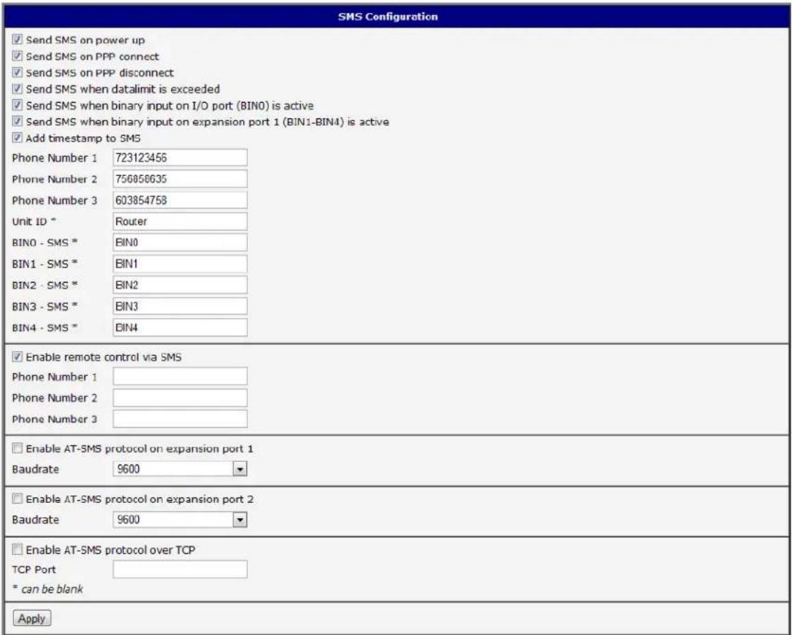
Figure 522. Example of SMS conguraon 1
Router conguraon for sending SMS messages via the serial interface on PORT1:
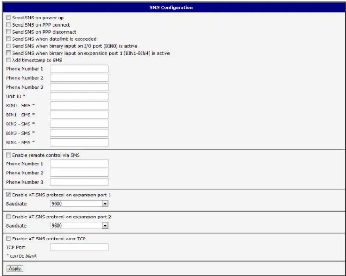
Figure 533. Example of SMS conguraon 2
Example of the router conguraon for accepng SMS messages from every phone number:
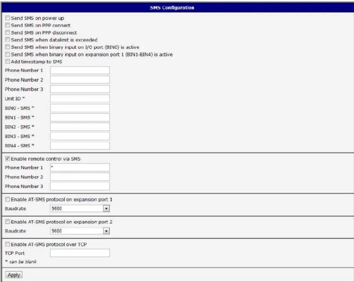
Figure 544. Example of SMS conguraon 3
Example of the router conguraon for accepng SMS messages from two phone numbers:
| SMS Configuration | |
| □ Send SMS on power up □ Send SMS on PPP connect □ Send SMS on PPP disconnect □ Send SMS when datalimit is exceeded □ Send SMS when binary input on I/O port (BIN0) is active □ Send SMS when binary input on expansion port 1 (BIN1-BIN4) is active □ Add timestamp to SMS | |
| Phone Number 1 | |
| Phone Number 2 | |
| Phone Number 3 | |
| Unit ID * | |
| BIN0 - SMS * | |
| BIN1 - SMS * | |
| BIN2 - SMS * | |
| BIN3 - SMS * | |
| BIN4 - SMS * | |
| ✓ Enable remote control via SMS | |
| Phone Number 1 | 728123456 |
| Phone Number 2 | 766254864 |
| Phone Number 3 | |
| □ Enable AT-SMS protocol on expansion port 1 | |
| Baudrate | 9600 |
| □ Enable AT-SMS protocol on expansion port 2 | |
| Baudrate | 9600 |
| □ Enable AT-SMS protocol over TCP | |
| TCP Port | |
| * can be blank | |
| Apply | |
Figure 555. Example of SMS conguraon 4
EXPANSION PORT CON FIGURATION
You may send and receive data from a serial port on Auxiliary Port 1 or 2 using UDP or TCP protocol on the Ethernet network. This feature allows a computer on the network to send data to a serial device as if it was physically connected to the computer. You can also congregate 2 routers to act as a serial port extender where they transmit data transparently across the Ethernet network between 2 serial devices as if the serial devices were cabled together.
You must be using a router which has the RS-232 or RS-485 onpon on Port 1 or 2.
Table 61: Expansion PORT conguraon
| Item | Descripon |
| Baud rate | Communicaton speed. |
| Data Bits | Number of data bits. |
| Parity | Control parity bitnoneevenodd |
| Stop Bits | Number of stop bits. |
| Split Timeout | Inter-character Timeout. If no characters are received within this amount of me, any buered characters will be sent over the Ethernet port. |
| Protocol | Protocol:TCPUDP |
| Mode | Mode of conncon:TCP server - The router will listen for incoming TCP conncon requests.TCP client - The router will connect to a TCP server on the specied IP address and TCP port. |
| Server Address | When set toTCP clientabove, it is necessary to enter theServer addressandTCP port. |
| TCP Port | The TCP port for conncons. |
If the Check TCP connection is selected, the router will automatically send TCP keep-alive messages to verify that the conneccon is sll valid.
Table 602: TCP Keep-Alive conguraon
| Item | Descripon |
| Keepalive Time | Time between sending keep-alive packets |
| Keepalive Interval | Keep-alive Response Titimeout |
| Keepalive Probes | Number of aempts before conneccon is down |
It the opon Use CD as indicator of the TCP conncon is selected, the router will acvate the DTR output when a TCP conncon is acve.
Table 613: CD signal descripon
| CD | Descripon |
| Acve | TCP conncon is on |
| Nonacve | TCP conncon is o |
Select Use DTR as control of TCP conneccon to use DTR to control when TCP conneccons are allowed. (CD on the router).
Table 624: DTR signal descripon
| DTR | Descripon server | Descripon client |
| Acve | The router will accept a TCP conncon. | Router creates a TCP conncon. |
| Nonacve | The router does not accept incoming TCP conncons. | Router ends the TCP conncon. |
Press the Apply buon to apply changes.
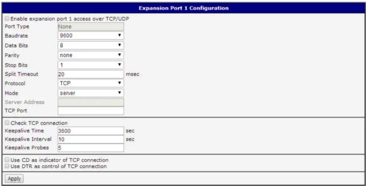
Figure 56. Expansion port conguraon
Example of external port conguraon:
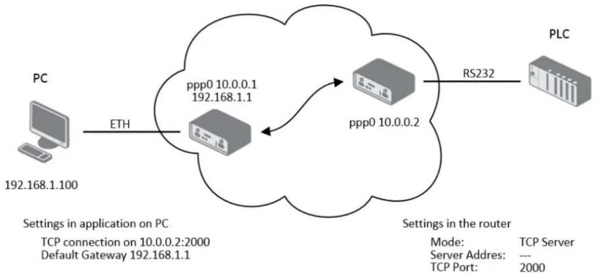
flowchart
graph LR
    PC["PC\n192.168.1.100"] -->|ETH| Server1["Server"]
    Server1 -->|ppp0 10.0.0.1\n192.168.1.1| Server2["Server"]
    Server2 -->|ppp0 10.0.0.2| Router["Router"]
    Router -->|RS232| PLC["PLC"]
    subgraph Settings in application on PC
        TCP1["TCP connection on 10.0.0.2:2000\nDefault Gateway 192.168.1.1"]
    end
    subgraph Settings in the router
        ModeMode["Mode: TCP Server"]
        ServerAddress["Server Address: ---"]
        TCPPort["TCP Port: 2000"]
    end
Figure 577. example of Ethernet to serial communicaon
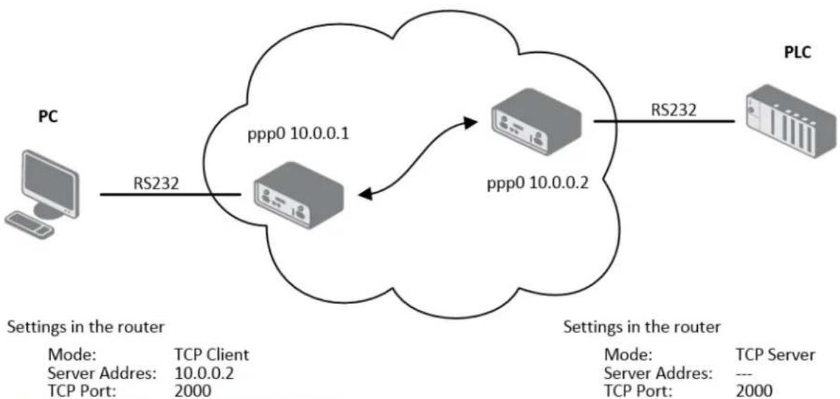
flowchart
graph LR
    PC["PC"] -->|RS232| Router1["Router"]
    Router1 -->|ppp0 10.0.0.1| Router2["Router"]
    Router2 -->|ppp0 10.0.0.2| Router3["Router"]
    Router3 -->|RS232| PLC["PLC"]
    subgraph Router1
        Router1 -->|Settings in the router| PC
        Router2 -->|Settings in the router| PC
    end
    subgraph Router2
        Router2 -->|Settings in the router| PLC
    end
    subgraph PLC
        PLC -->|Settings in the router| PC
    end
Figure 588. Example of serial port extension
USB PORT CONFIGURATION
Select the USB Port item in the conguraon menu to bring up the USB conguraon page. A USB to RS-232 converter can be used to send data out of the serial port from the Ethernet network in the same manner as the RS-232 expansion port opons.
Table 635: USB port conguraon 1
| Item | Descripon |
| Baud rate | Applied communicaon speed. |
| Data Bits | Number of data bits. |
| Parity | Control parity bitnoneevenodd |
| Stop Bits | Number of stop bit. |
| Split Timeout | Inter-character Timeout (ms). If no characters are received within this amount of me, any buered characters will be sent out of the USB port. |
| Protocol | Communicaon protocol:TCP - communicaon using a linked protocol TCPUDP - communicaon using a unlinked protocol UDP |
| Mode | Mode of conncon:TCP server - The router will listen to incoming requests regarding the TCP conncon.TCP client - The router will connect to a TCP server on the specied IP address and TCP port. |
| Server Address | In mode TCP client it is necessary to enter the Server address and nal TCP port. |
| TCP Port | In both modes of conncon it is necessary to specify the TCP port on which the router will communicate TCP conncons. |
If the Check TCP conncon is selected, the router will automatically send TCP keep-alive messages to verify that the conncon is sll valid.
Table 646: USB port conguraon 2
| Item | Descripon |
| Keepalive Time | Time between sending keep-alive packets |
| Keepalive Interval | Keep-alive Response Titimeout |
| Keepalive Probes | Number of aempts before conneccon is down |
It the opon Use CD as indicator of the TCP conncon is selected, the router will acvate the DTR output when a TCP conncon is acute.
Table 657: CD signal descripon
| CD | Descripon |
| Acve | TCP conncon is on |
| Nonacve | TCP conncon is o |
Select Use DTR as control of TCP conneccon to use DTR to control when TCP conneccons are allowed. (CD on the router).
Table 668: DTR signal descripon
| DTR | Descripon server | Descripon client |
| Acve | The router will accept a TCP conncon. | Router creates a TCP conncon. |
| Nonacve | The router does not accept incoming TCP conncons. | Router ends the TCP conncon. |
Supported USB/RS-232 converters:
• FTDI
- Prolic PL2303
• Silicon Laboratories CP210×
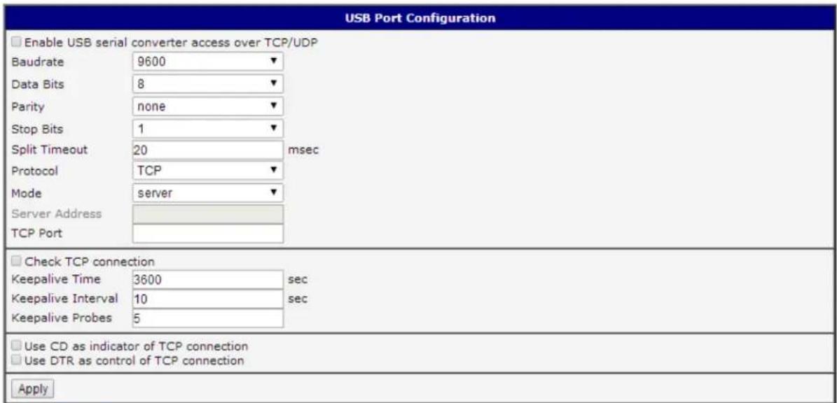
Figure 599. USB conguraon
Example of USB port conguraon:
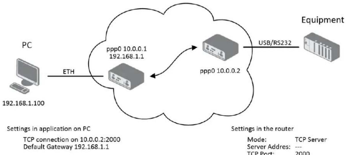
flowchart
graph LR
    PC["PC\n192.168.1.100"] -->|ETH| Server1["Server"]
    Server1 -->|ppp0 10.0.0.1\n192.168.1.1| Server2["Server"]
    Server2 -->|ppp0 10.0.0.2| Router["Router"]
    Router -->|USB/RS232| Equipment["Equipment"]
    subgraph Settings in application on PC
        TCP1["TCP connection on 10.0.0.2:2000\nDefault Gateway 192.168.1.1"]
    end
    subgraph Settings in the router
        Mode2["Mode: TCP Server\nServer Adres: ---\nTCP Port: 2000"]
    end
Figure 600. Example of Ethernet to serial using USB port
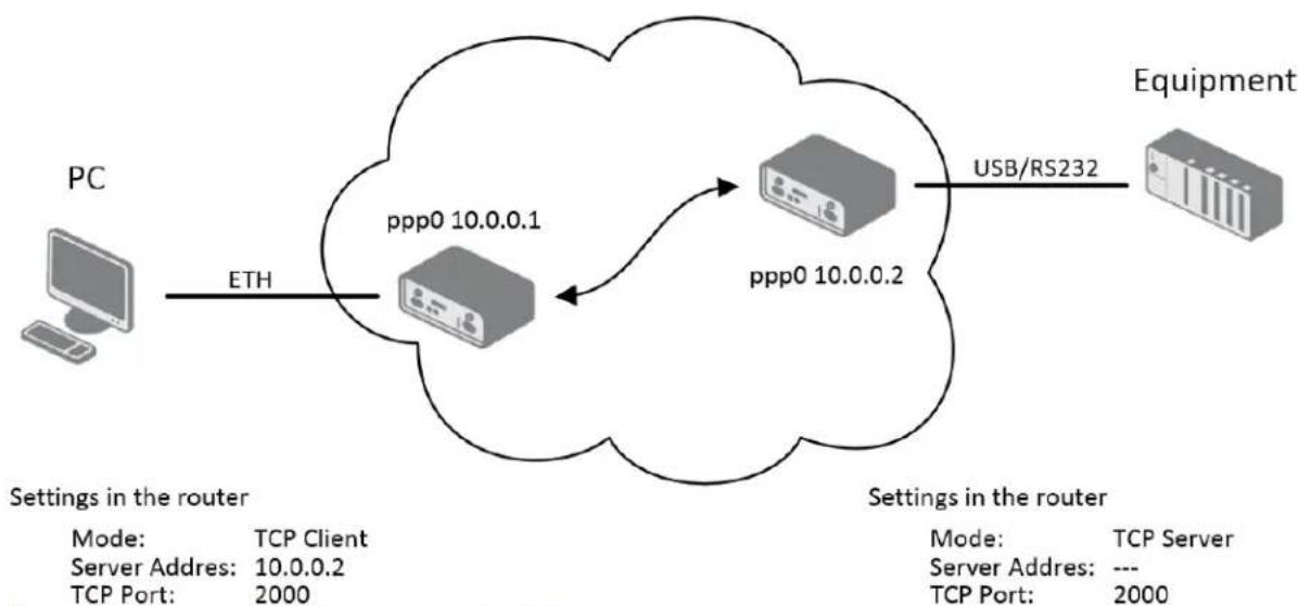
flowchart
graph LR
    PC["PC"] -->|ETH| ServerIP["Server IP"]
    ServerIP -->|ppp0 10.0.0.1| ServerIP2["Server IP"]
    ServerIP2 -->|ppp0 10.0.0.2| ServerIP3["Server IP"]
    ServerIP3 -->|USB/RS232| Equipment["Equipment"]
    subgraph Settings in the router
        direction TB
        PC -->|Settings in the router| ServerIP
        ServerIP2 -->|Settings in the router| ServerIP3
        DevicePort1["PC"] -->|Mode: TCP Client\nServer Adres: 10.0.0.2\nTCP Port: 2000| ServerIP
        DevicePort2["PC"] -->|Mode: TCP Server\nServer Adres: ---\nTCP Port: 2000| ServerIP3
    end
Figure 611. Example of serial extension using USB port
STARTUP SCRIPT
Use the Startup Script window to create your own scripts which will be executed aer all of the inializaon scripts are run.
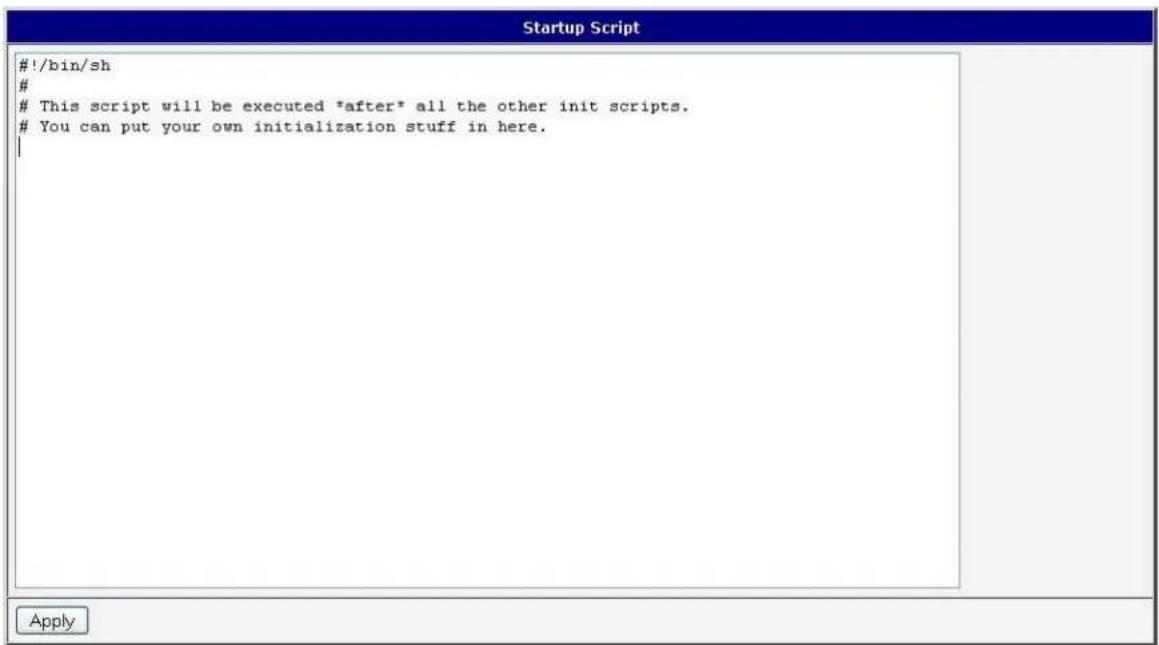
Figure 622. Startup script
Any changes to the startup scripts will take eect the next me the router is power cycled or rebooted.
Example of Startup script: When the router starts up, stop syslogd program and start syslogd with remote logging on address 192.168.2.115 and limited to 100 entries.
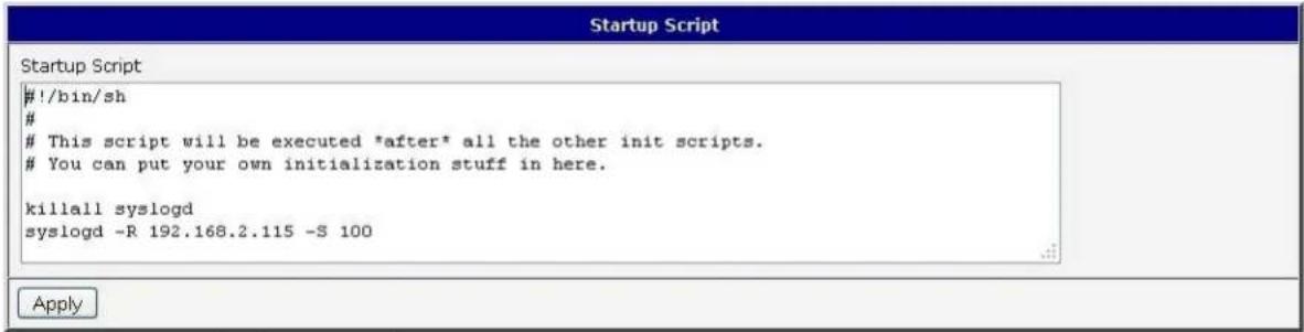
Figure 633. Example of startup script
UP/DOWN SCRIPT
Use the Up/Down Script window to create scripts which will run when the PPP conncon is started or goes down. Any scripts entered into the Up script window will run aer a PPP/WAN conncon is established. Script commands entered into the Down Script window will run when the PPP/WAN conncon is lost.
Figure 644. Up/Down script
Example of UP/Down script: Aer establishing or losing a PPP conncon, the router sends an email with informaon about the PPP conncon.
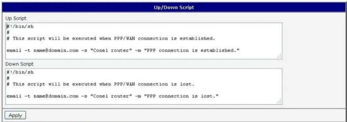
Figure 655. Example of Up/Down script
AUTOMATIC UPDATE CONFIGURATION
The SPECTRE router can be congured to automatically check for rmware updates from an FTP site or a web server and update its rmware or conguraon informaon. Use the Automac update menu to congure the automac update sengs. It is also possible to update the conguraon and rmware through the USB host connector of the router.
If the Enable automac update of conguraon opon is selected, the router will check if there is a conguraon le on the remote server, and if the conguraon in the le is dierent than its current conguraon, it will update its conguraon to the new sengs and reboot. If the Enable automac update of rmware opon is checked, the router will look for a new rmware le and update its rmware if necessary.
Table 679: Automac update conguraon
| Item | Descripon |
| Source | Select the locaon of the update les:HTTP/FTP server – Remote le server.USB ash drive - Router will check for rmware or conguraon les in the root directory of the connected USB device.Both – Router will check for new rmware or conguraon les in both places. |
| Base URL | Base URL or IP address from which the conguraon le will be downloaded. |
| Unit ID | Name of conguraon. If the Unit ID of the router is not lled in, then the MAC address of the router will be used as the default le name. (The delimiter in a MAC address is a colon instead of a dot.) |
| Update Hour | Automac conguraon update starts 5 minutes aer turning on the router and then every 24 hours at the Update Hour. |
The conguraon file name is from parameter Base URL, hardware MAC address of ETH0 interface and cfg extension. Hardware MAC address and cfg extension are added to the le name automacally and it isn't necessary to enter them. When using parameter Unit ID, the hardware MAC address in the name will not be used.
The rmware le name is named parameter Base URL, type of router and bin extension.
It is necessary to load both les (.bin and .ver) to the HTTP/FTP server. If only the .bin le is uploaded and the HTTP server sends the incorrect answer of 200 OK (instead of expected 404 Not Found) when the device tries to download the nonexistent .ver le, then there is a risk that the router will download the .bin le over and over again.
The following examples check for new rmware or conguraons each day at 1:00 a.m. An example is given for the SPECTRE 3G router.
- Firmware: hp://router.cz/spectre3g.bin
• Conguraon le: hp://router.cz/temelin.cfg
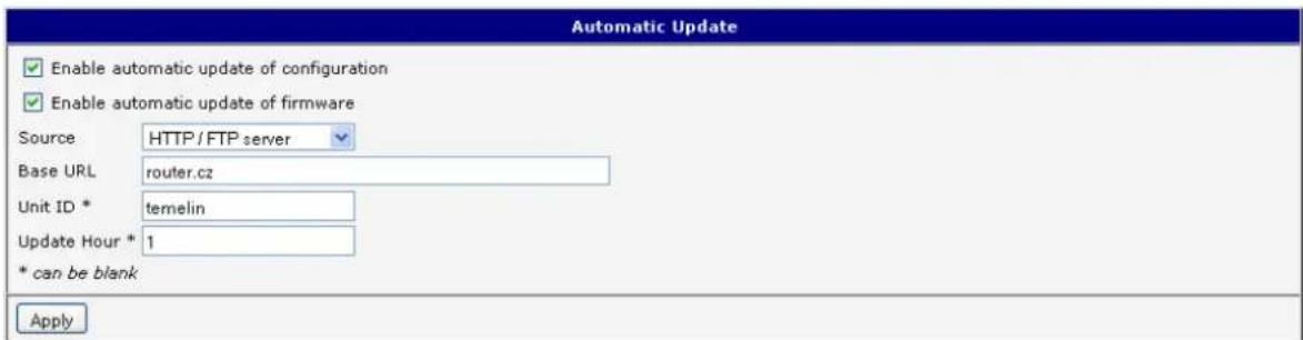
Figure 666. Example of automac update 1
The following examples check for new rmware or conguraons each day at 1:00 a.m. An example is given for the SPECTRE 3G router with MAC address 00:11:22:33:44:55.

- Firmware: hp://router.cz/spectre3g.bin
• Conguraon le: hp://router.cz/00.11.22.33.44.55.cfg
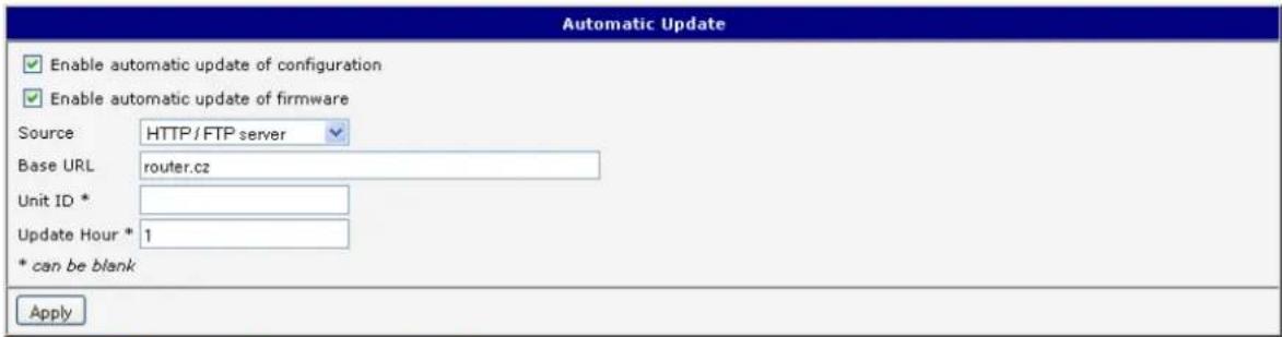
Figure 677. Example of automac update 2
USER MODULES
You may run custom soware programs in the router to enhance the features of the router. Use the User Modules menu item to add new soware modules to the router, to remove them, or to change their conguraon. Programming, compiling, and uploading user soware modules are described in the applicaon programming guide.
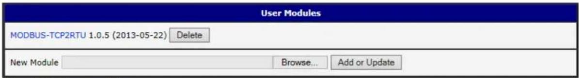
Figure 688. User modules
CHANGE PROFILE
Up to three alternate router conguraons or proles can be stored in router non-volale memory. You can save the current conguraon to a router prole through the Change Prole menu item. Select the alternate prole to store the sengs to and ensure that the Copy sengs from current prole to selected prole box is checked. The current sengs will be stored in the alternate prole aer the Apply buon is pressed. Any changes will take eect aer restarng router through the Reboot menu in the web administrator or using an SMS message.
Example of usage proles: Proles can be used to switch between dierent modes of operaon of the router such as PPP conncon, VPN tunnels, etc. It is then possible to switch between these sengs using the front panel binary input, an SMS message, or Web interface of the router.

Figure 699. Change prole
CHANGE PASSWORD
You may change the router password using the Change Password menu item. The new password will be saved aer pressing the Apply buon.
The default password is "root". It is recommended that you change the password during initial setup for higher security.

Figure 700. Change password
SET REAL TIME CLOCK
The internal clock of the router can be altered by selecng the Set Real Time Clock menu item. Date and me can be manually set by changing the Date and Time items. The clock can also be adjusted by using a NTP server. This would require you to enter the IP address or domain name of the NTP Server and click Apply to set the clock.
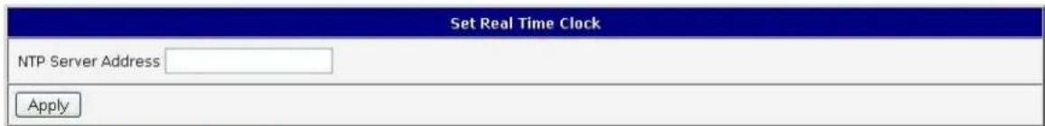
Figure 711. Set real me clock
SET SMS SERVICE CENTER ADDRESS
Note: The SPECTRE RT industrial router does not support the Set SMS service center address onpon.
The SMS service center phone number is normally programmed into the SIM card by the carrier and does not need to be manually entered. However, in some cases, it may be necessary to set the phone number of the SMS service center in order to send SMS messages. This parameter cannot be set if the SIM card already contains the SMSC informaon. The phone number can be entered with or without an internaonal prex. For example: +420 xxx xxx xxx. If you are unable to send or receive SMS messages, contact your carrier to nd out if this parameter is required. This parameter is provisioned automatically by the carrier on CDMA networks and does not need to be manually entered.

Figure 722. Set SMS service center address
UNLOCK SIM CARD
Note: The SPECTRE RT industrial router does not support the Unlock SIM card onpon.
You may lock the SIM card with a 4-8 digit PIN (Personal Idencaon Number) code to prevent unauthorized use of the SIM card. The PIN code must be entered each me that the SIM card is powered up. The SPECTRE cellular


router supports the use of a SIM card with a PIN number. Enter the PIN number into the SIM PIN eld on the conguraon page and select Apply.
Access to the SIM card is blocked if the PIN code is incorrectly entered 3 mes. Contact your SIM card provider if it has been blocked.

Figure 733. Unlock SIM card
SEND SMS
Note: The SPECTRE RT industrial router does not support the Send SMS onpon.
You can send an SMS message from the router to test the cellular network. To send an SMS message, select Send SMS from the conguraon menu. Enter the phone number and text of the message into the text boxes and click the Send buon. It may take a few seconds to send the message.

Figure 744. Send SMS
It is also possible to send an SMS message using an HTTP request in the form:
GET /send_exec.cgi?phone=%2B420712345678&message=Test HTTP/1.1
Authorizaon: Basic cm9vdDpyb290
The HTTP request will be sent to TCP conneccon on router port 80. Router sends an SMS message with text "Test". SMS is sent to phone number ""420712345678". Authorizaon is in the format "user:password" coded by BASE64. In the example is used for root:root.
You may save the current router conguraon to a le using the Backup Conguraon menu item. It is recommended that you save the current conguraon before a rmware update.
RESTORE CONFIGURATION
You may restore the router conguraon from a le using the Restore Conguraon menu item.

Figure 755. Restore conguraon
UPDATE FIRMWARE
Select the Update Firmware menu item to view the current router rmware version and load new rmware into the router. To load new rmware, browse to the new rmware le and press the Update buon to begin the update. Do not turn o the router during the rmware update.
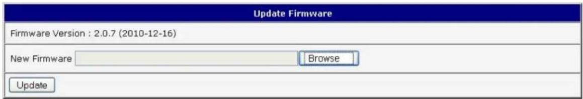
Figure 766. Update rmware
During the rmware update, the router will show the following messages:
Uploading firmware to RAM... ok
Programming FLASH...... ok
Reboot in progress
Continue here after reboot.
Aer the rmware update, the router will automacally reboot.

Note: Do not turn o the router during the rmware update.
REBOOT
The router can be rebooted remotely through the web interface. To reboot the router, select the Reboot menu item and then press the Reboot buon.
| Reboot |
| The reboot process will take about 15 seconds to complete. |
| Reboot |
Figure 777: Reboot
2. ROUTER CONFIGURATION OVER TELNET
Monitoring of status, conguraon and administraon of the router can be performed over the Telnet interface. The default IP address of the modem is 192.168.1.1. Conguraon may be performed only by the user "root" with initial password "root".
The following commands may be used to congregate the router over Telnet:
Table 70: Telnet commands
| Command | Descripon |
| cat | display le |
| cp | copy a le |
| date | show/change system me |
| df | Display informaon about le system |
| dmesg | kernel diagnosc messages |
| echo | string write |
| Email send | |
| free | Display informaon about available memory |
| gsmat | Send an AT commend |
| gsminfo | Display informaon about signal quality |
| gsmsms | SMS send |
| hwclock | display/change me in RTC |
| ifcong | display/change interface conguraon |
| io | reading/wring input/output pins |
| ip | display/change route table |
| iptables | display/change NetFilter rules |
| kill | Kill a process |
| killall | Kill all processes |
| In | link create |
| Is | dump directory contents |
| mkdir | create directory |
| mv | Move le |
| ntpdate | synchronize system me with NTP server |
| passwd | password change |
| ping | ICMP ping |
| ps | display process informaon |
| pwd | display directory contents |
| reboot | Reboot |
| rm | le delete |
| rmdir | directory delete |
| route | display/change route table |
| service | start/stop a service |
| sleep | pause number of seconds |
| slog | display system log |
| tail | display le end |
| tcpdump | monitoring of network |
| touch | le create/change me stamp |
| vi | text editor |
3. WI-FI CONFIGURATION
WI-FI ACCESS POINT
The SPECTRE 3G-W and LTE-W routers can provide wireless access to the network using a built-in 802.11bgn Wi-Fi module. Support for the Wi-Fi module is provided by a User Soware module which is pre-loaded into the SPECTRE Wi-Fi router at the factory. Only access point functionality is provided by the router.
Select the Wi-Fi user module to view the Wi-Fi AP status and conguraon. This link is located on the User Modules customizaon web page. The link to "Wi-Fi AP" informaon is in the "Status" secon.
Table 7168: Wi-Fi AP state
| Item | Descripon |
| hostapd state dump | Time stamp of actual Wi-Fi status. |
| num_sta | Number of associated staons. |
| num_sta_non_erp | Number of associated Non-ERP staons (i.e., staons using 802.11b in 802.11g BSS) |
| num_sta_no_short_slot_me | Number of associated staons, that do not support Short Slot Time |
| num_sta_no_short_preamble | Number of associated staons that do not support Short Preamble. |
Data about connected clients is displayed as well.
Table 692: Wi-Fi client state
| Item | Descripon |
| STA | MAC address of associated staon. |
| AID | STA's unique AID (1 .. 2007) or 0 if not yet assigned. |
![WiFi AP Status WiFi AP Status hostapd state dump - Thu Apr 12 11:23:58 2012 num_sta=1 num_sta_non_erp=0 num_sta_no_short_slot_time=0 num_sta_no_short_preamble=1 STA=00:b0:8c:01:0d:81 AID=1 flags=0xa23 [AUTH][ASSOC][AUTHORIZED][WMM] capability=0x401 listen_interval=3 supported_rates=82 84 8b 96 0c 12 18 24 30 48 60 6c timeout_next=NULLFUNC POLL](/content/2026/06/1187196/images/49d265b109eed2bc4f4a4351d6ffa19c13f6b09479c8f099e2ce0997377d6a5e.jpg)
Figure 788: Wi-Fi AP status
Fig. 75: Wi-Fi AP Status
WLAN DHCP
The DHCP server provides automac conguraon of devices connected to the network managed by the router. The DHCP server assigns IP address, netmask, default gateway (IP address of router) and DNS server (IP address of router) to each device.
The following table lists the informaon that is displayed in the DHCP status window for each aached client.
Table 703: Lease address
| Item | Descripon |
| lease | Assigned IP address |
| starts | Time of assignaon of IP address |
| ends | Time of terminaon IP address validity |
| hardware ethernet | Hardware MAC (unique) address |
| uid | Unique ID |
| client-hostname | Computer name |
| DHCP Status |
| Active DHCP Leases |
| lease 192.168.3.2 ( |
| starts 4 2012/04/12 11:26:21; |
| ends 4 2012/04/12 11:36:21; |
| hardware ethernet 00:b0:8c:0l:0d:8l; |
| uid 01:00:b0:8c:0l:0d:8l; |
| client-hostname "felgr2"; |
| } |
Figure 799. Wi-Fi DHCP status
WIRELESS NETWORK SCANNING
Press Scan to scan neighboring Wi-Fi networks. Scanning can only be performed if the access point (Wi-Fi AP) is OFF.
Table 714: Neighboring Wi-Fi networks
| Item | Descripon |
| BSS | MAC address of access point (AP). |
| TSF | A Timing Synchronizaon Funcon (TSF) keeps the mers for all staons in the same Basic Service Set (BSS) synchronized. All staons shall maintain a local TSF mer. |
| freq | Frequency band of access point (AP). |
| beacon interval | Period of me synchronizaon [kus] (1,024ms). |
| capability | List of access point (AP) characterisc. |
| signal | Signal level of access point (AP). |
| last seen | Last response me of access point (AP). |
| SSID | Idener for access point (AP). |
| Supported rates | Supported rates of access point (AP). |
| DS Parameter set | The channel on which broadcast access point (AP). |
WiFi Scan
List of BSSs
BSS 00:3a:98:eb:5a:30 (on wlan0)
TSF: 25078863769996 usec (290d, 06:21:03)
freq: 2467
beacon interval: 100
capability: ESS Privacy ShortPreamble ShortSlotTime (0x0431)
signal: -61.00 dBm
last seen: 230 ms ago
Information elements from Probe Response frame:
SSID: conel
Supported rates: 1.0* 2.0* 5.5* 6.0 9.0 11.0* 12.0 18.0
DS Parameter set: channel 12
ERP:
RSN: * Version: 1
* Group cipher: TKIP
* Pairwise ciphers: CCMP TKIP
* Authentication suites: PSK
* Capabilities: 4-PTKSA-RC 4-GTKSA-RC (0x0028)
Extended supported rates: 24.0 36.0 48.0 54.0
WMH: * Parameter version 1
* u-APSD
* BE: CW 15-1023, AIFSN 3
* BK: CW 15-1023, AIFSN 7
* VI: CW 7-15, AIFSN 2, TXOP 6016 usec
* V0: CW 3-7, AIFSN 2, TXOP 3264 usec
Figure 800. Wi-Fi Scan
WI-FI START LOG
If there is some problem starng Wi-Fi connecns, check the "Start Log" in the "Status" secon. It will display error reports that correspond to one or more components of the Wi-Fi AP. The basic component Wi-Fi AP (hostapd) is the exception. This component writes its log entries to the System Log.
WiFi AP Start Log
WiFi AP Start Log
Start WiFi:
If there are problems with Wi-Fi connecons you can view the system log by pressing the "System Log" menu item. You will see detailed reports from individual applicaons running in the router. Wi-Fi AP acvity is indicated in rows starng "hostapd" or "dhcpd-wi". Press the "Save" buon to save the system log to the computer.
System Log
System Messages
2012-04-12 11:40:11 System log daemon started.
2012-04-12 11:40:15 pppsd[418]: pppsd started
2012-04-12 11:40:15 pppsd[418]: turning on module
2012-04-12 11:40:15 pppsd[418]: selected SIM: primary
2012-04-12 11:40:15 dnsmasq[447]: started, version 2.59 cachesize 150
2012-04-12 11:40:15 dnsmasq[447]: cleared cache
2012-04-12 11:40:16 sshd[483]: Server listening on 0.0.0.0 port 22.
2012-04-12 11:40:20 hostapd: Configuration file: /var/wifi/hostapd.conf
2012-04-12 11:40:21 hostapd: Using interface wlan0 with hwaddr 00:22:88:02:03:6e and ssid 'Vyroba - XC WIFI'
2012-04-12 11:40:22 hostapd: wlan0: STA 00:b0:8c:01:0d:81 IEEE 802.11: authenticated
2012-04-12 11:40:22 hostapd: wlan0: STA 00:b0:8c:01:0d:81 IEEE 802.11: associated (aid 1)
2012-04-12 11:40:22 hostapd: AP-STA-CONNECTED 00:b0:8c:01:0d:81
2012-04-12 11:40:27 dhcpd-wifi[751]: DHCPREQUEST for 192.168.3.2 from 00:b0:8c:01:0d:81 via wlan0
2012-04-12 11:40:27 dhcp-wifi[751]: DHCPACK on 192.168.3.2 to 00:b0:8c:0l:0d:8l via wlan0
2012-04-12 11:40:27 dhcpd-wifi[751]: DHCPREQUEST for 192.168.3.2 from 00:b0:8c:01:0d:81 via wlan0
2012-04-12 11:40:27 dhcpd-wifi[751]: DHCPACK on 192.168.3.2 to 00:b0:8c:0l:0d:81 via wlan0
2012-04-12 11:40:28 pppsd[418]: SIM card not present or communication error
Save
Figure 822. System log
WI-FI ACCESS POINT CONFIGURATION
The conguraon page for the Wi-Fi access point is displayed by selecng Wi-Fi AP item in Conguraon secon.
Table 725: Wi-Fi AP parameters
| Item | Descripon |
| Enable Wi-Fi AP | If this item is checked, Wi-Fi AP is enabled. |
| SSID | Idener of Wi-Fi network. |
| Broadcast SSID | Method of broadcasting the SSID in beacon frames and response to a request for sending the beacon frame. Enabled - SSID is broadcast in beacon frames.Zero length - Beacon frame does not include SSID. Requests for sending beacon frame are ignored.Clear - All SSID characters in beacon frames are replaced by 0. Original length is kept. Requests for sending beacon frames are ignored. |
| Country Code | Code of the country where the router is installed. This code must be entered in ISO 3166-1 alpha-2 format. If a country code isn't specied and the router has not implemented a system to determine this code, it will use "US" as the default country code.If no country code is specied or if the wrong country code is entered, then the router may violate country-specific regulaons for the use of the Wi-Fi frequency bands. |
| HW Mode | HW mode of Wi-Fi standard that will be supported by Wi-Fi access point.IEE 802.11bIEE 802.11b+gIEE 802.11b+g+n |
| Channel | The channel, where the Wi-Fi AP is transming. |
| BW 40 MHz | The opon for HW mode 802.11n which allows transmission on two standard 20MHz channels simultaneously. |
| WMM | Basic QoS for Wi-Fi networks is enabled by checking this item. This version doesn't guarantee network throughput. It is suitable for simple applicaons that require QoS. |
| Authencaon | Access control and authorizaon of users in the Wi-Fi network.Open - Authencaon is not required. Free access point.Shared - Base authencaon using WEP key.WPA-PSK - Authencaon using beer authencaon methods PSK-PSK.WPA2-PSK - WPA-PSK using new encrypon AES. |
| Encrypon | Type of data encrypon in the Wi-Fi networkNone - No data encrypon.WEP - Encrypon using stac WEP keys. This encrypon can be used for Shared authencaon.TKIP - Dynamic encrypon key management that can be used for WPA-PSK and WPA2-PSK authencaon.AES - Improved encrypon used for WPA2-PSK authencaon. |
| WEP Key Type | Type of WEP key for WEP encrypon.ASCII - WEP key in ASCII formatHEX - WEP key in hexadecimal format |
| WEP Default Key | This item species default WEP key. |

| WEP Key X | Items for dierent 4 WEP keys.WEP key in ASCII format must be entered in quotes. This key can be specied in the following lengths.5 ASCII characters (40b WEP key)13 ASCII characters (104b WEP key)16 ASCII characters (128b WEP key)WEP key must be entered in hexadecimal digits. This key can be specied in the following lengths.10 hexadecimal digits (40b WEP key)26 hexadecimal digits (104b WEP key)32 hexadecimal digits (128b WEP key) |
| WPA PSK Type | Type of key for WPA-PSK authencaon.256-bit secretASCII passphrasePSK File |
| WPA PSK | Key for WPA-PSK authencaon. This key must be entered according to the selected WPA PSK type as follows.256-bit secret - 64 hexadecimal digitsASCII passphrase - 8 to 63 charactersPSK File - absolute path to the le containing the list of pairs (PSK key, MAC address) |
| Access List | Mode of Access/Deny list.Disabled - Accept/Deny list is not used.Accept - Clients in Accept/Deny list can access the network.Deny - Clients in Access/Deny list cannot access the network. |
| Accept/Deny List | Accept or Deny list of client MAC addresses that set network access. Each MAC address is separated by new line. |
| Syslog Level | Logging level, when system writes to the system log.Verbose debugging - The highest level of logging.DebuggingInformaonal - Default level of loggingNocaonWarning - The lowest level of communicaveness. |
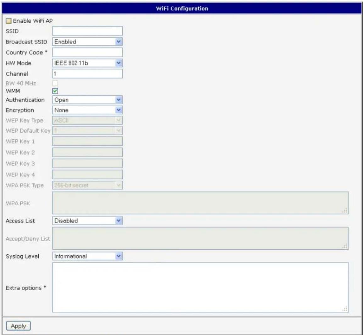
Figure 833. Wi-Fi AP conguraon page
WLAN CONFIGURATION
The Wi-Fi LAN and DHCP server page is displayed by selecng "WLAN" in the conguraon secon.
Table 73: WLAN parameter
| Item | Descripon |
| Enable WLAN interface | If this item is checked, Wi-Fi LAN is enabled. |
| IP Address | Fixed IP address of Wi-Fi network interface. |
| Subnet mask | Subnet Mask of Wi-Fi network interface. |
| Bridged | No - Bridged mode is not allowed. WLAN network is not connected with LAN router.Yes - Bridged mode is allowed. WLAN network is connected with one or more LAN network in router. In this case, the seng of most items in this table is ignored. Instead, it takes seng of selected network interface (LAN). |
| Enable dynamic DHCP leases | If this opon is checked, dynamic DHCP server is enabled. |
| IP Pool Start | Start IP addresses space. |
| IP Pool End | End IP addresses space |
| Lease Time | Time in seconds that the IP Address is available to the client |
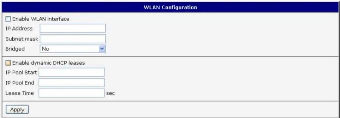
Figure 844. WLAN conguraon
WI-FI PORT LEDS
Table 747: Wi-Fi LED state indicaon
| LED port indicator | |
| Green LED | Wi-Fi port is powered on. |
| Yellow LED | Permanently o. |