
CASA - Pregnant BOWERS & WILKINS - Free user manual and instructions
Find the device manual for free CASA BOWERS & WILKINS in PDF.

| Product Type | Two-channel power supply for CASA active speakers |
| Brand | Bowers & Wilkins |
| Model | CASA Interface |
| Dimensions (H x W x D) | 90 mm x 105 mm x 305 mm (3.5 in x 4.25 in x 12 in) |
| Weight | 4 kg (9 lbs) |
| Total Output Power | 200 W @ ±24 V |
| Audio Inputs | Unbalanced, 2 V RMS, RCA phono |
| Audio Outputs | Balanced, 47 Ω source, via RJ-45 |
| Power Output per Socket | Maximum 100 W, with electronic current limit and polyswitch protection |
| Trigger Input | External, 3.5 mm jack, selectable sense (+5-12 V) |
| IR Relay Output | 3.5 mm jack, 38 kHz modulation frequency, 5 V output |
| Cable Requirement | Shielded Category 5 (STP) with RJ-45 connectors |
| Speaker Loading | 1 pair AWM70, 2 pairs AWM65, or 5 pairs ACM60 |
| DIP Switch Settings | Switch 1: Trigger sense (off = normally on, on = normally standby); Switch 2: Master/Slave (off = Master, on = Slave) |
| Ventilation | At least 50 mm (2 in) unrestricted air space on sides, 125 mm (5 in) above |
| Cleaning | Clean with dry cloth; do not use liquid cleaners |
| Safety | Do not open enclosure; no user-serviceable parts; refer servicing to qualified personnel |
| Mounting | Can be placed on shelf or mounted; ensure adequate ventilation |
| Compatibility | Designed for use with B&W CASA active speakers (AWM70, AWM65, ACM60) |
Frequently Asked Questions - CASA BOWERS & WILKINS
User questions about CASA BOWERS & WILKINS
0 question about this device. Answer the ones you know or ask your own.
Ask a new question about this device
Download the instructions for your Pregnant in PDF format for free! Find your manual CASA - BOWERS & WILKINS and take your electronic device back in hand. On this page are published all the documents necessary for the use of your device. CASA by BOWERS & WILKINS.
USER MANUAL CASA BOWERS & WILKINS
Interface Owner's manual

LISTEN AND YOU'LL SEE
CASA™ INTERFACE Owner's manual
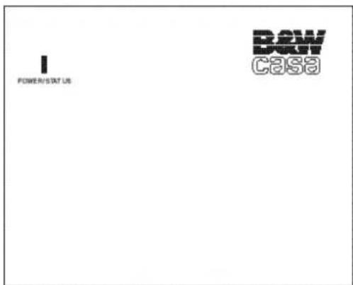
Figure 1
English 2
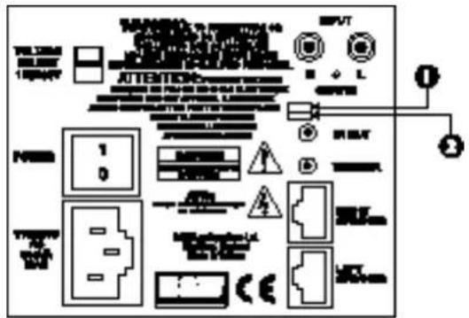
Figure 2
natural_image
Pure electrical circuit lines without any symbols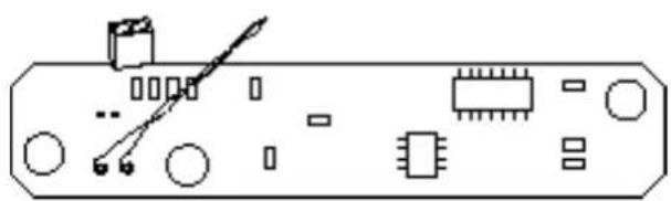
natural_image
Pure electrical circuit lines without any symbolsFigure 4
Figure 3
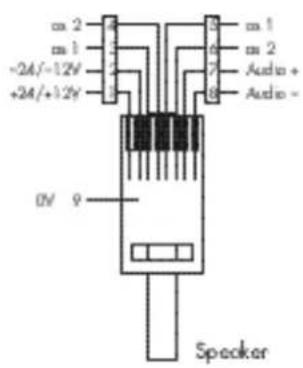
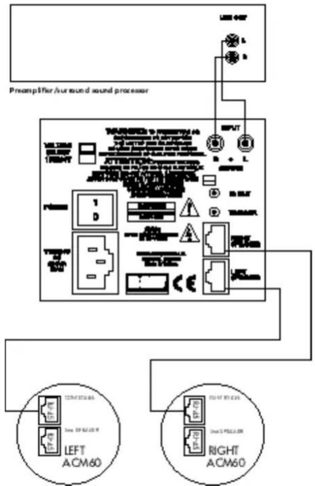
Figure 5
flowchart
graph TD
    A["VOLTAGE SELECT MΩ/MPV"] --> B["POWER 1"]
    A --> C["Power 0"]
    A --> D["DC DOWN AC MAX"]
    B --> E["T Piece SP-78"]
    C --> F["T Piece SP-79"]
    D --> G["T Piece SP-80"]
    E --> H["RIGHT AWM65 R-45"]
    F --> I["RIGHT AWM65 R-46"]
    G --> J["RIGHT AWM65 R-47"]
    H --> K["LEFT AWM65 R-48"]
    I --> L["LEFT AWM65 R-49"]
    J --> M["LEFT AWM65 R-50"]
Fig
flowchart
graph TD
    A["VA WGE SELECT 5 HV/20kV"] --> B["Pinki H"]
    B --> C["1"]
    B --> D["0"]
    E["HS-0.5kV AC 20mA MAX"] --> F["Ground"]
    G["INPUT"] --> H["COM RIO"]
    H --> I["RIGHT UNT"]
    I --> J["TRIUGER"]
    J --> K["RIGHT UNT"]
    K --> L["LEFT UNT"]
    L --> M["LEFT UNT"]
    M --> N["LEFT UNT"]
    N --> O["LEFT UNT"]
    O --> P["LEFT UNT"]
    P --> Q["LEFT UNT"]
    Q --> R["LEFT UNT"]
    R --> S["LEFT UNT"]
    S --> T["LEFT UNT"]
    T --> U["LEFT UNT"]
    U --> V["LEFT UNT"]
    V --> W["LEFT UNT"]
    W --> X["LEFT UNT"]
    X --> Y["LEFT UNT"]
    Y --> Z["LEFT UNT"]
    Z --> AA["LEFT UNT"]
    AA --> AB["LEFT UNT"]
    AB --> AC["LEFT UNT"]
    AC --> AD["LEFT UNT"]
    AD --> AE["LEFT UNT"]
    AE --> AF["LEFT UNT"]
SAFETY INSTRUCTIONS
Caution:
To reduce the risk of electric shock, do not remove the back panel. No user-serviceable parts inside. Refer servicing to qualified personnel.
Explanation of Graphical Symbols

The lightning flash within an equilateral triangle is intended to alert you to the presence of uninsulated "dangerous voltage" within the product's enclosure that may be of sufficient magnitude to constitute an electric shock to persons.

The exclamation point within an equilateral triangle is intended to alert you to the presence of important operating and maintenance (servicing) instructions in the literature accompanying the appliance
1 Read Instructions – All the safety and operating instructions should be read before the appliance is operated.
2 Retain Instructions – The safety and operating instructions should be retained for future reference.
3 Heed Warnings – All warnings on the appliance and in the operating instructions should be adhered to.
4 Follow Instructions – All operating and use instructions should be followed.
5 Water and Moisture – The appliance should not be used near water – for example, near a bathtub, washbowl, kitchen sink, laundry tub, in a wet basement, or near a swimming pool and the like.
6 Carts and Stands – The appliance should be used only with a cart or stand that is recommended by the manufacturer.
7 Wall or Ceiling Mounting – The appliance should be mounted to a wall or ceiling only as recommended by the manufacturer.
8 Ventilation – The appliance should be situated so that its location or position does not interfere with its proper ventilation. For example, the appliance should not be situated on a bed, sofa, rug, or similar surface that may block the ventilation openings; or placed in a built-in installation, such as a bookcase or cabinet, that may impede the flow of air through the ventilation openings.
9 Heat – The appliance should be situated away from heat sources such as radiators, heat registers, stoves, or other appliances that produce heat.
10 Power Sources – The appliance should be connected to a power supply only of the type described in the operating instructions or as marked on the appliance.
11 The equipment must be grounded (earthed). When using an extension power supply cord or a power supply cord other than that supplied, it should be 3-core, fitted with the appropriate moulded-on plug and carry safety approval appropriate to the country of use.
12 Power Cord Protection – Power-supply cords should be routed so that they are not likely to be walked on or pinched by items placed on or against them, paying particular attention to cords at plugs, convenience receptacles and the point where they exit from the appliance.
13 Cleaning – The appliance should be cleaned only as recommended by the manufacturer.
14 Non-use Periods – The power cord of the appliance should be unplugged from the outlet when left unused for a long period of time.
15Object and Liquid Entry – Care should be taken so that objects do not fall and liquids are not spilled into the enclosure through openings.
16 Damage Requiring Service – The appliance should be serviced by qualified personnel when:
a The power-supply cord or the plug has been damaged; or
b Objects have fallen, or liquid has been spilled into the appliance; or
c Theappliancehasbeenexposedtorain;or
d The appliance does not appear to operate normally, or exhibits a marked change in performance; or
e The appliance has been dropped, or the enclosure damaged.
17 Servicing – The user should not attempt to service the appliance beyond that described in the operating instructions. All other servicing should be referred to qualified service personnel.
Warnings:
To prevent fire or shock hazard, do not expose this equipment to rain or moisture.
Observe all warnings on the equipment itself. To avoid electrical shock, do not open the enclosure. There are no user serviceable parts inside. Refer all service questions to an authorised B&W dealer.
To prevent electric shock, do not use this (polarised) power plug with an extension cord receptacle or other outlet unless the blades can be fully inserted to prevent blade exposure.
Ensure that the voltage indicated on the rear panel matches that of the power supply.
VENTILATION – THE APPLIANCE SHOULD BE SITUATED SO THAT ITS LOCATION OR POSITION DOES NOT INTERFERE WITH ITS PROPER VENTILATION:
A.FOR THE INTERFACE: ENSURE AT LEAST 2 INCHES (50 MM) OF UNRESTRICTED AIR SPACE EITHER SIDE OF THE INTERFACE AND D5 IN CHES(125MM) OF UNRESTRICTED AIR SPACE ABOVE THE INTERFACE.
B. FOR THE SPEAKERS: ENSURE AT LEAST 2 INCHES (50 MM) OF UNRESTRICTED AIR SPACE IMMEDIATELY AROUND THE AREA OF THE REAR OF THE LOUDSPEAKER BAFFLE.
ENSURE SUFFICIENT SPACING BETWEEN CONNECTION CABLES AND SINGLE INSULATED MAINS CABLING. DO NOT RUN CONNECTION CABLES AND TELECOMMUNICATIONS OR SINGLE INSULATED MAINS CABLING IN THE SAME TRUNKING. USE CONNECTOR PLUGS AND SOCKETS WITH B&W APPROVED CASA COMPATIBLE EQUIPMENT ONLY. DO NOT USE CONNECTOR PLUGS OR SOCKETS TO CONNECT TO COMPUTER OR TELEPHONY NETWORKS OR EQUIPMENT.
INTRODUCTION
Thank you for choosing B&W.
The CASA™ Interface is designed to be used with the range of Active CASA™ speakers and offer a high quality, permanent audio installation. B&W Loudspeakers has an outstanding reputation for quality audio products. In designing its CASA™ Interface B&W set outstanding sound quality as an overriding priority. Conventional installed speaker systems use power amplifiers to drive remote passive loudspeakers. This approach often limits the size and scope of a system and its architecture. Remote powered speakers are one obvious solution. However, the industry has avoided powered speaker systems because of the need to install both power and signal cabling to each speaker. There is an additional problem involved with powered speakers in needing to switch them on and off remotely through separate control wiring. The CASA™ Interface side-steps these issues by using Active Speakers driven by remote DC power. Output lines are driven in balanced form by the Interface. This form of working permits far longer cable runs than can generally be provided in domestic audio systems without loss of quality due to cable impedance effects or interference. The connection requirement is for five signals between Active Speaker and Interface, namely two power, two signal and a ground. The adoption of Category 5 shielded RJ-45 plugs and cables means the CASA™ Interface relies on just one proven connector type and cabling, familiar from the computer and telecommunications industries. This neatly satisfies all requirements for reliability and ease of installation. The provision of DC power wiring to each Active Speaker gave the CASA™ Interface design team an easy route down which to run data from infra red (IR) receivers in the speakers back to the central Controller. This IR data is carried at high frequencies and 'piggy backs' the power supply lines, eliminating the need for separate control conductors. Third-party IR remotes send back their IR data to the central Controller through this route. CASA™ & the CASA™ Interface are the first domestic audio systems to exploit the audiophile quality of true, in-wall Active Speakers.
This manual is designed to help you install the CASA™ Interface with CASA™ speakers. If you intend to use the Interface in conjunction with the CASA™ Controller you must consult the CASA™ Installation manual packed with the CASA™ Controller. Please read this manual fully before unpacking and installing the product. It will help you to optimise its performance.
B&W maintains a network of dedicated distributors who will be able to help you should you have any problems your dealer cannot resolve.
We suggest you retain the packing for future use.
POWER & CONTROL
(Figure 1)
With the power switch on the rear of the Interface in the on position, the 3.5mm trigger socket controls the unit's power up/ standby status. This socket is configured by use of rear panel DIP switch (at the top and labelled as 1). In the off (left) position the unit is normally on and a +ve voltage of 5 -12v on the centre pin of this socket will put the unit into standby. Conversely with this switch in the on (right) position the unit is normally in standby and a +ve voltage of 5 -12v on the centre pin of this socket will switch the unit on.
The second lower DIP switch (labelled as 2) should be off (left) for the unit to be used without the CASA™ Controller. In this (Master) mode, audio from the RCA type phono inputs is present at the RJ-45 outputs. Conversely with the switch on (right) audio from these sockets is not present at the RJ-45 outputs. This (Slave) mode is required for connection of the Interface to a CASA™ Controller.
The unit is shipped with both switches off (left) and the unit set as Master and Normally on.
LOUDSPEAKERS
AWM™70
The AWM™70 is a wall-mounted 100-watt Active Speaker using a 7-inch Kevlar® bass/ midrange driver and a 1-inch aluminium dome tweeter. Two 100-watt channels of amplification are provided to power the HF and LF outputs of the active crossover. Amplifier power of this order requires substantial heatsinking which is provided both by a finned rear extrusion and the ribbed baffle itself. The crossover has a damped 2nd-order network for the bass/ midrange unit and a 3rd-order slope for the tweeter. Active equalisation is used to enhance bass output and to perform drive unit correction and phase compensation giving smooth drive unit integration and good off-axis frequency response. The crossover also features overload and DC offset protection together with a power-on mute sequence (not using relays) that ensures power-up is free from clicks and thumps. An IR receiver/ modulator is mounted in the bottom centre of the baffle. This receives IR codes from remote control handsets and transmits those codes back to the Interface by way of the power supply. An LED telltale flashes to show when an IR command has been received.
AWM™65
The AWM™65 is a wall-mounted 50-watt Active Speaker using a 6.5-inch Kevlar® bass/ midrange driver and a 1-inch aluminium dome tweeter. A high-quality passive crossover is used to integrate the mid/ bass driver and tweeter. An IR receiver/ modulator is mounted in the bottom centre of the baffle. This receives IR codes from remote control handsets and transmits those codes back to the Interface by way of the power supply. An LED telltale flashes to show when an IR command has been received.
ACM™60
The ACM ^™ 60 is a 20-watt, Active ceiling-mounted speaker using a 165 mm bass/ midrange driver with a 25 mm co-axially placed tweeter. No IR input is provided. Two RJ-45 connectors (Controller and 2nd Speaker) are provided which can be used to 'daisy chain' up to five pairs of ACM ^™ 60s. See section Loading Considerations for further details.
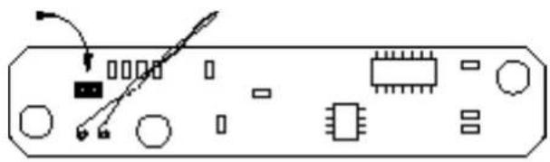
DISABLING IR
RECEIVER/ MODULATOR
(AWM™70/65 only)
(Figure 2)
If IR reception is a problem in a particular location it may be necessary to disable IR reception on a speaker. Locate the IR board behind the IR lens at the bottom of the rear of the baffle. To disable the IR receiver locate the jumper shown in the diagram below and remove it taking care not to damage any components.
CABLING
The CASA™ System and Interface are designed to use shielded Category 5 cable with R-45 connectors (24 or 26 AWG with certain loading/ distance considerations – 120 foot runs for the AWM™70 for instance). Twisted-pair cables comprise copper cores surrounded by an insulator twisted together to form a pair. The cable is a bundle of twisted pairs surrounded by an insulator. Unshielded twisted pair cable (UTP) is common in telephony applications but is unsuitable for use in CASA™ installations. Shielded twisted pair cable also (STP) offers better cross-talk and interference performance. The EIA/ TIA 568 Commercial Building Wiring Standard defines five categories of network cabling. CASA™ is designed for shielded Category 5 cable which is 100-ohm, four-wire twisted-pair cable (eight cores) certified to 100 Mbps (Mega bits per second) transmission rates in network installations. The cable has low capacitance and low cross-talk characteristics. Of the eight cores available six (three pairs) are dedicated to providing a low impedance supply to the speakers. The remaining two cores carry the audio signal. The high frequency IR data is 'piggy backed' on the DC power supply lines. The screen of the shielded cable makes a ninth connection. All cables and terminations must conform to specifications to eliminate cross-talk and interference problems. Old style connectors and jacks are not suitable. Additionally, twists in the cable pairs must be maintained up to the connection point. One other cable characteristic needs to be considered which relates to where the cable is installed. To comply with the National Electrical Code (NEC), all cable installed into the ceiling void (plenum space) must be in metal conduit or must meet local fire codes. Two types of insulation are used:
PVC (polyvinyl chloride) insulation for normal use and fluoropolymer (Teflon) insulation for plenumrated cable. We recommend the latter for CASA™ in-wall and ceiling installations. There are no twists in the cables which are wired straight through. The only criterion is that the pairs are adjacent, for example: Brown is alongside Brown/ White; Blue is alongside Blue/ White and Green is alongside Green/ White, etc.
RJ-45 CONNECTOR PIN ASSIGNMENT
(Figure 3)
The pin assignment for the RJ-45 connector (Speaker connections):
Pin Signal Comment
| 1 | +24/ +12V | 12V in Standby mode |
| 2 | -24/ -12V | 12V in Standby mode |
| 3 | as 1 | |
| 4 | as 2 | |
| 5 | as 1 | |
| 6 | as 2 | |
| 7 | + Audio | |
| 8 | - Audio | |
| 9 | 0V Screen |
LOADING CONSIDERATIONS
Interface loading is governed by the permitted number and type of speakers on any one interface. The loading of speakers for one Interface is as follows:
• 1 pair of AW M™70s
• 2 pairs of AWM™65s
- 5 pairs of ACM™60s
Exceeding this loading will not render an installation unsafe. The effect will be that all speakers cannot be played at maximum power output simultaneously.
CONNECTIONS
(Figure 4)
All connections should be made with the equipment switched off. Connect the audio source – such as a preamplifier or surround sound processor – to the RCA type phono sockets. Connect the RJ-45 terminated STP Category 5 speaker cables to the RJ-45 sockets.
Infrared remote signals picked up by speakers connected to the Interface are present at the mono 3.5mm jack at the rear of the Interface. This socket is designed to drive third party IR window emitters with its output of 5V. The modulation frequency of the IR output signal will be approximately 38kHz irrespective of the modulating frequency of the original remote control.
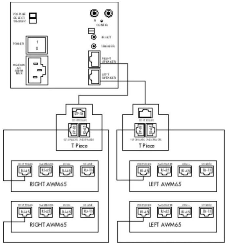
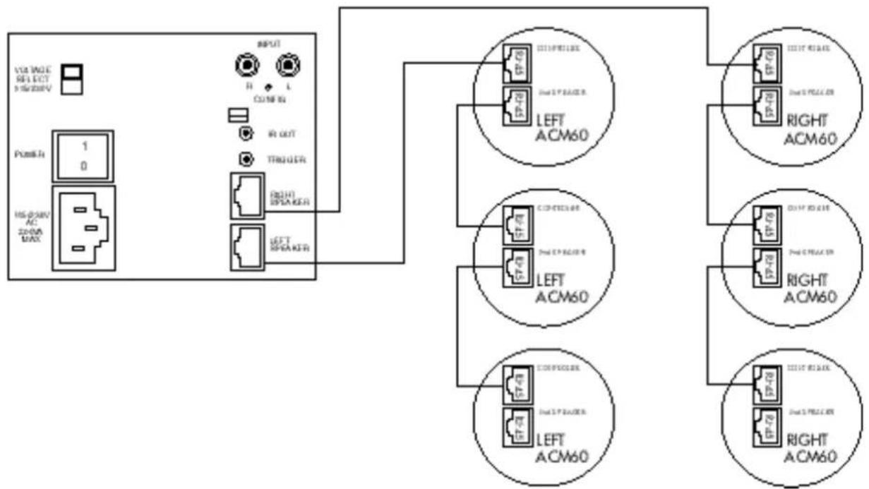
CONNECTIONS FOR ADDING SPEAKERS
Additional Speakers
(Figure 5 & 6)
Additional speakers can be connected using RJ-45 T-pieces or to the socket marked '2nd Speaker' on the ACM™60. The total loading should not be exceeded if simultaneous maximum volume levels are required – see section Loading Considerations.
CASA™ INTERFACE
Description Two channel power supply for Casa speakers
Total output power 200W @ +/ -24V
Audio inputs Unbalanced 2VRMS
Audio outputs Balanced, 47ohm source
Power outputs Maximum draw 100W per output socket, electronic current limit and polyswitch protection
Input External trigger capability, selectable sense, 3.5mm jack
Output IR relay output 38kHz modulation frequency - 3.5mm jack
Dimensions Height: 90mm (3.5in)
Width:105mm (4.25in)
Depth:305mm (12in)
Weight 4kg (9lbs)

LISTEN AND YOU'LL SEE
- CASA™ INTERFACE Owner's manual
- SAFETY INSTRUCTIONS
- Caution:
- Explanation of Graphical Symbols
- Warnings:
- INTRODUCTION
- POWER & CONTROL
- LOUDSPEAKERS
- AWM™70
- AWM™65
- ACM™60
- DISABLING IR
- RECEIVER/ MODULATOR
- (AWM™70/65 only)
- CABLING
- RJ-45 CONNECTOR PIN ASSIGNMENT
- LOADING CONSIDERATIONS
- CONNECTIONS
- CONNECTIONS FOR ADDING SPEAKERS
- Additional Speakers
- CASA™ INTERFACE
Brand : BOWERS & WILKINS
Model : CASA
Category : Pregnant