
KNC-P3BR12IR - Security Camera KT&C - Free user manual and instructions
Find the device manual for free KNC-P3BR12IR KT&C in PDF.


| Product Type | Network Security Camera (Plug-and-Play IP Camera) |
| Power Supply | 12 VDC (SELV/Limited Power Source) or 802.3af PoE |
| Environmental Protection | IP66 |
| Video Compression | H.264 (Main/High Profile), MJPEG, MPEG4 (sub-stream) |
| Audio Compression | G.711 μ-law/A-law, G.726, MP2L2 |
| Day/Night Switching | Auto (light-based), Scheduled, or Manual (Day/Night) |
| Smart IR | Yes, adjustable IR LED power based on scene brightness |
| Motion Detection | Yes, with configurable areas and sensitivity; Normal and Expert modes |
| Video Content Analysis | Line Crossing Detection, Intrusion Detection (with loitering time) |
| PTZ Control | Yes, via web interface or external pan/tilt unit; up to 128 presets |
| Network Protocols | TCP/IP, HTTP, HTTPS, RTSP, PPPoE, DDNS, SNMP, UPnP, QoS, 802.1X |
| Storage | NAS (NFS/SMB/CIFS), SD card (if supported) |
| Recording Modes | Continuous, Scheduled, Motion-Triggered, Alarm-Triggered |
| User Management | Up to 15 users (admin + 14); roles: Administrator, Operator, User |
| Web Browser Support | Internet Explorer 6+, Safari 5.02+, Firefox 3.5+, Chrome 8+ |
| Operating System (Client) | Windows XP SP1+, Vista, 7, Server 2003/2008 (32-bit) |
| Cleaning Instructions | Use clean cloth with a bit of ethanol; avoid touching lenses |
| Safety Compliance | FCC Part 15, CE (LVD, EMC, RoHS), WEEE |
Frequently Asked Questions - KNC-P3BR12IR KT&C
User questions about KNC-P3BR12IR KT&C
0 question about this device. Answer the ones you know or ask your own.
Ask a new question about this device
Download the instructions for your Security Camera in PDF format for free! Find your manual KNC-P3BR12IR - KT&C and take your electronic device back in hand. On this page are published all the documents necessary for the use of your device. KNC-P3BR12IR by KT&C.
USER MANUAL KNC-P3BR12IR KT&C
Scalable IP Solutions

natural_image
Collection of six different security cameras with visible lens and camera modules (no text or labels)Plug-and-Play Network Cameras
KNC-p3 Series
User Manual
Thank you for selecting this KT&C Omni IP Series product. For additional information please refer to the complete User Guide for this cameras series. End users should contact their KT&C Certified Dealer for service. Certified Dealers can obtain support directly from KT&C.
About This Guide
While KT&C makes every effort to insure the completeness and accuracy of the information contained in this Guide, we are not responsible for typographical errors or misprints. At the same time, KT&C reserves the right to make changes to improve the performance of our products at any time without notice, and so the specifications and content of this document are subject to change without notice. Every effort will be made to include updates in new versions of this manual and/or online.
DISCLAIMER STATEMENT
“Underwriters Laboratories Inc. (“UL”) has not tested the performance or reliability of the security or signaling aspects of this product. UL has only tested for fire, shock or casualty hazards as outlined in UL’s Standard(s) for Safety, UL60950-1. UL Certification does not cover the performance or reliability of the security or signaling aspects of this product. UL MAKES NO REPRESENTATIONS, WARRANTIES OR CERTIFICATIONS WHATSOEVER REGARDING THE PERFORMANCE OR RELIABILITY OF ANY SECURITY OR SIGNALING RELATED FUNCTIONS OF THIS PRODUCT.”
Regulatory Information
FCC Information
FCC compliance: This equipment has been tested and found to comply with the limits for a digital device, pursuant to part 15 of the FCC Rules. These limits are designed to provide reasonable protection against harmful interference when the equipment is operated in a commercial environment. This equipment generates, uses, and can radiate radio frequency energy and, if not installed and used in accordance with the instruction manual, may cause harmful interference to radio communications. Operation of this equipment in a residential area is likely to cause harmful interference in which case the user will be required to correct the interference at his own expense.
FCC Conditions
This device complies with part 15 of the FCC Rules. Operation is subject to the following two conditions:
- This device may not cause harmful interference.
- This device must accept any interference received, including interference that may cause undesired operation.
EU Conformity Statement

This product and - if applicable - the supplied accessories too are marked with "CE" and comply therefore with the applicable harmonized European standards listed under the Low Voltage Directive 2006/95/EC, the EMC Directive 2004/108/EC, the RoHS
Directive 2011/65/EU.

2012/19/EU (WEEE directive): Products marked with this symbol cannot be disposed of as unsorted municipal waste in the European Union. For proper recycling, return this product to your local supplier upon the purchase of equivalent new equipment, or dispose of it at designated collection points. For more information see: www.recyclethis.info.

2006/66/EC (battery directive): This product contains a battery that cannot be disposed of as unsorted municipal waste in the European Union. See the product documentation for specific battery information. The battery is marked with this symbol, which may include lettering to indicate cadmium (Cd), lead (Pb), or mercury (Hg). For proper recycling, return the battery to your supplier or to a designated collection point. For more information see:
www.recyclethis.info.
Safety Instructions
These instructions are intended to ensure that the camera is installed in a manner that avoids danger to persons or property loss.
These precautionary measures are divided into “Warnings” and “Cautions”
Warnings: Serious injury or death may occur if any of the warnings are neglected.
Cautions: Injury or equipment/property damage may occur if any of the cautions are neglected.
 |  |
| Warnings Follow these safeguards to prevent serious injury or death. | Cautions Follow these precautions to prevent potential injury or material damage. |

Warnings:
- In the use of the product, you must be in strict compliance with the electrical safety regulations of the nation and region. Please refer to technical specifications for detailed information.
- Input voltage should meet the requirements for both the SELV (Safety Extra Low Voltage) and Limited Power Source for 12 VDC according to the IEC60950-1 standard; or 802.3af PoE. Please refer to technical specifications for detailed information.
- If connecting several devices to one power supply, to avoid any overload that may cause over-heating or a fire hazard insure that the power supply is adequate for the power load.
- Please make sure that all plugs are firmly connected to the power sockets. When the product is mounted on wall or ceiling, the device shall be firmly attached, taking into consideration any wind, snow loading, or other factors. The mounting surface shall be capable of supporting several times the base weight of the camera.
- If smoke, unusual odors or noise come from the device, turn off the power at once and unplug the power cable, and then contact authorized service personnel.
- If the product does not work properly, please contact your dealer or the nearest service center. Never attempt to disassemble the camera yourself. (We shall not assume any responsibility for problems caused by unauthorized repair or maintenance.)
- To reduce the risk of fire or electrical shock, do not expose this product to rain or
moisture beyond the IP66 rating of applicable products.
- Installation should be performed only by qualified service personnel and should conform to all local codes.
- Please install appropriate overload protection in the power supply circuits for any necessary power supply interruption.
- Please make sure that the wall/ceiling can support more than three times the weight of the camera (and any other forces such as wind or snow loading) if the camera is mounted to a wall/ceiling.

Cautions:
- Make sure the power supply/PoE voltage is correct before using the camera.
- Do not drop the camera or subject it to physical shock.
- Do not touch lenses or sensor modules with fingers. If cleaning is necessary, use clean cloth with a bit of ethanol and wipe gently. If the camera will not be used for an extended period, please protect the lens openings from damage and/or debris.
- Avoid aiming the camera at the sun or extremely bright light sources. Blooming or smearing may occur in excessive light (which is not a malfunction), and could compromise the performance of the sensor.
- The sensor may be damaged if exposed to laser energy, so when any laser equipment is in use, make sure that the sensor will not be exposed to the laser beam.
- Do not place the camera in extremely hot or cold (see camera specifications) locations. Do not exceed the rated environmental (IP66) conditions. Do not expose the camera to high levels of electromagnetic (RF) radiation.
- To avoid heat accumulation, good ventilation is required in the operating environment.
- Keep the camera away from solvents while in use; exposure to liquids should not exceed IP66 environmental conditions.
- During shipping, the camera shall be packed in its original packing, or packing providing the equivalent protection.
- Improper use or replacement of any batteries (if so equipped) may result in the hazard of explosion. Replace with the same or equivalent type only. Dispose of used batteries according to the instructions provided by the battery manufacturer.
- If the product does not function properly, Dealers please contact KT&C; End Users please contact your KT&C Certified Dealer or an authorized service center. Do not disassemble the camera for repair or maintenance by yourself. (KT&C shall not assume any responsibility for problems caused by unauthorized repair or maintenance.)
Table of Contents
Chapter 1 System Requirements ....7
Chapter 2 Network Connection....8
2.1 Setting the Network Camera over the LAN....8
2.1.1 Wiring over the LAN....8
2.1.2 Detecting and Changing the IP Address 9
2.2 Accessing a Network Camera over a WAN.... 10
2.2.1 Static IP Connection .... 10
2.2.2 Dynamic IP Connection....11
Chapter 3 Web Access to the Network Camera ....14
3.1 Web Browser Access 14
3.2 Accessing by OMNI CMS Software 15
3.2.1 Accessing by CMS 15
3.2.2 Accessing by OMNI Remote Software 17
Chapter 4 Web Live View....18
4.1 Live View Page 18
4.2 Starting Live View.... 19
4.3 Recording and Capturing Pictures Manually 20
4.4 Operating PTZ Control.... 20
4.4.1 PTZ Control Panel 20
4.4.2 Setting / Calling a Preset....21
Chapter 5 Network Camera Configuration....23
5.1 Configuring Local Parameters.... 23
5.2 Configuring Time Settings 25
5.3 Configuring Network Settings 27
5.3.1 Configuring TCP/IP Settings 27
5.3.2 Configuring Port Settings 28
5.3.3 Configuring PPPoE Settings....29
5.3.4 Configuring DDNS Settings 29
5.3.5 Configuring SNMP Settings 33
5.3.6 Configuring 802.1X Settings....34
5.3.7 Configuring QoS Settings....35
5.3.8 Configuring UPnPTM Settings....36
5.3.9 Email Sending Triggered by Alarm 37
5.3.10 Configuring NAT (Network Address Translation) Settings 39
5.3.11 Configuring FTP Settings 39
5.4 Configuring Video and Audio Settings.... 41
5.4.1 Configuring Video Settings 41
5.4.2 Configuring Audio Settings 43
5.4.3 Configuring ROI Encoding....43
5.5 Configuring Image Parameters 45
5.5.1 Configuring Display Settings 45
5.5.2 Configuring OSD Settings....49
5.5.3 Configuring Text Overlay Settings 51
5.5.4 Configuring Privacy Mask....51
5.6 Configuring and Handling Alarms.... 52
5.6.1 Configuring Motion Detection....53
5.6.2 Configuring Video Tampering Alarm 59
5.6.3 Configuring Alarm Input 60
5.6.4 Configuring Alarm Output....61
5.6.5 Handling Exceptions....62
5.6.6 Configuring Line Crossing Detection....63
5.6.7 Configuring Intrusion Detection....64
Chapter 6 Storage Settings....68
6.1 Configuring NAS Settings 68
6.2 Configuring Recording Schedule....70
6.3 Configuring Snapshot Settings 74
Chapter 7 Playback....77
Chapter 8 Log Searching....79
Chapter 9 Other Settings....80
9.1 Managing User Accounts....80
9.2 Configuring RTSP Authentication....82
9.3 Anonymous Visit 82
9.4 IP Address Filter.... 83
9.5 Viewing Device Information.... 85
9.6 Maintenance 86
9.6.1 Rebooting the Camera 86
9.6.2 Restoring Default Settings....86
9.6.3 Exporting / Importing Configuration File....87
9.6.4 Upgrading the System....88
9.7 RS-232 Settings.... 88
Appendix 90
Appendix 1 SADP Software Introduction....90
Appendix 2 Port Mapping....93
Chapter 1 System Requirements
Operating System: Microsoft Windows XP SP1 and above version / Vista / Win7 /
Server 2003 / Server 2008 32bits
CPU: Intel Pentium IV 3.0 GHz or higher
RAM: 1G or higher
Display: 1024×768 resolution or higher
Web Browser: Internet Explorer 6.0 and above version, Safari 5.02 and above version, Mozilla Firefox 3.5 and above version and Google Chrome 8 and above versions.
Chapter 2 Network Connection
Before you start:
- If you want to set the network camera via a LAN (Local Area Network), please refer to Section 2.1 Setting the Network Camera over the LAN.
- If you want to set the network camera via a WAN (Wide Area Network), please refer to Section 2.2 Setting the Network Camera over the WAN.
- If you will use the IPC in Plug-and-Play mode, the IP configuration should be controlled by/be compatible with the NVR camera network settings. See the NVR documentation for more information.
2.1 Setting the Network Camera over the LAN
Purpose:
To view and configure the camera via a LAN, you need to connect the network camera in the same subnet with your computer, and install the OMNI Finder or OMNI CMS software to search and change the IP of the network camera.
Note: For a detailed description of OMNI Finder, please refer to Appendix 1.
2.1.1 Wiring over the LAN
The following figures show the two ways to connect a network camera to a computer. Camera power may be supplied from an external 12VDC supply, PoE switch or PoE switch or injector (not shown in these network diagrams).
Purpose:
- To test the network camera, you can connect the network camera directly to a computer with a network cable as shown in Figure 2-1 (external 12VDC power or PoE injector required).
- Refer to the Figure 2-2 to connect the network camera over a LAN via a switch or a router. When using a router during initial connection, the IPC and PC should be on the same LAN segment (on the ‘switch side’ of the router).

flowchart
graph LR
    A["Camera"] -->|or| B["Monitor"]
    B -->|Network cable| C["Computer"]
Figure 2-1 Direct Connection

flowchart
graph LR
    A["Camera"] -->|or| B["Monitor"]
    B -->|Network cable| C["Computer"]
    C -->|Network cable| D["Central Display"]
Figure 2-2 Connecting via a Switch or a Router
2.1.2 Detecting and Changing the IP Address
You need to know the camera's IP address to access the network camera.
Steps:
- To get the IP address, you can choose either of the following methods:
Use OMNI Finder, a software tool which can automatically detect active network cameras on a LAN and list the device information including IP address, subnet mask, port number, device serial number, device version, etc., shown in Figure 2-3; the IP address settings can also be set/changed using OMNI Finder.
Use the OMNI CMS software to list/change settings for the detected devices. Please refer to the user manual for OMNI CMS software for detailed information.
-
Change the IP address and subnet mask to the same subnet as that of your computer, or change your computer to match the address/subnet of the camera.
-
Enter the IP address of network camera in the address field of the web browser to view the live video.
Notes:
- The default configuration is a static IP address of 192.0.0.64; the web port number is 80; RTSP defaults to port 554, and the ‘control’ port used by OMNI CMS, OMNI Finder and other functions is
- The default user name is admin, and password is 12345.
- For accessing the network camera from different subnets, please set the gateway for the network camera, either after you logged in or though the “modify Network Parameters” applet. For more detailed information, please refer to Section 6.3.1 Configuring TCP/IP Settings.

Figure 2-3 OMNI Finder Interface
2.2 Accessing a Network Camera over a WAN
Purpose:
This section explains how to connect a network camera to a WAN with a static WAN IP or a dynamic WAN IP.
2.2.1 Static IP Connection
Before you start:
Please find out the static IP from your ISP (Internet Service Provider). With a static IP address, you can connect the network camera via a router (with that static IP address set on the WAN side of the router) or you can set WAN static IP in the camera and connect the camera directly to the WAN.
- Connecting the network camera to a WAN via a router
Steps:
- Connect the network camera to LAN side of the router.
- Assign a LAN IP address, the subnet mask and the gateway, consistent with the router LAN settings. The gateway address is the LAN IP address of the router. Refer to Section 2.1.2 Detecting and Changing the IP Address for discussion of detailed IP address configuration of the camera.
- Program the static IP (entire configuration: IP, subnet, gateway and DNS settings) into the WAN settings for the router.
- Set port mapping (or forwarding), for the camera ports (e.g., 80, 8000, and 554), so that you may access these camera ports through the router. The steps for port mapping vary according to the different routers. Please call the router manufacturer for assistance with port mapping.
Note: Refer to Appendix 2 for detailed information about port mapping.
- Connect to the network camera over the internet using a web browser or the OMNI CMS client software.

flowchart
graph LR
    A["Camera or Network Camera"] -->|Network cable| B["Router with Static IP"]
    B -->|Network cable| C["Internet"]
    C -->|Network cable| D["Computer"]
Figure 2-4 Accessing the Camera through Router with Static IP
- Connecting the network camera directly to the Internet using a static IP
You can also save the static IP in the camera and connect it directly to the Internet without using a router.
Refer to Section 2.1.2 Detecting and Changing the IP Address for detailed IP address configuration of the camera.

flowchart
graph LR
    A["Camera"] -->|or| B["Static IP"]
    B -->|-Network cable-| C["Internet"]
    C -->|-Network cable-| D["Computer"]
Figure 2-5 Accessing the Camera with Static IP Directly
2.2.2 Dynamic IP Connection
Before you start:
Please obtain a dynamic IP from an ISP. With a dynamic IP address, you can access the network camera
through a modem or a router.
- Connecting the network camera via a router
Steps:
- Connect the network camera to the router.
- In the camera, assign a static LAN IP address, the subnet mask and the gateway. Setting a DNS server address is highly recommended (and required to be able to use DDNS). Refer to Section 2.1.2 Detecting and Changing the IP Address for detailed LAN configuration.
- Confirm that the router is connected to the ISP and has received a WAN IP address.
- Set port mapping. E.g. for ports 80, 8000, and 554 ports. The steps for port mapping vary depending on different routers. Please call the router manufacturer for assistance with port mapping.
Note: Refer to Appendix 2 for detailed information about port mapping.
-
Create a DDNS name from a DDNS provider. It may be necessary to create an account with the provider. Using a DDNS name, you can reliably and consistently connect to a device (camera or DVR or NVR) even if the dynamic WAN IP address issued by the ISP changes.
-
Configure the DDNS settings in the setting interface of the router or camera.
-
Access the camera via the DDNS name (and port, if needed).
- Connecting the network camera via a DSL modem connection requiring login authentication
Purpose:
This camera supports the PPPoE function. The camera gets a public IP address from a DSL connection after the camera is connected to a DSL modem and authenticated on the network. You need to configure the PPPoE parameters in the network camera. Refer to Section 5.3.3 Configuring PPPoE Settings for detailed configuration.

flowchart
graph LR
    A["or"] --> B["Network Camera"]
    B --> C["Modem"]
    C --> D["Internet"]
    D --> E["Computer"]
    style A fill:#f9f,stroke:#333
    style B fill:#ccf,stroke:#333
    style C fill:#cfc,stroke:#333
    style D fill:#fcc,stroke:#333
    style E fill:#cff,stroke:#333
Figure 2-6 Accessing the Camera with DSL/Dynamic IP
Note: The IP address is dynamically assigned via PPPoE, so the IP address often changes after rebooting the camera. To solve the inconvenience of having a dynamic IP, use a DDNS domain name from a DDNS
provider (e.g. SimpleDDNS.com). Please follow the steps below for normal domain name resolution and private domain name resolution to address the DHCP problem.
♦ Normal Domain Name Resolution

flowchart
graph LR
    A["or Network Camera"] -->|Network cable| B["Port Map"]
    B -->|Network cable| C["Internet"]
    C -->|Network cable| D["Computer"]
    E["Domain Name Resolution Server"] --> B
Figure 2-7 Normal Domain Name Resolution
Steps:
- Obtain a DDNS name from a DDNS service provider.
- Configure the DDNS settings in the DDNS Settings interface of the network camera. Refer to Section 6.3.4 Configuring DDNS Settings for detailed configuration.
- Access the camera via the pre-defined domain name.
◆ Private Domain Name Resolution

flowchart
graph LR
    A["or"] -->|Network cable| B["Port Map"]
    C["Network Camera"] -->|Network cable| B
    B -->|Network cable| D["Internet"]
    E["PC+IP Server+ Static IP"] -->|Network cable| D
    D -->|Network cable| F["Computer"]
Figure 2-8 Private Domain Name Resolution
Steps:
- Install and run IP Server software in a computer with a static IP.
- Access the network camera through the LAN with a web browser or the client software.
- Enable DDNS and select IP Server as the protocol type. Refer to Section 6.3.4 Configuring DDNS Settings for detailed configuration.
Chapter 3 Web Access to the Network Camera
System Requirements:
Operating System: Microsoft Windows XP SP1 and above version / Vista / Win7 /
Server 2003 / Server 2008 32bits
CPU: Intel Pentium IV 3.0 GHz or higher
RAM: 1G or higher
Display: 1024×768 resolution or higher
Web Browser: Internet Explorer 6.0 and above version, Apple Safari 5.02 and above version, Mozilla Firefox 3.5 and above version and Google Chrome8 and above version
Steps:
- Open the web browser.
- In the browser address bar, input the IP address of the network camera, e.g., 192.0.0.64 and press the Enter key to display the login interface.
- Input the user name and password.
- Click Login.

Figure 3-1 Login Interface
- Install the plug-in before viewing the live video and managing the camera. Please follow the installation prompts to install the plug-in.

It is recommended to close the web browser before finishing the installation of the plug-in.
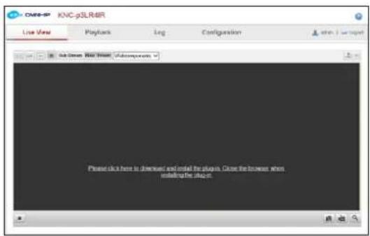
Figure 3-2 Download Plug-in

Figure 3-3 Install Plug-in (1)
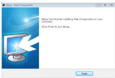
Figure 3-4 Install Plug-in (2)
- Reopen the web browser after the installation of the plug-in and repeat steps 2-4 to login.

3.2 Accessing by OMNI CMS Software
3.2.1 Accessing by CMS
The product CD contains OMNI CMS. You can view the live video and manage the camera with the software.
Follow the installation prompts to install the software. The control panel and live view interface of CMS are shown as below.
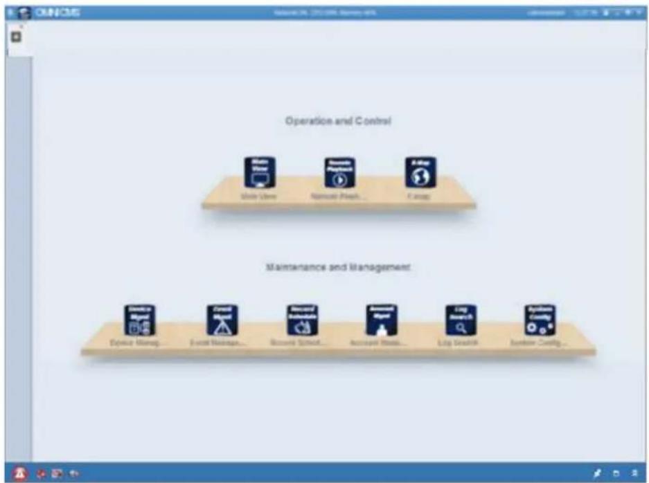
Figure 3-5 CMS Control Panel
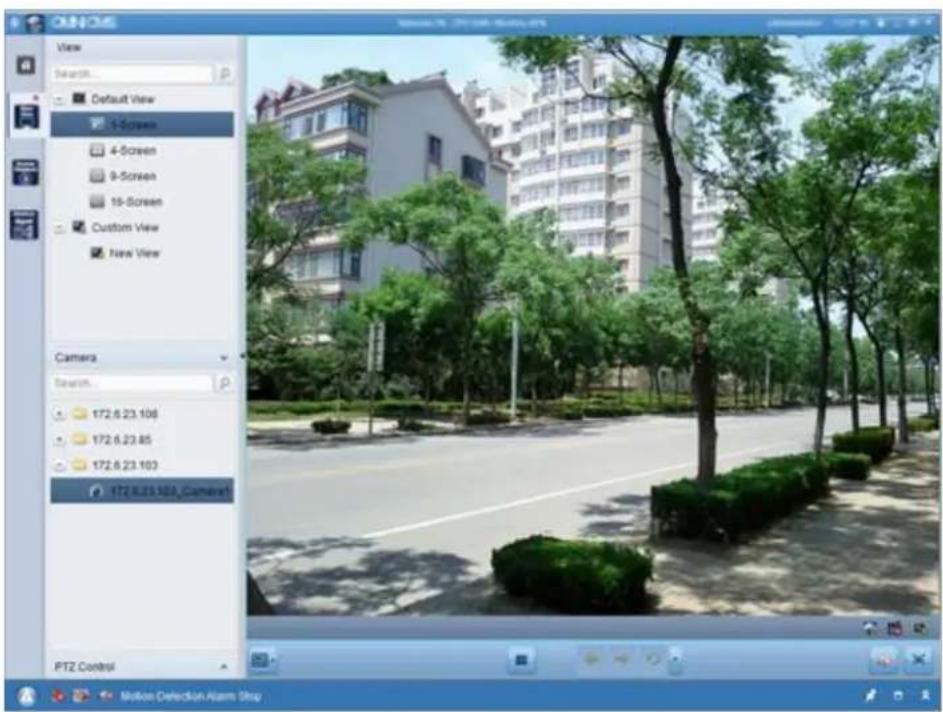
Figure 3-6 CMS Live View Interface
Note: For detailed information about the software, please refer to the user manual for
OMNI CMS.
3.2.2 Accessing by OMNI Remote Software
To view the camera with a mobile phone, you can just install the OMNI Remote software in your iOS or Android mobile phone. The software can be found in the App Store and Google Play.
Note: For detailed information about OMNI Remote software, please refer to the user manual for OMNI Remote.
Chapter 4 Web Live View
4.1 Live View Page
Purpose:
The live view page allows you to view the real-time video, capture images, realize PTZ control, set/call presets and configure video parameters.
Log in the network camera to enter the live view page, or you can click Live View on the menu bar of the main page to enter the live view page.
Sections of the live view tab page:

Figure 4-1 Live View Page
Menu Bar:
Click each tab to enter Live View, Playback, Log and Configuration page respectively.
Display Control:
Click each tab to adjust the layout and the stream type of the live view. And you can click the drop-down to select the plug-in. When using IE (internet explorer), webcomponents and quick time are selectable; for other browsers, webcomponents, quick time, VLC or MJPEG is selectable if they are supported by the web browser.
Live View Window:
Display the live video.
Toolbar:
Operations on the live view page, e.g., live view, capture, record, audio on/off, two-way audio, etc.
PTZ Control:
Panning, tilting and zooming actions of the camera and the lighter and wiper control (if it supports PTZ function or an external pan/tilt unit has been installed).
Preset Setting/Calling:
Set and call the preset for the camera (if supports PTZ function or an external pan/tilt unit has been installed).
4.2 Starting Live View
In the live view tab as shown in Figure 5-2, click ▶ on the toolbar to start the live view of the camera.

Figure 4-2 Live View Toolbar
Table 4-1 Descriptions of the Toolbar
| Icon | Description |
 | Start/Stop live view. |
 | The window size is 4:3. |
 | The window size is 16:9. |
| [7YAS] | The original widow size. |
| [TSYH] | Self-adaptive window size. |
 | Live view with the main stream. |
 | Live view with the sub stream. |
 | Live view with the third stream. |
| [288Y] | Click to select the third-party plug-in. |
 | Manually capture the picture. |
 | Manually start/stop recording. |
| [S4DZ] | Audio on and adjust volume /Mute. |
| [ST52] | Turn on/off microphone. |
 | Turn on/off 3D zooming function. |
4.3 Recording and Capturing Pictures Manually
In the live view interface, click 📷 on the toolbar to capture the live pictures or click 📷 to record the live view. The saving paths of the captured pictures and clips can be set on the Configuration > Local Configuration page. To configure remote scheduled recording, please refer to Section 7.2.
Note: The captured image will be saved as JPEG file or BMP file in your computer.
4.4 Operating PTZ Control
Purpose:
In the live view interface, you can use the PTZ control buttons to exercise pan/tilt/zoom control of cameras so equipped.
Before you start:
To achieve PTZ control, the camera connected to the network must support the PTZ function or a pan/tilt unit has been installed to the camera.
4.4.1 PTZ Control Panel
On the live view page, click 📋<< to show the PTZ control panel or click 📋>> to hide it. Click the direction buttons to control the pan/tilt movements.

Figure 4-3 PTZ Control Panel
Click the zoom/iris/focus buttons to realize lens control.
Notes:
- There are 8 direction arrows ( , , , , , , , ) in the live view window when you click and drag the mouse in the relative positions.
- For the cameras which support lens movements only, the direction buttons are invalid.
Table 4-2 Descriptions of PTZ Control Panel
| Icon | Description |
 | Zoom in/out |
 | Focus near/far |
 | Iris +/- |
 | Light on/off |
 | Wiper on/off |
 | One-touch focus |
 | Initialize lens |
 | Adjust speed of pan/tilt movements |
4.4.2 Setting / Calling a Preset
- Setting a Preset:
- In the PTZ control panel, select a preset number from the preset list.
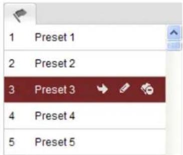
Figure 4-4 Setting a Preset
-
Use the PTZ control buttons to move the lens to the desired position.
-
Pan the camera to the right or left.
- Tilt the camera up or down.
- Zoom in or out.
-
Refocus the lens.
-
Click to finish the setting of the current preset.
-
You can click to delete the preset.
Note: You can configure up to 128 presets.
- Calling a Preset:
This feature enables the camera to point to a specified preset scene manually or when an event takes place.
For the defined preset, you can call it at any time to the desired preset scene.
In the PTZ control panel, select a defined preset from the list and click to call the preset.
Or you can place the mouse on the presets interface, and call the preset by typing the preset No. to call the corresponding presets.

Figure 4-5 Calling a Preset
Chapter 5 Network Camera Configuration
5.1 Configuring Local Parameters
Note: The local configuration refers to the parameters of the live view, record files and captured pictures. The record files and captured pictures are the ones you record and captured using the web browser and thus the file paths for these are on the PC running the browser (or other folders available to the PC).
Steps:
- Enter the Local Configuration interface:
Configuration > Local Configuration

Figure 5-1 Local Configuration Interface
- Configure the following settings:
● Live View Parameters: Set the protocol type and live view performance.
◆ Protocol Type: TCP, UDP, MULTICAST and HTTP are selectable.
TCP: Ensures complete delivery of streaming data and better video quality, yet the real-time transmission will be affected.
UDP: Provides real-time audio and video streams.
HTTP: Allows the same quality as of TCP without setting specific ports for
streaming under some network environments.
MULTICAST: It's recommended to select MCAST type when using the Multicast function. For detailed information about Multicast, refer to Section 6.3.1 TCP/IP Settings.
Live View Performance: Set the live view performance to Shortest Delay, Real Time, Balanced or Best Fluency.
Rules: It refers to the rules on your local browser, select enable or disable to display or not display the colored marks when the motion detection is triggered.
◆ Image Format: Choose the image format for picture capture.
- Record File Settings: Set the saving path of the recorded video files. Valid for the record files you recorded with the web browser.
Record File Size: Select the packed size of the manually recorded and downloaded video files to 256M, 512M or 1G. After the selection, the maximum record file size is the value you selected.
◆ Save record files to: Set the saving path for the manually recorded video files.
- Save downloaded files to: Set the saving path for the downloaded video files in playback mode.
- Picture and Clip Settings: Set the saving paths of the captured pictures and clipped video files. Valid for the pictures you captured with the web browser.
- Save snapshots in live view to: Set the saving path of the manually captured pictures in live view mode.
- Save snapshots when playback to: Set the saving path of the captured pictures in playback mode.
◆ Save clips to: Set the saving path of the clipped video files in playback mode.
Note: You can click Browse to change the directory for saving the clips and pictures.
- Click Save to save the settings.
5.2 Configuring Time Settings
Purpose:
You can follow the instructions in this section to configure the time synchronization and DST settings.
Steps:
- Enter the Time Settings interface:
Configuration > Basic Configuration > System > Time Settings
Or Configuration > Advanced Configuration > System > Time Settings
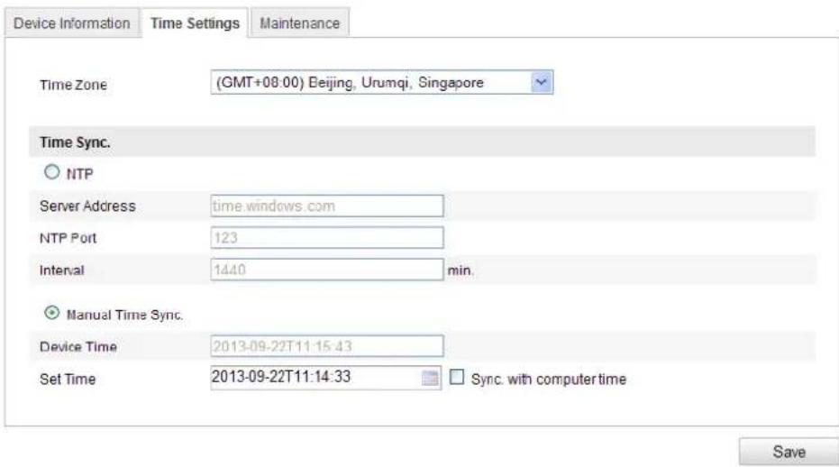
Figure 5-2 Time Settings
- Select the Time Zone.
Select the Time Zone of your location from the drop-down menu.
◆ Synchronizing Time by NTP Server.
(1) Check the checkbox to enable the NTP function.
(2) Configure the following settings:
Server Address: IP address of NTP server.
NTP Port: Port of NTP server.
Interval: The time interval between the two synchronizing actions with NTP server.

Figure 5-3 Time Sync by NTP Server
Note: If the camera is connected to a public network, you should use a NTP server that has a time synchronization function, such as the server at the National Time Center (IP Address: 210.72.145.44). If the camera is set in a customized network, NTP software can be used to establish a NTP server for time synchronization.
◆ Synchronizing Time Synchronization Manually
Enable the Manual Time Sync function and then click

to set the system time
from the pop-up calendar.
Note: You can also check the Sync with computer time checkbox to synchronize the time of the camera with that of your computer.


Figure 5-4 Time Sync Manually
- Click the DST tab page to enable the DST function and Set the date of the DST period.

Figure 5-5 DST Settings
- Click Save to save the settings.
5.3 Configuring Network Settings
5.3.1 Configuring TCP/IP Settings
Purpose:
TCP/IP settings must be properly configured before you operate the camera over network. The camera supports both the IPv4 and IPv6. Both versions may be configured simultaneously without conflicting to each other, and at least one IP version should be configured.
Steps:
- Enter TCP/IP Settings interface:
Configuration > Basic Configuration > Network > TCP/IP
Or Configuration > Advanced Configuration > Network > TCP/IP

Figure 5-6 TCP/IP Settings
- Configure the basic network settings, including the NIC Type, IPv4 or IPv6 Address, IPv4 or IPv6 Subnet Mask, IPv4 or IPv6 Default Gateway, MTU settings and Multicast Address.
Notes:
● The valid value range of MTU is 500 \~ 1500.
- The Multicast sends a stream to the multicast group address and allows multiple clients to acquire the stream at the same time by requesting a copy from the multicast group address. Before utilizing this function, you have to enable the Multicast function of your router.
- Click Save to save the above settings.
Note: A reboot is required for the settings to take effect.
5.3.2 Configuring Port Settings
Purpose:
You can set the port No. of the camera, e.g. HTTP port, RTSP port and HTTPS port.
Steps:
- Enter the Port Settings interface:
Configuration > Basic Configuration > Network > Port
Or Configuration > Advanced Configuration > Network > Port

Figure 5-7 Port Settings
- Set the HTTP port, RTSP port and HTTPS port of the camera.
HTTP Port: The default port number is 80, and it can be changed to any port No. which is not occupied.
RTSP Port: The default port number is 554 and it can be changed to any port No. ranges from 1024 to 65535.
HTTPS Port: The default port number is 443, and can be changed to any port No.
which is not occupied.
Server Port: The default server port number is 8000, and it can be changed to any port No. ranges from 2000 to 65535.
- Click Save to save the settings.
Note: A reboot is required for the settings to take effect.
5.3.3 Configuring PPPoE Settings
Steps:
- Enter the PPPoE Settings interface:
Configuration >Advanced Configuration > Network > PPPoE
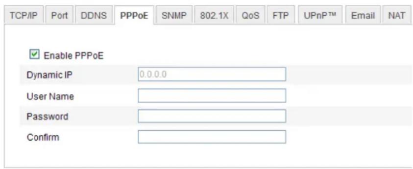
Figure 5-8 PPPoE Settings
- Check the Enable PPPoE checkbox to enable this feature.
- Enter User Name, Password, and Confirm password for PPPoE access.
Note: The User Name and Password should be assigned by your ISP.
- Click Save to save and exit the interface.
Note: A reboot is required for the settings to take effect.
5.3.4 Configuring DDNS Settings
Purpose:
If your camera is set to use PPPoE as its default network connection, you can use the Dynamic DNS (DDNS) for network access.
Before you start:
Registration on the DDNS server is required before configuring the DDNS settings of
the camera.
Steps:
- Enter the DDNS Settings interface:
Configuration > Advanced Configuration > Network > DDNS
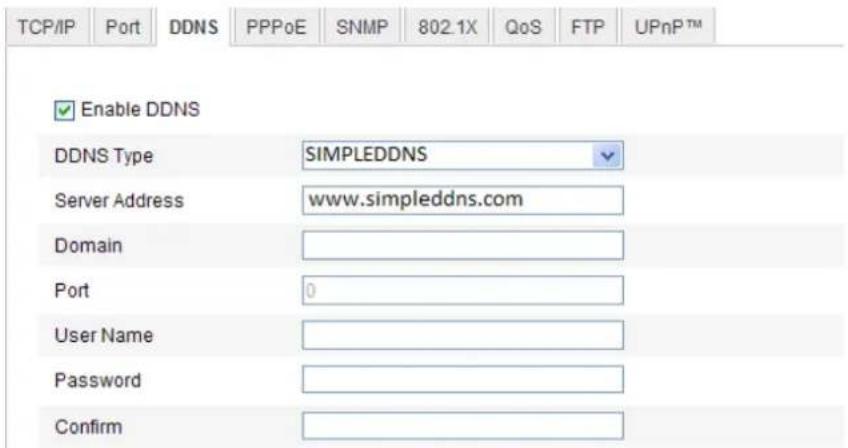
Figure 5-9 DDNS Settings
- Check the Enable DDNS checkbox to enable this feature.
- Select DDNS Type. Four DDNS types are selectable: SIMPLEDDNS, NO-IP IPServer and DynDNS.
- DynDNS:
Steps:
(1) Enter Server Address of DynDNS (e.g. members.dyndns.org).
(2)In the Domain text field, enter the domain name obtained from the DynDNS website.
(3) Enter the Port of DynDNS server.
(4)Enter the User Name and Password registered on the DynDNS website.
(5) Click Save to save the settings.
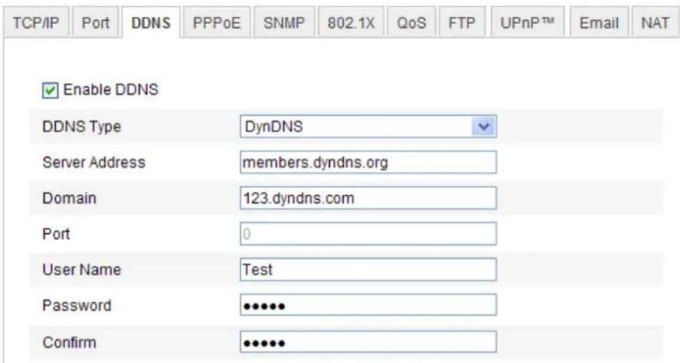
Figure 5-10 DynDNS Settings
- IP Server:
Steps:
(1) Enter the Server Address of the IP Server.
(2) Click Save to save the settings.
Note: For the IP Server, you have to apply a static IP, subnet mask, gateway and preferred DNS from the ISP. The Server Address should be entered with the static IP address of the computer that runs the IP Server software.

Figure 5-11 IPServer Settings
Note: For the US and Canada area, you can enter 173.200.91.74 as the server address.
- NO-IP:
Steps:
(1) Choose the DDNS Type as NO-IP.

Figure 5-12 NO-IP DNS Settings
(2) Enter the Server Address as www.noip.com
(3) Enter the Domain name you registered.
(4) Enter the Port number, if needed.
(5) Enter the User Name and Password.
(6) Click Save and then you can view the camera with the domain name.
- SIMPLEDDNS
Steps:
(1) Choose the DDNS Type as SIMPLEDDNS.
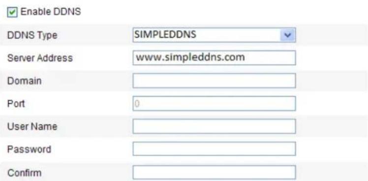
Figure 5-13 SIMPLEDDNS Settings
(2) Enter the Server Address www.simpleddns.com.
(3) Enter the Domain name (DDNS name) of the camera. The domain is the same with the device alias in the SIMPLEDDNS server.
(4) Click Save to save the new settings.
5.3.5 Configuring SNMP Settings
Purpose:
You can set the SNMP function to get camera status, parameters and alarm related information and manage the camera remotely when it is connected to the network.
Before you start:
Before setting the SNMP, please download the SNMP software and manage to receive the camera information via SNMP port. By setting the Trap Address, the camera can send the alarm event and exception messages to the surveillance center.
Note: The SNMP version you select should be the same as that of the SNMP software.
And you also need to use the different version according to the security level you required. SNMP v1 provides no security and SNMP v2 requires password for access.
And SNMP v3 provides encryption and if you use the third version, HTTPS protocol must be enabled.
Steps:
- Enter the SNMP Settings interface:
Configuration > Advanced Configuration > Network > SNMP
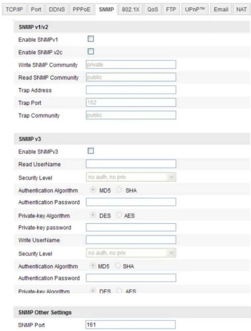
Figure 5-14 SNMP Settings
- Check the corresponding version checkbox ( ,Enable SNMP SNMPv1
Enable SNMP v2c , ) to enable the feature.
- Configure the SNMP settings.
Note: The settings of the SNMP software should be the same as the settings you configure here.
- Click Save to save and finish the settings.
Note: A reboot is required for the settings to take effect.
5.3.6 Configuring 802.1X Settings
Purpose:
The IEEE 802.1X standard is supported by the network cameras, and when the feature is enabled, the camera data is secured and user authentication is needed when connecting the camera to the network protected by the IEEE 802.1X.
Before you start:
The authentication server must be configured. Please apply and register a user name and password for 802.1X in the server.
Steps:
- Enter the 802.1X Settings interface:
Configuration > Advanced Configuration > Network > 802.1X

Figure 5-15 802.1X Settings
- Check the Enable IEEE 802.1X checkbox to enable the feature.
- Configure the 802.1X settings, including EAPOL version, user name and password.
Note: The EAPOL version must be identical with that of the router or the switch.
- Enter the user name and password to access the server.
- Click Save to finish the settings.
Note: The camera supports Wi-Fi function doesn't support 802.1X.
5.3.7 Configuring QoS Settings
Purpose:
QoS (Quality of Service) can help solve the network delay and network congestion by configuring the priority of data sending.
Steps:
- Enter the QoS Settings interface:
Configuration > Advanced Configuration > Network > QoS

Figure 5-16 QoS Settings
- Configure the QoS settings, including video / audio DSCP, event / alarm DSCP and Management DSCP.
The valid value range of the DSCP is 0-63. The bigger the DSCP value is, the higher the priority is.
Note: DSCP refers to the Differentiated Service Code Point; and the DSCP value is used in the IP header to indicate the priority of the data.
- Click Save to save the settings.
5.3.8 Configuring UPnPTM Settings
Universal Plug and Play (UPnP TM ) is a networking architecture that provides compatibility among networking equipment, software and other hardware devices.
The UPnP protocol allows devices to connect seamlessly and to simplify the implementation of networks in the home and corporate environments.
With the function enabled, you don't need to configure the port mapping for each port, and the camera is connected to the Wide Area Network via the router.
Steps:
- Enter the UPnP TM settings interface.
Configuration >Advanced Configuration >Network >UPnP
- Check the checkbox to enable the UPnPTM function.
The name of the device when detected online can be edited.

Figure 5-17 Configure UPnP Settings
5.3.9 Email Sending Triggered by Alarm
Purpose:
The system can be configured to send an Email notification to all designated receivers if an alarm event is detected, e.g., motion detection event, video loss, video tampering, etc.
Before you start:
Please configure the DNS Server settings under Basic Configuration > Network > TCP/IP or Advanced Configuration > Network > TCP/IP before using the Email function.
Steps:
- Enter the TCP/IP Settings (Configuration > Basic Configuration > Network > TCP/IP or Configuration > Advanced Configuration > Network > TCP/IP) to set the IPv4 Address, IPv4 Subnet Mask, IPv4 Default Gateway and the Preferred DNS Server. If you don't have a DNS server entry, it is unlikely that emails can be sent successfully.
Note: Please refer to Section 6.3.1 Configuring TCP/IP Settings for detailed information.
- Enter the Email Settings interface:
Configuration > Advanced Configuration > Network > Email

Figure 5-18 Email Settings
- Configure the following settings:
Sender: The name of the email sender.
Sender's Address: The email address of the sender.
SMTP Server: The SMTP Server IP address or host name (e.g.,
smtp.263xmail.com).
SMTP Port: The SMTP port. The default TCP/IP port for SMTP is 25 (not secured). And the SSL SMTP port is 465.
Enable SSL: Check the checkbox to enable SSL if it is required by the SMTP server.
Attached Image: Check the checkbox of Attached Image if you want to send emails with attached alarm images.
Interval: The interval refers to the time between two actions of sending attached pictures.
Authentication (optional): If your email server requires authentication, check
this checkbox to use authentication to log in to this server and enter the login user
Name and password.
Choose Receiver: Select the receiver to which the email is sent. Up to 2 receivers can be configured.
Receiver: The name of the user to be notified.
Receiver's Address: The email address of user to be notified.
- Click Save to save the settings.
5.3.10 Configuring NAT (Network Address Translation) Settings
Purpose:
- Enter the NAT settings interface.
Configuration >Advanced Configuration > Network > NAT
- Choose the port mapping mode.
To port mapping with the default port numbers:
To port mapping with the customized port numbers:
Choose Port Mapping Mode Manual
And for manual port mapping, you can customize the value of the port number by yourself.

Figure 5-19 Configure NAT Settings
- Click Save to save the settings.
5.3.11 Configuring FTP Settings
Purpose:
You can configure the FTP server related information to enable the uploading of the captured pictures to the FTP server. The captured pictures can be triggered by events
or a timing snapshot task.
Steps:
- Enter the FTP Settings interface:
Configuration >Advanced Configuration > Network > FTP
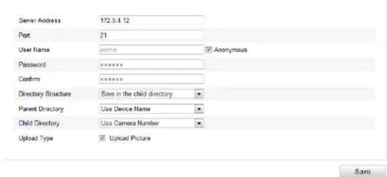
Figure 5-20 FTP Settings
- Configure the FTP settings; and the user name and password are required for login the FTP server.
Directory: In the Directory Structure field, you can select the root directory, parent directory and child directory. When the parent directory is selected, you have the option to use the Device Name, Device Number or Device IP for the name of the directory; and when the Child Directory is selected, you can use the Camera Name or Camera No. as the name of the directory.
Upload type: To enable uploading the captured picture to the FTP server.
Anonymous Access to the FTP Server (in which case the user name and password won't be required.): Check the Anonymous checkbox to enable the anonymous access to the FTP server.

Figure 5-21 FTP Settings
Note: The anonymous access function must be supported by the FTP server.
- Click Save to save the settings.
Note: If you want to upload the captured pictures to FTP server, you have to enable the continuous snapshot or event-triggered snapshot on Snapshot page.
For detailed information, please refer to the Section 6.6.7.
5.4 Configuring Video and Audio Settings
5.4.1 Configuring Video Settings
Steps:
- Enter the Video Settings interface:
Configuration >Basic Configuration >Video / Audio >Video
Or Configuration > Advanced Configuration > Video / Audio > Video

Figure 5-22 Configure Video Settings
- Select the Stream Type of the camera to main stream (normal), sub-stream or third stream.
The main stream is usually for recording and live viewing with good bandwidth, and the sub-stream and third stream can be used for live viewing when the bandwidth is limited.
- You can customize the following parameters for the selected main stream or sub-stream:
Video Type:
Select the stream type to video stream, or video & audio composite stream. The audio signal will be recorded only when the Video Type is Video & Audio.
Resolution:
Select the resolution of the video output.
Bitrate Type:
Select the bitrate type to constant or variable.
Video Quality:
When bitrate type is selected as Variable, 6 levels of video quality are selectable.
Frame Rate:
Set the frame rate to 1/16\~30 fps. The frame rate is to describe the frequency at which the video stream is updated and it is measured by frames per second (fps).
A higher frame rate is advantageous when there is movement in the video stream, as it maintains image quality throughout.
Max. Bitrate:
Set the max. bitrate to 32\~16384 Kbps. The higher value corresponds to the higher video quality, but the higher bandwidth is required.
Video Encoding:
If the Stream Type is set to main stream, H.264 and MJPEG are selectable, and if the stream type is set to sub stream, H.264, MJPEG, and MPEJ4 are selectable.
Note: The supported video encoding may differ according to the different platform.
Profile:
Basic profile, Main Profile and High Profile for coding are selectable.
I Frame Interval:
Set the I-Frame interval to 1\~400.
SVC:
Scalable Video Coding is an extension of the H.264/AVC standard. Set it OFF or
ON according to your actual needs.
- Click Save to save the settings.
5.4.2 Configuring Audio Settings
Steps:
- Enter the Audio Settings interface
Configuration > Basic Configuration > Video / Audio > Audio
Or Configuration > Advanced Configuration > Video / Audio > Audio

Figure 5-23 Audio Settings
- Configure the following settings.
Audio Encoding: G.711 ulaw, G.711 alaw, G.726, and MP2L2 are selectable. And 32kbps, 64kbps, and 128kbps are supported if MP2L2 is selected.
Audio Input: MicIn and Linein are selectable for the connected microphone and pickup respectively.
Input Volume: 0-100
Environmental Noise Filter: Set it as OFF or ON. When you set the function on the noise detected can be filtered.
- Click Save to save the settings.
Note: This setting is only for certain modules, check the specification for whether the module supports the function.
5.4.3 Configuring ROI Encoding
ROI stands for the region of interest. And the ROI encoding enables you to
discriminate the ROI and background information in compression, that is to say, the technology assigns more encoding resource to the region of interest to increase the quality of the ROI whereas the background information is less focused.
Steps:
- Enter the ROI settings interface
Configuration > Advanced Configuration > Video / Audio > ROI

Figure 5-24 Region of Interest Settings
- Draw the region of interest on the image. There are four regions can be drawn.
- Choose the stream type to set the ROI encoding.
- Check the checkbox of to enable Fixed Region encoding. The fixed region encoding is the ROI encoding for the manually configured area. And you
can choose the Image Quality Enhancing level for ROI encoding, and you can also name the ROI area.
- Click Save to save the settings.
5.5 Configuring Image Parameters
5.5.1 Configuring Display Settings
Purpose:
You can set the image quality of the camera, including brightness, contrast, saturation, hue, sharpness, etc.
Note:
The display parameters vary according to the different camera model. Please refer to the actual interface for details.
Steps:
- Enter the Display Settings interface:
Configuration > Basic Configuration> Image> Display Settings
Or Configuration > Advanced Configuration> Image> Display Settings
- Set the image parameters of the camera.
Note:
In order to guarantee the image quality in the different illumination, it provides two sets of parameters for user to configure.
Day/night Auto-switch

Figure 5-25 Display Settings of Day/night Auto-switch
◆ Image Adjustment
Brightness describes bright of the image, which ranges from 1\~100, and the default value is 50.
Contrast describes the contrast of the image, which ranges from 1\~100, and the default value is 50.
Saturation describes the colorfulness of the image color, which ranges from 1\~100, and the default value is 50.
Sharpness describes the edge contrast of the image, which ranges from 1\~100, and the default value is 50.
◆ Exposure Settings
If the camera is equipped with a fixed lens, only Manual is selectable, and the iris mode is not configurable.
If Auto is selected, you can set the auto iris level from 0\~100.
The exposure time refers to the electronic shutter time, which ranges from 1 \~ 1/100,000s. Adjust it according to the actual luminance condition.
◆ Day/Night Switch
Select the day/night switch mode, which can be auto-switch based on light level, day
(no IR), night (IR on) or scheduled.

Figure 5-26 Day/Night Switch
Day, night, auto and schedule are selectable for day/night switch.
Day: the camera stays at day mode.
Night: the camera stays at night mode.
Auto: the camera switches between the day mode and the night mode according to the illumination automatically. The sensitivity ranges from 0\~7, the higher the value is, the easier the mode switches. The filtering time refers to the interval time between the day/night switch. You can set it from 5s to 120s.
Schedule: Set the start time and the end time to define the duration for day/night mode.
Smart IR gives user an option to turn ON / OFF the Smart IR LED function.
Set the smart IR to ON, and the IR LED changes according to the actual scene luminance. E.g.: if the current scene is bright enough, then the IR LED adjusts itself to lower power; and if the scene is not bright enough, the IR LED adjusts itself to higher power.
Select Off, and the IR LEDs are at their highest power.
◆ Backlight Settings
BLC: If you focus on an object against strong backlight, the object will be too dark to be seen clearly. BLC compensates light to the object in the front to make it clear. OFF, Up, Down, Left, Right, Center and customize are selectable.
WDR: Wide Dynamic Range can be used when there is a high contrast between the bright areas and the dark areas in the scene.
HLC: High Light Compression function can be used when there are strong lights in
the scene affecting the image quality.
White Balance
White balance is the white rendition function of the camera used to adjust the color temperature according to the environment.

Figure 5-27 White Balance
◆ Image Enhancement
Digital Noise Reduction: DNR reduces the noise in the video stream. Set the DNR level from 0\~100, and the default value is 50.
♦ Video Adjustment
Mirror: It mirrors the image so you can see it inversed. Left/Right, Up/Down, Center, and OFF are selectable. “Center” is a 180 degree rotation (e.g. if the camera module was upside-down, choosing ‘center’ will show an ‘upright’ image).
Rotate: To make a complete use of the 16:9 aspect ratio, you can enable the rotate function when you use the camera in a narrow view scene, such as a HALLWAY. When installing, turn the camera to the 90 degrees or rotate the 3-axis lens to 90 degrees, and set the rotate mode as on, you will get a normal view of the scene with 9:16 aspect ratio to ignore the needless information such as the wall, and get more meaningful information of the scene.
Video Standard: 50 Hz and 60 Hz are selectable. Choose according to the different video standards; normally 50 Hz for PAL standard and 60 Hz for NTSC standard.
Capture Mode: It's the selectable video input mode to meet the different demands of field of view and resolution.
Day/Night Scheduled-Switch
Day/Night scheduled-switch configuration interface enables you to set separate camera parameters for day and night to control the image quality in different
illumination levels.

Figure 5-28 Day/Night Scheduled-Switch Configuration Interface
Steps:
- Click the time line to select the start time and the end time of the switch.
- Click Common tab to configure the common parameters applicable to the day mode and night mode.
Note:
The detailed information of each parameter please refers to day/night auto switch session.
- Click Day tab to configure the parameters applicable for day mode.
- Click Night tab to configure the parameters applicable for night mode.
Note:
The settings saved automatically if any parameter is changed.
5.5.2 Configuring OSD Settings
Purpose:
You can customize the camera name and time on the screen.
Steps:
- Enter the OSD Settings interface:
Configuration > Advanced Configuration > Image > OSD Settings

Figure 5-29 OSD Settings
- Check the corresponding checkbox to select the display of camera name, date or week if required.
- Edit the camera name in the text field of Camera Name.
- Select from the drop-down list to set the time format, date format, display mode and the OSD font size.
- You can use the mouse to click and drag the text frame in the live view window to adjust the OSD position.

Figure 5-30 Adjust OSD Location
- Click Save to activate above settings.
5.5.3 Configuring Text Overlay Settings
Purpose:
You can customize the text overlay.
Steps:
- Enter the Text Overlay Settings interface:
Configuration > Advanced Configuration > Image > Text Overlay

Figure 5-31 Text Overlay
- Check the checkbox in front of textbox to enable the on-screen display.
- Input the characters in the textbox.
- (Optional)Use the mouse to click and drag the red text frame in the live view window to adjust the text overlay position.
- Click Save.
Note: Up to 8 text overlays are configurable.
5.5.4 Configuring Privacy Mask
Purpose:
Privacy mask enables you to cover certain areas on the live video to prevent certain spots in the surveillance area from being live viewed and recorded.
Steps:
- Enter the Privacy Mask Settings interface:
Configuration > Advanced Configuration> Image > Privacy Mask - Check the checkbox of Enable Privacy Mask to enable this function.
- Click Draw Area.

Figure 5-32 Privacy Mask Settings
- Click and drag the mouse in the live video window to draw the mask area.
Note: You are allowed to draw up to 4 areas on the same image.
-
Click Stop Drawing to finish drawing or click Clear All to clear all of the areas you set without saving them.
-
Click Save to save the settings.
5.6 Configuring and Handling Alarms
This section explains how to configure the network camera to respond to alarm events, including motion detection, video tampering, alarm input, alarm output, exception, etc. These events can trigger the alarm actions, such as Notify Surveillance Center, Send Email, Trigger Alarm Output, etc.
Notes:
- Check the checkbox of Notify Surveillance Center if you want to the alarm information pushed to your mobile phone as soon as the alarm is triggered.
5.6.1 Configuring Motion Detection
Purpose:
Motion detection detects the moving objects in the configured surveillance area, and triggers the certain action as a respond to detection.
In order to detect the moving objects accurately and reduce the false alarm rate, normal configuration and expert configuration are selectable for different motion detection environment.
Normal Configuration
Normal configuration adopts one set of parameter for motion detection during the day and at night.
Tasks:
- Set the Motion Detection Area.
Steps:
(1) Enter the motion detection settings interface
Configuration > Advanced Configuration> Events > Motion Detection
(2)Check the checkbox of Enable Motion Detection.
(3) Check the checkbox of Enable Dynamic Analysis for Motion if you want to mark the detected objects with green rectangles.
Note: Select Disable for rules if you don't want the detected objected displayed with the rectangles. Select disable from Configuration-Local Configuration-Live View Parameters-rules.
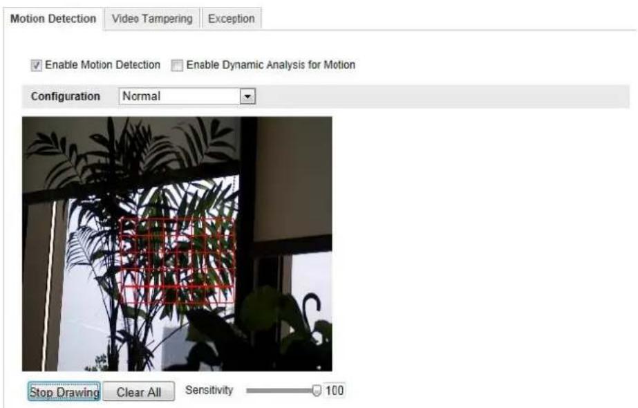
Figure 5-33 Enable Motion Detection
(4) Click Draw Area. Click and drag the mouse on the live video to draw a motion detection area.
(5)Click Stop Drawing to finish drawing one area.
(6)(Optional) Click Clear All to clear all of the areas.
(7)(Optional) Move the slider to set the sensitivity of the detection.
2. Set the Arming Schedule for Motion Detection.
Steps:

bar
Arming Schedule | Day | Arming Schedule | |---|---| | Mon | 1 | | Tue | 1 | | Wed | 1 | | Thu | 1 | | Fri | 1 | | Sat | 1 | | Sun | 1 |Figure 5-34 Arming Time
(1) Click Edit to edit the arming schedule. The Figure 6-34 shows the editing interface of the arming schedule.
(2) Choose the day you want to set the arming schedule.
(3)Click to set the time period for the arming schedule.
(4)(Optional) After you set the arming schedule, you can copy the schedule to other days.
(5)Click OK to save the settings.
Note: The time of each period can't be overlapped. Up to 4 periods can be configured for each day.

Figure 5-35 Arming Time Schedule
- Set the Alarm Actions for Motion Detection.
Check the checkbox to select the linkage method. Notify surveillance center, send email, upload to FTP, trigger channel and trigger alarm output are selectable.
You can specify the linkage method when an event occurs.
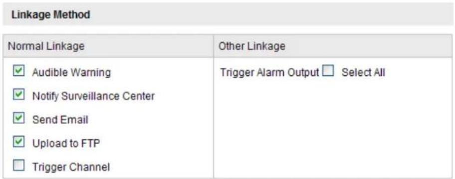
Figure 5-36 Linkage Method
- Audible Warning
Trigger the audible warning locally. And it only supported by the device have the audio output.
- Notify Surveillance Center
Send an exception or alarm signal to remote management software when an event occurs.
- Send Email
Send an email with alarm information to a user or users when an event occurs.
Note: To send the Email when an event occurs, you need to refer to Section 6.6.6 to set the related parameters.
- Upload to FTP
Capture the image when an alarm is triggered and upload the picture to a FTP server.
Note: Set the FTP address and the remote FTP server first. Refer to Section 6.3.10 for detailed information.
- Trigger Channel
The video will be recorded when the motion is detected. You have to set the recording schedule to realize this function. Please refer to Section 7.2 for detailed information.
- Trigger Alarm Output
Trigger one or more external alarm outputs when an event occurs.
Note: To trigger an alarm output when an event occurs, please refer to Section 6.6.4 to set the related parameters.
Expert Configuration
Expert mode is mainly used to configure the sensitivity and proportion of object on area of each area for different day/night switch.

Figure 5-37 Expert Mode of Motion Detection
● Day/Night Switch OFF
Steps:
(1) Draw the detection area as in the normal configuration mode. Up to 8 areas are supported.
(2)Select OFF for Switch Day and Night Settings.
(3) Select the area by clicking the area No.
(4)Slide the cursor to adjust the sensitivity and proportion of object on the area for the selected area.
(5) Set the arming schedule and linkage method as in the normal configuration mode.
(6) Click Save to save the settings.
● Day/Night Auto-Switch
Steps:
(1) Draw the detection area as in the normal configuration mode. Up to 8 areas are supported.
(2)Select Auto-Switch for Switch Day and Night Settings.
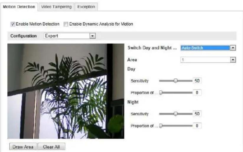
Figure 5-38 Day/Night Auto-Switch
(3) Select the area by clicking the area No.
(4)Slide the cursor to adjust the sensitivity and proportion of object on the area for the selected area in the daytime.
(5)Slide the cursor to adjust the sensitivity and proportion of object on the area for the selected area at night.
(6)Set the arming schedule and linkage method as in the normal configuration mode.
(7) Click Save to save the settings.
● Day/Night Scheduled-Switch
(1) Draw the detection area as in the normal configuration mode. Up to 8 areas are supported.
(2)Select Scheduled-Switch for Switch Day and Night Settings.

Figure 5-39 Day/Night Scheduled-Switch
(3) Select the start time and the end time for the switch timing.
(4) Select the area by clicking the area No.
(5)Slide the cursor to adjust the sensitivity and proportion of object on the area for the selected area in the daytime.
(6)Slide the cursor to adjust the sensitivity and proportion of object on the area for the selected area at night.
(7) Set the arming schedule and linkage method as in the normal configuration mode.
(8) Click Save to save the settings.
5.6.2 Configuring Video Tampering Alarm
Purpose:
You can configure the camera to trigger the alarm when the lens is covered and take alarm response action.
Steps:
- Enter the video tampering Settings interface:
Configuration > Advanced Configuration > Events > Video Tampering

Figure 5-40 Video Tampering Alarm
- Check Enable Video Tampering checkbox to enable the video tampering detection.
- Set the video tampering area; refer to Task 1 Set the Motion Detection Area in Section 6.6.1.
- Click Edit to edit the arming schedule for video tampering. The arming schedule configuration is the same as the setting of the arming schedule for motion detection.
Refer to Task 2 Set the Arming Schedule for Motion Detection in Section 6.6.1. - Check the checkbox to select the linkage method taken for the video tampering. Audible warning, notify surveillance center, send email and trigger alarm output are selectable. Please refer to Task 3 Set the Alarm Actions for Motion Detection in Section 6.6.1.
- Click Save to save the settings.
5.6.3 Configuring Alarm Input
Steps:
- Enter the Alarm Input Settings interface:
Configuration > Advanced Configuration> Events > Alarm Input:
- Choose the alarm input No. and the Alarm Type. The alarm type can be NO
(Normally Open) and NC (Normally Closed). Edit the name to set a name for the alarm input (optional).
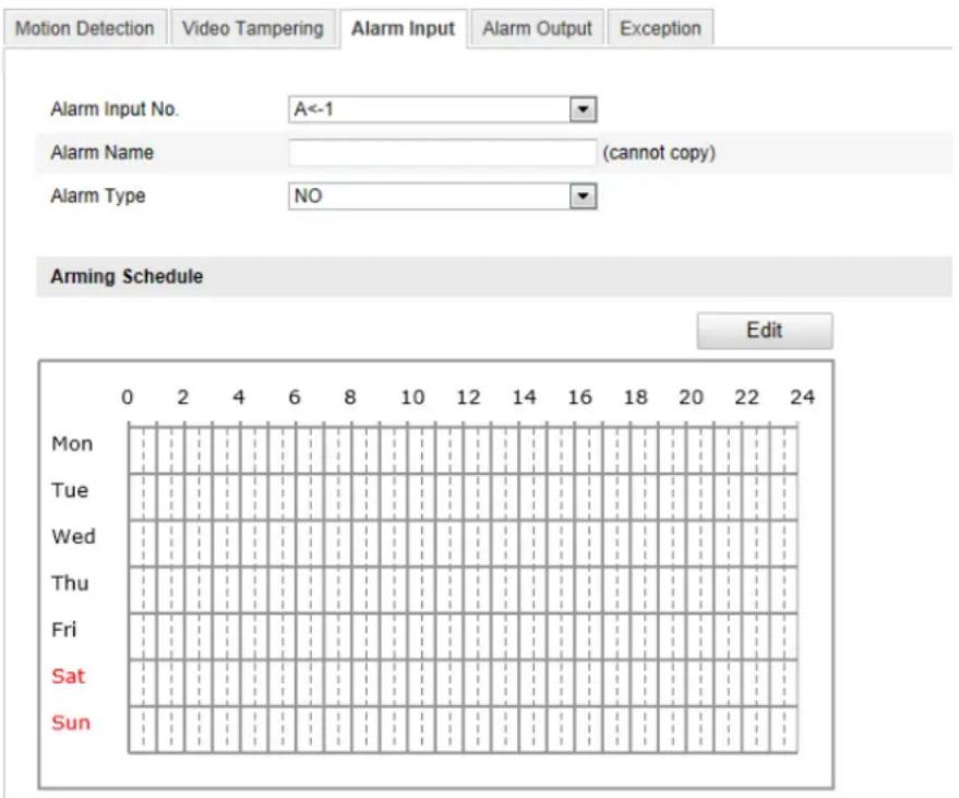
Figure 5-41 Alarm Input Settings
- Click Edit to set the arming schedule for the alarm input. Refer to Task 2 Set the Arming Schedule for Motion Detection in Section 6.6.1.
- Check the checkbox to select the linkage method taken for the alarm input. Refer to Task 3 Set the Alarm Actions for Motion Detection in Section 6.6.1.
- You can also choose the PTZ linking for the alarm input if your camera is installed with a pan/tilt unit. Check the relative checkbox and select the No. to enable Preset Calling, Patrol Calling or Pattern Calling.
- You can copy your settings to other alarm inputs.
- Click Save to save the settings.
5.6.4 Configuring Alarm Output
Steps:
- Enter the Alarm Output Settings interface:
Configuration>Advanced Configuration>Events >Alarm Output
- Select one alarm output channel in the Alarm Output drop-down list. You can also set a name for the alarm output (optional).
- The Delay time can be set to 5sec, 10sec, 30sec, 1min, 2min, 5min, 10min or Manual. The delay time refers to the time duration that the alarm output remains in effect after alarm occurs.
- Click Edit to enter the Edit Schedule Time interface. The time schedule configuration is the same as the settings of the arming schedule for motion detection Refer to Task 2 Set the Arming Schedule for Motion Detection in Section 6.6.1.
- You can copy the settings to other alarm outputs.
- Click Save to save the settings.

Figure 5-42 Alarm Output Settings
5.6.5 Handling Exceptions
The exception type can be HDD full, HDD error, network disconnected, IP address conflict and illegal login to the cameras.
Steps:
- Enter the Exception Settings interface:
Configuration > Advanced Configuration> Events > Exception
- Check the checkbox to set the actions taken for the Exception alarm. Refer to
Task 3 Set the Alarm Actions Taken for Motion Detection in Section 6.6.1.

Figure 5-43 Exception Settings
- Click Save to save the settings.
5.6.6 Configuring Line Crossing Detection
Video Content Analysis for Line Crossing is more than just motion detection. It is recognition of specific motion in a specific direction across a specific demarcation.
This function can be used for detecting people, vehicles and objects crossing a pre-defined boundary. The line crossing direction can be set as bidirectional, from left to right or from right to left. The camera and NVR can enable a linkage between VCA alarms and other actions when detecting exceptional events, such as people, vehicles and objects crossing a virtual line.
Steps:
- Check the Enable Line Crossing Detection checkbox.
- Click the Draw Area, and a crossing plane will show on the image.
- Click on the line, and you will see two red squares on each end, drag each of these red squares to define the arming line. Once the line has been defined, clicking on the 'Draw Area' button allows the line to be repositioned. "Clear" will erase the line. Only one line per camera is allowed.

Figure 5-44 Draw Crossing Line
And you can select the directions as A<->B, A->B, and B->A.
- A<->B: The arrows on both the A and B side show. When an object crosses the plane in either direction it can be detected and alarms are triggered.
•A->B: Only the arrow on the B side shows. Only objects crossing the configured line from the A side to the B side can be detected. -
B->A: Only the arrow on the A side shows. Only objects crossing the configured line from the B side to the A side can be detected.
-
Set the sensitivity [1\~100].
- Click Save to save the settings.
5.6.7 Configuring Intrusion Detection
Video Content Analysis is more than just motion detection. It is recognition of specific motion that carries a person or object into a specific area where it remains for a specific time. Intrusion detection can set an area in the surveillance scene and once the area is been entered, a set of alarm action is triggered. BE SURE TO SET UP RESPONSES TO VCA EVENTS IN THE NVR SIDE CAMERA MANAGEMENT VCA MENU.
This function can be used for detecting whether there are people, vehicles and objects entering into and remaining in the pre-defined region longer than a set duration. You can set the duration for the alarm response actions, such as full screen monitoring, audible warning. Intrusion Detection (area violation, with loitering time) allows the definition of a single area (an area is defined by four points, so it is generally a ‘quadrilateral’. It can be square, rectangular, or a trapezoid that can taper to the shape of a triangle). There are control settings for sensitivity, percentage of area, and the amount of time the percentage/sensitivity indicates a change before a VCA event occurs. This would allow alerts due to persons loitering, or objects left behind, while ignoring persons and objects passing through an area. This is intrusion detection; the scene is analyzed for movement INTO the area which results in a lasting change. Movement OUT of the area is not flagged, so while this capability may flag objects left behind, it will not respond to missing objects.
Steps:
- Check the Enable Intrusion Detection checkbox.
- Click Draw Area, and then draw a rectangle on the image as a defense region. Note: when you draw the rectangle, all lines should connect end to end to each other. Four individual points must be defined. Click 'Stop Drawing' when complete. Click 'Draw Area' again to drag any of the corners and redefine the area. Or 'Clear' the area and draw it again.
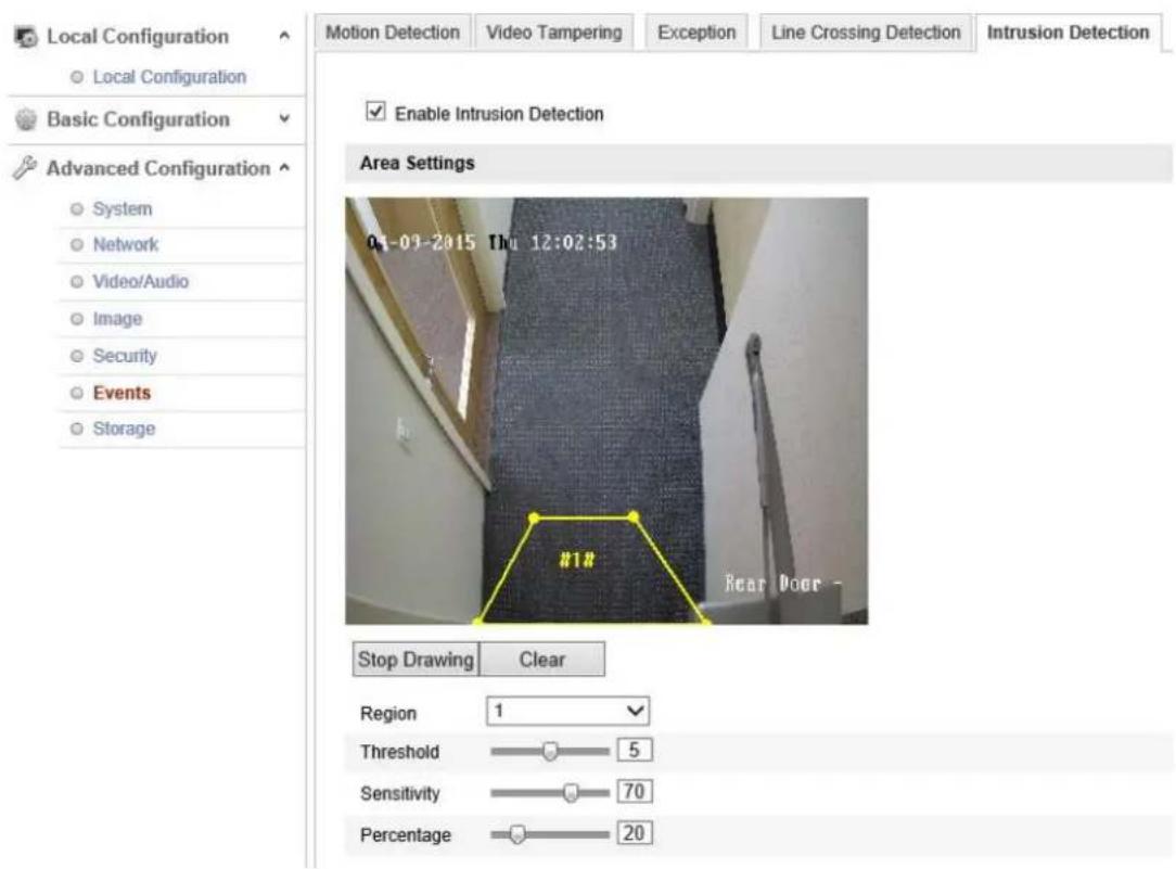
Figure 5-45 Configuring Intrusion Area
You can click Clear to clear the area you have drawn.
The detection area parameters can be set separately.
➢ Threshold: Range [0-10s], the threshold for the time the object loiters in the region. If you set the value as 0, alarm is triggered immediately after the object enters the region.
➢ Sensitivity: Range [1-100]. Sensitivity relates to the difference in brightness or shading which distinguishes one object from another or from the background.
➢ Percentage: Range [1-100]. Percentage relates to relative size of objects to be detected versus the size of the defined detection area. For example, when you set the percentage as 50%, the object must obscure half the region to trigger an alarm.
Arming Schedule is configured to set the times you want the function to be enabled.
- Click Edit to set the arming schedule.
- Choose to trigger alarm actions as Notify Surveillance Center, Send Email, Upload to FTP and Trigger Channel or trigger the Alarm Output.
- Click Save to save the settings.

bar
| Day | Time (minutes) | |---|---| | Mon | 0 | | Tue | 2 | | Wed | 4 | | Thu | 6 | | Fri | 8 | | Sat | 10 | | Sun | 12 | | Mon | 14 | | Tue | 16 | | Wed | 18 | | Thu | 20 | | Fri | 22 | | Sat | 24 |Linkage Method
| Normal Linkage | Other Linkage |
| ☑ Notify Surveillance Center☐ Send Email☐ Upload to FTP☑ Trigger Channel | Trigger Alarm Output ☐ Select All |
Chapter 6 Storage Settings
Before you start:
To configure record settings, please make sure that you have the network storage device within the network or the SD card inserted in your camera.
6.1 Configuring NAS Settings
Before you start:
The network disk should be available on the network and properly configured to store the recorded files, log files, etc.
Steps:
1. Add the network disk
(1) Enter the NAS (Network-Attached Storage) Settings interface:
Configuration > Advanced Configuration > Storage > NAS
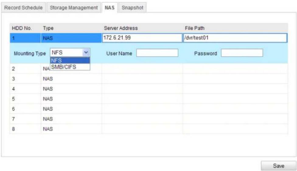
Figure 6-1 Add Network Disk
(2) Enter the IP address of the network disk, and enter the file path.
(3) Select the mounting type. NFS and SMB/CIFS are selectable. And you can set the user name and password to guarantee the security if SMB/CIFS is selected.
Note: Please refer to the User Manual for your NAS device for details about
creating the file path.
(4) Click Save to add the network disk.
- Initialize the added network disk.
(1) Enter the HDD Settings interface (Advanced Configuration > Storage > Storage Management), in which you can view the capacity, free space, status, type and property of the disk.

Figure 6-2 Storage Management Interface
(2) If the status of the disk is Uninitialized, check the corresponding checkbox to select the disk and click Format to start initializing the disk.
When the initialization completed, the status of disk will become Normal.

Figure 6-3 View Disk Status
- Define the quota for record and pictures.
(1) Input the quota percentage for picture and for record.
(2) Click Save and refresh the browser page to activate the settings.

Figure 6-4 Quota Settings
Notes:
● Up to 8 NAS disks can be connected to the camera.
- To initialize and use the SD card after insert it to the camera, please refer to the steps of NAS disk initialization.
6.2 Configuring Recording Schedule
Purpose:
There are two kinds of recording for the cameras: manual recording and scheduled recording. For the manual recording, refer to Section 5.3 Recording and Capturing Pictures Manually. In this section, you can follow the instructions to configure the scheduled recording. By default, the record files of scheduled recording are stored in the SD card (if supported) or in the network disk.
Steps:
- Enter the Record Schedule Settings interface:
Configuration > Advanced Configuration> Storage > Record Schedule

Figure 6-5 Recording Schedule Interface
- Check the checkbox of Enable Record Schedule to enable scheduled recording.
- Set the record parameters of the camera.
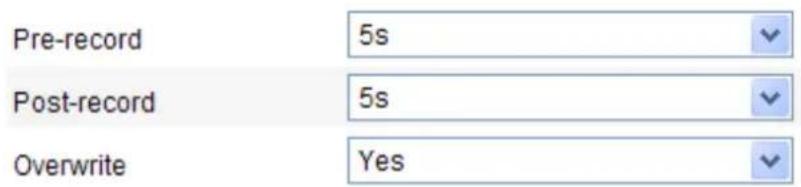
Figure 6-6 Record Parameters
- Pre-record: The time you set to start recording before the scheduled time or the event. For example, if an alarm triggers recording at 10:00, and the pre-record time is set as 5 seconds, the camera starts to record at 9:59:55.
The Pre-record time can be configured as No Pre-record, 5 s, 10 s, 15 s, 20 s, 25 s, 30 s or not limited.
- Post-record: The time you set to stop recording after the scheduled time or the event. For example, if an alarm triggered recording ends at 11:00, and the post-record time is set as 5 seconds, the camera records until 11:00:05.
The Post-record time can be configured as 5 s, 10 s, 30 s, 1 min, 2 min, 5 min
or 10 min.
Note: The record parameter configurations vary depending on the camera model.
- Click Edit to edit the record schedule.
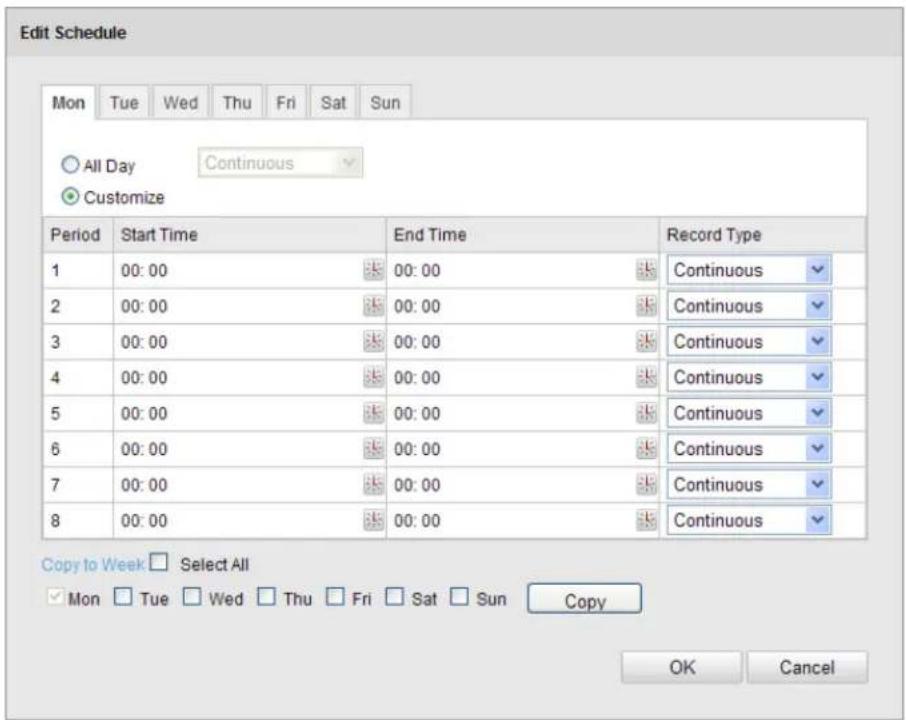
Figure 6-7 Record Schedule
- Choose the day to set the record schedule.
(1) Set all-day record or segment record:
If you want to configure the all-day recording, please check the All Day checkbox.
If you want to record in different time sections, check the Customize checkbox. Set the Start Time and End Time.
Note: The time of each segment can't be overlapped. Up to 4 segments can be configured.
(2) Select a Record Type. The record type can be Continuous, Motion Detection, Alarm, Motion | Alarm, Motion & Alarm, etc.
◆ Continuous
If you select Continuous, the video will be recorded automatically according to the time of the schedule.
◆ Record Triggered by Motion Detection
If you select Motion Detection, the video will be recorded when the motion is detected.
Besides configuring the recording schedule, you have to set the motion detection area and check the checkbox of Trigger Channel in the Linkage Method of Motion Detection Settings interface. For detailed information,
please refer to the Step 1 Set the Motion Detection Area in the Section 6.6.1.
◆ Record Triggered by Alarm
If you select Alarm, the video will be recorded when the alarm is triggered via the external alarm input channels.
Besides configuring the recording schedule, you have to set the Alarm Type and check the checkbox of Trigger Channel in the Linkage Method of Alarm Input Settings interface. For detailed information, please refer to Section 6.6.4.
◆ Record Triggered by Motion & Alarm
If you select Motion & Alarm, the video will be recorded when the motion and alarm are triggered at the same time.
Besides configuring the recording schedule, you have to configure the settings on the Motion Detection and Alarm Input Settings interfaces.
Please refer to Section 6.6.1 and Section 6.6.4 for detailed information.
◆ Record Triggered by Motion | Alarm
If you select Motion | Alarm, the video will be recorded when the external alarm is triggered or the motion is detected.
Besides configuring the recording schedule, you have to configure the settings on the Motion Detection and Alarm Input Settings interfaces.
Please refer to Section 6.6.1 and Section 6.6.4 for detailed information.
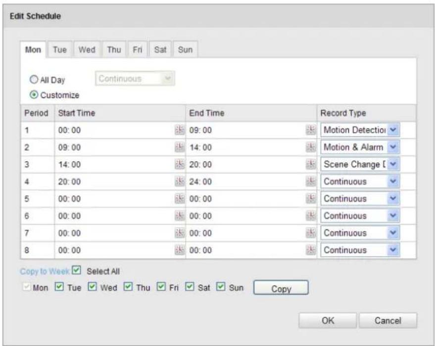
Figure 6-8 Edit Record Schedule
(3) Check the checkbox of Select All and click Copy to copy settings of this day to the whole week. You can also check any of the checkboxes before the date and click Copy.
(4) Click OK to save the settings and exit the Edit Record Schedule interface.
- Click Save to save the settings.
6.3 Configuring Snapshot Settings
Purpose:
You can configure the scheduled snapshot and event-triggered snapshot. The captured picture can be stored in the SD card (if supported) or the netHDD (For detailed information about netHDD, please refer to Section 7.1 Configuring NAS Settings). You can also upload the captured pictures to a FTP server.
Basic Settings
Steps:
- Enter the Snapshot Settings interface:
Configuration > Advanced Configuration > Storage > Snapshot
- Check the Enable Timing Snapshot checkbox to enable continuous snapshot.
Check the Enable Event-triggered Snapshot checkbox to check event-triggered snapshot.
- Select the quality of the snapshot.
- Set the time interval between two snapshots.
- Click Save to save the settings.
Uploading to FTP
You can follow below configuration instructions to upload the snapshots to FTP.
- Upload continuous snapshots to FTP
Steps:
1) Configure the FTP settings and check Upload Picture checkbox in FTP Settings interface. Please refer to Section 6.3.10 Configuring FTP Settings for more details to configure FTP parameters.
2) Check the Enable Timing Snapshot checkbox.
- Upload event-triggered snapshots to FTP
Steps:
1) Configure the FTP settings and check Upload Picture checkbox in FTP Settings interface. Please refer to Section 6.3.8 Configuring FTP Settings for more details to configure FTP parameters.
2) Check Upload Picture checkbox in Motion Detection Settings or Alarm Input interface. Please refer to Step 3 Set the Alarm Actions Taken for Motion Detection in Section 6.6.1, or Step 4 Configuring External Alarm Input in Section 6.6.4.
3) Check the Enable Event-triggered Snapshot checkbox.
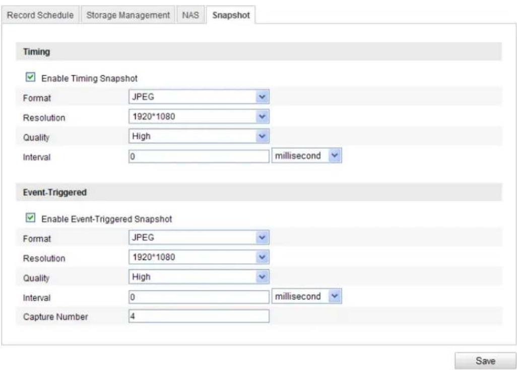
Figure 6-9 Snapshot Settings
Chapter 7 Playback
Purpose:
This section explains how to view the remotely recorded video files stored in the network disks or SD cards.
Steps:
- Click Playback on the menu bar to enter playback interface.

Figure 7-1 Playback Interface
- Select the date and click Search.

Figure 7-2 Search Video
- Click to play the video files found on this date.
The toolbar on the bottom of Playback interface can be used to control playing process.

Figure 7-3 Playback Toolbar
Table 7-1 Description of the buttons
| Button | Operation | Button | Operation |
 | Play |  | Capture a picture |
 | Pause |  | Start/Stop clipping video files |
 | Stop |  | Audio on and adjust volume/Mute |
 | |||
 | Speed down |  | Download video files |
 | Speed up |  | Download captured pictures |
 | Playback by frame |  | Enable/Disable digital zoom |
Note: You can choose the file paths locally for downloaded playback video files and pictures in Local Configuration interface. Please refer to Section 6.1 for details.
Drag the progress bar with the mouse to locate the exact playback point. You can also input the time and click → to locate the playback point in the Set playback time field. You can also click to zoom out/in the progress bar.

Figure 7-4 Set Playback Time

Figure 7-5 Progress Bar
The different colors of the video on the progress bar stand for the different video types.

Figure 7-6 Video Types
Chapter 8 Log Searching
Purpose:
The operation, alarm, exception and information of the camera can be stored in log files. You can also export the log files on your demand.
Before you start:
Please configure network storage for the camera or insert a SD card in the camera.
Steps:
- Click Log on the menu bar to enter log searching interface.
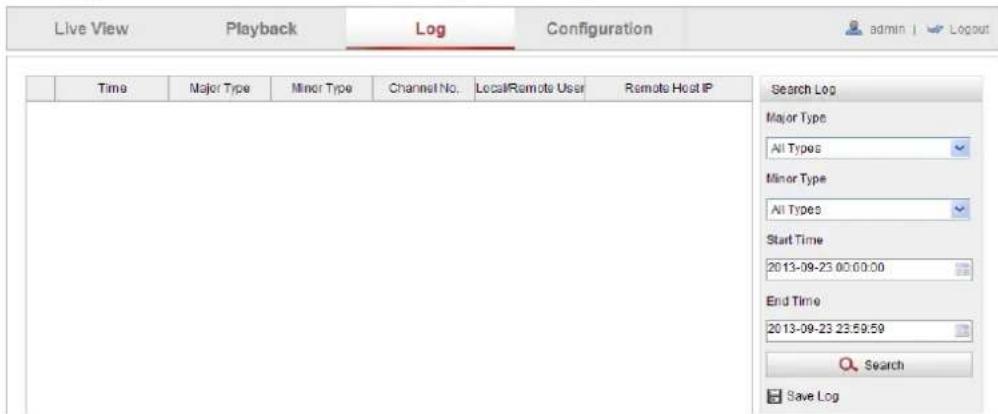
Figure 8-1 Log Searching Interface
- Set the log search conditions to specify the search, including the Major Type, Minor Type, Start Time and End Time.
- Click Search to search log files. The matched log files will be displayed on the Log interface.
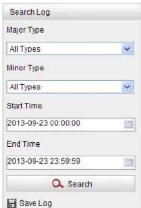
Figure 8-2 Log Searching
- To export the log files, click Save log to save the log files in your computer.
Chapter 9 Other Settings
9.1 Managing User Accounts
Enter the User Management interface:
Configuration >Basic Configuration> Security >User
Or Configuration > Advanced Configuration> Security > User
The admin user has access to create, modify or delete other accounts. Up to 15 user accounts can be created.

Figure 9-1 User Information
- Add a User
Steps:
- Click Add to add a user.
- Input the new User Name, select Level and input Password.
Note: The level indicates the permissions you give to the user. You can define the user as Operator or User.
- In the Basic Permission field and Camera Configuration field, you can check or uncheck the permissions for the new user.
- Click OK to finish the user addition.

Figure 9-2 Add a User
- Modify a User
Steps:
- Left-click to select the user from the list and click Modify.
- Modify the User Name, Level or Password.
- In the Basic Permission field and Camera Configuration field, you can check or uncheck the permissions.
- Click OK to finish the user modification.

Figure 9-3 Modify a User
- Delete a User
Steps:
- Click to select the user you want to delete and click Delete.
- Click OK on the pop-up dialogue box to delete the user.
9.2 Configuring RTSP Authentication
Purpose:
You can specifically secure the stream data of live view.
Steps:
1. Enter the RTSP Authentication interface:
Configuration> Advanced Configuration> Security > RTSP Authentication

Figure 9-4 RTSP Authentication
- Select the Authentication type basic or disable in the drop-down list to enable or disable the RTSP authentication.
Note: If you disable the RTSP authentication, anyone can access the video stream by the RTSP protocol via the IP address.
- Click Save to save the settings.
9.3 Anonymous Visit
Purpose:
Enabling this function allows access by anyone who doesn't have a user name and password for the camera.
Steps:
- Enter the Anonymous Visit interface:
Configuration> Advanced Configuration> Security > Anonymous Visit

Figure 9-5 Anonymous Visit
- Set the Anonymous Visit permission Enable or Disable in the drop-down list to enable or disable the anonymous visit.
- Click Save to save the settings.
There will be a checkbox for “Anonymous” presented on the LOGIN screen when this function is active.
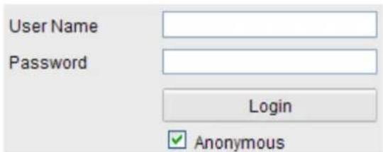
Figure 9-6 Login Interface with an Anonymous Checkbox
- Users may check the checkbox for Anonymous and then click Login.
Note: Only live view is available for the anonymous user.
9.4 IP Address Filter
Purpose:
This function makes it possible for access control based on the IP address of the device attempting to access the camera.
Steps:
- Enter the IP Address Filter interface:
Configuration> Advanced Configuration> Security > IP Address Filter

Figure 9-7 IP Address Filter Interface
- Check the checkbox of Enable IP Address Filter.
- Select the type of IP Address Filter in the drop-down list, Forbidden and Allowed are selectable.
- Set the IP Address Filter list.
- Add an IP Address
Steps:
(1) Click the Add to add an IP.
(2) Input the IP Adreess.

Figure 9-8 Add an IP
(3) Click the OK to finish adding.
- Modify an IP Address
Steps:
(1) Left-click an IP address from filter list and click Modify.
(2) Modify the IP address in the text filed.
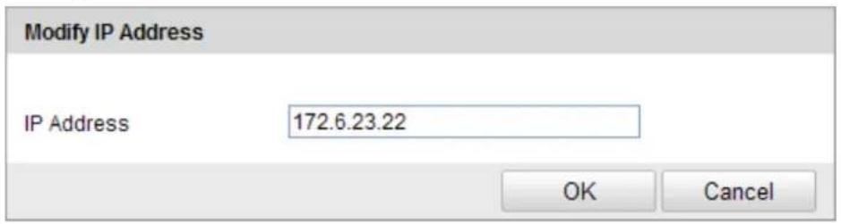
Figure 9-9 Modify an IP
(3) Click the OK to finish modifying.
- Delete an IP Address Left-click an IP address from filter list and click Delete.
- Delete all IP Addresses Click Clear to delete all the IP addresses.
- Click Save to save the settings.
9.5 Viewing Device Information
Enter the Device Information interface:
Configuration > Basic Configuration> System > Device Information Or Configuration > Advanced Configuration> System > Device Information In the Device Information interface, you can edit the Device Name.
Other information about the network camera, such as Model, Serial No., Firmware Version, Encoding Version, Number of Channels, Number of HDDs, Number of Alarm Inputs and Number of Alarm Outputs are displayed. The information cannot be changed in this menu. It is a reference for maintenance or modification in the future.

Figure 9-10 Device Information
9.6 Maintenance
9.6.1 Rebooting the Camera
Steps:
- Enter the Maintenance interface:
Configuration > Basic Configuration> System > Maintenance
Or Configuration > Advanced Configuration> System > Maintenance
- Click Reboot to reboot the network camera.

Figure 9-11 Reboot the Device
9.6.2 Restoring Default Settings
Steps:
- Enter the Maintenance interface:
Configuration > Basic Configuration > System > Maintenance
Or Configuration > Advanced Configuration> System > Maintenance
- Click Restore or Default to restore the default settings.

Figure 9-12 Restore Default Settings
Note: After restoring the default settings, the IP address is also restored to the default IP address, please be careful for this action.
9.6.3 Exporting / Importing Configuration File
Purpose:
Configuration file is used for the batch configuration of the camera, which can simplify the configuration steps when there are a lot of cameras needing configuring.
Steps:
Enter the Maintenance interface:
Configuration > Basic Configuration> System > Maintenance
Or Configuration > Advanced Configuration> System > Maintenance
- Click Export to export the current configuration file, and save it to the certain place.
-
Click Browse to select the saved configuration file and then click Import to start importing configuration file.
Note: You need to reboot the camera after importing configuration file. -
Click Export and set the saving path to save the configuration file in local storage.
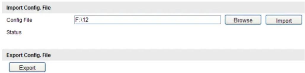
Figure 9-13 Import/Export Configuration File
9.6.4 Upgrading the System
Steps:
- Enter the Maintenance interface:
Configuration > Basic Configuration> System > Maintenance
Or Configuration > Advanced Configuration> System > Maintenance
- Click Browse to select the local upgrade file and then click Upgrade to start remote upgrade.
Note: The upgrading process will take 1 to 10 minutes. Please don't disconnect power of the camera during the process. The camera reboots automatically after upgrading.

Figure 9-14 Remote Upgrade
9.7 RS-232 Settings
Purpose:
The RS-232 port can be used in two ways:
- Parameters Configuration: Connect a computer to the camera through the serial port. Device parameters can be configured by using software such as HyperTerminal. The serial port parameters must be the same as the serial port parameters of the camera.
- Transparent Channel: Connect a serial device directly to the camera. The serial device will be controlled remotely by the computer through the network.
Steps:
- Enter RS-232 Port Setting interface:
Configuration> Advanced Configuration> System > RS232
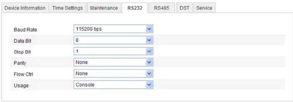
Figure 9-15 RS-232 Settings
Note: If you want to connect the camera by the RS-232 port, the parameters of the RS-232 should be exactly the same with the parameters you configured here.
- Click Save to save the settings.
Appendix
Appendix 1 SADP Software Introduction
● Description of SADP
OMNI Finder (formerly SADP - Search Active Devices Protocol) is a user-friendly and installation-free online device search/discovery tool. It searches the active online devices within your subnet and displays information about the devices. You can also modify the basic network information of the devices using this software.
- Search active devices online
◆ Search online devices automatically
After launching the OMNI Finder/SADP software, it automatically searches for online devices every 15 seconds on the subnet where your computer is located. It displays useful information about the discovered devices in the Online Devices interface. Device information including the device type, IP address, port number, gateway, etc. will be displayed.
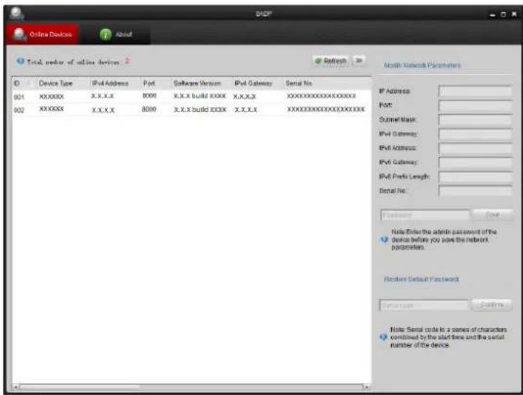
Figure A.1.1 Search Results
Note: Devices can be searched and displayed in the list in 15 seconds after they come online; they will be removed from the list in 45 seconds after they go offline.
◆ Search online devices manually
You can also click Refresh to refresh the online device list manually. The
newly discovered devices will be added to the list.
Note: You can click △ or ▽ on each column heading to order the information; you can click >> to expand the device table and hide the network parameter panel on the right side, or click << to show the network parameter panel.
- Modify network parameters
Steps:
- Select the device to be modified in the device list, and the network parameters for the device will be displayed in the Modify Network Parameters panel on the right side.
- Edit the modifiable network parameters, e.g. IP address and port number, gateway
- Enter the password of the admin account for the device in the Password field and click to save the changes.

Figure A.1.2 Modify Network Parameters
-
Note the "date" displayed in the device data.
-
Contact our technical engineers with your serial number and date to get a serial code.
- Input the code in the Serial code field and click Confirm to restore the default password.
This code is only valid for the specific date; the date is typically the day on which the unit was last rebooted. If the unit is rebooted between the time the serial code is requested and the time it is entered, the serial code becomes invalid.
One approach is to specify a future date (e.g. two business days in the future). Request the code; reboot the unit on the specified day, then enter the serial code which is valid on for that reboot date.
Appendix 2 Port Mapping
The following settings are for TP-LINK router (TL-WR641G). The settings vary depending on different models of routers.
Steps:
- Select the WAN Connection Type, as shown below:

Figure A.2.1 Select the WAN Connection Type
- Set the LAN parameters of the router as in the following figure, including IP address and subnet mask settings.
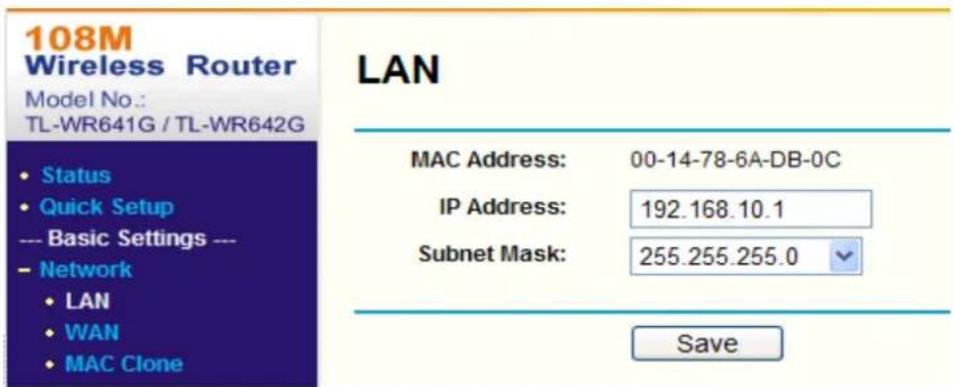
Figure A.2.2 Set the LAN parameters
- Set the port mapping in the virtual severs of Forwarding. By default, camera uses port 80, 8000 and 554. You can change these ports value with web browser or client software.
Example:
When the cameras are connected to the same router, you can configure the ports of a camera as 80, 8000, and 554 with IP address 192.168.1.23, and the ports of
another camera as 81, 8001, 555, 8201 with IP 192.168.1.24. Refer to the steps as below:
Steps:
- As the settings mentioned above, map the port 80, 8000, 554 and 8200 for the network camera at 192.168.1.23
- Map the port 81, 8001, 555 and 8201 for the network camera at 192.168.1.24.
- Enable ALL or TCP protocols.
- Check the Enable checkbox and click Save.
Virtual Servers

Figure A.2.3 Port Mapping
Note: The port of the network camera cannot conflict with other ports. For example, some web management port of the router is 80. Change the camera port if it is the same as the management port.
KT&C America
www.kfncusa.com
New Jersey Office
40 Lane Road 1st Floor Fairfield, NJ 07006
1:973 276 0118 F:973 276 0116
New York Office
200 Pkwy Drive South Suite 200 Houppouge, NY 11788
T: 631 864 0118 F: 631 864 0116
California Office
3240 Wilshire Blvd Suite 501 Los Angeles, CA 90010
F:213 381 0061 F:213 381 0064
- Scalable IP Solutions
- Plug-and-Play Network Cameras
- KNC-p3 Series
- About This Guide
- DISCLAIMER STATEMENT
- Regulatory Information
- FCC Information
- FCC Conditions
- EU Conformity Statement
- Safety Instructions
- Warnings:
- Cautions:
- Table of Contents
- Chapter 1 System Requirements ....7
- Chapter 2 Network Connection....8
- Setting the Network Camera over the LAN....8
- Accessing a Network Camera over a WAN.... 10
- Chapter 3 Web Access to the Network Camera ....14
- Chapter 4 Web Live View....18
- Chapter 5 Network Camera Configuration....23
- Configuring Video and Audio Settings.... 41
- Configuring Image Parameters 45
- Configuring and Handling Alarms.... 52
- Chapter 6 Storage Settings....68
- Chapter 7 Playback....77
- Chapter 8 Log Searching....79
- Chapter 9 Other Settings....80
- Appendix 90
- Chapter 1 System Requirements
- Chapter 2 Network Connection
- Before you start:
- Setting the Network Camera over the LAN
- Purpose:
- Wiring over the LAN
- Detecting and Changing the IP Address
- Steps:
- Notes:
- Accessing a Network Camera over a WAN
- Static IP Connection
- Dynamic IP Connection
- - Connecting the network camera via a router
- - Connecting the network camera via a DSL modem connection requiring login authentication
- Chapter 3 Web Access to the Network Camera
- System Requirements:
- Accessing by OMNI CMS Software
- Accessing by CMS
- Accessing by OMNI Remote Software
- Chapter 4 Web Live View
- Live View Page
- Menu Bar:
- Display Control:
- Live View Window:
- Toolbar:
- PTZ Control:
- Preset Setting/Calling:
- Starting Live View
- Recording and Capturing Pictures Manually
- Operating PTZ Control
- PTZ Control Panel
- Setting / Calling a Preset
- - Setting a Preset:
- - Calling a Preset:
- Chapter 5 Network Camera Configuration
- Configuring Local Parameters
- Configuring Time Settings
- Configuring Network Settings
- Configuring TCP/IP Settings
- Configuring Port Settings
- Configuring PPPoE Settings
- Configuring DDNS Settings
- - SIMPLEDDNS
- Configuring SNMP Settings
- Configuring 802.1X Settings
- Configuring QoS Settings
- Configuring UPnPTM Settings
- Email Sending Triggered by Alarm
- Configuring NAT (Network Address Translation) Settings
- Configuring FTP Settings
- Configuring Video and Audio Settings
- Configuring Video Settings
- Video Type:
- Resolution:
- Bitrate Type:
- Video Quality:
- Frame Rate:
- Max. Bitrate:
- Video Encoding:
- Profile:
- I Frame Interval:
- Configuring Audio Settings
- Configuring ROI Encoding
- Configuring Image Parameters
- Configuring Display Settings
- Note:
- Day/night Auto-switch
- ◆ Image Adjustment
- ◆ Exposure Settings
- ◆ Day/Night Switch
- ◆ Backlight Settings
- White Balance
- ◆ Image Enhancement
- ♦ Video Adjustment
- Day/Night Scheduled-Switch
- Configuring OSD Settings
- Configuring Text Overlay Settings
- Configuring Privacy Mask
- Configuring and Handling Alarms
- Configuring Motion Detection
- Normal Configuration
- Tasks:
- Set the Arming Schedule for Motion Detection.
- - Audible Warning
- - Notify Surveillance Center
- - Send Email
- - Upload to FTP
- - Trigger Channel
- - Trigger Alarm Output
- Expert Configuration
- Configuring Video Tampering Alarm
- Configuring Alarm Input
- Configuring Alarm Output
- Configuration>Advanced Configuration>Events >Alarm Output
- Handling Exceptions
- Configuration > Advanced Configuration> Events > Exception
- Configuring Line Crossing Detection
- Configuring Intrusion Detection
- Arming Schedule is configured to set the times you want the function to be enabled.
- Chapter 6 Storage Settings
- Configuring NAS Settings
- Add the network disk
- Configuring Recording Schedule
- ◆ Record Triggered by Motion Detection
- ◆ Record Triggered by Alarm
- ◆ Record Triggered by Motion & Alarm
- ◆ Record Triggered by Motion | Alarm
- Configuring Snapshot Settings
- Basic Settings
- Uploading to FTP
- Chapter 7 Playback
- Chapter 8 Log Searching
- Chapter 9 Other Settings
- Managing User Accounts
- - Delete a User
- Configuring RTSP Authentication
- Enter the RTSP Authentication interface:
- Anonymous Visit
- IP Address Filter
- Viewing Device Information
- Maintenance
- Rebooting the Camera
- Restoring Default Settings
- Exporting / Importing Configuration File
- Upgrading the System
- RS-232 Settings
- Appendix
- Appendix 1 SADP Software Introduction
- ● Description of SADP
- - Search active devices online
- ◆ Search online devices automatically
- ◆ Search online devices manually
- - Modify network parameters
- Appendix 2 Port Mapping
- Example:
Brand : KT&C
Model : KNC-P3BR12IR
Category : Security Camera