
DSRXL - Audio-Video Distribution StarTech.com - Free user manual and instructions
Find the device manual for free DSRXL StarTech.com in PDF.

| Product Type | HDMI Distribution Amplifier |
| Brand | StarTech.com |
| Model | DSRXL |
| Category | Audio-Video Distribution |
| Number of Inputs | 1 HDMI |
| Number of Outputs | 4 HDMI |
| Max Resolution | 3840x2160 @ 60Hz (4K) |
| Supported Audio Formats | LPCM, Dolby Digital, DTS |
| HDCP Support | HDCP 2.2 |
| Video Bandwidth | 18 Gbps |
| Dimensions (L x W x H) | 200 x 75 x 25 mm |
| Weight | 350 g |
| Power Supply | DC 5V, 2A (included) |
| Enclosure Material | Aluminum |
| Operating Temperature | 0°C to 40°C |
| Storage Temperature | -20°C to 60°C |
| Humidity | 5% to 85% RH (non-condensing) |
| Mounting Options | Desktop or wall-mount (brackets included) |
| Compliance | CE, FCC, RoHS |
| Warranty | 2 Years |
| Maintenance & Cleaning | Use a dry, soft cloth; avoid liquids and abrasives |
| Safety | Use only supplied power adapter; do not expose to moisture |
| Spare Parts & Repairability | Contact StarTech.com support for replacements; not user-serviceable |
| General Information | Designed for professional AV distribution in commercial and residential settings |
Frequently Asked Questions - DSRXL StarTech.com
User questions about DSRXL StarTech.com
0 question about this device. Answer the ones you know or ask your own.
Ask a new question about this device
Download the instructions for your Audio-Video Distribution in PDF format for free! Find your manual DSRXL - StarTech.com and take your electronic device back in hand. On this page are published all the documents necessary for the use of your device. DSRXL by StarTech.com.
USER MANUAL DSRXL StarTech.com
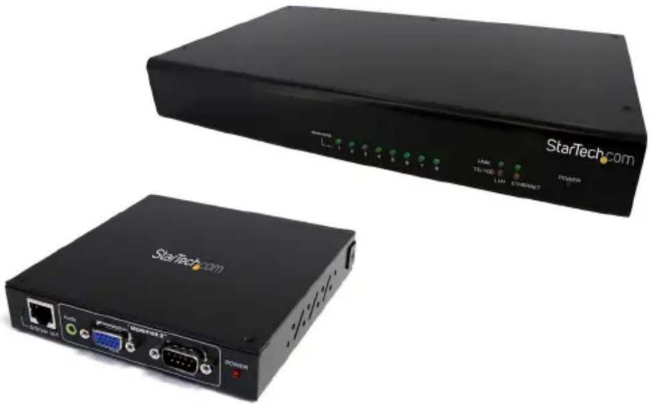
VGA over Cat5 Digital Signage Receiver for DS128 with RS232 & Audio
DS128
DSRXL
natural_image
Two black StarTech.com networking devices shown from front and back angles, no visible text or symbols on the devices themselves.*actual product may vary from photos
For the most up-to-date information, please visit: www.startech.com
FCC Compliance Statement
This equipment has been tested and found to comply with the limits for a Class B digital device, pursuant to part 15 of the FCC Rules. These limits are designed to provide reasonable protection against harmful interference in a residential installation. This equipment generates, uses and can radiate radio frequency energy and, if not installed and used in accordance with the instructions, may cause harmful interference to radio communications. However, there is no guarantee that interference will not occur in a particular installation. If this equipment does cause harmful interference to radio or television reception, which can be determined by turning the equipment off and on, the user is encouraged to try to correct the interference by one or more of the following measures:
• Reorient or relocate the receiving antenna.
- Increase the separation between the equipment and receiver.
- Connect the equipment into an outlet on a circuit different from that to which the receiver is connected.
- Consult the dealer or an experienced radio/TV technician for help.
Use of Trademarks, Registered Trademarks, and other Protected Names and Symbols
This manual may make reference to trademarks, registered trademarks, and other protected names and/or symbols of third-party companies not related in any way to StarTech.com. Where they occur these references are for illustrative purposes only and do not represent an endorsement of a product or service by StarTech.com, or an endorsement of the product(s) to which this manual applies by the third-party company in question. Regardless of any direct acknowledgement elsewhere in the body of this document, StarTech.com hereby acknowledges that all trademarks, registered trademarks, service marks, and other protected names and/or symbols contained in this manual and related documents are the property of their respective holders.
Table of Contents
Introduction ....1
Packaging Contents ....1
System Requirements....1
Installation 2
DSRXL Receiver Installation ....3
Driver Installation....3
How to Use ....4
DSNet Manager....4
DSRXL Video Configuration ....7
DSRXL Monitor Configuration ....8
Specifications ....10
Specifications 11
Technical Support 12
Warranty Information 12
Introduction
The StarTech.com's "DS" series of Cat5 Digital Signage Solutions with RS232 Serial and Audio offers a comprehensive audio and video extension system, with the added benefit of serial control. Compatible with virtually any VGA computer or Digital Signage media player, the DS128 VGA Splitter lets you deliver VGA video as well as the accompanying audio and serial control signals to Cat5 VGA Receivers (DSRXL - purchased separately), all through one Cat5 cable. The DSRXL receivers, then convert the signal back into distinct RS232 serial, VGA and Audio signals at the destination points.
Packaging Contents
• DS128 8-port broadcaster/transmitter or DSRXL receiver unit
- Software Installation CD (DS128 only)Power Adapter
- Power Adapter
- Instruction Manual
System Requirements
• DS128 and DSRXL units
• VGA enabled video source
• VGA enabled display device
• Available electrical outlet at all locations
Installation
Before setting up the Digital Signage broadcast system, make sure there is a plan for the Cat5 cable deployment. The cabling layout should be based on providing the shortest cable lengths, while avoiding sources of electromagnetic interference. The cabling between the transmitter unit and receivers should also not pass through any standard networking equipment (e.g. routers, switches, etc) as they do not communicate with each other using standard networking protocols.
- Make sure the VGA video source and all remote display devices are 1. powered off.
- Place the DS128 broadcaster near the VGA video source and plug 2. in the power adapte
- Connect an RJ45 Ethernet cable from the Broadcaster Unit's LAN 3. port to a network access point (e.g. network router, switch, hub, etc.). The "Ethernet" port acts as a network hub, if the video source also requires a network connection.
- Connect the VGA video source to the input connector on the 4. Broadcaster using a standard male/male VGA cable. If using audio as well, connect a 3.5mm mini-jack cable from the audio source to the audio input connector on the Broadcaster.
OPTIONAL: Connect a DB9 serial cable from the serial control unit (e.g. computer system) to the DB9 serial input on the Transmitter with the appropriate type of serial cable for your setup.
OPTIONAL: Connect a local monitor and/or speakers to the "Monitor" VGA and 3.5mm mini-jack connector on the Broadcaster.
- Connect an RJ45 terminated Category 5e UTP cable to the output 5. connectors on the Broadcaster for each remote display device. This cable must be a straight run from the Broadcaster to the remote location, without passing through any networking equipment (e.g. router, switch, hub, etc.).
DSRXL Receiver Installation
- Place the DSRXL Receiver unit near the remote video display device 1. and connect the power adapter to the Receiver unit.
- Connect the Receiver unit's "Monitor 1" VGA connector to the video 2. display device with a standard male/male VGA cable. If using audio, connect the audio receiver/speakers to the "Audio" connector for "Monitor 1", using a 3.5mm mini-jack cable.
OPTIONAL: Connect the serial controlled device (i.e. the display device) to the RS232 DB9 connector for "Monitor 1".
NOTE: A second set of devices can be connected to a single Receiver unit, by connecting them to the "Monitor 2" connectors.
- Connect the UTP cable from the Transmitter unit to the "System In" 3. connector on the Receiver Unit.
NOTE: Receiver Units can be daisy-chained together by connecting a UTP cable from the "System Out" connector to the "System In" connector on another Receiver Unit. Up to 5 levels of Receiver Units can be chained together.
-
Repeat previous steps for each Receiver unit that needs to be set 4. up.
-
Once all receiver units are setup, power on the devices connected to 5. the Receiver units and then power up the devices connected to the Transmitter unit.
Driver Installation
This Extender is a complete hardware solution, so is normally invisible to any other devices. No driver installation is required for use.
How to Use
DSNet Manager
The DSNet Manager is a Java based application. Make sure that all client computer systems have the latest version of the Java Runtime Environment installed (available at www.java.com).
- Copy the DSNet Manager application files to a networked computer 1. system on the same network as the DS128 transmitter unit.
- Run the DSNet Manager application. The first dialog screen will 2. prompt for the IP address of the DS128 transmitter unit.
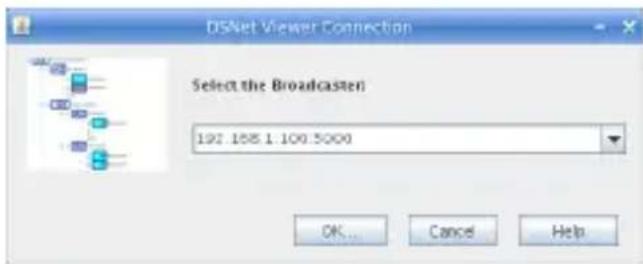
The default IP address is: 192.168.1.100:500
- The next dialog screen will prompt for the login user name and 3. password.
Default user name: superuser
Default password: superu

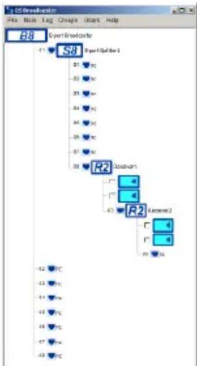
- Once logged into the system, the 4. main window will appear. For a first time setup, have the DSNet Manager scan the network by clicking on the "Menu" option, followed by "Rescan Network". This will attempt to detect all DS128 and DSRXL units currently available on this network.
flowchart
graph TD
    A["Event handlers"] --> B["1"]
    B --> C["S8"]
    C --> D["21"]
    C --> E["33"]
    C --> F["34"]
    C --> G["35"]
    C --> H["36"]
    C --> I["R2"]
    I --> J["43"]
    I --> K["R2 (Temperature)"]
    K --> L["70"]
    K --> M["92"]
    style A fill:#f9f,stroke:#333
    style B fill:#ccf,stroke:#333
    style C fill:#cfc,stroke:#333
    style D fill:#fcc,stroke:#333
    style E fill:#cff,stroke:#333
    style F fill:#ffc,stroke:#333
    style G fill:#cfc,stroke:#333
    style H fill:#fcc,stroke:#333
    style I fill:#cfc,stroke:#333
    style J fill:#fcc,stroke:#333
    style K fill:#cfc,stroke:#333
    style L fill:#fcc,stroke:#333
    style M fill:#cfc,stroke:#333
B8 indicates the DS128 broadcaster unit. The default label "8-Port Broadcaster" can be edited through the software.
R2 indicates the DSRXL receiver units. The default label can be edited through the software. This indicates a connected display device and speakers. The default label can be edited through the software.
Indicates an available port on the DS128 transmitter. "NC" indicates a port with no Receiver unit connected to it.
File
- Save Settings to File: save all settings to a file as backup.
- Restore Settings to File:• use a previously saved configuration file to restore configuration settings.
- Restore Factory Settings: restore the DSNet system to the factory default settings.
- Upgrade Software: upgrade the Broadcaster software.
- Save User Name and Password:• Save the user name and password login, so as not to be prompted again.
- close the DSNet Manager window
Main
- TCP/IP Settings:• configure the TCP/IP settings such as Host Name, Domain Name, IP address, TCP port, network mask, Gateway, DNS, etc.. DHCP mode can also be enabled.
- Date and Time: Set the current date and time. You can sync the Broadcaster's time with the computer time and specify two NTP time servers to synchronize with.
- Rescan Network (F5):• Redetects all hardware on the network.
- Update Receivers and Splitters:• Update the firmware on the Receivers using the resident software/firmware on the Broadcaster.
- Default Network Tree:• Clears all the monitor listings and resets all of the labels to their default values, then proceeds to do a network rescan.
- Redraw Network Tree (F6):• Refresh the main window view.
Log
- Log (F7):• Will record the client access IP and also the important system messages and error messages.
Groups
- New Group: Sets up a new Group of Monitors. To join monitors to a group, you need first checkmark them in the main window.
- List of Groups: Gives a listing of all Groups available.
- Send Command to Checked Monitors:• Send commands such as Video ON/OFF, Audio ON/OFF and also the audio volume adjustment command to the Monitor itself via RS-232 interface. Also you can set the serial connection parameters on the Receiver side.
Users
- New User:• Set up a new user account.
- Edit User:• Edit a user account.
DSRXL Video Configuration
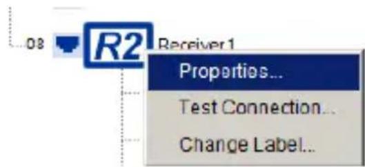
Each DSRXL receiver unit can be individually calibrated for varying physical and environmental conditions. To access the calibration settings, select the Receiver Unit to adjust and right-click on it to bring up the configuration menu and select "Properties"

- Compensation: adjusts the level of compensation.
• Gain: adjusts video brightness.
Red Shift:• adjusts red level video skew.
Blue Shift:• adjusts green level video skew.
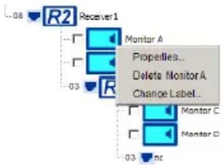
DSRXL Monitor Configuration
Each DSRXL receiver unit has two sets of "Monitor" outputs. These can be individually configured through the DSNet Manager application. To access the Monitor Configuration Menu, right-click on the appropriate Monitor output on the Receiver unit and select the "Properties" option.
Audio Video
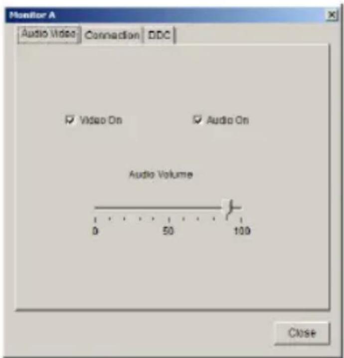
• Video ON: check/uncheck the box to toggle the video stream on the DE-15 VGA connect
- Audio ON: check/uncheck the box to toggle the audio stream on the 3.5mm mini-jack connector.
- Audio Volume:• adjust the slider bar to adjust the audio output on the 3.5mm mini-jack connector.
Connection
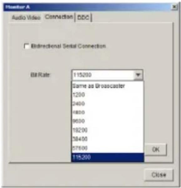
Bidirectional Serial Communication: • check/uncheck for bidirectional serial communication support.
Bit Rate:• set the bit rate (baud) for serial communication on the DB9 serial connector.
DDC
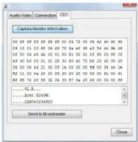
• Capture Monitor Information: • capture DDC information from the connected display device
- Send to Broadcaster:• send the captured DDC information to the Broadcaster unit for use in DDC emulation.
Specifications
| DS128 | |
| Video Format VGA (RGBHV) | |
| Connectors | 8 x RJ452 x RJ45 Ethernet1 x DE-15 VGA female1 x DE-15 VGA male1 x DB9 female1 x DB9 male1 x DC Power |
| LEDs | 8 x Receiver Link2 x RJ45 Link2 x RJ45 10/100 indicator1 x Power |
| Maximum Video Resolution 1600x1200 | |
| Maximum Distance 100m/330ft | |
| Ethernet Speed 10/100Mbps | |
| Serial Protocol RS232 | |
| Power Adapter 5VDC, 2A, center positive | |
| Operating Temperature 0°C ~ 40°C (32°F ~ 104°F) | |
| Storage Temperature -20°C ~ 60°C (-4°F ~ 140°F) | |
| Humidity 0 ~ 90% RH | |
| Dimensions 300.0mm x 160.0mm x 40.0mm | |
| Weight 1400g | |
Specifications
| DSRXL | |
| Video Format VGA (RGBHV) | |
| Connectors | 2 x DE-15 VGA female |
| 2 x DB9 serial male | |
| 2 x RJ45 | |
| 2 x 3.5mm mini-jack | |
| 1 x DC Power | |
| LEDs 1 x Power | |
| Serial Protocol RS232 | |
| Power Adapter 5VDC, 2A, center positive | |
| Operating Temperature 0°C ~ 40°C (32°F ~ 104°F) | |
| Storage Temperature -20°C ~ 60°C (-4°F ~ 140°F) | |
| Humidity 0 ~ 90% RH | |
| Dimensions 130.0mm x 135.0mm x 25.0mm | |
| Weight 700g | |
Technical Support
StarTech.com's lifetime technical support is an integral part of our commitment to provide industry-leading solutions. If you ever need help with your product, visit www.startech.com/support and access our comprehensive selection of online tools, documentation, and downloads.
For the latest drivers/software, please visit www.startech.com/downloads
Warranty Information
This product is backed by a two year warranty.
In addition, StarTech.com warrants its products against defects in materials and workmanship for the periods noted, following the initial date of purchase. During this period, the products may be returned for repair, or replacement with equivalent products at our discretion. The warranty covers parts and labor costs only. StarTech.com does not warrant its products from defects or damages arising from misuse, abuse, alteration, or normal wear and tear.
Limitation of Liability
In no event shall the liability of StarTech.com Ltd. and StarTech.com USA LLP (or their officers, directors, employees or agents) for any damages (whether direct or indirect, special, punitive, incidental, consequential, or otherwise), loss of profits, loss of business, or any pecuniary loss, arising out of or related to the use of the product exceed the actual price paid for the product. Some states do not allow the exclusion or limitation of incidental or consequential damages. If such laws apply, the limitations or exclusions contained in this statement may not apply to you.
Hard-to-find made easy. At StarTech.com, that isn't a slogan. It's a promise.
StarTech.com is your one-stop source for every connectivity part you need. From the latest technology to legacy products — and all the parts that bridge the old and new — we can help you find the parts that connect your solutions.
We make it easy to locate the parts, and we quickly deliver them wherever they need to go. Just talk to one of our tech advisors or visit our website. You'll be connected to the products you need in no time.
Visit www.startech.com for complete information on all StarTech.com products and to access exclusive resources and time-saving tools.
StarTech.com is an ISO 9001 Registered manufacturer of connectivity and technology parts. StarTech.com was founded in 1985 and has operations in the United States, Canada, the United Kingdom and Taiwan servicing a worldwide market.
- VGA over Cat5 Digital Signage Receiver for DS128 with RS232 & Audio
- FCC Compliance Statement
- Use of Trademarks, Registered Trademarks, and other Protected Names and Symbols
- Table of Contents
- Introduction ....1
- Installation 2
- DSRXL Receiver Installation ....3
- How to Use ....4
- DSRXL Video Configuration ....7
- DSRXL Monitor Configuration ....8
- Specifications ....10
- Specifications 11
- Technical Support 12
- Warranty Information 12
- Introduction
- Packaging Contents
- System Requirements
- Installation
- DSRXL Receiver Installation
- Driver Installation
- How to Use
- DSNet Manager
- File
- Main
- Log
- Groups
- Users
- DSRXL Video Configuration
- DSRXL Monitor Configuration
- Connection
- DDC
- Specifications
- Technical Support
- Warranty Information
- Limitation of Liability
Brand : StarTech.com
Model : DSRXL
Category : Audio-Video Distribution