Racetrack RAE4272-RNCY - Table Bretford - Free user manual and instructions
Find the device manual for free Racetrack RAE4272-RNCY Bretford in PDF.

User questions about Racetrack RAE4272-RNCY Bretford
0 question about this device. Answer the ones you know or ask your own.
Ask a new question about this device
Download the instructions for your Table in PDF format for free! Find your manual Racetrack RAE4272-RNCY - Bretford and take your electronic device back in hand. On this page are published all the documents necessary for the use of your device. Racetrack RAE4272-RNCY by Bretford.
USER MANUAL Racetrack RAE4272-RNCY Bretford
WITH POWER/DATA SPHERE (Optional)
OR POWER/POWER SPHERE (Optional)
Assembly Instructions
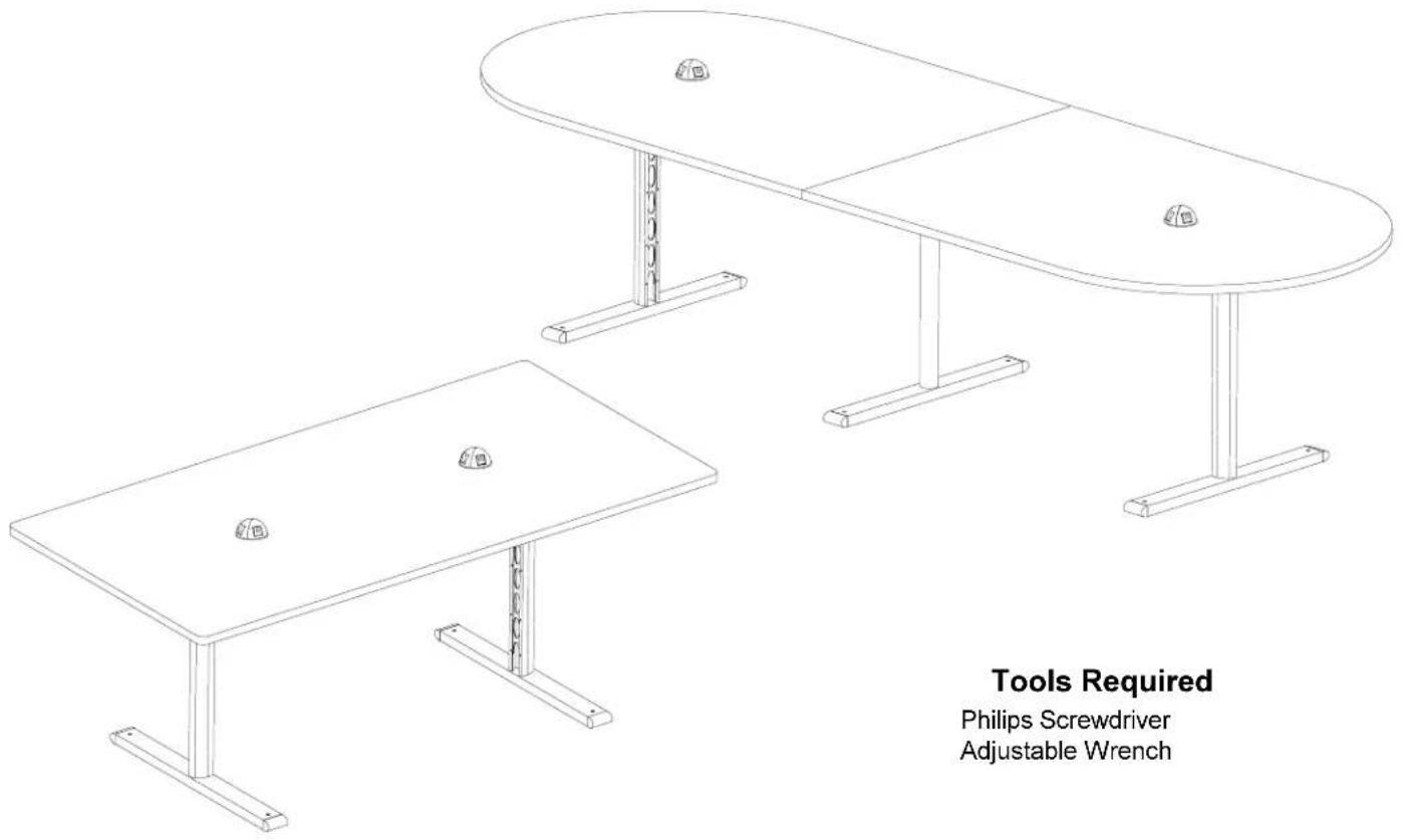
Tools Required
Philips Screwdriver
Adjustable Wrench
PARTS LIST
1 022-1873 Right Leg Assembly
1 022-1871 Left Leg Assembly
1 022-2192 Middle leg Assembly (120" Long Tables)
2 010-2800 34" Long Stiffener (72" Long Table)
2 010-3533 84" Long Stiffener (96" Long Table)
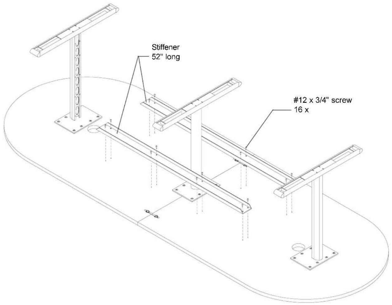
2 010-2464 52" Long Stiffener (120" Long Table)
1 SA5919 - Top
SA5930 (Right & Left for 120" Long Tables)
2 RDOME22 Power/Data Sphere (Optimal)
2 RDOME40 Power/Power Sphere (Optimal)
HARDWARE LIST
24 030-0304 1/4-20 x 5/8" Combo Truss Screws
(Including 16 for 96" & 72" Long Tables)
24 030-0259 #10 x 1/2" Phillips Pan Screws
2 030-0537 Tie-joint (for 120" Long Tables)
16 030-0453 #12 x 3/4" Phillips Truss Head
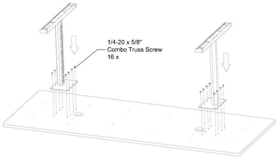
STEP 1
Lay the wood top down with holes facing up as shown. Attach each leg to the wood top with the 1/4-20 x 5/8" screws as shown. Make sure the ellipses on each leg face in as shown. Tighten all screws.

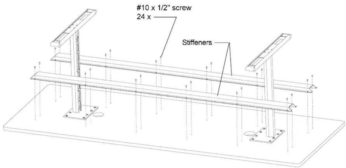
STEP 2
Position the table stiffener over holes and attach in place with the #10 x 1/2" screws as shown. Tighten all screws.
Turn unit over, position and adjust glides to floor.
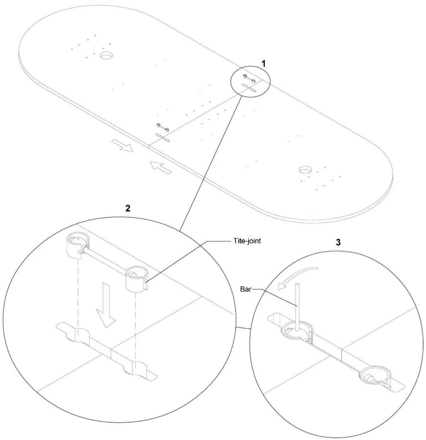
STEP 3 (For 120" Long Tables Only)
- Lay the wood tops down with holes facing up as shown. Slide both halves together until edges are aligned.
- Take two tite-joint connectors and insert them into two slots as shown.
- Using small bar rotate the ball counter-clockwise until both halves of table are securely drawn together.
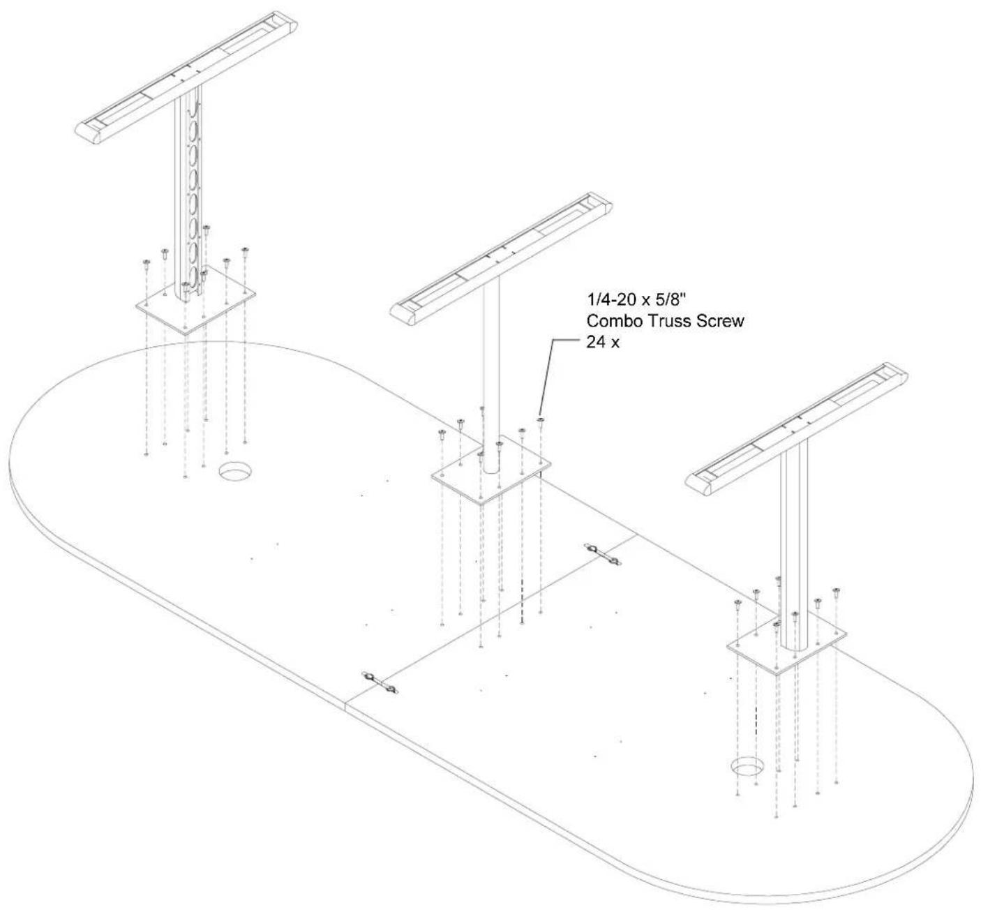
STEP 4
Attach each leg to the wood top with the 1/4-20 x 5/8" screws as shown. Make sure the ellipses on each leg face as shown. Tighten all screws.
STEP 5
Position the table stiffener over holes and attach in place with the #10 x 1/2" screws as shown. Tighten all screws.
Turn unit over, position and adjust glides to floor.
NOTE: See step #6 for installation of optimal power/data sphere or power/power sphere.
STEP 6
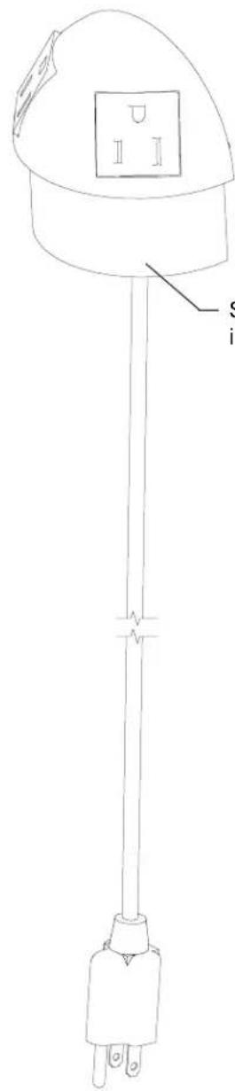
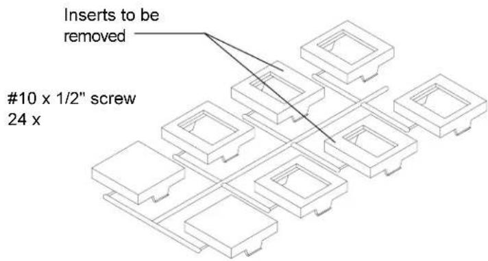
Upon receiving Power/Data Sphere Power half of sphere is ready to install. Other half will require some assembly.
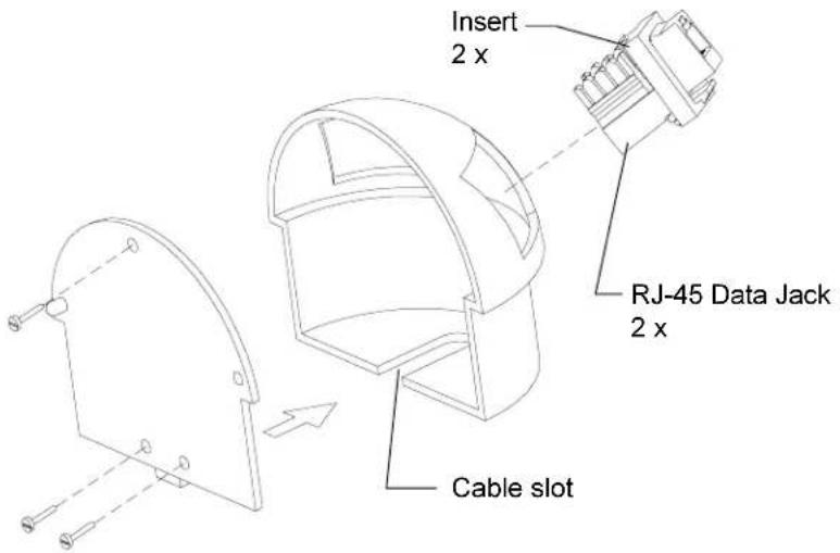
End user will be responsible for wiring Data Jack. After wiring is completed you can take insert & Data Jack and insert into data half as shown until it locks.
With data wire aligned in cable slot, attach rear panel onto data sphere half as shown. Attach the two halves together.
Adapter Kit
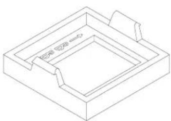
natural_image
Isometric line drawing of a rectangular frame with internal compartments and a small protrusion (no text or symbols)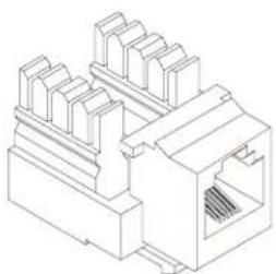
natural_image
Isometric line drawing of a network switch or connector (no text or symbols)Insert RJ-45 Data Jack
STEP 7
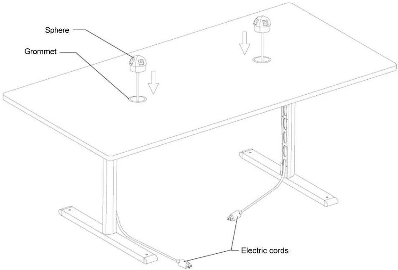
Upon receiving this product the grommets will be already installed in table top. Take electric cords and pull them thru the holes at the top and further thru leg openings.
Install the E-unit into the grommet using mallet (if necessary). The E-unit should be fully seated so entire stem is inside of grommet.
Once your table is in position, it might be necessary to level it. Determine which leg is rocking and using straight blade screwdriver, turn the glide up or down to level.