
Tensioned Dual Masking Electrol - Projection Cabinet DA-LITE - Free user manual and instructions
Find the device manual for free Tensioned Dual Masking Electrol DA-LITE in PDF.

| Product Type | Projection Screen Cabinet with Dual Masking |
| Brand | Da-Lite |
| Model | Tensioned Dual Masking Electrol |
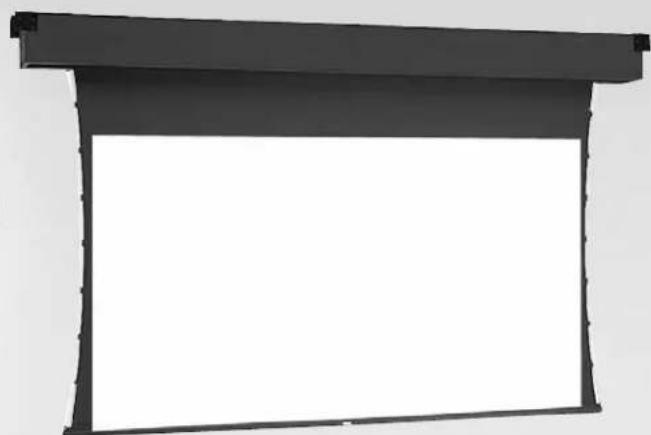
| Screen Surface | Tensioned fabric for flat, wrinkle-free image |
| Masking System | Dual motorized masking surfaces for variable aspect ratio |
| Motor Type | Two sealed motor assemblies (picture and mask) |
| Power Options | 120V AC / 220-240V AC, 50/60 Hz; low voltage control available |
| Duty Cycle | 1 minute operation / 3 minutes off (standard) |
| Limit Switches | Built-in pre-set limit switches for up and down positions |
| Installation | Recessed above ceiling; offset or flush mounting methods |
| Safety Compliance | Complies with NEC, CEC, and CAN/CSA C22.1 |
| Warranty | 1 year limited warranty on materials and workmanship |
| Included Accessories | Mounting brackets, hardware, wiring diagram |
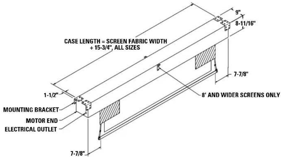
| Screen Width Range | Available in various widths; center support brackets for 8 ft and wider |
| Masking Operation | Mask travels down past viewing surface then steps back to eliminate shadow |
| Manufacturer | Da-Lite Screen Company, Inc., Warsaw, IN USA |
Frequently Asked Questions - Tensioned Dual Masking Electrol DA-LITE
User questions about Tensioned Dual Masking Electrol DA-LITE
0 question about this device. Answer the ones you know or ask your own.
Ask a new question about this device
Download the instructions for your Projection Cabinet in PDF format for free! Find your manual Tensioned Dual Masking Electrol - DA-LITE and take your electronic device back in hand. On this page are published all the documents necessary for the use of your device. Tensioned Dual Masking Electrol by DA-LITE.
USER MANUAL Tensioned Dual Masking Electrol DA-LITE
The Da-Lite Difference.

Instruction Book for
TENSIONED DUAL MASKING ELECTROL®

DA-LITE SCREEN COMPANY, INC.
3100 North Detroit Street
Post Office Box 137
Warsaw, Indiana 46581-0137
Phone: 574-267-8101
800-622-3737
Fax: 574-267-7804
Toll Free Fax: 877-325-4832
www.da-lite.com
e-mail: info@da-lite.com
IMPORTANT SAFETY INSTRUCTIONS
When using your video equipment, basic safety precautions should always be followed, including the following:
- Read and understand all instructions before using.
- Position the cord so that it will not be tripped over, pulled, or contact hot surfaces.
- If an extension cord is necessary, a cord with a current rating at least equal to that of the appliance should be used. Cords rated for less amperage than the appliance may overheat.
- To reduce the risk of electric shock, do not disassemble this appliance. Contact an authorized service dealer when repair work is required. Incorrect reassembly can cause electric shock when the appliance is used subsequently.
- The use of an accessory attachment not recommended by the manufacturer may cause a risk of fire, electric shock, or injury to persons.
SAVE THESE INSTRUCTIONS
PRE-INSTALLATION
- Carefully unpack screen and remove outer wrapping from case.
- Make sure to recheck measurements of screen location before installation.
- Remove center support brackets (on 8' and wider screens only), reverse brackets and reinstall flush with the top of the box.
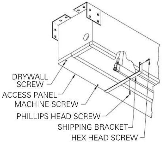
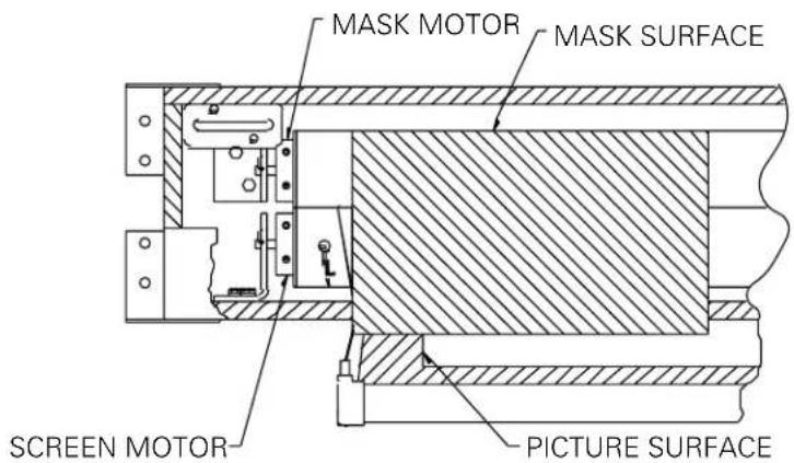
FIGURE 1 FIGURE 2
INSTALLATION
- Install screen by raising unit into position between joists at one end only. Install one lag screw in each mounting bracket.
- Level unit lengthwise with a carpenter's level and plumb level. Secure opposite end.

CAUTION! Do not seal in until screen has been secured in position and properly tested for satisfactory operation.
- Carefully remove three shipping brackets by removing six hex head screws from case and three phillips head screws from aluminum slat. Use a phillips screwdriver, a hex socket and a ratchet. Slat should move freely (Fig. 1).
- Detach access panel by removing screws (Fig. 1).
- Remove junction box cover plate.
- Install electric hook up that applies to your unit. Make sure to review your electrical installation checklist and wiring diagram (included) for either 120 volt switch, 220/240 volt switch or low voltage control.
NOTE: Must be installed in accordance with the requirements of the Local Building Codes, the Canadian Electrical Code (CEC), CAN/CSA C22.1 and the National Electric Code (NEC), NFPA 70.

CAUTION! DO NOT CUT TAPE ON FABRIC WITH A KNIFE OR ANY SHARP TOOL. REMOVE BY HAND.
- Carefully remove two wood boards securing mask surface to case.
- Test installation by carefully running picture and mask surfaces up and down several times. Be prepared to stop screen. Standard Duty Cycle: 1 MIN. ON / 3 MIN. OFF.
NOTE: When rolled down, the picture surface should wrap fully around the roller. No part of the roller should be exposed. Picture and mask surfaces will automatically stop in the down position.
The mask will start down off the front of the roller, travel completely down past the bottom of the viewing surface, then "step back" against the viewing surface to eliminate shadowing by rolling up the back side of the roller. Do not adjust the limits to change this feature.
- Run the picture and mask surfaces upward. When the picture and mask surfaces are fully up the limit switches (in the motors) are tripped and the motors shut off.
- Check for satisfactory condition by operating screen a few times. Reinstall access panel.
SCREEN ADJUSTMENT

NATION! THE MASK SHOULD NOT BE FIELD ADJUSTED FOR MORE OR LESS DROP.

TACT DA-LITE AT 800-622-3737 OR 574-267-8101 IF SCREEN MOTOR NEEDS ADJUSTMENT.
TENSIONED DUAL MASKING ELECTROL® INSTRUCTIONS
TENSIONED DUAL MASKING ELECTROL® INSTRUCTIONS
220V DUAL MOTOR CONTROL

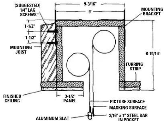
SUGGESTED METHODS OF INSTALLATION
METHOD A METHOD B

Offset mounting, recessed above ceiling. For plaster, dry wall, tile or paneling. Bottom of case painted same finish as ceiling.
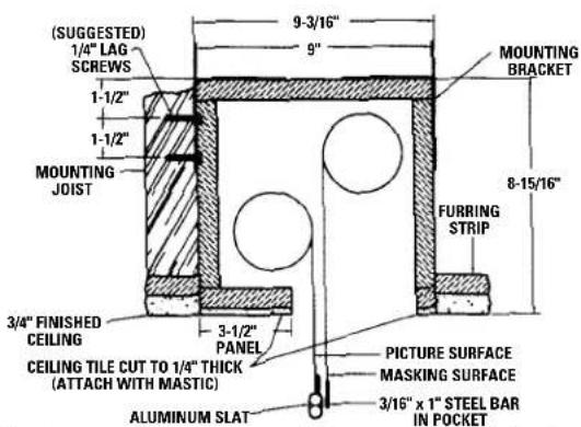
Offset mounting, recessed above ceiling. May be adapted for 3/4" ceiling, but cut to 1/4" thick under screen case and panel.
NOTE:
MUST MARK HOLE LOCATION OF SCREWS IN 3-1/2" PANEL FOR REMOVAL, IF COVERING WITH TILE.
METHOD C METHOD D
Offset mounting, recessed above ceiling. May be adapted for 1/4" paneling for ceiling.
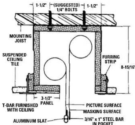
Flush mounting, recessed above ceiling. For use with dropped ceiling. May also be adapted for use with acoustical or other ceiling 3/4" thick but cut to 1/4" thick under screen case and panel.
TENSIONED DUAL MASKING ELECTROL® INSTRUCTIONS
TROUBLESHOOTING
Visit www.da-lite.com/products/tutorials.php to find installation and troubleshooting tutorials. You will also find a link to Live Chat for interactive support and you can contact us by email at info@da-lite.com or by phone at (800) 622-3737 or (574) 267-8101 with any troubleshooting questions.
| SYMPTOM | CAUSE | SOLUTION |
| 1. Screen will not operate.Motor doesnothum. | (a) Incorrect line voltage.(b)Blownfuse.(c) Tripped circuit breaker.(d) No power to operating switch or junction.Power at junction box(e) Thermal overload tripped.(f) Broken wire in the“down”or“up”position.(g) Defective motor, limit switch or capacitor.(h) Capacitor burned out. | (a) Verify 115-125V (or 220-240V). If insufficient voltage, rewire incoming electric line.(b)Replacefuse.(c) Reset circuit breaker.(d) Check above. Tighten all loose wire connections. Correct any improper connections.“Down” PositionCheck for power across black and white leads.“Up” PositionCheck for power across red and white leads.(e) Let motor cool down for 15 minutes. Try again.(f) Check for continuity. Cut off old splice and reconnect.(g) Replace motor assembly.NOTE: Motor is a sealed assembly.(h) Replace motor assembly. |
| 2. Incorrect stopping position in downward direction. | (a) “Down” limit switch out of adjustment | (a) Seeinstallationinstructions. |
| 3. Incorrect stopping position in upward direction. | (a) “Up” limit switch out of adjustment | (a) Adjust“up” limit switch. See installation instructions |
| 4. Noise.NOTE: Screen will operate with a low pitched hum. | (a) Gear Noise. | (a) Replace motor assembly. |
| 5. Coasting. | (a) Defectivebrake. | (a) Replace motor assembly. |
LIMITED ONE YEAR WARRANTY ON DA-LITE PRESENTATION PRODUCTS
Da-Lite Screen Company, Inc. warrants its products to the original purchaser only, to be free from defects in materials and workmanship for a period of one (1) year from the date of purchase by the original purchaser provided they are properly operated according to Da-Lite's instructions and are not damaged due to improper handling or treatment after shipment from the factory.
This warranty does not apply to equipment showing evidence of misuse, abuse or accidental damage, or which has been tampered with or repaired by a person other than authorized Da-Lite personnel.
Da-Lite's sole obligation under this warranty shall be to repair or to replace (at Da-Lite's option) the defective part of the merchandise. Returns for service should be made to your Da-Lite dealer. If it is necessary for the dealer to return the screen or part to Da-Lite, transportation expenses to and from Da-Lite are payable by the purchaser and Da-Lite is not responsible for damage in shipment. To protect yourself against damage or loss in transit, insure the product and prepay all transportation expenses.
THIS WARRANTY IS IN LIEU OF ALL OTHER WARRANTIES, EXPRESS OR IMPLIED, INCLUDING WARRANTIES AS TO FITNESS FOR USE AND MERCHANTABILITY. Any implied warranties of fitness for use, or merchantability, that may be mandated by statute or rule of law are limited to the one (1) year warranty period. This warranty gives you specific legal rights, and you may also have other rights, which vary from state-to-state. NO LIABILITY IS ASSUMED FOR EXPENSES OR DAMAGES RESULTING FROM INTERRUPTION IN OPERATION OF EQUIPMENT, OR FOR INCIDENTAL, DIRECT, OR CONSEQUENTIAL DAMAGES OF ANY NATURE.
In the event that there is a defect in materials or workmanship of a Da-Lite product, you may contact our Sales Partners at PO Box 137, Warsaw, IN 46581-0137, (574) 267-8101, (800) 622-3737.
IMPORTANT: THIS WARRANTY SHALL NOT BE VALID AND DA-LITE SHALL NOT BE BOUND BY THIS WARRANTY IF THE PRODUCT IS NOT OPERATED IN ACCORDANCE WITH DA-LITE'S WRITTEN INSTRUCTIONS.
Keep your sales receipt to prove the date of purchase and your original ownership.


- THE DA-LITE DIFFERENCE
- IMPORTANT SAFETY INSTRUCTIONS
- SAVE THESE INSTRUCTIONS
- PRE-INSTALLATION
- INSTALLATION
- SCREEN ADJUSTMENT
- TENSIONED DUAL MASKING ELECTROL® INSTRUCTIONS
- SUGGESTED METHODS OF INSTALLATION
- NOTE
- MUST MARK HOLE LOCATION OF SCREWS IN 3-1/2" PANEL FOR REMOVAL, IF COVERING WITH TILE
- TROUBLESHOOTING
- LIMITED ONE YEAR WARRANTY ON DA-LITE PRESENTATION PRODUCTS
Brand : DA-LITE
Model : Tensioned Dual Masking Electrol
Category : Projection Cabinet