VSX 12400 BDL - Firewall Check Point - Free user manual and instructions
Find the device manual for free VSX 12400 BDL Check Point in PDF.

User questions about VSX 12400 BDL Check Point
0 question about this device. Answer the ones you know or ask your own.
Ask a new question about this device
Download the instructions for your Firewall in PDF format for free! Find your manual VSX 12400 BDL - Check Point and take your electronic device back in hand. On this page are published all the documents necessary for the use of your device. VSX 12400 BDL by Check Point.
USER MANUAL VSX 12400 BDL Check Point
Check Point 12000 VSX
R67.10
Getting Started Guide

natural_image
Software blade logo with colorful vertical bars on white background, no text or symbols on the graphic itself24 November 2011
© 2011 Check Point Software Technologies Ltd.
All rights reserved. This product and related documentation are protected by copyright and distributed under licensing restricting their use, copying, distribution, and decompilation. No part of this product or related documentation may be reproduced in any form or by any means without prior written authorization of Check Point. While every precaution has been taken in the preparation of this book, Check Point assumes no responsibility for errors or omissions. This publication and features described herein are subject to change without notice.
RESTRICTED RIGHTS LEGEND:
Use, duplication, or disclosure by the government is subject to restrictions as set forth in subparagraph (c)(1)(ii) of the Rights in Technical Data and Computer Software clause at DFARS 252.227-7013 and FAR 52.227-19.
TRADEMARKS:
Refer to the Copyright page (http://www.checkpoint.com/copyright.html) for a list of our trademarks.
Refer to the Third Party copyright notices (http://www.checkpoint.com/3rd_party_copyright.html) for a list of relevant copyrights and third-party licenses.
Important Information
Latest Software
We recommend that you install the most recent software release to stay up-to-date with the latest functional improvements, stability fixes, security enhancements and protection against new and evolving attacks.
Latest Documentation
The latest version of this document is at:
http://supportcontent.checkpoint.com/documentation_download?ID=12528
For additional technical information, visit the Check Point Support Center
(http://supportcenter.checkpoint.com).
Revision History
| Date | Description |
| 24 November 2011 | Added 12400 VSX appliance. |
| 9 October 2011 | First release of this document. |
Feedback
Check Point is engaged in a continuous effort to improve its documentation.
Please help us by sending your comments
(mailto:cp_techpub_feedback@checkpoint.com?subject=Feedback on Check Point 12000 VSX R67.10
Getting Started Guide).
Safety, Environmental, and Electronic Emissions Notices
Read the following warnings before setting up or using the appliance.

Warning - Do not block air vents. A minimum 1/2-inch clearance is required.

Warning - This appliance does not contain any user-serviceable parts. Do not remove any covers or attempt to gain access to the inside of the product. Opening the device or modifying it in any way has the risk of personal injury and will void your warranty. The following instructions are for trained service personnel only.
To prevent damage to any system board, it is important to handle it with care. The following measures are generally sufficient to protect your equipment from static electricity discharge:
- When handling the board, to use a grounded wrist strap designed for static discharge elimination.
- Touch a grounded metal object before removing the board from the antistatic bag.
- Handle the board by its edges only. Do not touch its components, peripheral chips, memory modules or gold contacts.
- When handling processor chips or memory modules, avoid touching their pins or gold edge fingers.
- Restore the communications appliance system board and peripherals back into the antistatic bag when they are not in use or not installed in the chassis. Some circuitry on the system board can continue operating even though the power is switched off.
- Under no circumstances should the lithium battery cell used to power the real-time clock be allowed to short. The battery cell may heat up under these conditions and present a burn hazard.

Warning - DANGER OF EXPLOSION IF BATTERY IS INCORRECTLY REPLACED. REPLACE ONLY WITH SAME OR EQUIVALENT TYPE RECOMMENDED BY THE MANUFACTURER. DISCARD USED BATTERIES ACCORDING TO THE MANUFACTURER'S INSTRUCTIONS.
- Disconnect the system board power supply from its power source before you connect or disconnect cables or install or remove any system board components. Failure to do this can result in personnel injury or equipment damage.
- Avoid short-circuiting the lithium battery; this can cause it to superheat and cause burns if touched.
- Do not operate the processor without a thermal solution. Damage to the processor can occur in seconds.
• Class 1 Laser Product Warning
Rack Mount Instructions
The following or similar rack-mount instructions are included with the installation instructions:
- Elevated Operating Ambient - If installed in a closed or multi-unit rack assembly, the operating ambient temperature of the rack environment may be greater than room ambient. Therefore, consideration should be given to installing the equipment in an environment compatible with the maximum ambient temperature specified by the manufacturer.
- Reduced Air Flow - Installation of the equipment in a rack should be such that the amount of air flow required for safe operation of the equipment is not compromised.
-
Mechanical Loading - Mounting of the equipment in the rack should be such that a hazardous condition is not achieved due to uneven mechanical loading.
-
Circuit Overloading - Consideration should be given to the connection of the equipment to the supply circuit and the effect that overloading of the circuits might have on over current protection and supply wiring. Appropriate consideration of equipment nameplate ratings should be used when addressing this concern.
- Reliable Earthing - Reliable earthing of rack-mounted equipment should be maintained. Particular attention should be given to supply connections other than direct connections to the branch circuit (e.g. use of power strips).
For California:
Perchlorate Material - special handling may apply. See http://www.dtsc.ca.gov/hazardouswaste/perchlorate
The foregoing notice is provided in accordance with California Code of Regulations Title 22, Division 4.5, Chapter 33. Best Management Practices for Perchlorate Materials. This product, part, or both may include a lithium manganese dioxide battery which contains a perchlorate substance.
Proposition 65 Chemical
Chemicals identified by the State of California, pursuant to the requirements of the California Safe Drinking Water and Toxic Enforcement Act of 1986, California Health & Safety Code s. 25249.5, et seq. ("Proposition 65"), that is "known to the State to cause cancer or reproductive toxicity" (see http://www.calepa.ca.gov)
WARNING:
Handling the cord on this product will expose you to lead, a chemical known to the State of California to cause cancer, and birth defects or other reproductive harm. Wash hands after handling.
Federal Communications Commission (FCC) Statement:
For a Class A digital device or peripheral
Note: This equipment has been tested and found to comply with the limits for a Class A digital device, pursuant to Part 15 of the FCC Rules. These limits are designed to provide reasonable protection against harmful interference when the equipment is operated in a commercial environment. This equipment generates, uses, and can radiate radio frequency energy and, if not installed and used in accordance with the instruction manual, may cause harmful interference to radio communications. Operation of this equipment in a residential area is likely to cause harmful interference in which case the user will be required to correct the interference at his own expense.
For a Class B digital device or peripheral
NOTE: This equipment has been tested and found to comply with the limits for a Class B digital device, pursuant to Part 15 of the FCC Rules. These limits are designed to provide reasonable protection against harmful interference in a residential installation. This equipment generates, uses and can radiate radio frequency energy and, if not installed and used in accordance with the instructions, may cause harmful interference to radio communications. However, there is no guarantee that interference will not occur in a particular installation. If this equipment does cause harmful interference to radio or television reception, which can be determined by turning the equipment off and on, the user is encouraged to try to correct the interference by one or more of the following measures:
- Reorient or relocate the receiving antenna.
- Increase the separation between the equipment and receiver.
- Connect the equipment into an outlet on a circuit different from that to which the receiver is connected.
- Consult the dealer or an experienced radio/TV technician for help.
Information to user:
The user's manual or instruction manual for an intentional or unintentional radiator shall caution the user that changes or modifications not expressly approved by the party responsible for compliance could void the user's authority to operate the equipment. In cases where the manual is provided only in a form other than paper, such as on a computer disk or over the Internet, the information required by this section may be included in the manual in that alternative form, provided the user can reasonably be expected to have the capability to access information in that form.
Canadian Department Compliance Statement:
Japan Compliance Statement:
Class A
This product is herewith confirmed to comply with the requirements set out in the Council Directive on the Approximation of the Laws of the Member States relating to Electromagnetic Compatibility Directive (2004/108/EC). For the evaluation regarding the Electromagnetic Compatibility (2004/108/EC)
This product is in conformity with Low Voltage Directive 2006/95/EC, and complies with the requirements in the Council Directive 2006/95/EC relating to electrical equipment designed for use within certain voltage limits and the Amendment Directive 93/68/EEC.
natural_image
Symbol of a trash bin crossed with two diagonal lines, representing no waste or discharge (no text or labels)Product Disposal
This symbol on the product or on its packaging indicates that this product must not be disposed of with your other household waste. Instead, it is your responsibility to dispose of your waste equipment by handing it over to a designated collection point for the recycling of waste electrical and electronic equipment. The separate collection and recycling of your waste equipment at the time of disposal will help to conserve natural resources and ensure that it is recycled in a manner that protects human health and the environment. For more information about where you can drop off your waste equipment for recycling, please contact your local city office or your household waste disposal service.
Important Information....3
Safety, Environmental, and Electronic Emissions Notices......4
Introduction......9
Welcome 9
Check Point 12000 VSX Overview 9
VSX Overview 9
Important Solutions....10
Shipping Carton Contents....10
Rack Mounting....11
Rack Mounting Hardware and Tools....11
Rack Mounting Check Point 12200 VSX....12
Attaching the Ear Mount Brackets to the Appliance 12
Attaching the Rail Plates....12
Attaching the Appliance Rails to the Appliance....13
Installing the Appliance in the Rack 14
Rack Mounting Check Point 12400 and 12600 VSX....15
Attaching the Ear Mount Brackets to the Appliance ....15
Attaching the Rail Plates....15
Attaching the Appliance Rails to the Appliance 16
Installing the Appliance in the Rack 17
Configuring Check Point 12000 VSX....18
Powering On....18
Initial Configuration....19
Logging in for the First Time ....19
Configuring the Management Interface....20
Setting Network and Time/Date Properties 21
Selecting Cluster Options ......21
Completing the Configuration....21
Confirming the Build Numbers....22
Check Point 12000 VSX Hardware....23
Front Panel Components....23
Check Point 12200 VSX Front Panel 23
Check Point 12400 VSX Front Panel 24
Check Point 12600 VSX Front Panel 25
Rear Panel Components 27
Check Point 12200 VSX Rear Panel....27
Check Point 12400 and 12600 VSX Rear Panel....27
Using the LCD Panel....28
Customer Replaceable Parts 29
Replacing Power Supplies....29
Removing Power Supplies....30
Installing Power Supplies....30
Replacing Expansion Line Cards....30
Removing Expansion Line Cards....31
Installing Expansion Line Cards....31
Replacing Hard Disk Drives on Check Point 12200 VSX....32
Removing a Hard Disk Drive....32
Installing a Hard Disk Drive....32
Replacing Hard Disk Drives on Check Point 12400 and 12600 VSX ....33
Removing a Hard Disk Drive....33
Installing a Hard Disk Drive....33
VSX Appliance Recovery....34
Registration and Support....35
Registration 35
Support....35
Where To From Here? 35
Compliance Information....36
Declaration of Conformity 36
Introduction
In This Chapter
Welcome 9
Check Point 12000 VSX Overview 9
VSX Overview 9
Important Solutions 10
Shipping Carton Contents 10
Welcome
Thank you for choosing Check Point 12000 VSX. We hope that you will be satisfied with this system and our support services. Check Point products provide your business with the most up to date and secure solutions available today.
Check Point also delivers worldwide technical services including educational, professional and support services through a network of Authorized Training Centers, Certified Support Partners and Check Point technical support personnel to ensure that you get the most out of your security investment.
For additional information on the Internet Security Product Suite and other security solutions, refer to the Check Point Web site (http://www.checkpoint.com). For additional technical information about Check Point products, consult the Check Point Support Center (http://supportcenter.checkpoint.com).
Welcome to the Check Point family. We look forward to meeting all of your current and future network, application and management security needs.
Check Point 12000 VSX Overview
The family of Check Point 12000 VSX appliances enables organizations to maximize security in high-performance environments such as large campuses or data centers. Combining integrated firewall, IPSec VPN, and intrusion prevention with advanced acceleration technologies, Check Point 12000 VSX appliances deliver a high-performance security platform capable of blocking application layer threats. Even as new threats appear, Check Point 12000 VSX appliances maintain or increase performance while protecting the network against attacks.
VSX Overview
The VSX (Virtual System eXtension) appliance is a security and VPN solution, designed to meet the demands of large-scale environments. Based on the proven security of Security Gateway, VSX provides comprehensive protection for multiple networks or VLANs within complex infrastructures. It securely connects them to shared resources such as the Internet and DMZs, and allows them to safely interact with each other. VSX is supported by IPS, which provide up-to-date preemptive security.
VSX incorporates the same patented Stateful Inspection and Application Intelligence technologies used in the Check Point Security Gateway product line. It runs on high speed platforms (known as VSX Gateways) to deliver superior performance in high-bandwidth environments. Administrators manage VSX via a Security Management server or a Multi-Domain Security Management, delivering a unified management architecture that supports enterprises and service providers.
A VSX gateway contains a complete set of virtual devices that function as physical network components, such as Security Gateways, routers, switches, interfaces, and even network cables. Centrally managed, and incorporating key network resources internally, VSX allows businesses to deploy comprehensive firewall and VPN functionality, while reducing hardware investment and improving efficiency.
Key Features:
• Combines Virtual Firewall, VPN, and IPS
• Consolidates Security Gateways Onto a Single Hardware Platform
- Includes Virtualized Networking Components- Virtual routers, Virtual switches & Virtual cabling
• Wire-Speed Security for Gigabit Networks
• High Availability with Linear Growth Clustering
• Bridge Mode Support for Transparent Internal Firewalls
• Flexible Virtual Network Design
- IPS Services Updates
- URL Filtering
This document provides:
- A brief overview of essential VSX concepts and features
- A step by step guide to getting VSX up and running

Note - Screen shots in this guide may apply only to the highest model to which this guide applies.
Important Solutions
- For more information about R67.10 VSX, go to the Check Point R67.10 VSX Home Page (http://supportcontent.checkpoint.com/solutions?id=sk65291).
- For a list of open issues, see the Known Limitations (http://supportcontent.checkpoint.com/solutions?id=sk65292).
- For a list of closed issues, see the Resolved Issues (http://supportcontent.checkpoint.com/solutions?id=sk65293).
Shipping Carton Contents
This section describes the contents of the shipping carton.
| Item | Description |
| Appliance | Check Point 12200, 12400, or 12600 VSX appliance |
| Rack Mounting Accessories | Hardware mounting kit |
| Cables | Power cable (12200 VSX appliance)2 Power cables (12400 and 12600 VSX appliance)1 Standard RJ-45 network cable1 Serial console cable |
| Documentation | Getting Started GuideUser license agreement |
Rack Mounting
This chapter describes how to mount the appliance in a rack.

Important - Two people are required to install the appliance in a rack in order to prevent any possible damage.
In This Chapter
Rack Mounting Hardware and Tools 11
Rack Mounting Check Point 12200 VSX 12
Rack Mounting Check Point 12400 and 12600 VSX 15
Rack Mounting Hardware and Tools
You must install rack mounting hardware on the appliance before you can mount it in a rack. This table describes the rack mounting hardware.

Note - Screws to attach the ear mount brackets and rail plates to the rack are not included.
| Hardware Description | Qty. | Use |
| Ear mount bracket | 2 | Attaches to the appliance front panel. Both ear mount brackets are identical. |
| Ear mount screws | 6 | Secures the ear mount brackets to the appliance front panel. |
| Appliance rail | 2 | Attaches to the appliance. Both rails are identical. |
| Rail plates | 2 | Attaches to the appliance rails. Both plates are identical. |
| Appliance rail screws | 14 | Secures the rail plates to the appliance rails and the rails to the appliance. |
Rack Mounting Tools
Philips screwdriver. A magnetic head is recommended to hold screws in place and retrieve dropped screws. A powered screwdriver is also useful.
Rack Mounting Check Point 12200 VSX Attaching the Ear Mount Brackets to the Appliance
Attach the two ear mount brackets to the front of the appliance.
natural_image
Line drawing of a server rack unit with ports, buttons, and ventilation slots (no text or symbols)
Note - The ear mount screws have 5 mm heads.
To attach the ear mount brackets to the appliance:
-
Attach the appliance ear bracket to one side of the appliance using three ear mount screws.
-
Do step 1 again for the other side of the appliance.
Attaching the Rail Plates
Attach the rail plates to the appliance rails to connect the appliance to the rear vertical rails of the rack.
| Item | Description |
| 1 | Appliance rail |
| 2 | Rail plate |

Note - The appliance rail screws have 8 mm heads.
To attach the rail plates:
- Attach a rail plate to an appliance rail using two appliance rail screws.
- Do step 1 again for the other rail plate and appliance rail.
This figure shows the assembled rail plate and appliance rail.
natural_image
Technical line drawing of a metal bracket with mounting holes and mounting holes (no text or symbols)Attaching the Appliance Rails to the Appliance
Attach the appliance rails to the sides of the appliance. Position the rail plates to connect the appliance rails to the rear of the rack.

Note - The appliance rail screws have 8 mm heads.
To attach the appliance rails:
- Set the appliance rail on the side of the appliance. The ridges on the appliance rails point to the appliance. This diagram shows the appliance rail and rail plate positioned correctly:
natural_image
Technical line drawing of a computer monitor with ventilation slots and a rack (no text or symbols)- Attach the appliance rails to the appliance using three appliance rail screws.
- Do steps 1 and two again for the other side of the appliance.
Installing the Appliance in the Rack
Install the appliance in the rack. It may be necessary to adjust the appliance rails to secure the appliance to the rack.
natural_image
Line drawing of a server rack unit with ventilation slots and mounting bracket (no text or symbols)
Important - Two people are required to install the appliance in a rack in order to prevent personal injury or damage to the appliance.
To install the appliance in the rack:
- Attach the ear mount brackets to the front of the rack.
- Attach the rail plates to the rear of the rack.
- Confirm that the appliance is stable and secure in the rack.
Rack Mounting Check Point 12400 and 12600 VSX
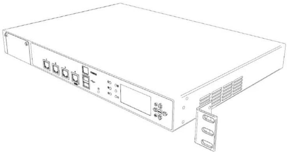
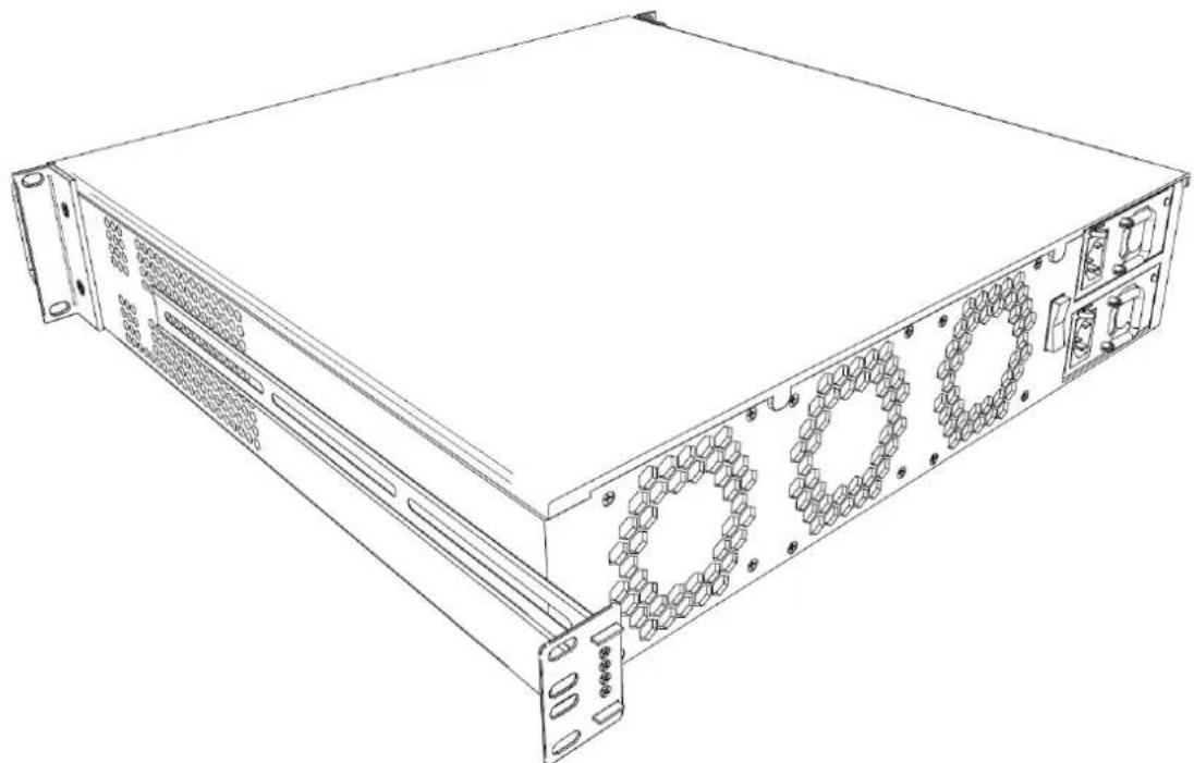
Attaching the Ear Mount Brackets to the Appliance
Attach the two ear mount brackets to the front of the appliance.
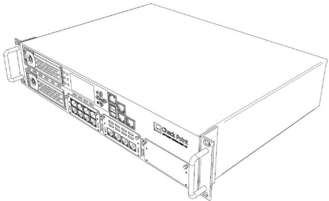
natural_image
Line drawing of a server rack unit with labeled ports and connectors (no text or symbols beyond 'Check Point' label)To attach the ear mount brackets to the appliance:
- Attach the appliance ear bracket to one side of the appliance using three ear mount screws.
- Do step 1 again for the other side of the appliance.
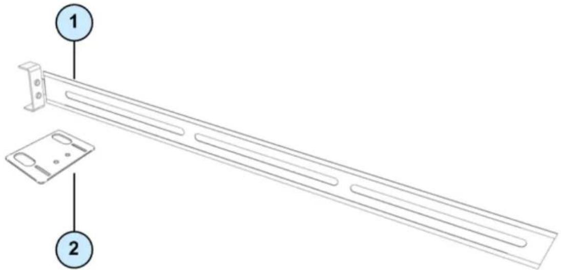
Attaching the Rail Plates
Attach the rail plates to the appliance rails to attach the appliance to the rear vertical rails of the rack.
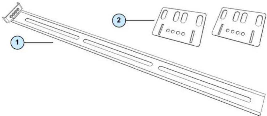
| Item | Description |
| 1 | Appliance rail |
| 2 | Rail plates |
To attach the rail plates:
- Attach a rail plate to an appliance rail using four appliance rail screws.
- Do step 1 again for the other rail plate and appliance rail.
This figure shows the assembled rail plate and appliance rail.
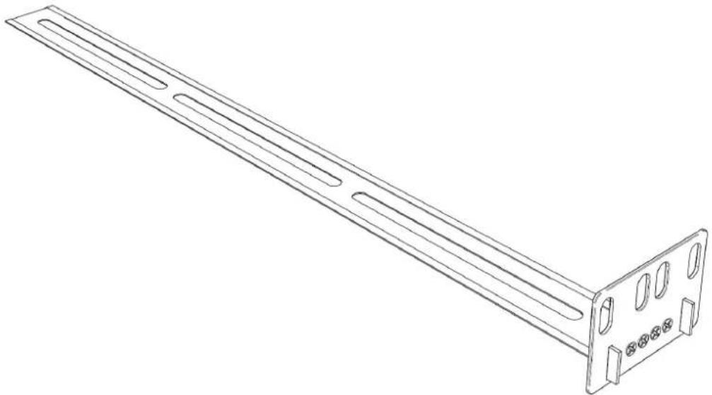
natural_image
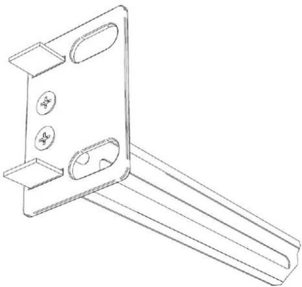
Line drawing of a metal shelf support structure with mounting holes and mounting brackets (no text or symbols)Attaching the Appliance Rails to the Appliance
Attach the appliance rails to the sides of the appliance. The rail plates are positioned to connect the appliance rails to the rear of the rack.
To attach the appliance rails:
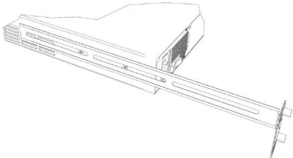
- Set the appliance rail on the side of the appliance. The ridges on the appliance rails point to the appliance. This diagram shows the appliance rail and rail plate positioned correctly:
natural_image
Line drawing of a server rack unit with multiple drive bays and ventilation slots (no text or labels)- Attach the appliance rails to the appliance using three appliance rail screws.
- Do steps 1 and 2 again for the other side of the appliance.
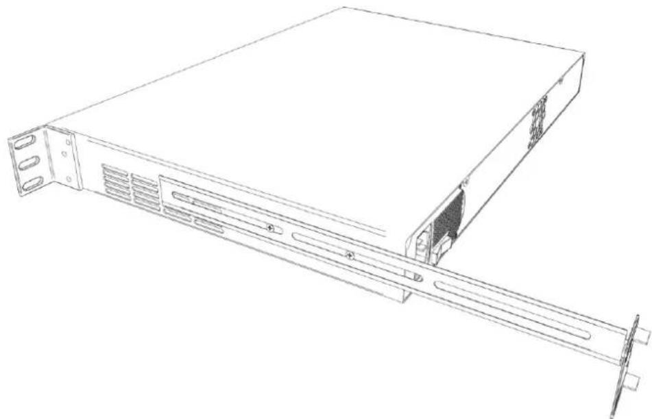
Installing the Appliance in the Rack
Install the appliance in the rack. It may be necessary to adjust the appliance rails to secure the appliance to the rack.

Important - Two people are required to install the appliance in a rack in order to prevent personal injury or damage to the appliance.
To install the appliance in the rack:
- Attach the ear mount brackets to the front of the rack.
- Attach the rail plates to the rear of the rack.
- Confirm that the appliance is stable and secure in the rack.
Configuring Check Point 12000 VSX
The workflow for configuring Check Point 12000 VSX is:
- Mount the Check Point 12000 VSX in the rack.
- Connect the cables and power on.
- Use the First Time Wizard to configure the appliance.
- Configure VSX in SmartDashboard and install a policy.

Note - Check Point 12000 VSX must be managed by a Security Management Server or Multi-Domain Security Management as described in the VSX NGX R67 Administration Guide
(http://supportcontent.checkpoint.com/documentation_download?ID=10165). Security Management Server is not installed locally on Check Point 12000 VSX.
In This Chapter
Powering On 18
Initial Configuration 19
Confirming the Build Numbers 22
Powering On
To power on Check Point 12000 VSX:
- Connect the power cable.
- On the back panel, turn on the Power button to start the appliance.

Note -When a power supply fails or is not connected to the outlet, an alarm sounds continuously. If you hear the alarm, replace the faulty power supply immediately, and connect the new unit to an A/C outlet.
- Wait for the appliance to initialize and boot. The status of the appliance appears on the LCD screen:
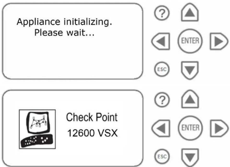
The appliance is ready to use when the model number is displayed.
Initial Configuration
Logging in for the First Time
Check Point 12000 VSX includes a First Time Wizard to help you configure the initial settings for the appliance.
To log in and start the First Time Wizard:
- Connect to the appliance's Serial console using the RJ45/D subminiature cable.
- Connect the serial cable, RJ45/D subminiature, to the serial console port on the appliance.
-
In a terminal emulation program, configure these serial console settings:
-
Speed: 9600
- Data bits: 8
- Parity: None
-
Stop bit: 1
-
Log in for the first time using admin as the default username and password.
- Follow the on-screen instructions and change the password.
- Log in to expert mode.
a) Enter expert.
b) Enter the new admin password.
c) Follow the on-screen instructions and change the expert mode password.
- Run sysconfig to configure the appliance for the first time.
The Welcome window opens.
Welcome to Check Point SecurePlatform Pro VSX R67.10
This wizard will guide you through the initial configuration of your SecurePlatform device.
At any time you can choose Quit (q) to exit this Wizard. Choose Next (n) to continue.
Press "q" for Quit, "n" for Next
Your choice:
- Type n.
The Network Configuration window opens.
Network Configuration
1) Host Name 3) Domain Name Servers 5) Routing
2) Domain Name 4) Network Connections
Press "q" for Quit, "p" for Previous, "n" for Next
Your choice:
-
Use the menus and windows to set the Host Name, Domain Name, and Domain Name Servers.
-
Enter n.
The Network Connections window opens.
Configuring the Management Interface
Use the Network Configuration window to configure the parameters of the Management interface.
To configure the Management interface settings:
- In the Network Configuration window, enter 4.
The Network Connections window opens.
Choose a network connections configuration item ('e' to exit):
1) Add new connection 4) Select management connection
2) Configure connection 5) Show connection configuration
3) Remove connection
Your choice:
- Enter 2.
The Configure connection window opens.
Choose a connection to display ('e' to exit):
- Enter the number to select the Mgmt interface.
The Choose Mgmt item to configure window opens.
Choose Mgmt item to configure ('e' to exit):
1) Change IP settings 3) Remove IP from interface
2) Change MTU settings 4) Change from static to dynamic IP
Your choice:
- Enter 1.
The Change IP settings window opens.
-
Enter an IP address, network mask, and broadcast address for the Management interface.
-
Enter e twice to return to the Network Configuration window.
-
Enter 5.
The Routing window opens.
- Enter 1.
The Set Default Gateway window opens.
-
Enter the parameters for the default gateway of the network.
-
Enter e twice to return to the Network Configuration menu.
-
Enter n.
The Time and Date Configuration window opens.
Setting Network and Time/Date Properties
To set the system time and date:
-
In the Time and Date Configuration window, set the time zone, date, and local time.
-
Enter n to continue.
-
Enter n again and continue with the Check Point Configuration Program.
-
Read the license agreement.
-
Enter y.
The Cluster Options window opens.
Selecting Cluster Options
You can configure the VSX appliance to work with clusters of virtual systems.
To configure VSX clustering features:
- Configure VSX clustering features.
- Enter y to enable and configure VSX clustering.
- Enter n to skip VSX clustering configuration. Skip step 2.
- Configure the Per Virtual System State. This feature is required for the Virtual System Load Sharing (VSLS).
- Enter y when prompted to enable this feature.
• If you do not intend to use these features, enter n.

Note - You can use the cpconfig CLI command to change the VSX clustering settings.
Completing the Configuration
Complete the last steps of the First Time Wizard. The appliance reboots and is configured according to your settings. To use the VSX appliance, you must configure and install a security policy according to the VSX NGX R67 Administration Guide
(http://supportcontent.checkpoint.com/documentation_download?ID=10165).
To complete the First Time Wizard and reboot the appliance:
-
You can add a license.
-
Enter and confirm a SIC activation key. This key establishes SIC trust between the gateway and the management server.
-
If VSX clustering features are enabled, you can enable ClusterXL for Active/Standby Bridge Mode.
-
Enter y to reboot the appliance.
Confirming the Build Numbers
Confirm that the system has the most recent build numbers. Run these CLI commands to display the build number for these products.
| Product | Command | VSX Appliance Build |
| SecurePlatform VSX | ver | This is Check Point SecurePlatform Pro VSX NGX R67.10 Build 008. |
| Dynamic Routing | gated_ver | 650000001 |
| VSX | fw ver -k | This is Check Point VPN-1 VSX NGX R67.10 - build 006.kernel: NGX R67.10 - Build 006. |
| Performance Pack | sim ver -k | This is Check Point Performance Pack version: NGX R67.10 - build 006 Kraftel version: NGX R67.10 - Build 006. |
Check Point 12000 VSX Hardware
This chapter provides instructions for installing and removing hardware components on Check Point 12000 VSX.
In This Chapter
Front Panel Components 23
Rear Panel Components 27
Using the LCD Panel 28
Front Panel Components
The section describes the hardware on the front panel of the appliance.
Check Point 12200 VSX Front Panel
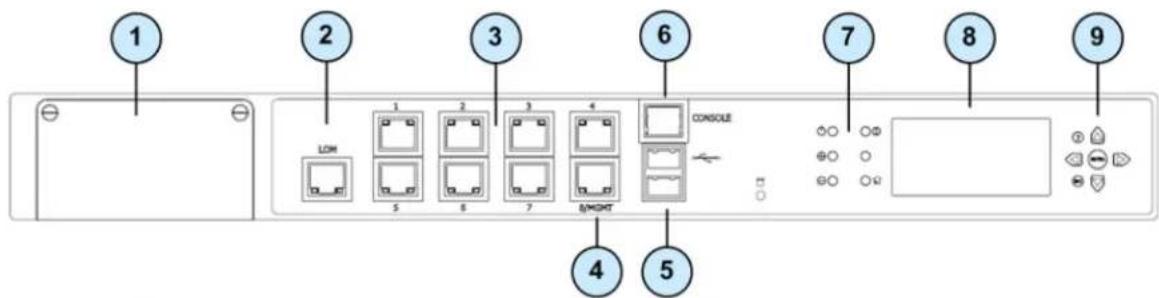
| Item | Component | Description |
| 1 | Expansion line card | Expansion slot |
| 2 | LOM Port | LOM (Light Out Management) port for the optional LOM card |
| 3 | Built in Ethernet ports | ETH1 - ETH7 |
| 4 | Management configuration port | Ethernet connection to a remote management workstation |
| 5 | USB ports | |
| 6 | Console port | A serial connection to the appliance using a terminal emulation program such as HyperTerminal or PuTTY |
| 7 | System LEDs | System power, system status, and hard disk activity |
| 8 | LCD display screen | |
| 9 | Keypad | Perform basic management operations |
Expansion Line Card Options
Expansion line cards can have two, four, or eight ports. These types of expansion line cards are available:
| Model | Description |
| CPAC-2-10F | 2 Port 10GBase-F SFP+ (without transceivers) |
| CPAC-4-1C | 4 Port 10/100/1000Base-T RJ-45 |
| CPAC-4-1F | 4 Port 1000Base-F SFP (without transceivers) |
| CPAC-4-10F | 4 Port 10GBase-F Ethernet PCI-e SFP+ |
| CPAC-8-1C | 8 Port 10/100/1000Base-T RJ-45 |
Check Point 12400 VSX Front Panel
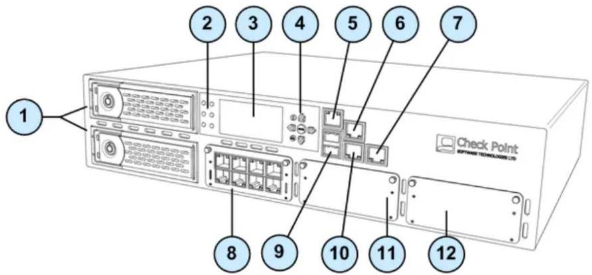
| Item | Component | Description |
| 1 | 2 Hard disk drives | When monitoring the disks using the raid_diagnostic command, DiskID 0 is the top disk, and DiskID 1 is the bottom disk |
| 2 | System LEDs | System power, system status, and hard disk activity |
| 3 | LCD screen | |
| 4 | Keypad | Perform basic management operations |
| 5 | Console port | For a serial connection to the appliance using a terminal emulation program such as HyperTerminal |
| 6 | Management port | For an Ethernet connection to a remote management computer |
| 7 | LOM port | LOM (Light Out Management) port for the optional LOM card |
| 8 | Expansion line card | 8 Port 10/100/1000Base-T RJ-45. Model: CPAP-ACC-8-1C |
| 9 | USB ports | |
| 10 | Synchronization port | For synchronizing with cluster members or a high availability peer |
| 11 | Expansion line card | Expansion slot |
| 12 | Expansion line card | Expansion slot |
Expansion Line Card Options
Expansion line cards can have two, four, or eight ports. These types of expansion line cards are available:
| Model | Description |
| CPAC-2-10F | 2 Port 10GBase-F SFP+ (without transceivers) |
| CPAC-4-1C | 4 Port 10/100/1000Base-T RJ-45 |
| CPAC-4-1F | 4 Port 1000Base-F SFP (without transceivers) |
| CPAC-4-10F | 4 Port 10GBase-F Ethernet PCI-e SFP+ |
| CPAC-8-1C | 8 Port 10/100/1000Base-T RJ-45 |
Check Point 12600 VSX Front Panel
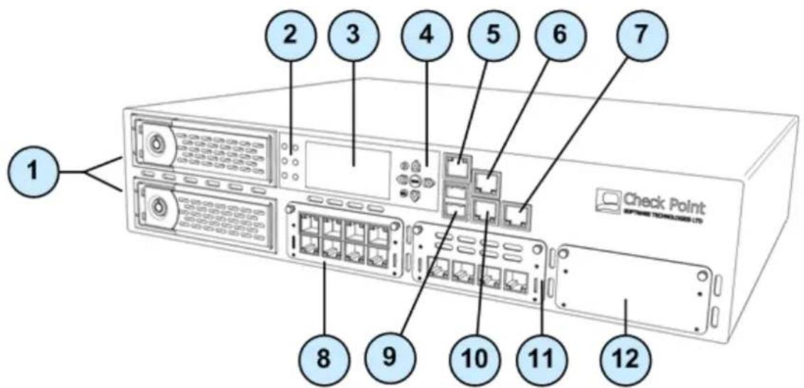
| Item | Component | Description |
| 1 | 2 Hard disk drives | When monitoring the disks using the raid_diagnostic command, DiskID 0 is the top disk, and DiskID 1 is the bottom disk |
| 2 | System LEDs | System power, system status, and hard disk activity |
| 3 | LCD screen | |
| 4 | Keypad | Perform basic management operations |
| 5 | Console port | For a serial connection to the appliance using a terminal emulation program such as HyperTerminal |
| 6 | Management port | For an Ethernet connection to a remote management computer |
| 7 | LOM port | LOM (Light Out Management) port for the optional LOM card |
| 8 | Expansion line card | 8 Port 10/100/1000Base-T RJ-45. Model: CPAP-ACC-8-1C |
| 9 | USB ports | |
| 10 | Synchronization port | For synchronizing with cluster members or a high availability peer |
| 11 | Expansion line card | 4 Port 10/100/1000Base-T RJ-45. Model: CPAP-ACC-4-1C |
| 12 | Expansion line card | Expansion slot |
Expansion Line Card Options
Expansion line cards can have two, four, or eight ports. These types of expansion line cards are available:
| Model | Description |
| CPAC-2-10F | 2 Port 10GBase-F SFP+ (without transceivers) |
| CPAC-4-1C | 4 Port 10/100/1000Base-T RJ-45 |
| CPAC-4-1F | 4 Port 1000Base-F SFP (without transceivers) |
| CPAC-4-10F | 4 Port 10GBase-F Ethernet PCI-e SFP+ |
| CPAC-8-1C | 8 Port 10/100/1000Base-T RJ-45 |
Rear Panel Components
This section describes the hardware on the rear panel of the appliance.
Check Point 12200 VSX Rear Panel
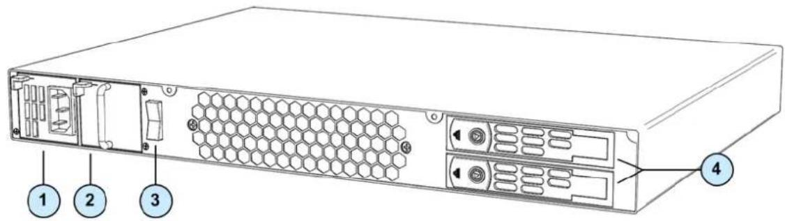
| Item | Component | Description |
| 1 | Power supply unit | If a power supply fails or is not connected to the outlet, an alarm sounds continuously. |
| 2 | Power supply placeholder unit | For appliances that are provisioned with one power supply unit, the placeholder unit is used in the other power supply slot.If both power supply slots are not populated, a continuous alarm sounds. |
| 3 | Main power switch | |
| 4 | Hard disk drives | When monitoring the disks using the raid_diagnostic command, DiskID 0 is the top disk, and DiskID 1 is the bottom disk. |
Check Point 12400 and 12600 VSX Rear Panel
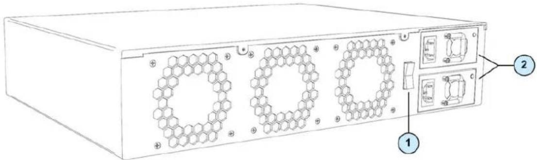
| Item | Component | Description |
| 1 | Main power switch | |
| 2 | Power supply units | If a power supply fails or is not connected to the outlet, an alarm sounds continuously |
Using the LCD Panel
The appliance has an LCD panel that you can use to do basic management operations. You can configure the management IP address, netmask, and default gateway of the appliance. You can reboot the appliance.
Menu Options
| Menu | Sub-menu | Purpose |
| Network | ||
| Set Mgmt IP | Set the management interface IP address. | |
| Set Netmask | Set the management interface network mask. | |
| Set Default GW | Set the management interface default gateway. | |
| System | ||
| Reboot | Reboot the appliance. |
LCD Panel Keys
| To | Press |
| Enter the main menu | [4CST] |
| Navigate the menu |  or ▼ or ▼ |
| Change a number |  or ▶ or ▶ |
| Select a menu option |  |
| Go back to previous menu |  |
When Entering an IP Address
| To | Press |
| Enter the grub menu |  or [IMAGE] or [IMAGE] |
| Move to the next digit |  |
| Move back to the previous digit |  |
| Approve the change |  when the cursor is located on the last digit when the cursor is located on the last digit |
| Cancel the IP change |  when the cursor is located on the first digit when the cursor is located on the first digit |
| Change current digit |  or [ZZWX] or [ZZWX] |
Customer Replaceable Parts
To ensure maximum availability and ease of maintenance, the Check Point 12000 VSX contains the following customer replaceable parts:
| 12200 VSX | 12400 VSX | 12600 VSX | |
| Power supply units | 1 Power supply unit1 Place holder unit | 2 | 2 |
| Expansion line card | 1 | 1 (2 optional slots) | 2 (1 optional slot) |
| Hard disk drives | 1 (1 optional slot)Located at rear of appliance | 1 (1 optional)Located at front of appliance | 2Located at front of appliance |
Unless directed to do so by Check Point technical support, customers are prohibited by warranty and support agreements from replacing any parts. Customers are prohibited from opening the appliance case under any circumstances.
Replacing Power Supplies
Check Point 12000 VSX have a redundant power supply. This section explains how to remove and install a power supply or placeholder unit.

Note - If both power supply slots are not populated, a continuous alarm sounds.
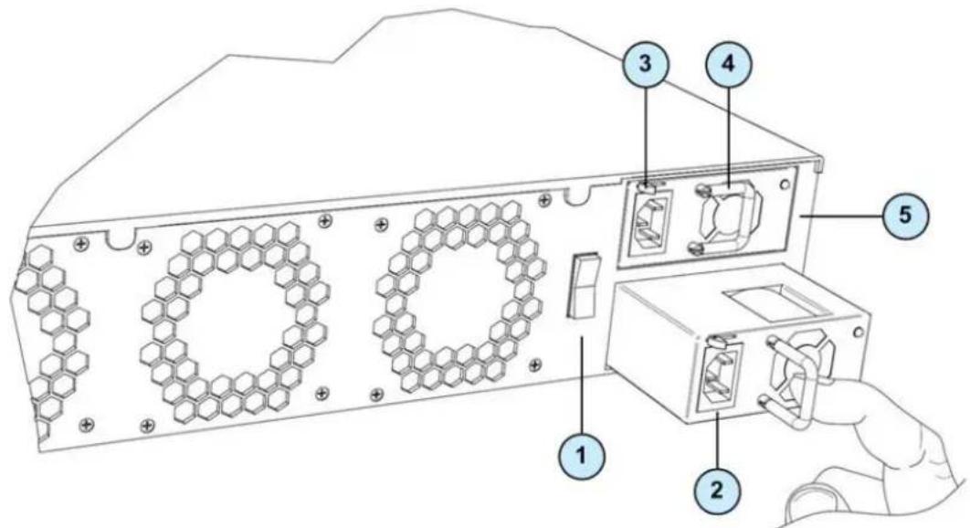
| Item | Description |
| 1 | Power switch |
| 2 | Power cord socket |
| 3 | Release lever |
| 4 | Extraction handle |
| 5 | Power supply unit |
Removing Power Supplies
This section describes how to remove a power supply or placeholder unit from the appliance.
natural_image
Line drawing of a rectangular electronic device with mounting holes and internal components (no text or symbols)To remove a power supply unit:
-
If the alarm sounds, press the red alarm button to the right of the power supply. The alarm stops.
-
Remove the power cord from the power supply unit.
-
Engage and hold the release lever on the power supply or placeholder unit.
-
Pull the extraction handle to remove the power supply or placeholder unit.

Note - Remove the power supply unit with the extraction handle to prevent any possible damage.
Installing Power Supplies
This section describes how to install a power supply or placeholder unit into the appliance.
To install a replacement power supply:
- Insert the power supply or placeholder unit into the power supply slot.
- Push the power supply or placeholder unit until the release lever clicks.
- Insert the power cord into the power supply socket. Make sure that the green LED is illuminated.
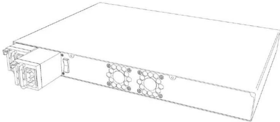
Replacing Expansion Line Cards
This section presents the procedures for removing and installing an expansion line card unit. There are two types of expansion cards that can be installed: Ethernet or Fiber Optic ports.

Important - Make certain that you are electromagnetically grounded when performing the following procedures. Static electricity can damage the appliance.
Check Point 12200 VSX
The built-in Ethernet ports (ETH1 - ETH7) are not customer replaceable.
natural_image
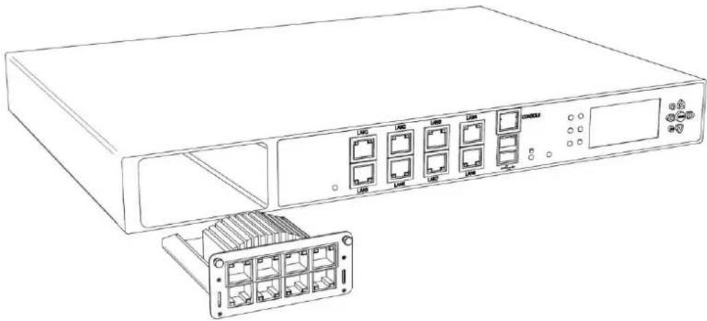
Line drawing of a network equipment chassis with multiple Ethernet ports and a separate rack-mounted unit (no text or symbols)Check Point 12400 and 12600 VSX
natural_image
Line drawing of a server rack with ports and a hand inserting a cable (no text or symbols visible)Removing Expansion Line Cards
To remove an expansion line card:
- Power off the appliance and remove the power cords from the power supply units.
- Loosen the retaining screws on the expansion line card.
- Holding the screws, pull the expansion line card out of the expansion slot.
- Place the metal cover over the expansion slot.
- Tighten the screws on the metal cover.
Installing Expansion Line Cards
To install an expansion line card:
- Power off the appliance and remove the power cords from the power supply units.
- Loosen the retaining screws on the metal cover on the front of the appliance.
- Holding the screws, remove the metal cover.
- Insert the expansion line card into the expansion slot.
- Push until the card clicks into place.
- Tighten the retaining screws on the expansion line card.
Replacing Hard Disk Drives on Check Point 12200 VSX
This section describes how to remove or install a hard disk drive in a Check Point 12200 VSX appliance.
natural_image
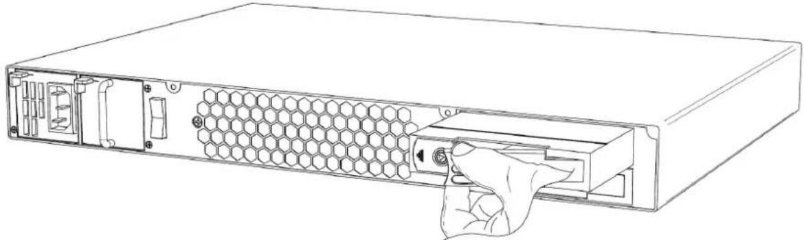
Line drawing of a server rack with hexagonal mesh panel and hand inserting a button (no text or symbols)Removing a Hard Disk Drive
To remove a hard disk drive from a Check Point 12200 VSX:
- Using the key supplied in the toolkit, unlock the drive.
- Slide the release latch toward the left. The extraction handle pops out.
- Using the extraction handle, remove the drive from the slot.
Installing a Hard Disk Drive
To install a hard disk drive in a Check Point 12200 VSX:
- Slide the replacement hard disk drive into the slot.
- Push the extraction handle until it closes and the drive clicks into place.
- Using the key supplied in the toolkit, lock the new drive.
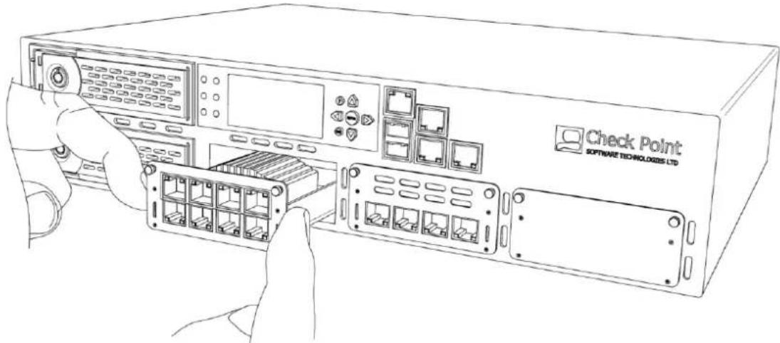
Replacing Hard Disk Drives on Check Point 12400 and 12600 VSX
This section describes how to remove or install a hard disk drive in a Check Point 12400 and 12600 VSX appliance.
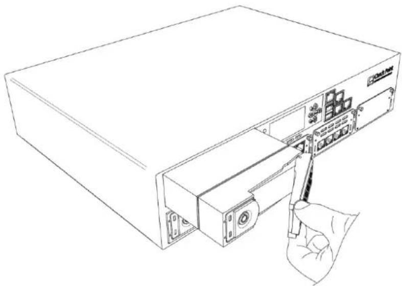
natural_image
Line drawing of a computer tower with a hand inserting a cable to the front panel (no text or symbols)Removing a Hard Disk Drive
To remove a hard disk drive from a Check Point 12400 and 12600 VSX:
- Using the key supplied in the toolkit, unlock the drive.
- Slide the release latch toward the left. The extraction handle pops out.
- Using the extraction handle, remove the drive from the slot.
Installing a Hard Disk Drive
To install a hard disk drive in a Check Point 12400 and 12600 VSX:
- Slide the replacement hard disk drive into the slot.
- Push the extraction handle until it closes and the drive clicks into place.
- Using the key supplied in the toolkit, lock the new drive.
VSX Appliance Recovery
VSX comes preloaded on your Check Point 12000 VSX appliance. If, for any reason, you need to reinstall VSX on the appliance, follow this procedure.
To reinstall VSX software on the appliance:
- Connect to the appliance console using the designated cord received in your shipping carton (RJ45/D-subminiature cable) and connect to the console using Terminal Emulation software, such as HyperTerminal or PuTTY.
- Load the Installation CD that you received in your shipping carton into a portable USB CD-ROM/DVD-ROM drive.
- Connect the portable CD-ROM/DVD-ROM drive to the appliance's USB socket.
- Power-On your appliance.
- Once the appliance boots from the CDROM/DVD drive, press Enter to start the installation.
- The installation automatically installs all required components and the progress of each stage is shown.
- When you see the message, "You may safely reboot your system," reboot the appliance manually using the master power button. Turn the appliance off and disconnect the USB CD-ROM/DVD-ROM. After several seconds, press the master power button to turn on the appliance again.
To install the existing security policy and configuration on the recovered gateway or cluster members:
- From the command line of the Security Manager server or Multi-Domain Security Management run: vsx_util reconfigure
- Enter the following information when prompted:
a) IP address of the Security Manager server or CMA that holds the VSX object
b) Administrator username and password
c) Gateway or Cluster member object name
d) SIC activation key for the recovered gateway or cluster member
- Reboot the reconfigured gateway or Cluster member.
The VSX appliance now contains the security policy and is part of the network configuration. For more information about the vsx_util reconfigure command, see the VSX NGX R67 Administration Guide (http://supportcontent.checkpoint.com/documentation_download?ID=10165).
Registration and Support
In This Chapter
Registration 35
Support 35
Where To From Here? 35
Registration
Check Point 12000 VSX requires a specific Check Point license. Obtain a license and register at the Check Point Appliance Registration site (http://register.checkpoint.com/cpapp).

Note - The MAC address of the management interface is required to obtain a license.
Support
For additional technical information about Check Point products, consult the Check Point Support Center (http://supportcenter.checkpoint.com).
Where To From Here?
You have now learned the basics that you need to get started. The next step is to obtain more advanced knowledge of your Check Point software.
See the VSX NGX R67 Administration Guide
(http://supportcontent.checkpoint.com/documentation_download?ID=10165), also available on the CD.
Check Point documentation is available on the Check Point Support Center (http://supportcenter.checkpoint.com).
Be sure to also use the Online Help when you are working with the Check Point SmartConsole clients.
Compliance Information
This appendix contains declaration of conformity, compliance, and related regulatory information.
In This Appendix
Declaration of Conformity 36
Declaration of Conformity
Manufacturer's Name: Check Point Software Technologies Ltd.
Manufacturer's Address: 5 Ha'Solelim Street, Tel Aviv 67897, Israel
Declare that under our sole responsibility the products
Model Number: P-210, P-220, and P-230
Product Options: All
Date First Applied: July, 2011
Conforms to the following product specifications:
| EMC | FCC, 47 CFR, Part 15, Class A | Information Technology Equipment - Radio Disturbance Characteristics |
| VCCI V-3, Class A | Information Technology Equipment - Radio Disturbance Characteristics | |
| AS/NZS CISPR22, Class A | Information Technology Equipment - Radio Disturbance Characteristics | |
| ICES-003, Class A | Information Technology Equipment - Radio Disturbance Characteristics | |
| CISPR22 | Information Technology Equipment - Radio Disturbance Characteristics | |
| EN55022, Class A | Information Technology Equipment - Radio Disturbance Characteristics | |
| EN 61000-3-2 | Information Technology Equipment - Harmonics Characteristics | |
| EN61000-3-3 | Information Technology Equipment - Flicker Characteristics | |
| EN 55024 | Information Technology Equipment - Immunity Characteristics | |
| EN61000-4-2 | Information Technology Equipment - Electrostatic Discharge Immunity | |
| EN61000-4-3 | Information Technology Equipment - Radiated RF Immunity | |
| EN61000-4-4 | Information Technology Equipment - Fast Transient Immunity | |
| EN61000-4-5 | Information Technology Equipment - Surge Immunity | |
| EN61000-4-6 | Information Technology Equipment - Conducted RF Immunity | |
| EN61000-4-11 | Information Technology Equipment - Voltage Dips and Short Interruptions Immunity | |
| Safety | CAN/CSA, C22.2 No. 60950-1-07 | Safety of Information Technology Equipment |
| UL 60950-1:2007 second edition | Safety of Information Technology Equipment | |
| EN 60950-1:2006/A11:2009 | Safety of Information Technology Equipment |
The product herewith complies with the requirements of the EU Directive 2006/95/EC and the EMC Directive 2004/108/EC
Date and Place of issue: July, 2011, Tel Aviv, Israel
FCC Notice (US)
This equipment has been tested and found to comply with the limits for a Class A digital device, pursuant to part 15 of the FCC Rules. These limits are designed to provide reasonable protection against harmful interference when the equipment is operated in a commercial environment. This equipment generates, uses, and can radiate radio frequency energy and, if not installed and used in accordance with the instruction manual, may cause harmful interference to radio communications. Operation of this equipment in a residential area is likely to cause harmful interference in which case the user will be required to correct the interference at his own expense.
Caution
Any changes or modifications not expressly approved by the grantee of this device could void the user's authority to operate the equipment.