
CL-37004518 - Memory Syba - Free user manual and instructions
Find the device manual for free CL-37004518 Syba in PDF.


| Product Type | Front Panel I/O Box |
| Brand | Syba |
| Model | CL-37004518 |
| Category | Memory |
| Form Factor | 5.25" bay |
| Power Connector | 4-pin SATA power (+12V or +5V) |
| USB Ports | 2 x USB 2.0 (4-pin) |
| IEEE 1394 Port | 1 x 6-pin FireWire |
| Audio Ports | Microphone, LINE-OUT (AC'97 compatible) |
| S/PDIF Connector | Digital audio out |
| Serial ATA Ports | 1 x SATA (with 4-pin power) |
| Card Reader | SM, CF/MD, SD/MMC, MS slots |
| USB Cable Pinout | Red (VCC), White (D-), Green (D+), Black (GND) |
| 1394 Cable Pinout | Black (GND), Blue (IPKa), Orange (IPKa), Green (IPKa), Red (IPKa), White (+12V) |
| Audio Cable Pinout | GND, MIC_IN, MIC_PWD, etc. |
| Compatible OS | Windows, Linux (with legacy USB support) |
| BIOS Settings | USB Function, Legacy USB Support, USB 2.0 Controller, USB 2.0 Controller Mode |
| Installation | Screw into 5.25" bay, connect cables to motherboard headers |
Frequently Asked Questions - CL-37004518 Syba
User questions about CL-37004518 Syba
0 question about this device. Answer the ones you know or ask your own.
Ask a new question about this device
Download the instructions for your Memory in PDF format for free! Find your manual CL-37004518 - Syba and take your electronic device back in hand. On this page are published all the documents necessary for the use of your device. CL-37004518 by Syba.
USER MANUAL CL-37004518 Syba
Front panel I/O BOX with connected cables
INSTALLATION:
A. Make sure the computer power is off after shut down the computer, and then open the cover of the computer.
B. Remove the 5.25"plastic cover from the computer where is the free bay you want to install.

C. Install the I/O front panel to the empty bay, and screw it.
D. Connect the attached cables from the I/O FRONT PANEL to the correct connectors where are on the motherboard when the I/O FRONT PANEL BOX is installed.
E. Connect with the Power Connector from the power supply to I/O Front Panel. Please refer to the picture below:

F.
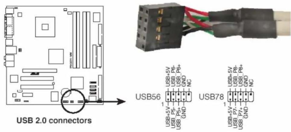
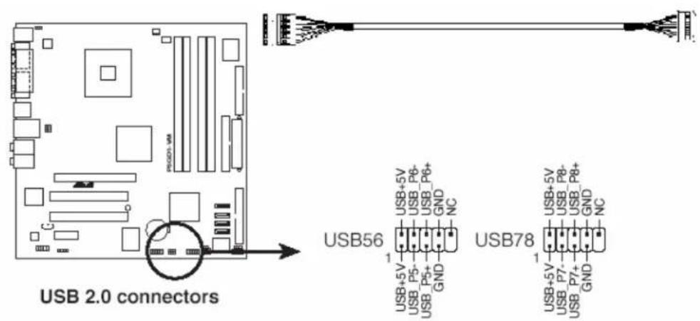
1. USB Port
Plug the USB module cable to the USB 2.0 connectors which is on the motherboard.
2. Audio Port
Plug in the Audio Module Cable to the legacy AC'97 Audio pin header where is located on the motherboard.


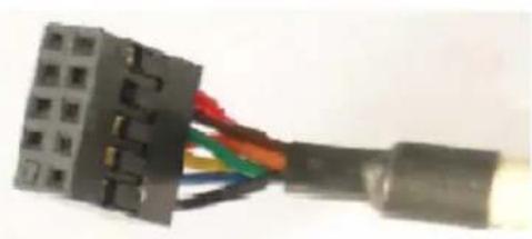
3.1394 Port
Plug the 1394 cable to the 1394 Port where is on the motherboard and make sure all the pins of connector which is connected are correct.

IEEE 1394 Connector
natural_image
Close-up of a black electrical connector with multiple colored wires (red, green, blue) connected to its body (no visible text or symbols)
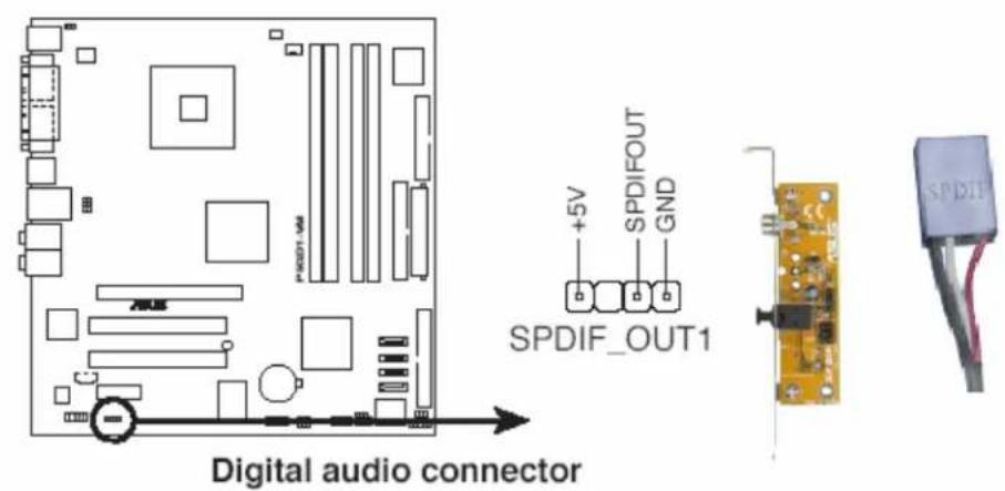
4. SPDIF\_OUT
Connect the S/PDIF module cable to the S/PDIF connector which is on the Motherboard.
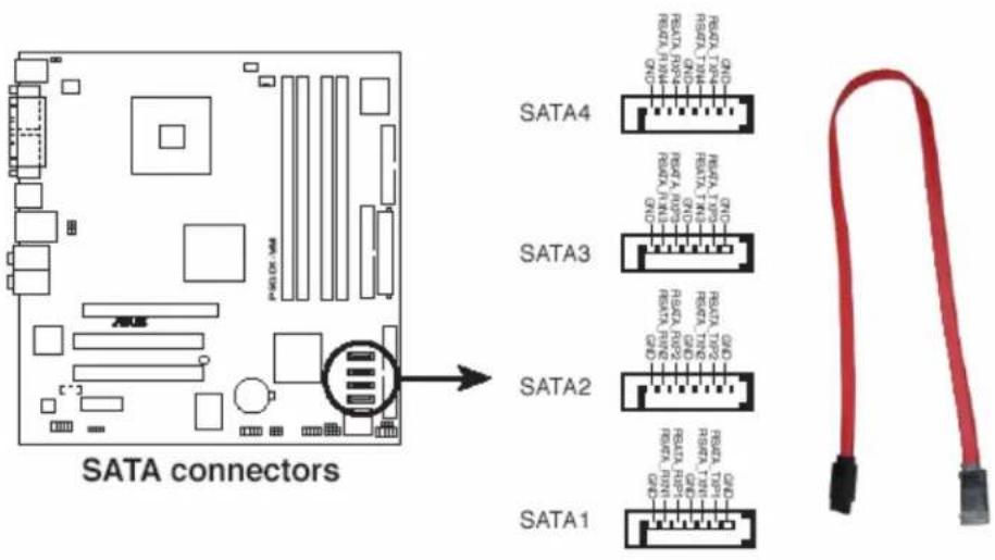
5. Serial ATA Port
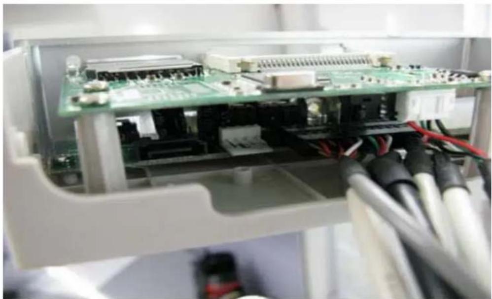
First Make sure the 4-pin power cable that from Power supply is connected to the correct location of the I/O board, and then plug the Serial ATA cable connecting to the Serial ATA port on the Motherboard from I/O PANEL.
natural_image
Interior view of an electronic device showing a green circuit board with connectors and wiring, no visible text or symbols.
These connectors are for the Serial ATA signal cables for Serial ATA hard disk drives.
6. Card Reader
Connect with the 5-pin USB cable from CN1 location of the Card reader PCB to another USB port where is on the motherboard.
Front panel I/O Box Connectors

- USB 2.0 Port: These two 4-pin Universal Serial Bus ports are available for connecting with USB 2.0 devices.
- IEEE 1394: This 6-pin firewire connector is for IEEE1394 device.
- SM Connector: This port is used for connecting with memory SM card.
- CF/MD Connector: This port is used for connecting with memory CF or MD card.
-
SD/MMC Connector: This port is used for connecting with memory SD or MMC card.
-
MS Connector: This port is used for connecting with memory MS card
- 8.S/PDIF digital sound Connector: The technology turns your computer into a high-end entertainment system with a digital connector for powerful audio and speaker systems.
- Microphone Connector: This port is used to connecting with a microphone.
- LINE-OUT Connector: This port is used to connecting with a headphone or a speaker.
- DC Power Connector: This 4-pin connector is used for connecting with SATA Power +12V or +5V.
- SATA Connector: This port is used for connecting with Serial ATA Equipment.
The cables choose Here you can choose the kinds cables that attached
to I/O BOX
1.

| PIN ASSIGNMENT | |
| COLOR P1 L1 | |
| RED 1 | USB_VCC |
| WHITE 3 | D- |
| GREEN 5 | D+ |
| BLACK 7 | G sound |
| DRAIN 7 | Technical |
| PIN ASSIGNMENT | |
| COLOR P1 L2 | |
| RED 2 | USB_VCC |
| WHITE4 | D- |
| GREEN6 | D+ |
| BLACK8 | Ground |
| DRAIN8 | Technical |
| PIN ASSIGNMENT | ||
| COLOR | P2 | L3 |
| BLACK | 4 | Ground |
| BLUE | 2 | IPKa |
| ORANGE1 | IPKa | |
| GREEN | 6 | IPKa |
| RED | 5 | IPKa |
| WHITE | 7 | +12V |
| DRAIN | 3 | Terminal |
| PIN ASSIGNMENT | ||
| COLOR | P3 | L4 |
| RED | 1 | WCC |
| WHITE | 3 | IN |
| DRAIN | 4 | Ground |
| PIN ASSIGNMENT | ||
| COLOR | P4 | LS |
| DRAIN | 1 | Ground |
| GREEN | 2 | MIC_IN |
| BLACK | 4 | MIC_PWD |
| YELLOW | 5 | PGT_D |
| ORANGE | 6 | L_BUT |
| RED | 9 | PGT_L |
| BROWN | 10 | L_BUT |
| PIN ASSIGNMENT | |
| COLOR P5 L6 | |
| RED 1 | USA_VCC |
| WHITE 2 | D- |
| GREEN 3 | D+ |
| BLACK 4 | Ground |
| DRAIN 5 | Ground |
2.

| PIN ASSIGNMENT | |
| COLOR P6 L6 | |
| DRAIN 3 Ground | |
| WHITE 2 LOW | |
| RED 1 R_OUT |
| PIN ASSIGNMENT | |
| COLOR P7 17 | |
| DRAIN 3 ———Ground | |
| WHITE 2 ———MIC_PMR | |
| RED 1 ———MIC_IN |
BIOS setup program
USB Configuration
The items in this menu allows you to change the USB-related features. Select an item then press
| BIOS SETUP UTILITY | |
| USB Configuration | Enables USB host controllers. |
| Module Version - 2.23.2-9.4 | |
| USB Devices Enabled: None | |
| USB Function [Enabled] | |
| Legacy USB Support [Auto] | |
| USB 2.0 Controller [Enabled] | |
| USB 2.0 Controller Mode [HiSpeed] | |

The Module Version and USB Devices Enabled items show the auto-detected values. If no USB device is detected, the item shows None.
USB Function [Enabled]
Allows you to enable or disable the USB function.
Configuration options: [Disabled] [Enabled]
Legacy USB Support [Auto]
Allows you to enable or disable support for USB devices on legacy operating systems (OS). Setting to Auto allows the system to detect the presence of USB devices at startup. If detected, the USB controller legacy mode is enabled. If no USB device is detected, the legacy USB support is disabled. Configuration options: [Disabled] [Enabled] [Auto]
USB 2.0 Controller [Enabled]
Allows you to enable or disable the USB 2.0 controller.
Configuration options: [Disabled] [Enabled]
USB 2.0 Controller Mode [HiSpeed]
Allows you to configure the USB 2.0 controller in HiSpeed (480 Mbps) or Full Speed (12 Mbps). Configuration options: [HiSpeed] [Full Speed]
Brand : Syba
Model : CL-37004518
Category : Memory