
TPM2020 - Wall mount for screen Chief - Free user manual and instructions
Find the device manual for free TPM2020 Chief in PDF.


| Product Type | Wall Mount for Screen |
| Brand | Chief |
| Model | TPM2020 |
| Series | TPM-2000 Series |
| Maximum Weight Capacity | 150 lbs (68 kg) |
| Tilt Range | 5° up to 15° down |
| Vertical Pole Compatibility | 1" - 3" O.D. |
| Horizontal Pole Compatibility | 1" - 2" O.D. |
| Mounting Type | Pole Mount (Vertical or Horizontal) |
| Included Accessories | Hex Key (5/32"), Mount (TPM-2000) |
| Required Accessories (Not Included) | Chief Pole Kit (TPK-1 or TPK-2) |
| Interface Bracket | Custom Interface Bracket (sold separately, adds 1/2" to 2" depth) |
| Display Attachment | Q-Latch system with locking hole for padlock |
| Pitch Adjustment | Yes, with screws and optional locking holes at 0°, 5°, 10° |
| Roll Adjustment | Yes, with upper and lower nuts |
| Safety Warning | Structure must support 5x combined weight; maximum weight 150 lbs; keep latch closed |
| Material | Steel (estimated) |
| Tools Required | 7/16" Wrench (optional for locking screws), 5/32" Hex Key (included) |
| Installation Orientation | Upward arrow indicates correct orientation (see figures) |
| Product Category | Wall Mount |
Frequently Asked Questions - TPM2020 Chief
User questions about TPM2020 Chief
0 question about this device. Answer the ones you know or ask your own.
Ask a new question about this device
Download the instructions for your Wall mount for screen in PDF format for free! Find your manual TPM2020 - Chief and take your electronic device back in hand. On this page are published all the documents necessary for the use of your device. TPM2020 by Chief.
USER MANUAL TPM2020 Chief
INSTALLATION INSTRUCTIONS
POLE/PITCH- ADJUSTABLE MOUNT
Model: TPM-2000 SERIES
Specifications:
• Weight capacity of 150 lbs. (68 kg).
• Provides tilt range from 5° up to 15° down.
• Accommodates vertical pole (1° - 3° O.D.) or
horizontal pole installation (1" - 2" O.D.).

natural_image
Technical line drawing of a mechanical component with multiple circular holes and mounting flanges (no text or symbols)
IMPORTANT WARNINGS AND CAUTIONS!
WARNING: A WARNING alerts you to the possibility of serious injury or death if you do not follow the instructions.
CAUTION: A CAUTION alerts you to the possibility of damage or destruction of equipment if you do not follow the corresponding instructions.

WARNING: It is the installer's responsibility to make sure the structure to which this unit is attached can support five times the combined weight of all equipment. Reinforce the structure as required before installing the unit. Failure to provide adequate structural strength for this unit can result in serious personal injury or damage to equipment!

WARNING: It is the installer's responsibility to make sure the combined weight of the display, mount, accessories, and any other attached equipment must not exceed 150 lbs (68 kg), the maximum support weight of this unit. Exceeding the maximum support weight can result in serious personal injury or damage to equipment!

WARNING: Make sure the latch securing the display is fully closed at all times except when removing or installing the display. The latch must be fully closed when installing or removing cables from the display.

WARNING: Watch for pinch points. Do not put your fingers between movable parts.
DIMENSIONS


natural_image
Technical line drawing of a mechanical component with multiple circular cutouts and mounting holes (no text or symbols)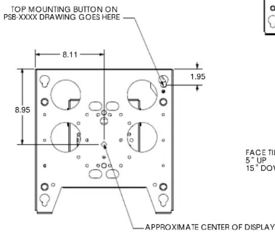

NOTE: CUSTOM INTERFACE BRACKET NOT SHOWN. THE CUSTOM INTERFACE BRACKET NEEDED FOR YOUR DISPLAY WILL ADD BETWEEN 1/2" AND 2" IN DEPTH AND MAY AFFECT LOCATION OF DISPLAY ON THE MOUNT.
SEE PSB-XXXX DRAWING ALSO.
TOOLS REQUIRED FOR INSTALLATION
- 7/16" Wrench (optional; see Pitch (Tilt) Adjustment for detail)
- 5/32" Hex Key (provided)
NOTE: Other tools may be required depending on your method of installation.
PARTS
After unpacking carton, inspect and verify contents (see Figure 1).
Table 1: Parts
| Item Description Qty | ||
| 10 MOUNT, TPM-2000 1 | ||
| 20 KEY, Hex, 5/32" 1 | ||
| --- POLE | KIT (TPK-1 or TPK-2)(required, not supplied) | 1 |

Figure 1: Parts
INSTALLATION
MOUNT INSTALLATION
- Install mount to pole:
NOTE: See instructions that come with Chief Pole Kit for installation details.
- Vertical Pole: Use optional Chief Pole Kit TPK-1 (for 1"-2" O.D. poles) or TPK-2 (for 2"-3" O.D. poles) (see Figure 2). Ensure mount is properly oriented (see Figure 4).
- Horizontal Pole: Use optional Chief Pole Kit TPK-1 (for 1"-2" O.D. poles)(see Figure 3). Ensure mount is properly oriented (see Figure 5).
NOTE: Horizontal pole installation is not compatible with Pole Kit TPK-2.

Figure 2: Vertical Pole Installation (Typical)

Figure 3: Horizontal Pole Installation (Typical)

natural_image
Technical line drawing of a mechanical component with circular holes and an upward arrow labeled 'UP' (no text or symbols on the diagram itself)Figure 4: Vertical Mount Orientation

Figure 5: Horizontal Mount Orientation
DISPLAY INSTALLATION
NOTE: Interface bracket may be required.
If required, interface bracket must be installed prior to display installation.

WARNING: Display may be heavy! Ensure display can be safely lifted and maneuvered as required to attach to mount. Failure to take adequate precautions can result in serious personal injury or damage to equipment!
- Rotate Q-Latch to the OPEN position (see Figure 6).

Figure 6: Open Q-Latch
- Lift and maneuver display such that all mounting buttons fit into button openings on faceplate. Lower display firmly into place. Ensure each button has fully seated in its button opening (see Figure 7).
NOTE: If Q-Latch does not fully engage, ensure the mounting buttons are fully seated in the button openings.


Figure 7: Align Display
- Rotate Q-Latch to the CLOSED position (see Figure 8).
NOTE: A hole is provided in the Q-Latch and faceplate to accommodate the insertion of a padlock or similar
locking device.

Figure 8: Close Q-Latch
- Attach all cables to display.
ADJUSTMENTS
Pitch (Tilt) Adjustment
-
Loosen right and left pitch adjustment screws (see Figure 9).
-
Position display to desired angle.
-
Tighten pitch adjustment screws (see Figure 9).
- The display may be locked at any position between 5^ tilt up and 15^ tilt down by tightening the pitch adjustment screws.
However, if additional locking security is desired, use key (20) and a 7/16" wrench to remove the locking screw(s) from the stored location(s) and install into the 0°, 5°, or 10° pitch lock hole(s).

Figure 9: Pitch Adjustment
Roll Adjustment
The TPP-2000 Series mount provides for limited roll adjustment to level the display after installation (see Figure 10).

Figure 10: Roll
To adjust display roll:
- Loosen upper and lower roll adjustment nuts (see Figure 11).
- Level Display.
- Tighten roll adjustment nuts (see Figure 11).

Figure 11: Roll Adjustment



Brand : Chief
Model : TPM2020
Category : Wall mount for screen