RMS Interface for Lotus - Software AMX - Free user manual and instructions
Find the device manual for free RMS Interface for Lotus AMX in PDF.


| Product Type | Software |
| Brand | AMX |
| Model | RMS Interface for Lotus |
| Category | Integration Software |
| Intended Use | Interface for Resource Management System (RMS) with Lotus Notes/Domino |
| Compatibility | Lotus Notes and Lotus Domino |
| Platform | Microsoft Windows (32-bit and 64-bit) |
| Manual Format | |
| Manual Pages | 206 |
| Manual Language | English (EN) |
| Download Availability | Free from manufacturer website |
| Key Feature | Seamless integration between RMS and Lotus Notes |
| Key Feature | Real-time data synchronization |
| Key Feature | Supports automated workflows |
| Installation | Standard software installation with setup wizard |
| Security | User authentication and role-based access control |
| Maintenance | Regular software updates available from AMX |
| Support | Online documentation and technical support |
| Distributor | AMX |
Frequently Asked Questions - RMS Interface for Lotus AMX
User questions about RMS Interface for Lotus AMX
0 question about this device. Answer the ones you know or ask your own.
Ask a new question about this device
Download the instructions for your Software in PDF format for free! Find your manual RMS Interface for Lotus - AMX and take your electronic device back in hand. On this page are published all the documents necessary for the use of your device. RMS Interface for Lotus by AMX.
USER MANUAL RMS Interface for Lotus AMX
AMX Software License and Warranty Agreement
- LICENSE GRANT. AMX grants to Licensee the non-exclusive right to use the AMX Software in the manner described in this License. The AMX Software is licensed, not sold. This license does not grant Licensee the right to create derivative works of the AMX Software. The AMX Software consists of generally available programming and development software, product documentation, sample applications, tools and utilities, and miscellaneous technical information. Please refer to the README.TXT file on the compact disc or download for further information regarding the components of the AMX Software. The AMX Software is subject to restrictions on distribution described in this License Agreement. AMX Dealer, Distributor, VIP or other AMX authorized entity shall not, and shall not permit any other person to, disclose, display, loan, publish, transfer (whether by sale, assignment, exchange, gift, operation of law or otherwise), license, sublicense, copy, or otherwise disseminate the AMX Software. Licensee may not reverse engineer, decompile, or disassemble the AMX Software.
- ACKNOWLEDGEMENT. You hereby acknowledge that you are an authorized AMX dealer, distributor, VIP or other AMX authorized entity in good standing and have the right to enter into and be bound by the terms of this Agreement.
- INTELLECTUAL PROPERTY. The AMX Software is owned by AMX and is protected by United States copyright laws, patent laws, international treaty provisions, and/or state of Texas trade secret laws. Licensee may make copies of the AMX Software solely for backup or archival purposes. Licensee may not copy the written materials accompanying the AMX Software.
• TERMINATION. AMX RESERVES THE RIGHT, IN ITS SOLE DISCRETION, TO TERMINATE THIS LICENSE FOR ANY REASON UPON WRITTEN NOTICE TO LICENSEE. In the event that AMX terminates this License, the Licensee shall return or destroy all originals and copies of the AMX Software to AMX and certify in writing that all originals and copies have been returned or destroyed. - PRE-RELEASE CODE. Portions of the AMX Software may, from time to time, as identified in the AMX Software, include PRE-RELEASE CODE and such code may not be at the level of performance, compatibility and functionality of the GA code. The PRE-RELEASE CODE may not operate correctly and may be substantially modified prior to final release or certain features may not be generally released. AMX is not obligated to make or support any PRE-RELEASE CODE. ALL PRE-RELEASE CODE IS PROVIDED "AS IS" WITH NO WARRANTIES.
- LIMITED WARRANTY. AMX warrants that the AMX Software (other than pre-release code) will perform substantially in accordance with the accompanying written materials for a period of ninety (90) days from the date of receipt. AMX DISCLAIMS ALL OTHER WARRANTIES, EITHER EXPRESS OR IMPLIED, INCLUDING, BUT NOT LIMITED TO IMPLIED WARRANTIES OF MERCHANTABILITY AND FITNESS FOR A PARTICULAR PURPOSE, WITH REGARD TO THE AMX SOFTWARE. THIS LIMITED WARRANTY GIVES LICENSEE SPECIFIC LEGAL RIGHTS. Any supplements or updates to the AMX SOFTWARE, including without limitation, any (if any) service packs or hot fixes provided to Licensee after the expiration of the ninety (90) day Limited Warranty period are not covered by any warranty or condition, express, implied or statutory.
- LICENSEE REMEDIES. AMX's entire liability and Licensee's exclusive remedy shall be repair or replacement of the AMX Software that does not meet AMX's Limited Warranty and which is returned to AMX in accordance with AMX's current return policy. This Limited Warranty is void if failure of the AMX Software has resulted from accident, abuse, or misapplication. Any replacement AMX Software will be warranted for the remainder of the original warranty period or thirty (30) days, whichever is longer. Outside the United States, these remedies may not available. NO LIABILITY FOR CONSEQUENTIAL DAMAGES. IN NO EVENT SHALL AMX BE LIABLE FOR ANY DAMAGES WHATSOEVER (INCLUDING, WITHOUT LIMITATION, DAMAGES FOR LOSS OF BUSINESS PROFITS, BUSINESS INTERRUPTION, LOSS OF BUSINESS INFORMATION, OR ANY OTHER PECUNIARY LOSS) ARISING OUT OF THE USE OF OR INABILITY TO USE THIS AMX SOFTWARE, EVEN IF AMX HAS BEEN ADVISED OF THE POSSIBILITY OF SUCH DAMAGES. BECAUSE SOME STATES/COUNTRIES DO NOT ALLOW THE EXCLUSION OR LIMITATION OF LIABILITY FOR CONSEQUENTIAL OR INCIDENTAL DAMAGES, THE ABOVE LIMITATION MAY NOT APPLY TO LICENSEE.
- U.S. GOVERNMENT RESTRICTED RIGHTS. The AMX Software is provided with RESTRICTED RIGHTS. Use, duplication, or disclosure by the Government is subject to restrictions as set forth in subparagraph ©(1)(ii) of The Rights in Technical Data and Computer Software clause at DFARS 252.227-7013 or subparagraphs ©(1) and (2) of the Commercial Computer Software Restricted Rights at 48 CFR 52.227-19, as applicable.
- SOFTWARE AND OTHER MATERIALS FROM AMX.COM MAY BE SUBJECT TO EXPORT CONTROL. The United States Export Control laws prohibit the export of certain technical data and software to certain territories. No software from this Site may be downloaded or exported (i) into (or to a national or resident of) Cuba, Iraq, Libya, North Korea, Iran, Syria, or any other country to which the United States has embargoed goods; or (ii) anyone on the United States Treasury Department's list of Specially Designated Nationals or the U.S. Commerce Department's Table of Deny Orders. AMX does not authorize the downloading or exporting of any software or technical data from this site to any jurisdiction prohibited by the United States Export Laws.
This Agreement replaces and supersedes all previous AMX Software License Agreements and is governed by the laws of the State of Texas, and all disputes will be resolved in the courts in Collin County, Texas, USA. For any questions concerning this Agreement, or to contact AMX for any reason, please write: AMX License and Warranty Department, 3000 Research Drive, Richardson, TX 75082.
Table of Contents
RMS Resource Management Suite ....1
Overview 1
Additional Documentation 1
What's New in RMS v3.3.... 1
Windows 2008 Server 1
System Requirements .... 1
Minimum Hardware Requirements.... 1
Supported Platforms.... 1
RMS Supported Databases 2
RMS Supported Scheduling and Mailbox Interfaces 2
RMS Supported Web Browsers 2
RMS SDK Support 2
Additional System Requirements 3
Windows 2008 Server - Required Features, Roles and Services.... 3
Network Configuration 4
RMS Application Install Checklist 4
Installation 5
The RMS SDK 5
Upgrading to RMS v3.3 From RMS v3.x.... 5
Upgrading to RMS v3.3 from RMS v2.2 Or Earlier.... 5
Conceptualizing the RMS Application.... 5
Licensing 5
Licensing Summary.... 5
Appointment Management Considerations 5
Messaging and Notification 5
Logging Configuration 6
Security 6
Windows Authentication 6
Enabling Integrated Windows Authentication.... 6
Vertical Market Support 7
Device Monitoring Framework 8
Device Values.... 8
Parameter Values 9
Status Types.... 10
Notification Process.... 10
Alert Messages.... 10
Advise Messages.... 11
Scheduling System Plug-ins 11
Getting Started 13
Running the Configuration Wizard.... 13
Adding NetLinx Systems As Rooms 13
Adding And Configuring Groups 13
Adding Users 13
Adding Notifications.... 14
Changing The Domain Path for Notifications 14
RMS Configuration Wizard 15
Overview 15
Appointment Management/Scheduling System 15
Database.... 16
Database - Connection 16
Database - Configuration 17
Database - Updates.... 17
Product Selection.... 18
Web Services 18
Web Services - Microsoft IIS Server.... 18
Web Services - Virtual Directory.... 19
Services.... 20
Services - Register 21
Services - Start 22
Licensing 23
Licensing Summary - Asset Licenses vs. Scheduling License.... 24
Licensing - Server Licenses 24
Enter Server Serial Number 25
Manual Authorization 25
Manually Authorizing Your RMS Server.... 25
Licensing - Client Licenses 26
OS Permissions 27
OS Permissions - Service User 27
OS Permissions - Web User 28
System Settings 29
System Settings - NetLinx 29
System Settings - Security 30
System Settings - Administrator.... 30
System Settings - Scheduling 31
System Settings - Appointments 32
System Settings - SMTP 33
System Settings - SNPP 34
System Settings - SNMP 35
System Settings - RFID Tracking 36
System Settings - Logging 36
System Settings - Syslog 37
System Settings - Reporting 38
System Settings - Time Sync.... 38
Name & Logo.... 39
Creating A Custom Logo 39
Finished 40
Database Wizard 41
Overview 41
Starting the Database Wizard.... 41
Main Menu 42
Configure Connection 43
Create / Remove 43
Import / Export 44
Create A New Database.... 44
Remove A Database 46
Importing Data 47
Exporting Data 47
Converting A Database 48
Applying Update Scripts 49
Configuring Connection Settings 50
RMS Web User Interface 51
Overview 51
Sign in Page 51
How do you sign in to RMS? 51
RMS Web User Interface.... 51
RMS Administration 53
Administration Page 53
RMS Dashboard Page 55
Overview 55
How Do You Change Modes? 55
Adding Contents.... 55
Add Contents.... 55
Restore Contents 56
Imported Web Part Catalog 56
Moving Columns 56
Resetting the RMS Dashboard.... 56
RMS Hotlist 57
Overview 57
Unassigned NetLinx Systems 57
Parameter Needing Attention 58
Viewing a Room When Appearing In Parameter Needing Attention List 58
Resetting a Room When Appearing In Parameter Needing Attention List.... 59
Responding To a Room When Appearing In Parameter Needing Attention 59
Room Troller Failure 59
System Status Page 61
Overview 61
Auto-Refresh....61
Viewing System Status Information 61
Viewing Device Information on the System Status Page 62
View Devices Page 62
Create Device Page 63
Execute Control Function Page 64
Device Information Page 65
Modify Device Information Page 67
Device Parameter Page 68
Device Parameter History Page.... 70
Modify Parameter Page.... 71
Viewing Device parameters.... 72
Viewing Device Parameter history 72
Deleting Device Parameter history.... 72
Modifying Device Parameters 72
Deleting Device Parameters.... 72
Viewing Detailed Device Information.... 73
Modifying Device Information 73
Moving a Device to a New Room 73
Deleting Device Information 74
Viewing a Device Log.... 74
Executing a Device Control Function 74
Management Page 75
Overview 75
Management - Rooms Page 75
Create New Group Page 75
Creating a New Group 76
Viewing Group Settings 76
View Group Setting Page 76
Editing a Group.... 76
Modify Group Setting Page 77
Deleting Groups.... 77
Create New Room Page.... 77
View Room Settings Page 79
Viewing Room Settings 79
Send Question Page.... 80
Creating a New Room 81
Editing a Room.... 81
Viewing Room settings.... 81
Deleting Rooms.... 81
Sending a Question to a Room 82
Management - Users Page 82
Create New User Account Page 83
Edit User Page 84
Creating a New User 84
Editing Users 84
How Do I Disable/Enable A User? 85
Deleting Users.... 85
Management - Permissions Page 85
Create New Role 86
Edit Role Page.... 87
Creating a New Role 87
Editing a Role 87
Deleting a Role.... 87
Management - Notifications Page 88
Create New Notification Page 89
Edit Notification Page 90
Creating a Notification.... 90
Editing a Notification 90
Deleting a Notification.... 90
Changing the Domain Path For Notifications.... 91
Management - Systems Page.... 91
View System Page 92
Viewing a System 92
Management - Devices Page 93
Create Device Page.... 93
Device Search Page.... 94
Management - Internal Log Page.... 95
Exporting an Internal Log.... 96
Viewing Exported Internal Logs 96
Deleting Exported Internal Logs 96
Management - Control Functions Page.... 96
Create Control Function Macro Page 97
Edit Macro Page.... 98
Schedule Macro Page 98
Control Function Macro Schedules Page.... 99
Creating a New Macro 99
Viewing a Macro.... 100
Executing a Macro.... 100
Deleting a Macro.... 100
Scheduling a Macro 100
Viewing a Macro Schedule 100
Management - RFID Tags Page.... 101
Tag Details Page 101
Assign Tag to Device Page.... 102
Reporting Page 103
System Reports Page 103
Room Reports 104
System Reports - Help Requests 104
System Reports - Help Requests Results 105
System Reports - Help Requests (Detailed) 105
System Reports - Help Requests (Detailed) Results.... 106
System Reports - Residence Usage 107
System Reports - Residence Usage Results 108
System Reports - Source Usage.... 108
System Reports - Source Usage Results 109
System Reports - Cumulative Lamp Hours.... 110
System Reports - Cumulative Lamp Hours Results 111
System Reports - Transport Run Time 112
System Reports - Transport Run Time Results 113
System Reports - Current Source Usage.... 114
System Reports - Current Source Usage Results 115
System Reports - Current Lamp Hour.... 116
System Reports - Current Lamp Hours Results 117
Power Reports 118
Power Reports - System Power 118
Power Reports - System Power Results 119
Power Reports - Device Power.... 119
Power Reports - Device Power Results 120
Power Reports - System Power (Detailed) 121
Power Reports - System Power (Detailed) Results 121
Quality of Service Reports 122
Quality of Service Reports - System Online.... 122
Quality of Service Reports - System Online Results 123
Quality of Service Reports - Device Online 124
Quality of Service Reports - Device Online Results 125
Quality of Service Reports - Device Communications.... 126
Quality of Service Reports - Device Communications Results 127
Quality of Service Reports - Device Control Failures.... 128
Quality of Service Reports - Device Control Failures Results 129
Scheduler Reports 129
Scheduler Reports - Help Requests 129
Scheduler Reports - Help Requests Results.... 130
Scheduler Reports - Help Requests (Detailed).... 131
Scheduler Reports - Help Requests (Detailed) Results 132
Scheduler Reports - Room Usage.... 132
Scheduler Reports - Room Usage Results.... 133
Scheduler Reports - Source Usage 134
Scheduler Reports - Source Usage Results 135
Running a System Report.... 135
Tracking Reports.... 137
Tracking Reports - Device Activity 137
Tracking Reports - Device Activity Results 138
Tracking Reports - Device Activity (Detailed) 138
Tracking Reports - Device Activity (Detailed) Results 139
Tracking Reports - Room Activity 140
Tracking Reports - Room Activity Results 141
Tracking Reports - Device Location.... 141
Tracking Reports - Device Location Results 142
Tracking Reports - Device Battery Levels 143
Tracking Reports - Device Battery Levels Results 144
Administrative Reports 145
Administrative Reports - Device Inventory.... 145
Administrative Reports - Device Inventory Results 145
Administrative Reports - Control System Inventory 146
Administrative Reports - Control System Inventory Results 147
Administrative Reports - System Users 147
Administrative Reports - System Users Results 148
Internal Log Report Page.... 148
Internal Log Entry Page.... 149
Viewing Log Entries 149
Adding Notes To Log Entries 149
Deleting Log Entries.... 149
Source Usage Page 150
Viewing Source Usage Reports 150
Lamp Hours Report Page.... 151
Viewing Lamp Hours Reports 151
Configuration Page 153
Appointment Settings Page.... 153
Configuring The System Storage Settings.... 153
Setting the Appointment Master Password 154
Configure Internal Log Page 154
Configuring the Internal Log 155
Enabling/Disabling Internal Log 155
Purging the Internal Log 155
Configure Notification Template Page 156
Create New Template Page 157
Viewing a Notification Template 159
Creating a new Notification Template.... 159
Deleting a Notification Template 159
Copying a Notification Template.... 160
Prestige Levels Page.... 160
Editing Prestige Levels.... 160
Enabling/Disabling Prestige Levels 160
System Licensing Page.... 161
Checking Client Licensing Information 162
Adding a Client License.... 162
Removing a Client License.... 162
Hotlist Settings Page 163
Creating a New Help Response.... 163
Editing a Help Response 163
Deleting a Help Response 163
Help Page 165
Overview 165
About RMS Application Page 165
Administrator's Guide.... 165
User's Guide 165
Version Information Page 165
View Readme.... 165
System Diagnostics 165
Status Page 165
Checking System Status 165
Connections Page 166
Checking RMS connections 166
Restarting Connection Server 166
Resources Page 166
Displaying/Hiding Resource Keys.... 166
Appending Culture Codes to Strings 166
Displaying the Resource Lookup Table 167
Debugging Page 167
Setting Debug Options And Debugging The RMS Server.... 167
Sitemap Page 169
Overview 169
RMS Scheduling Page 171
Overview 171
View Schedule Page 171
Day View Page.... 171
Opening Day View 171
Week View Page.... 172
Opening Week View 172
Month View Page 172
Opening Month View 173
Add Appointment Page.... 173
Appointment Details Page.... 175
Creating an Appointment 176
Creating an Appointment with an External Scheduler 176
Room Search Page 177
Room Search Results Page 178
Conducting a Room Search 178
RMS User Page 179
Sign in Page 179
How Do I Sign In To RMS? 179
Preferences Page.... 179
Setting the Default Language 179
Setting the Home Page.... 179
Resetting Column Sorting 179
Setting Scheduling View Hours 180
User Profile Page 180
Editing Your User Profile.... 180
Changing Your User Password 180
Setting User Notification Time Span 181
User Notifications Page 181
Create New Notification Page.... 181
Creating new User Notifications.... 182
Sign Out Page.... 182
Signing Out of RMS.... 182
RMS Touch Panel Pages 183
Overview 183
RMS Welcome Page.... 183
RMS Meeting Request Dialog.... 184
Finding a Meeting In a Room's Schedule 184
Creating a Meeting At The Welcome Panel 184
Extending a Meeting At the Welcome panel.... 185
Ending a Meeting Early At the Welcome panel.... 185
Ringing The Doorbell 186
RMS In-Room Page 187
Finding a Meeting In a Room's Schedule 188
Creating a Meeting At The In-Room Panel 188
Extending a Meeting At The In-Room Panel.... 188
Ending a Meeting Early At The In-Room Panel.... 189
Executing a Meeting Preset 189
Using the Room's Calendar 190
Setting the Meeting To "Do Not Disturb" 190
Placing a Help Request.... 191
Placing a Service Request.... 192
RMS Resource Management Suite
Overview
The AMX Resource Management Suite (RMS) is a line of software solutions designed for IT professionals, facility managers and meeting/classroom users looking for a way to manage, monitor and/or schedule up to 1,000 rooms and an unlimited number of assets. This document provides information and instructions for the RMS System Administrator.
Additional Documentation
Refer to the following supplemental RMS documents (available to view/download from www.amx.com):
- RMS Installation Checklist - The RMS Installation Checklist is provided to ensure all the necessary prerequisites are met and all the necessary configuration option are identified prior to the installation of the RMS server.
- RMS Database Administrators Guide - This document outlines the installation prerequisites, installation guidelines, database access permissions and other important database related information for the RMS database installation.
- RMS NetLinx Programmers Guide - This document provides detailed NetLinx programming information for RMS systems.
- RMS Plug In Installation Guides - A separate installation guide is provided to describe installing each of the RMS plug-ins (i.e. EMS Scheduling Plug-in, Exchange Mailbox Plug-in, Groupwise Mailbox Plug-in, Lotus Notes Appointment Interface Plug-in, Outlook Scheduling Plug-in, PeopleCube Scheduling Plug-in, Planon Scheduling Plug-in, R25 Scheduling Plug-in, etc.)
- RMS Quick Start Guide - This document provides basic instructions for getting started with RMS.
- RMS User Manual - This document describes various end-user functions of RMS.
What's New in RMS v3.3
- Refresh added to System Status and Devices pages
● Support for Multiple Lamp Hours on a projector - Scheduling Interfaces were removed from the standard RMS installation. See the RMS Supported Scheduling and Mailbox Interfaces section on page 2. Please visit www.amx.com for specifications and ordering information.
Windows 2008 Server
RMS supports the 32-bit version of Windows 2008 Server (see Supported Platforms below).
System Requirements
Minimum Hardware Requirements
- Processor: Intel Pentium IV 3 GHz (x86) or Intel Pentium Dual/Quad Core 2.0 GHz
- Memory: 2 GB
• Display: 1280x1024 resolution
● Hard Disk: 500 MB available space

NOTE
RMS must be installed on a dedicated server class machine.
Supported Platforms
● Windows Server 2003 Standard (SP2; 32-bit only)
● Windows Server 2003 Enterprise (SP2; 32-bit only)
● Windows Server 2008 Standard (32-bit only)
● Windows Server 2008 Enterprise (32-bit only)

See the Windows 2008 Server - Required Features, Roles and Services section on page 3 for a listing of the Features, Roles and Services that must be installed on Windows 2008 Server.
RMS Supported Databases
- Microsoft SQL Server 2008 Express Edition (for systems with less than 300 rooms only; download available free from Microsoft)
● Microsoft SQL Server 2008 Standard Edition
● Microsoft SQL Server 2008 Enterprise Edition - Microsoft SQL Server 2005 Express Edition (for systems with less than 300 rooms only; download available free from Microsoft)
● Microsoft SQL Server 2005 Standard Edition
● Microsoft SQL Server 2005 Enterprise Edition

For RMS systems with more than 300 rooms, the database must be installed on an external database server and not installed on the same server machine as the RMS software.
RMS Supported Scheduling and Mailbox Interfaces
Scheduling Interfaces have been removed from the standard RMS installation.
Please visit www.amx.com for specifications and ordering information.
| Supported Scheduling Systems |
| • Microsoft Exchange |
| • Microsoft Outlook |
| • Lotus Notes |
| • Groupwise |
| • EMS |
| • R25 |
| • Peoplecube |
| • Plan on |

RMS is capable of supporting multiple (up to 12) instances of Scheduling on a single NetLinx Master. If you intend to run multiple instances of Scheduling on a Master, then that Master should be dedicated solely to RMS Scheduling.
For instructions on installing and configuring the various scheduling plug-ins available for RMS, refer to the Installation Guide provided with your particular Plugin. RMS Scheduling Plugin documentation is also available to view/download from www.amx.com.
RMS Supported Web Browsers
Windows Platform
● Microsoft Internet Explorer 6
● Microsoft Internet Explorer 7
- Mozilla Firefox 2.0
Macintosh Platform
- Mozilla Firefox 2.0
RMS SDK Support
● All NetLinx hardware platforms
- Touch panel files for G4
- NetLinx modules (RFID supported only on Duct-enabled NetLinx hardware)
Additional System Requirements
- Microsoft .NET Framework 2.0
- Internet Information Services (IIS) 6.0 (for Windows 2003 servers)
- Internet Information Services (IIS) 7.0 (for Windows 2008 servers)
- Adobe Acrobat Reader 7.0.5 or later
Windows 2008 Server - Required Features, Roles and Services
If running on Windows 2008 Server, ensure that the following Windows 2008 Server Features, Roles and Role Services are installed:
| Required Windows Server 2008 Features, Roles and Role Services | ||
| Features Summary | ||
| .NET Framework 3.0Features: | .NET Framework 3.0XPS ViewerWCF ActivationHTTP Activation | |
| Remote ServerAdministration Tools: | Role Administration ToolsWeb Server (IIS) Tools | |
| Windows PowerShell | ||
| Windows ProcessActivation Service: | Process Model.NET EnvironmentConfiguration APIs | |
| Roles Summary: | ||
| Application ServerFile ServicesWeb Server (IIS) | ||
| Application Server Role Services: | ||
| Application Server FoundationWeb Server (IIS) SupportCOM+ Network AccessWindows Process Activation Service SupportHTTP Activation | ||
| File Services Role Services: | ||
| File Server | ||
| Web Server (IIS) Role Services: | ||
| Web Server | ||
| Common HTTP Features:Static ContentDefault DocumentDirectory BrowsingHTTP ErrorsHTTP Redirection | Application Development:ASP.NET.NET ExtensibilityASPCGIISAPI ExtensionsISAPI FiltersServer Side Includes | Health and Diagnostics:HTTP LoggingLogging ToolsRequest MonitorTracing |
| Security:Basic AuthenticationWindows AuthenticationDigest AuthenticationClient Certificate MappingAuthenticationIIS Client Certificate MappingAuthenticationURL AuthorizationRequest FilteringIP and Domain Restrictions | Performance:Static Content CompressionDynamic Content Compression | Management Tools:IIS Management ConsoleIIS Management Scripts and Tools Management ServiceIIS6 Management Compatibility-IIS6 Metabase Compatibility-IIS6 WMI Compatibility-IIS6 Scripting Tools-IIS6 Management Console |
Network Configuration
The RMS application is a client/server application where the NetLinx system acts as the client and the RMS application server listens for connections from NetLinx systems. NetLinx and the RMS application server communicate using TCP/IP sockets. In order to establish communication, each NetLinx system must be able to resolve and connect to the RMS application server. This can be accomplished with a variety of Network configurations including local area networks (LAN), wide area networks (WAN), and the Internet.
In order to communicate with the RMS application, a NetLinx system must have the RMS modules added to its programming by a qualified NetLinx programmer. The RMS application module includes the core API and communication stack that allows NetLinx to communicate with the RMS application.
Since each NetLinx system acts as the client, it must be configured to communicate to the RMS application server using the 'SERVER-' command in NetLinx programming. NetLinx can accept either an IP address or a HostName for the server. NetLinx supports DNS so if you are using a HostName, the HostName must be registered with the DNS server that NetLinx has been configured to use. The DNS server configuration will be picked up automatically through DHCP if the DNS servers are registered with the DHCP server. For more information on configuring DNS servers in NetLinx, see the NetLinx master's instruction manual.
Optionally, the server IP or host name can be placed in a file called ServerInfo.txt and placed in the RMS directory of the NetLinx master's file system. If this file is present, the RMS communication module ignores the SERVER-command and uses the address supplied in the file. Enter the IP address or hostname on a single line using a text editor and FTP the file to the NetLinx master. If the RMS directory does not exist, you can create it and place the file in the directory.
By default, NetLinx and the RMS application communicate using TCP/IP port 3839. Port 3839 is registered to AMX Resource Management Suite with IANA (http://www.iana.org/assignments/port-numbers). This can be changed to suit your particular facility, but it must be changed in both the RMS server software and each NetLinx system. In the RMS server, this is accomplished through the Configuration Wizard. In NetLinx, this is accomplished through the 'SERVER-' command in NetLinx programming. If using the ServerInfo.txt file, append a ":" and the port number to the server IP address or host name.
Once a NetLinx system has been programmed with the RMS modules and the server's IP address or HostName, the NetLinx system automatically connects to the RMS server.
RMS Application Install Checklist
Use the RMS Application Install Checklist to aid your installation.
| RMS Application Install Checklist | |
| Is the RMS server's host name registered with your DNS server? | |
| Yes | Configure each NetLinx system to point to the correct DNS server and obtain the HostName from the network Administrator to use in the 'SERVER-' command.The DNS server configuration will be picked up automatically through DHCP if the DNS servers are registered with the DHCP server.Note:To verify your NetLinx system can resolve the DNS name of the RMS server, connect to the NetLinx master using TELNET and use the PING command to determine if the RMS server DNS name can be resolved. |
| No | Determine the IP address of the RMS server from the network Administrator to use in the 'SERVER-' command. |
| Do you want to use 3839 as the TCP/IP port for communications between NetLinx and the RMS server? | |
| Yes | No changes need to be made in either RMS or NetLinx. |
| No | Configure the TCP/IP in the RMS server using the Configuration Wizard and supply the new port to the NetLinx programmer to use in the 'SERVER-' command. |
Installation
The RMS SDK
The best method of implementing any RMS code supporting an application of the RMS suite is to download the RMS SDK. Within the RMS SDK is a sample RMS CodeCrafter file (you will need to download RMS CodeCrafter from www.amx.com).
Open the RMS CodeCrafter file, then copy and duplicate the devices, modules, and ConnectLinx information to suit your needs. While this approach will clarify your understanding of the RMS code and how it interacts with NetLinx, it is still recommended that you attain certification as a AMX programmer to achieve full understanding.
Upgrading to RMS v3.3 From RMS v3.x
• RMS 3.x licenses work with RMS 3.3
- The Database Wizard automatically detects an existing RMS 3.x database and performs the necessary updates for RMS 3.3
Upgrading to RMS v3.3 from RMS v2.2 Or Earlier
There are changes in the approach to licensing and supported databases.
- Contact AMX Global Customer Service to obtain new RMS 3.3 licenses for both Asset and Scheduling functionality. To obtain an RMS License, please contact AMX at 800-222-0193, by e-mail at service@amx.com, or contact your AMX dealer.
Existing licenses will migrate in the following manner:
One MeetingManager license becomes one Asset license and one Scheduling license.
One AssetManager license becomes one Asset license.
- The Database Wizard automatically migrates the database from a previous RMS database into one of the RMS 3.3 supported database platforms; however, you will need to have one of the RMS 3.3 supported database platforms installed prior to starting the RMS 3.3 installation process.
Knowing these points, you can now proceed to the regular installation process. Use the RMS Application Install Checklist section on page 4 to aid your installation.
Conceptualizing the RMS Application
It is necessary for you to understand a few points to utilize the RMS application to its fullest potential.
Licensing
RMS provides two key functions, the ability to track devices and provide notifications based on user defined parameters, and schedule the use of rooms within RMS. The RMS application suite supports two types of licenses; Asset and Scheduling.
- An Asset license allows you to track devices connected via a NetLinx master system.
- A Scheduling license allows you to schedule a room and run presets defined through the NetLinx control system.
Licensing Summary
A summary of the RMS application licensing status can be found both in the Configuration Wizard under the Client Licenses option and in Configuration > Licensing under the administrative web interface (System Licensing Page section on page 161).
Appointment Management Considerations
The RMS application can manage appointments for each room that is marked as schedulable in the RMS application. The RMS application can manage appointments using a built-in scheduler or it can connect to external scheduling systems such as Microsoft Exchange and Lotus Notes.
Managing appointments is an optional feature of the RMS application and it is not required that you configure this item.
Messaging and Notification
The RMS application sends notifications for NetLinx systems problems and appointment confirmations. These notifications rely on external messaging systems such as e-mail to transfer these messages. You will need to configure the RMS application to work with these external systems.
The RMS application can provide Notification through SMTP e-mail and Simple Network Pager Protocol (SNPP). Configuring for SMTP is always recommended if it is available. Configuring for SNPP should be based on whether your users have pagers that support SNPP.
Logging Configuration
The RMS application logs systems problems for long-term storage and historical reporting. The RMS application has a built-in log, but it also supports Windows Event logging and Syslog logging. All logging options can be configured in the Configuration Wizard.
Security
The RMS application can be configured to not require secure logins, require secure logins but allow for anonymous access, or require secure login with no anonymous access allowed. The RMS application users are configured with a username, password, and role that determines their access to the system.
The account management is configured through the Configuration Wizard. Two options, Use Account Management and Allow Anonymous Access are configured by the Configuration Wizard.
Windows Authentication
The RMS web application supports the use of Integrated Windows Authentication. In order to use this feature you must enable Windows Authentication for the RMS Virtual Web Directory and ensure that RMS is enabled for user authentication.
- If using Integrated Windows Authentication, you can not enable anonymous access.
- If you are using the scheduling features of RMS, you will need to configure the "dynamicResources" folder in the RMS Virtual directory to allow anonymous access.
The RMS services will automatically detect if the RMS web application is configured for Integrated Windows Authentication and apply the following behavior:
● Administrative Web Pages:
In the RMS administrative web pages, the web application will auto detect the integrated windows username and attempt to authenticate this user account to a user account in the RMS database. If the username is defined in the RMS database, the user is automatically logged on and the user's security permissions are applied to the user's session. If the integrated windows username is not found in the RMS database, a login prompt will be provided to manually log on to the RMS administrative pages.
If using Integrated Windows Authentication, the user's password in the RMS database need not be synchronized with the actual domain account, this password will not be used in the authentication process.
- User Scheduling Web Pages:
In the RMS user scheduling web pages, the web application will auto detect the integrated windows username and only allow appointment record modification to appointment records that the user created. Attempting to access or modify an appointment created by another user is restricted.
The integrated Windows usernames need not be defined in the RMS database. The web application will simply restrict access to appointments based on the appointment's organizer username.
For details on configuring RMS for use with Windows Authentication, please refer to the RMS IT Administrator's Guide (available to view/download from www.amx.com).
Enabling Integrated Windows Authentication

NOTE
If using Integrated Windows Authentication, you can not enable anonymous access.
- To enable Integrated Windows Authentication, after the RMS product installation and completion of the RMS Configuration Wizard, open the IIS manager from Control Panel > Administrative Tools > Internet Information Services. Expand the Web Sites and navigate to the RMS web application.
- Next, right-click on the RMS web application and select Properties.
-
Select the Directory Security tab and click the Edit button under Anonymous access and authentication control.
-
Ensure the Anonymous access option is disabled and the Integrated Windows authentication option is enabled.
- When done, press OK to save the configuration.
- Next, expand the RMS web application virtual directory and find the folder named "dynamicResources"
- Next, right-click on the "dynamicResources" folder and select Properties.
- Select the Directory Security tab and click the Edit button under Anonymous access and authentication control.
- Ensure the Anonymous access option is enabled allowing anonymous access. Anonymous access is needed on this folder to allow a room's touch panels to access and display dynamic images associated with meetings. The touch panels are not authenticated in the Windows domain and require unauthenticated access to this folder and its sub folders.
- When done, press OK to save the configuration.
- After making these changes, you will need to reset the IIS web application to ensure the new settings are applied. Select the Run option form the Windows start menu and type IISRESET and click OK.
Vertical Market Support
The RMS suite supports the following markets with their own associated application syntax. As you read the documentation, you should recognize references to items such as rooms are also classrooms, exhibits, and venues.
Vertical Market
| MeetingManager Classroom | RoomManager Worship | Manager ExhibitManager | ||
| Location Room Classroom | Room Room Exhibit | |||
| Scheduled activity Appointment Session Session Event | ||||
| Participants for scheduled activity | Attendees | Participants | Participants | Visitors |
| Activity scheduler | Organizer | Instructor | Facilitator | Exhibitor |
| Sequence executed at time of scheduled activity | Preset | Preset | Preset | Sequence |
| Topic for scheduled activity | Subject Scheduled by | Topic Instructor | Topic Facilitator | Exhibit Details Scheduled by |
| VenueManager | IntelligentManager | HomeManager | ||
| Location Venue | Room | Residence | ||
| Scheduled activity Event | Meeting Activity | |||
| Participants for scheduled activity | Participants | Attendees | Guests | |
| Activity scheduler | Scheduler | Organizer | Scheduler | |
| Sequence executed at time of scheduled activity | Preset | Preset | Preset | |
| Topic for scheduled activity | Event Details Booked by | Subject Scheduled by | Event Scheduled by | |
Device Monitoring Framework
The RMS application provides device monitoring through a user extensible framework. This framework allows you to customize what devices are monitored, the conditions that indicate a problem or fault, and what type of problem or fault this condition represents. The RMS application generates notifications when a fault condition occurs, as determined by the notification configuration.
Each room has one or more monitored devices. Each device can be a physical device, such as a video projector, or a logical device, like the RMS application software. However, each monitored device must be associated with a NetLinx-connected device. In the case of a video projector, this device would be the IR card, Serial Card or IP Socket used to communicate with the projector. The RMS application software is associated with the NetLinx master itself.
Each monitored device has one or more device parameters that represent monitored items. For instance, monitoring lamp hours of a video projector is accomplished through a "Lamp Hours" parameter that belongs to the "Video Projector" device. All parameters must be associated with a device.
In order to monitor a device, the NetLinx system must register the device and one or more parameters with the RMS application. For instance, monitoring of Lamp Hours of the Video Projector is only available if the NetLinx system has added the appropriate code. In many cases, this is as simple as adding an RMS application support module.
Device Values
Each monitored device has a set of values used in its description. These values are supplied when the device is registered and consist of the following:
| Device Values | |
| • Device Number This is the device number of the device, as defined in the NetLinx program. Devices are tracked by Device ID so this value must be unique within the devices of a given room. For instance, you can have multiple devices with a Device ID of "1:1:0", as long as there is only one device per room with that particular Device ID. | |
| • Name | This is the name of device. This name is displayed on the administrator's console and readily identifies the device. |
| • Manufacturer | This is the manufacturer of the device. If this value is not supplied during registration, the manufacturer of the NetLinx-connected device will be used. |
| • Model | This is the model number of the device. If this value is not supplied during registration, the model name of the NetLinx-connected device will be used. |
| • Device Type The device type of the NetLinx-connected device, e.g., "NI-2000" or "NXP-TPI/4 Touch Panel". This is available for Axcess and NetLinx devices.Information is registered automatically by the RMS application. | |
| • Serial Number | This is the serial number of the NetLinx-connected Device and is only available for NetLinx devices.This information is registered automatically by the RMS application. |
| • Firmware Version | This is the firmware version of the NetLinx-connected device and is only available for NetLinx devices.This information is registered automatically by the RMS application. |
| • Address and Address Type | This is the physical address and address type for the NetLinx-connected device. This information describes how the device is connected to the NetLinx master.A device connected via ICSNet will display "ICSNet" for the address type and the hardware's network address for the address.A device connected via IP will display "TCP/IP" for the address type and the IP address for the address.Axcess devices will display "AxLink" for both values. This information may be useful for diagnosing device connectivity problems.This information is registered automatically by the RMS application. |
Parameter Values
Each parameter has a set of values used to determine what conditions indicate a problem and what type of problem this condition represents. These values are supplied when the parameter is registered, and consist of the following:
| Parameter Values | |
| • Name This is the name | of parameter. This name is displayed on the RMS application console and readily identifies the parameter. Parameters are tracked by name so this name must be unique within the parameters of a given device.For instance, you can have multiple "Lamp Hours" parameters as long as there is only one "Lamp Hours" parameter per monitored device. |
| • Parameter Type | This indicates if the value is a number or a string. This information is used to determine how to perform certain operation, such as addition and comparisons between the new and threshold values.For instance, comparing "10" and "2" as strings results in "10" less than "2" but comparing them as numbers results in "2" less than "10". |
| • Value and Units This is | the current value of the parameter. Units are appended to the value when displayed in the web console. |
| • Threshold Value and Comparison Operator | The threshold value is the value for which this parameter is considered to indicate a problem or fault. The comparison operator is used to detect when the value changes from the un-faulted to the faulted condition.• The comparison operators "Less Than", "Less Than or Equal To", "Greater Than", "Greater Than or Equal To", "Equal To", and "Not Equal To" can be used for string and number parameters.• The comparison operators "Contains" and "Does Not Contain" are primarily used for string parameters.For example, "Lamp Hours" might have a threshold value of 1000 and any value over this would require maintenance. The comparison operator would then be "Greater Than".• When this parameter changes from a value that is not greater than 1000 to a value that is greater than 1000, the fault status is set.• When the value changes from a value greater than 1000 to a value not greater than 1000, the fault status is cleared.These values are supplied during registration, but can be modified by the administrator from the RMS application console. |
| • Status Type | The status represents the type of problem a faulted condition represents. Status Types include "Help Request", "Maintenance Request", "Room Communication Error", "Control System Error", "Network Error", "Security", and "Equipment Usage." For example, when "Lamp Hours" changes from an un-faulted (not greater than 1000) to a faulted (greater than 1000), this change represents a "Maintenance Request" status that requires an AV technician to repair the equipment. If the "Device Online" parameter changes from "Online" to "Offline", this change could represent a "Security" or "Control System Error" status.These values are supplied during registration, but can be modified by the administrator from the RMS application console. |
| • Reset Flag and Reset Value | These values determine if and how the parameter can be reset from the RMS application console.If the Reset Flag is set, then the administrator can reset the value remotely. When the administrator selects "Reset" from the console, the Reset Value is copied to the Value and the faulted condition is cleared.These values are useful for parameters such as VCR "Run Time" which would be manually reset when the VCR is cleaned. |
| • Minimum and Maximum Values | These values are used to restrict the range of the threshold and reset values that the administrator can enter on the RMS application console.These values would be used when the parameter represents a value with a bounded range, such as a Volume Level. |
| Parameter Values (Cont.) | |
| • Enumeration List | This value is used to restrict the range of the threshold and reset values that the administrator can enter on the RMS application console.This value would be used when the parameter represents a value with a bounded list, Power On and Power Off. |
All parameters must be registered by the NetLinx system. The administrator cannot add parameters from the RMS application console. The administrator can modify Threshold Value, Comparison Operator, and Status Type for any parameter. This provides the administrator with the ability to set their own threshold and reclassify messages based on their facility.
For instance, an administrator can set the Video projector's "Lamp Hours" threshold to the expected lamp life of a newly replaced lamp or change the "Device Communicating" parameter from a "Control System Error" to a "Security" status if the projector is in danger of being stolen.
Status Types
The RMS application supports the following status types for device monitoring: "Help Request",
"Maintenance Request", "Room Communication Error", "Control System Error", "Network Error", "Security", and "Equipment Usage."
While there are no firm rules for what these status types mean and how they are used, AMX provides the following description of each status type and recommends that your usage is consistent with these descriptions.
| Status Types | |
| • Help Request A user generated help request such as a help button on the touch panel. | |
| • Maintenance Request | A user or monitored equipment generated maintenance request. Maintenance issues would include items that require a technician to visit the room. |
| • Room Communication Error | A loss of communication between the room and the RMS application server. |
| • Control System Error | Any error that represents a control system error, such as a missing device or loss of communication with a device. |
| • Network Error Any network related error. These would most commonly be associated with loss of communication with devices that communicate via IP. | |
| • Security Any security related issue. It might be appropriate to classify issues that might normally be classified as Control System or Network errors as Security issues instead. This might include a touch panel going offline or loss of communication with a projector depending on the physical security of these devices. | |
| • Equipment Usage | Any issue that does not require repair or maintenance and that is mainly used for status. |
Notification Process
As NetLinx sends parameter updates to the RMS server, the RMS server checks to see if the parameter's threshold value has been reached. This comparison is made by checking the previous value of the parameter against the threshold and by checking the new version of the parameter against the threshold using the threshold comparison operator. If the comparison for the old value is False and the comparison for the new value is True, then the parameter triggers an Alert message. If the comparison for the old value is True and the comparison for the new value is False, then the parameter triggers an Advise message. Therefore an Alert message is generated when a parameter reaches its threshold and an Advise message is generated when a parameter returns to its normal operating range.
Alert Messages
When an Alert message occurs, the RMS server first checks to see if the message should be logged to the various log services.
A message is created for each log service using the Log Text of the parameter's Alert template, or the default template if a custom template has not been assigned.
Next, the RMS server checks for any notifications in the Notification List matching the group, room and status type for the parameter and dispatches any messages via SMTP or SNPP as needed using the appropriate text from the template assigned to the parameter.
For instance, if the previous value for Projector Lamp Hours is 999 and the new value is 1001 and the threshold is set to 1000 and the threshold operator is set as "Greater Than", the RMS server checks to see if the previous value compared to the threshold, i.e. 999 is Greater than 1000 is False, has a different result than the new value compared to the threshold, i.e. 1001 is Greater than 1000 is True.
This change results in an Alert message being logged using the RMS logging settings. Also, a message is sent to all users registers for a notification matching the parameters group, room, and status type.
- If the Lamp Hours changes from 1001 to 999, the RMS server triggers an Advise message.
- If the parameter is configured to send Advise messages, the message is sent to the log and to all users registered for a notification matching the parameters group, room, and status type.
Advise Messages
When an Advise message occurs, the RMS server first checks to see if the parameter is configured for sending Advise messages. If not, no messages are sent and no Log entries are created. If the parameter has been configured for Advise messages, the message is logged and dispatched via SMTP an SNMP as described above. However, the Advise template assigned to the parameter, or the default Advise template if no template has been assigned to the parameter, is used to generate the text for the log entries and messages.
Scheduling System Plug-ins
For instructions on installing and configuring the various scheduling plug-ins available for RMS, refer to the Installation Guide provided with your particular Plugin.
RMS Scheduling Plugin documentation is also available to view/download from www.amx.com.
RMS Resource Management Suite
Getting Started
Running the Configuration Wizard
The RMS Configuration Wizard runs during your initial installation of the RMS application. Thereafter, to access the wizard click on the Start button, select Programs, AMX Resource Management Suite, and select RMS Configuration Wizard.
For information concerning the RMS Configuration Wizard, consult the RMS Configuration Wizard section on page 15.
Adding NetLinx Systems As Rooms
All NetLinx systems in the RMS application must be associated with a room to enabled equipment monitoring. When new NetLinx systems connect to the RMS application, they automatically show up in the Hot List and can be added as a room directly from the Hot List.
- Click on Hot List in the navigation menu.
- Unassigned systems are listed at the bottom of the page. Click the Add Room link for the NetLinx system you wish to add.
-
The next screen is the Create New Room page. The room information is provided by NetLinx but in the event it is not present, you must enter the information.
-
The room scheduling settings are set to Yes by default.
-
If you are using an external scheduling system you must click Configure to set it.
● The room properties are set by the server settings. -
After all information has been provided, click Save.
For more information read the Creating a New Room section on page 81.
Adding And Configuring Groups
Rooms are displayed in a tree view based on these groups
Please note:
● A group can contain either rooms or sub groups, but never both.
- To add a group, first select Management > Groups under Administration from the navigation list.
- Click Create New Group. The Create New Group page opens.
-
Enter a group name. Select if it is a group of groups or a group of rooms.
-
If it is a group of groups, select parent group if any.
-
If it is a group of rooms, select parent and add the desired rooms to the group.
-
Click Save to save, Cancel to cancel.
For more information, see the Create New Room Page section on page 77.
Adding Users
A user must be in place in order for the RMS application to send notifications. In addition, the concept of users is also used to control access to the system. Once a user has been created, notifications can be assigned.
- Select Management > Users under Administration in the navigation menu.
- Click Create New User. The Create New User page opens.
- First Name, password, and at least one email is required. All other information is optional but these are the methods by which the RMS application will send notifications to that user.
For more information, see the Creating a New User section on page 84.
Adding Notifications
Once a user has been created, notifications can be assigned.
- Click Management > Notifications under Administration in the navigation menu.
- Click Create New Notification. The Create New Notifications page opens.
- Click Select for the Group. Select the Group from the list and click Select.
- Click Select for the Room. Select the Room from the list and click Select.
- Click on the drop-down list to select the type of notification to be sent.
- Click on the drop-down list to select the user or user role intended to receive the notification.
- Click Save.
For more information, see the Creating a Notification section on page 90.
Changing The Domain Path for Notifications
By default, when a notification is sent out the link does not utilize the fully qualified domain name. You can change the domain path such that those outside of the immediate network can use the link. To change the host name:
- Stop all RMS services.
- Run C:\Program Files\ AMX Resource Management Suite\Scripts\RMS Hostname.vbs
- Click Yes.
- Enter the new hostname, e.g., rms.your-domain.com
- Click OK.
- Restart RMS services.
RMS Configuration Wizard
Overview
The RMS Configuration Wizard is used to guide you through the initial setup and configuration of your RMS application suite server. After installing an RMS application you must complete the Configuration Wizard to register and enable your server. Additionally, you may return to the Configuration Wizard at any time to modify system settings or diagnose system related problems.
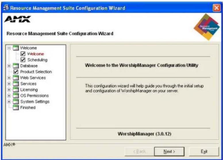
FIG. 1 RMS Configuration Wizard - Welcome screen
Click Next to begin the RMS Configuration Wizard.
Appointment Management/Scheduling System
The RMS server software can manage appointments using an Internal or External scheduler such as Microsoft Exchange or Lotus Notes (see the Scheduling System Plug-ins section on page 11). Depending on your configuration, additional configuration steps need to be taken.
| Appointment Management/Scheduling System | |
| • Internal Appointment Management/Schedule System: | Select this option if you want to use the Appointment Management features of RMS, but do not want to connect to an external scheduling system. |
| • External Appointment Management/Schedule System: | Select this option if you want to use the Appointment Management features of RMS with an external scheduling system. |
If you wish to use an existing scheduling system, choose the External Appointment Management/Scheduling System option. Otherwise, select Internal Appointment Management/Scheduling System (FIG. 2).
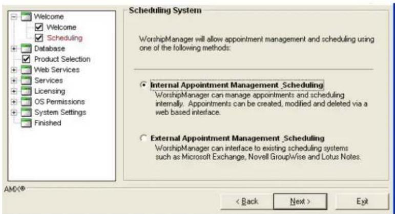
FIG. 2 RMS Configuration Wizard - Scheduling System

External scheduling interfaces may be obtained from an AMX dealer and installed separately. See the RMS Supported Scheduling and Mailbox Interfaces section on page 2.
Click Next to continue to Database.
Database
RMS uses a single central database for all data storage. This database can be configured in the RMS Configuration Wizard.

Please refer to the RMS Database Administrator's Guide (available to view/download from www.amx.com) for more details on RMS database installation and configuration.
Database - Connection
The next step is to verify the RMS database connection (FIG. 3):
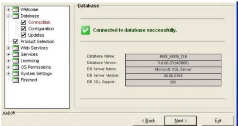
FIG. 3 RMS Configuration Wizard - Connection to Database
Database - Configuration

The Configuration screen may be skipped in the Configuration Wizard if a successful database connection is detected. You can navigate to the Configuration screen at any time by double-clicking the "Configuration" item in the navigation tree under the "Database" heading.
The Configuration screen allows you to manually configure the database connection settings (FIG. 4). You need to specify the database server name/address and the database/catalog name.
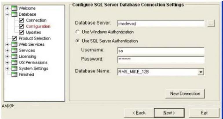
FIG. 4 RMS Configuration Wizard - Configuration
Click Next to proceed.
Database - Updates
The Database Updates screen indicates if the existing database needs to be updated (FIG. 5).
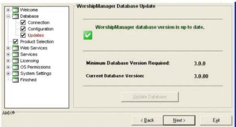
FIG. 5 RMS Configuration Wizard - Database Updates
If the database versions are mismatched, the Update Database button is available.
The Updates screen may be skipped in the Configuration Wizard if a successful database connection is detected and no updates are required. You can navigate to the Updates screen at any time by double-clicking the "Updates" item in the navigation tree under the "Database" heading.
Click the Update Database button to start the database update process
After the updates are complete, click Next to proceed to Product Selection.

Product Selection
RMS supports several vertical markets. Use the RMS Installation Type drop-down menu in the Product Selection screen (FIG. 6) to select one of the following branches of RMS to install as your server.
• MeetingManager - Presentation Facilities
• ClassroomManager - Education
• ExhibitManager - Retail and Museums
- VenueManager - Entertainment, Hotels, Healthcare, and Broadcasting
● WorshipManager - Houses of Worship
• IntelligentManager - Government
● HomeManager - Whole Homes, Home Theater, Multi-Dwelling Units, and Private Transportation
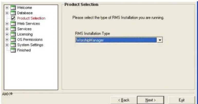
FIG. 6 RMS Configuration Wizard - Product Selection
Click Next to proceed to Web Services.
Web Services
RMS requires the use of the Microsoft IIS (Internet Information Services) to host the RMS web pages (ASP).

For details and configuration information on IIS, ASP.NET and the RMS Web Application, see the RMS IT Administrator's Guide (available at www.amx.com).
Web Services - Microsoft IIS Server
This step in the Configuration Wizard ensures that the IIS web server is running. If the IIS web server is not running, click Start IIS Web Server, on the Microsoft IIS Server screen (FIG. 7).
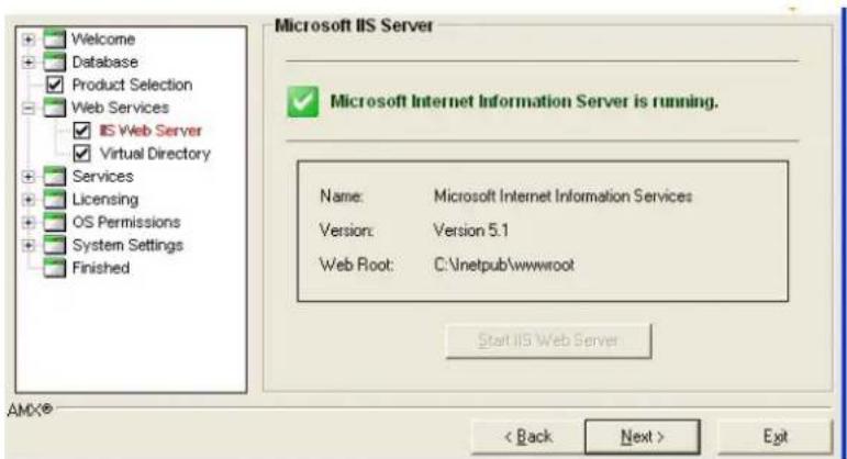
FIG. 7 RMS Configuration Wizard - Start Microsoft IIS Server
Click Next to continue.
Web Services - Virtual Directory
The RMS user interfaces are web pages designed to run in Windows IIS Server. This configuration step guides you through the proper setup of the IIS Virtual Directory.
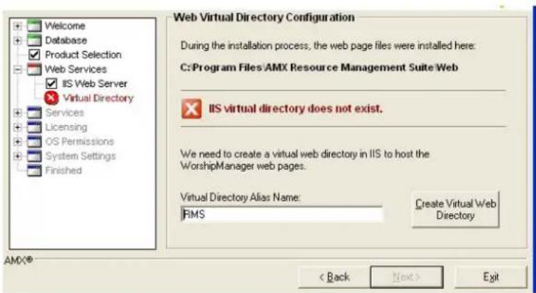
FIG. 8 RMS Configuration Wizard - Web Virtual Directory Configuration
| Web Virtual Directory Configuration (IIS) | |
| Virtual Directory Alias Name | Enter the name of the virtual directory you would like to use for the RMS web pages.The Configuration Wizard will make the appropriate changes to your IIS configuration when you click Create Virtual Web Directory. These include creating a virtual directory, creating an ASP application for this directory, and setting the "Enable Parent Paths" option to true. |
- Enter the name of the virtual directory used for the RMS web pages, in the Virtual Directory Alias Name field.
- Click Create Virtual Web Directory, the Configuration Wizard will make the appropriate changes to your IIS configuration.
- Click Next to proceed.
Services
The RMS server software is comprised of a collection of Windows NT Services.
- NT Services allow the program to load automatically on computer boot up and to run unattended without a user being logged onto the computer.
- NT Services must be registered with the Windows operating system.

For more details and configuration information on the RMS NT Services, please see the RMS IT Administrator's Guide (available to view/download from www.amx.com).
RMS services are compatible with Microsoft Windows 2003 and newer operating systems. You must register all services before proceeding to the next step.
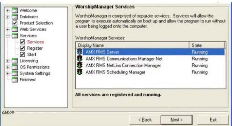
FIG. 9 RMS Configuration Wizard - RMS Application Suite Services
| Service Registration | |
| AMX RMS Server | This service is the primary RMS service. This service loads automatically upon Windows boot up. |
| AMX RMS Communications Manager | This service handles all outbound communication for the RMS system notifications and the following communication methods:• SMTP Email Messages• SYSLOG Messages• Windows Event Log Messages• SNPP Paging Messages• SNMP Trap MessagesThis service loads automatically upon Windows boot up. |
| AMX RMS NetLinx Manager | This service is responsible for hosting, facilitating, and maintaining all connections and communications with the NetLinx systems.This service loads automatically upon Windows boot up. |
| AMX RMS Scheduling Manager | This service connects to external scheduling systems (Microsoft Exchange, Lotus Notes, etc.) and acquires appointments for a given calendar folder for each room configured in the RMS system.Upon clicking the "Register Services" button, you are prompted to choose between the system account and a local user account if you are connecting to an external scheduling system.If you are planning on integrating the room scheduling and appointment features of the RMS with an external messaging system you must configure this service to log on as a user or resource account that has Domain permissions to the target messaging system mailbox/calendar or local MAPI profile.This service loads automatically upon Windows boot up. |
Click Next to continue.
Services - Register
Initially, the RMS services are not registered. Click the Register Services button to start the registration process (FIG. 10).
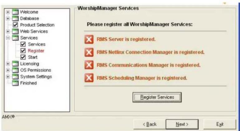
FIG. 10 RMS Configuration Wizard - Register RMS Application Suite Services
If the External Appointment Management/Scheduling System option was selected in the Appointment Management/Scheduling System step, the service registration prompts you to select a user account which the scheduling service will utilize for appointment access functions. This is important for some scheduling systems where specific user accounts require domain user security privileges.
For example, to access a Microsoft Exchange account, the scheduling service must log on with a user account that has access to all of the desired Exchange mailboxes.
If your third-party scheduling system does not require domain user permissions, you can use the Local System account option.
Please review the documentation covering the particular RMS Scheduling Plug-in that you intend to use.
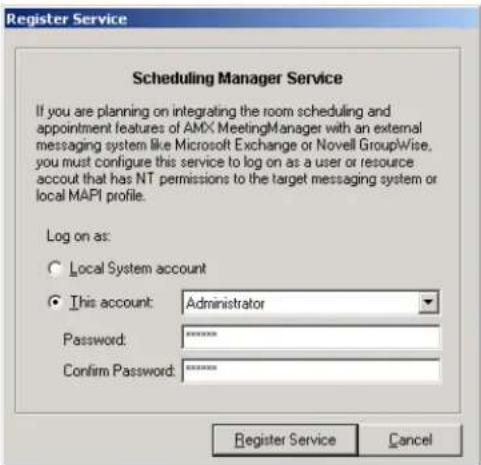
FIG. 11 Scheduling Manager Service
After making your selection, click Register Service to continue.
After completing the registration process, the Configuration Wizard indicates all RMS services were registered successfully.
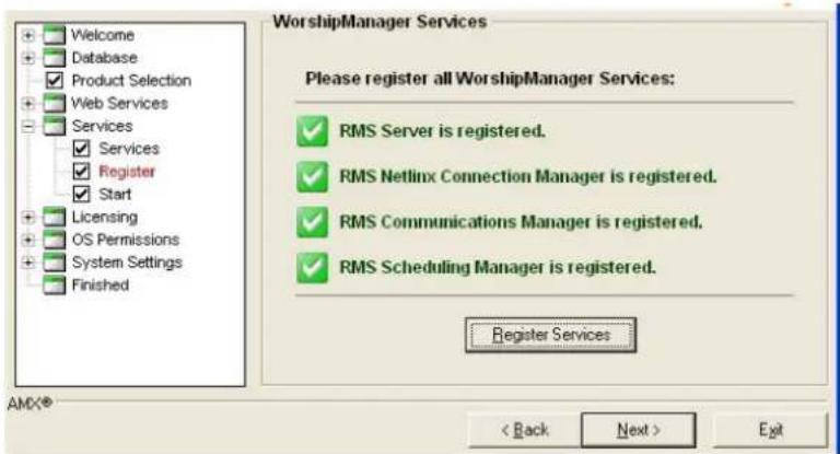
FIG. 12 RMS Configuration Wizard - RMS Application Suite Services Successfully Registered Click Next to continue.
Services - Start
After the RMS services have been registered, you must start them.
Click the Start Services button on the Start Services screen (FIG. 13).
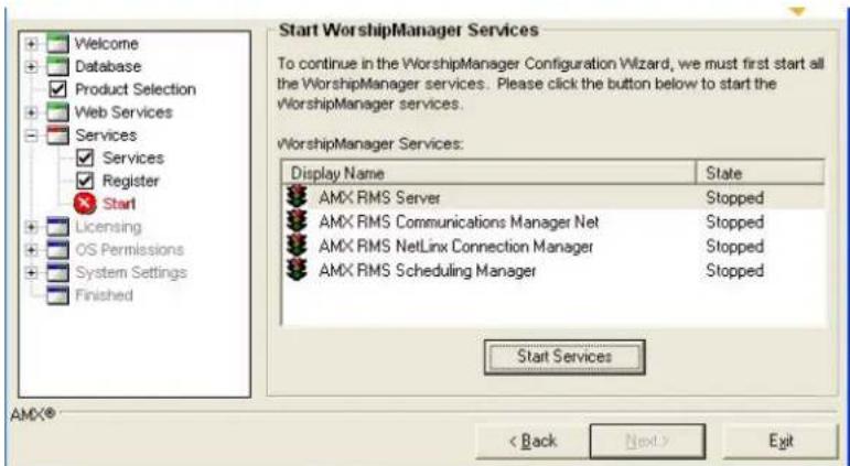
FIG. 13 RMS Configuration Wizard - Start RMS Application Suite Services
As the Configuration Wizard is starting each service, a dialog indicates the startup status (FIG. 14). Click Cancel to cease starting services and return to the Configuration Wizard.
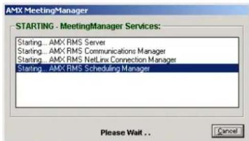
FIG. 14 Starting Services Dialog
Upon the successful start of the RMS services, the Configuration Wizard visually indicates all services as Running (FIG. 15).
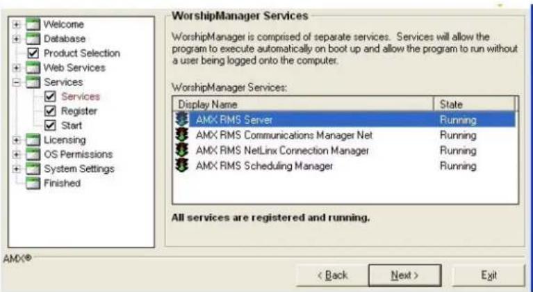
FIG. 15 RMS Configuration Wizard - RMS Application Suite Services Running
Click Next to proceed.

The AMX RMS Server service is the primary service. All other services depend on this service; therefore it must always be started first and stopped last. The Windows Services manager and the RMS Service Manager Utility will not allow you to stop this service until all other services have been stopped. When starting one of the other services first, the Windows Services manager and the RMS Service Manager Utility will start the RMS Server service first.
Licensing
RMS requires a Server serial number, and the appropriate client licenses to provide either Asset management or Scheduling functions as desired (FIG. 16).
If the number of NetLinx connected systems is greater than the number of licenses available you can still track them in the Unassigned NetLinx Systems section of the HotList. You will need more Client Licenses before you can create rooms for these systems.
The RMS application can run without a license key. In Standard mode, you can run the RMS application with limited capabilities for previewing the functionality of the software:
- No rooms without masters
- No control function macro creation, scheduling, or execution
- No external scheduling
- Only 1 user other than admin
- Standard mode management limited to five rooms
• Only one notification recipient
Licensing Summary - Asset Licenses vs. Scheduling License
The following table provides a summary of features that are "enabled" with each license type:
| Asset Licenses vs. Scheduling License | ||
| Feature Asset License Scheduling License | ||
| Allows the reservation of a room via Touch Panel. | √ | |
| Allows the display of a room's schedule via Touch Panel. | √ | |
| Allows reservation of a room via third-party scheduling system or RMS scheduling engine. Note: Separate plug-in required when using third-party scheduling system. | √ | |
| Allows scheduling of presets for a meeting via third-party scheduling system or RMS scheduling engine. This requires both an Asset and a Scheduling license. Note: Separate plug-in required when using third-party scheduling system. | √ | √ |
| Allows creation of presets, executable via the RMS web interface. | √ | |
| Allows scheduling of presets via the RMS web interface. | √ | |
| Allows display of a device's status (on/off, error, etc.) via the RMS web interface. | √ | |
| Allows triggering of notifications based on device status. | √ | |
| Allows for end-users to send help requests. | √ | |
Licensing - Server Licenses
To obtain RMS licensing, contact AMX at:
• AMX Global Customer Service - 800-222-0193
• service@amx.com
or contact your AMX dealer.
![Welcome Database Product Selection Web Services Services Licensing Server Licenses Client Licenses OS Permissions System Settings Finished Licensing WorshipManager requires a server license and additional client licenses for each independent room or reporting location in the system. Server license key detected. Server is licensed. Software Serial Number: B00217A0635244008 Edit Server License Information [Serial Number should be with your RMS CD, if not please contact AMX.] AMX® < Back Next > Exit](/content/2026/06/1185428/images/8675a22bfa1fd6614a9c118af9c4f4289221fa83bfd734c07eb8fd4f95a7bdd0.jpg)
FIG. 16 RMS Configuration Wizard - Server License Detected
Click Next to continue.

If you do not have a RMS license key and you opted to operate in Standard mode, the Configuration Wizard indicates the key was not detected and the Software Serial Number reads: Standard Edition.
Click Next to continue.
Enter Server Serial Number
The Enter Server Serial Number window (FIG. 17) allows you to set the RMS server serial number, company name and contact information. The Manual Authorization button allows you to authorize your RMS server without connecting to AMX.
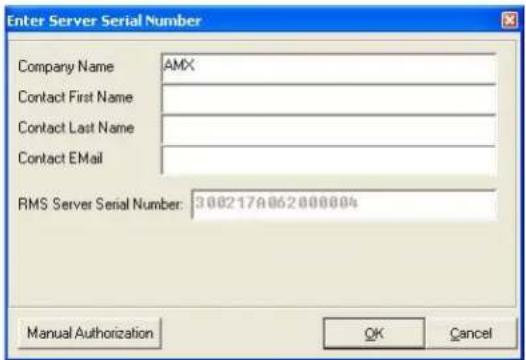
FIG. 17 Enter Server Serial Number
Manual Authorization
The Manual Authorization window (FIG. 18) allows you to finalize your server authorization without a connection to AMX.
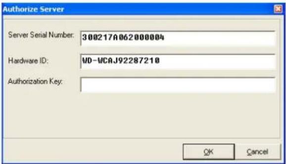
FIG. 18 Manual Authorization
- Server Serial Number - The number for your RMS server software installation.
- Hardware ID - This number is taken from the server.
- Authorization Key - This number can be provided by AMX when a proper connection cannot be made.
Manually Authorizing Your RMS Server
If your RMS server cannot connect to AMX for authorization, follow these steps:
- Contact AMX at one of the following to obtain an Authorization Key:
● AMX Global Customer Service at 800-222-0193
• by email at service@amx.com or
- contact your AMX dealer.
-
In the Licensing - Server Licenses section on page 24, click Edit Server License Information. The Enter Server Serial Number dialog box opens.
-
Click the Manual Authorization button. The Manual Authorization dialog box opens.
- Type the AMX provided authorization key in the field provided and click OK.
Licensing - Client Licenses
RMS requires additional Client Licenses. Additional Client Licenses can be entered now, or at any time in the RMS Configuration Wizard.
To obtain RMS Client Licensing, contact AMX at:
- Contact AMX Global Customer Service at 800-222-0193
• by email at service@amx.com or - contact your AMX dealer.
If you have a licensed RMS Premium edition with a software serial number, the Configuration Wizard displays the Software Serial Number and allows you to add or remove Client Licenses (FIG. 19).
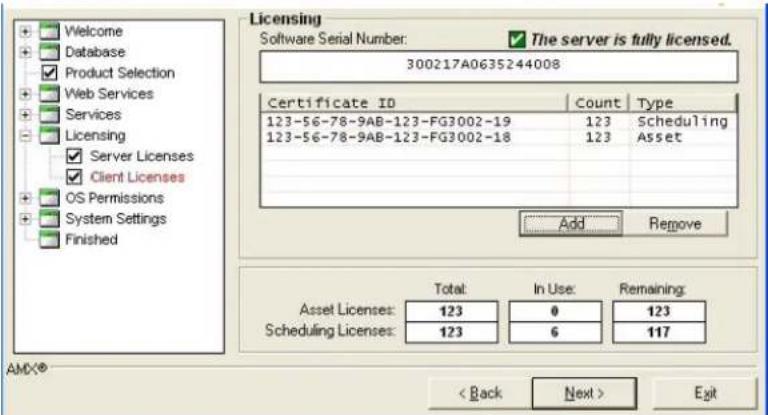
FIG. 19 RMS Configuration Wizard - Client Licenses
- To remove a client license, click on it and select Remove.
- Click Add to enter additional client licenses.
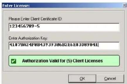
FIG. 20 Add Client License
- Enter the Client License Certificate ID and the Authorization Key in the appropriate fields.
- Click OK to complete the client license entry.
If you do not wish to enter additional client licenses, click Next to continue.
If you do not have a RMS license key installed and you opted to operate in Standard mode, the Configuration Wizard indicates the key was not detected and the Software Serial Number reads: Standard Edition.
Click Next to continue.
OS Permissions
Certain NTFS and registry access permissions may be required by the AMX RMS Scheduling Manager service to access resources on the RMS server.

For more details and configuration information on NTFS, ASP.NET, IIS and DCOM permissions, please see the RMS IT Administrator's Guide (available to view/download from www.amx.com).
OS Permissions - Service User
The Configuration Wizard automatically creates the appropriate NTFS and registry access permissions for the service user account.
Below is a list of files and directories that require special permissions:
| Web NTFS Permissions | |
| RMS Registry Access | The RMS Scheduling Manager service user account must have read and write registry access permissions to the registry key:HKEY_LOCAL_MACHINE\SOFTWARE\AMX Corp.\RMS |
If the External Appointment Management/Scheduling System option was not selected on the Appointment Management/Scheduling System step, or the scheduling service was registered with a the Local System user account, then no permissions need to be configured (FIG. 21).
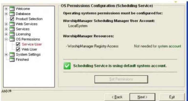
FIG. 21 RMS Configuration Wizard - OS Permissions Configuration (Scheduling Service) No Permissions Needed
Click Next to continue.
If the External Appointment Management/Scheduling System option was selected on the Appointment Management/Scheduling System step, and the scheduling service was registered with a user account other than the Local System account, then the Configuration Wizard ensures the scheduling server user account has all of the appropriate NTFS directory permissions and registry access permissions required to allow the scheduling service to interact with the system.
- Click Set Permissions to begin.
- Once the Configuration Wizard has completed setting all of the appropriate system permissions, it will indicate Permissions Are Set.
- Click Next to continue.
OS Permissions - Web User

This screen may be skipped if your servers' file system is formatted as a FAT or FAT32 file system. These file systems do not support security options so this step is not required.
Certain NTFS permissions are required for the users of the web pages to access resources on the RMS server. The Configuration Wizard automatically creates the appropriate NTFS permissions for the web users.
Below is a list of files and directories that require special permissions:
| Web NTFS Permissions | |
| • Temporary files directory | The web users must have read and write access to the temporary files directory. |
| • Dynamic Images Directory The web users must have read and write access to the dynamic images directory. | |
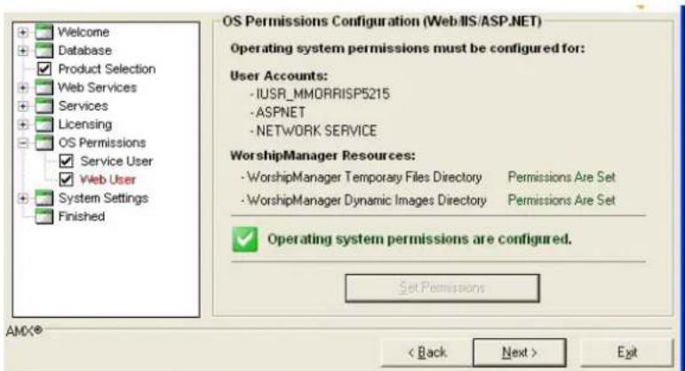
FIG. 22 RMS Configuration Wizard - OS Permissions Configuration (Web User)
- To set the appropriate permissions, click Set Permissions.
- Once the Configuration Wizard has completed setting all of the appropriate system permissions, it will indicate Permissions Are Set.
- Click Next to continue.
System Settings
In the System Settings section, the Configuration Wizard configures application-specific setting and options.
System Settings - NetLinx
The first step in the System Settings section is NetLinx Server Settings (FIG. 23).
All NetLinx systems must connect to the RMS server over a TCP/IP connection. In this step you can modify the IP Server Port that the NetLinx systems use to establish a connection and facilitate communication.
RMS uses IP port 3839 by default.
![OS Permissions System Settings ✓ NetLinx ✓ Security ✓ Administrator ✓ Scheduling ✓ Appointments ✓ SMTP ✓ SNMP ✓ Logging ✓ Syslog ✓ Reporting ✓ Time Sync ✓ Name & Logo Finished NetLinx Server Settings TCP/IP Server Port: 3839 [Default: 3839] This is the TCP/IP port that the NetLinx systems will use to connect to the WorshipManager server. Ping Delay Time: 30 [Default: 30 seconds] The ping delay time is the time between ping requests to connected NetLinx systems. Ping Timeout Time: 60 [Default: 60 seconds] NetLinx systems that do not respond to the ping request within the Ping Timeout Time, will be disconnected. < Back Next > Exit](/content/2026/06/1185428/images/96617023708ca6cd82a151361265021f3ab938cdef6aaf1de5125305d098a654.jpg)
FIG. 23 RMS Configuration Wizard - NetLinx Server Settings
NetLinx Server Settings
| • TCP/IP Server Port | This field configures the IP port on which the RMS server accepts connections from NetLinx masters.The default port is 3839, which is a IANA register port for RMS communications.If you are upgrading from a version 1.0 of RMS, you may wish to use port 9090.The RMS 2.0 server is fully backwards compatible with the RMS 1.0 NetLinx clients; however they will not take advantage of the new features and optimizations of 2.0. If this value is changed from one of the defaults, this new value must be configured in each NetLinx system using the 'SERVER-' command. |
| • Ping Delay Time | The ping delay time is used to ensure that NetLinx clients are connected to the RMS server. On this configured time interval, the RMS server broadcasts request messages to the NetLinx clients.If the NetLinx clients do not respond within a specified amount of time, the RMS server assumes the connection has been lost and the NetLinx system is offline. |
| • Ping Timeout Time | The ping timeout time setting is used as the maximum amount of time the RMS server allows between NetLinx client ping responses.If the NetLinx client does not return a ping response within this amount of time, the RMS server assumes the connection has been lost and the NetLinx system is offline. |
After completing these settings, click Next to continue.
System Settings - Security
Use the options in the Security Settings screen to determine if you want to require user authentication to access the RMS administrative web interface (FIG. 24).
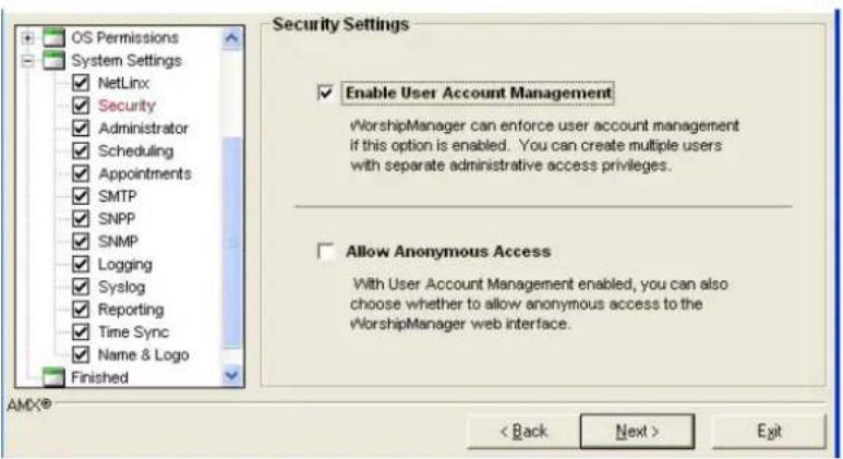
FIG. 24 RMS Configuration Wizard - Security Settings
- If you want user authentication, check the Enable User Account Management option. If the Enable User Account Management option is checked, you can also choose to allow anonymous access to view the RMS administrative web interface.
- To enable anonymous access, check the Allow Anonymous Access option.

If using Integrated Windows Authentication, you can not enable anonymous access.
Click Next to continue.
System Settings - Administrator
If User Account Management is enabled, the Configuration Wizard automatically configures the default administrator account. The default administrator user name is Admin. Enter the desired default administrator password in the text fields provided in the Administrator Account screen (FIG. 25).
![OS Permissions System Settings NetLinx Security Administrator Scheduling Appointments SMTP SNPP SNMP Logging Syslog Reporting Time Sync Name & Logo Finished Administrator Account The Administrator account is not configured. Please enter the new Administrator account password: Administrator Username: admin Administrator Password: Confirm Password: [Be sure to record the Administrator username and password. This information will be needed later to configure WorshipManager.] AMX® < Back Next > Exit](/content/2026/06/1185428/images/680b7318ffdae6c04f3f68969e95fce96bb472e6b3eb8c8145443f38620a05cc.jpg)
FIG. 25 RMS Configuration Wizard - Administrator Account

This screen may be skipped if you choose not to enable User Account Management.
It is important to record this administrator username and password in a safe location.
Once the default administrator account has been established, you cannot return to this step to alter it.
If the default administrator account has already been configured and you return to this step, the Configuration Wizard indicates The Administrator account has already been configured and does not allow you to alter the account.
Click Next to continue.
System Settings - Scheduling
If the Internal Appointment Management/Scheduling System option was selected on the Appointment Management/Scheduling System step, then you will only need to enter a default Master Appointment Password in the Internal Scheduling System Options screen (FIG. 26).
| Appointment Modification Master Password | |
| Master Appointment Password | This password is used to gain access to any user created appointment record in the system.Type a password in the field provided.If this password is blank, there is no master password for modifying appointments.The default password is 1988. |
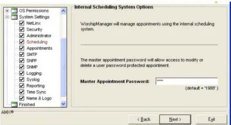
FIG. 26 RMS Configuration Wizard - Master Appointment Password Modification
Click Next to continue.
If the External Appointment Management/Scheduling System option was selected on the Appointment Management/Scheduling System step, then you need to configure which Scheduling Plug-in interface you wish to use with the RMS (FIG. 26).
For specific details on each Scheduling Plug-in, see the documentation that is associated with that plug-in. After you have selected and registered the desired Scheduling Plug-in, click Next to continue.
System Settings - Appointments
If the Internal Appointment Management/Scheduling System option was selected on the Appointment Management/Scheduling System step, you are presented with the Appointment Options screen (FIG. 27).
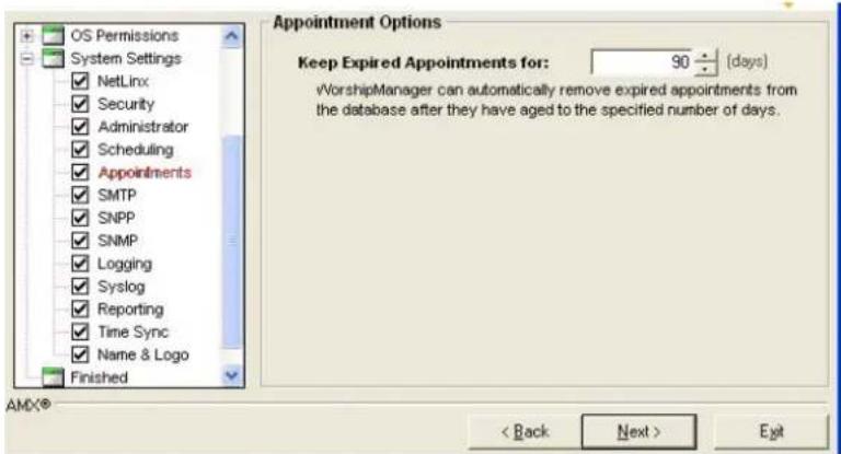
FIG. 27 RMS Configuration Wizard - Internal Appointment Options
| Internal Appointment Options | |
| • Keep Expired Appointments For | After appointments have expired, RMS automatically remove them from the system after this elapsed time.The default setting is 90 days. |
Click Next to continue.
If the External Appointment Management/Scheduling System option was selected on the Appointment Management/Scheduling System step, then you are presented with the Appointment Options screen shown in FIG. 28.
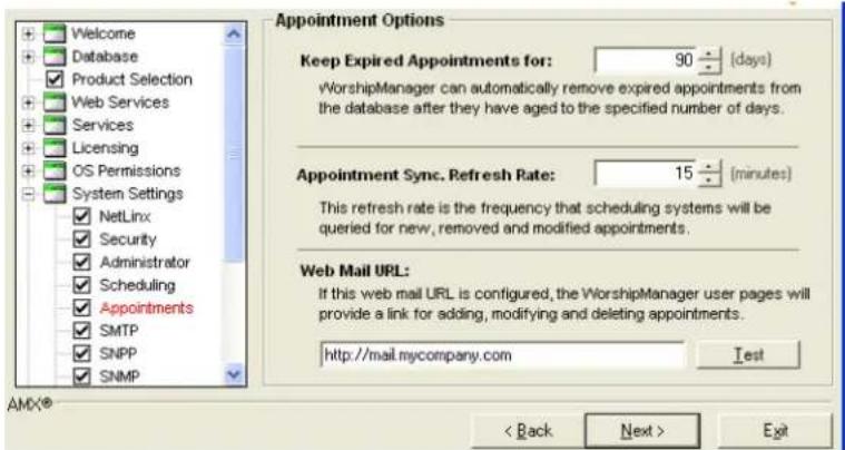
FIG. 28 RMS Configuration Wizard - External Appointment Options
| External Appointment Options | |
| • Keep Expired Appointments For | After appointments have expired, RMS automatically removes them from the system after this elapsed time.The default setting is 90 days. |
| • Appointment Synchronization Refresh Rate | The RMS scheduling service attempts to connect to your third-party scheduling system at this time interval to update all new, modified, and deleted appointment records.The default setting is 15 minutes. |
| • Web Mail URL | If your third-party scheduling system has a web based interface, you should enter the web path in the web mail URL field. If your third-party scheduling system does not have a web based interface, make sure this field is empty.After entering the web path, you can click the Test button to verify the path. |
After completing these settings, click Next to continue.
System Settings - SMTP
SMTP (Simple Mail Transport Protocol) is the standard for sending email on the Internet. RMS uses SMTP for sending email notifications to users. Enter all the appropriate SMTP settings in the SMTP Email System screen (FIG. 29).
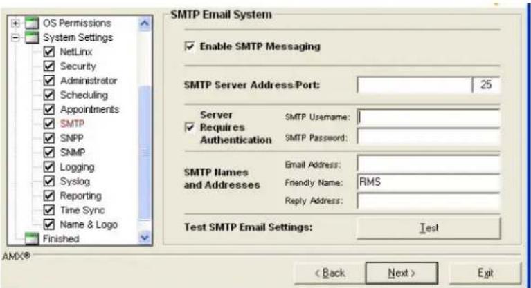
FIG. 29 RMS Configuration Wizard - SMTP Email System
| SMTP Settings | |
| • SMTP Enabled C | check this item to enable SMTP email delivery. |
| • Server Enter the IP | address or host name of the SMTP server.IP port 25 is used for all SMTP communications. |
| • Server Required Authentication | Check this item if your SMTP server requires a username and password authentication. |
| • Username Enter a valid username on the SMTP server. | |
| • Password Enter the password for the username on the SMTP server. | |
| • Email Address Enter an email address from which all RMS notifications will be sent (100 characters max). | |
| • Reply Email Address | Enter the reply-to email address.Typically this is the same as the Email Address. |
| • Friendly Name | Enter the display name you want to appear as the sender for notification emails. |
You can test these SMTP setting using the Test button:
- Press the Test button, to access the SMTP Test dialog (FIG. 30).
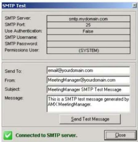
FIG. 30 SMTP Test
- Enter the email address you wish to send the test message.
You can optionally modify the subject and message to send.
-
When ready, press the Send Test Message button to send the text message.
-
When you have competed testing, click Close.
Click Next to continue.
System Settings - SNPP
SNPP (Simple Network Paging Protocol) is an alternative method to SMTP for delivering text-based messages to alphanumeric pager and cellular phones.
If your wireless provider supports SNPP messaging, RMS can send notifications messages to users using SNPP. SNPP is preferred over the standard SMTP method of delivering text messages to wireless devices, as it is more direct and efficient (FIG. 31).
Enter all the appropriate SNPP settings in the SNPP Paging screen (FIG. 31).
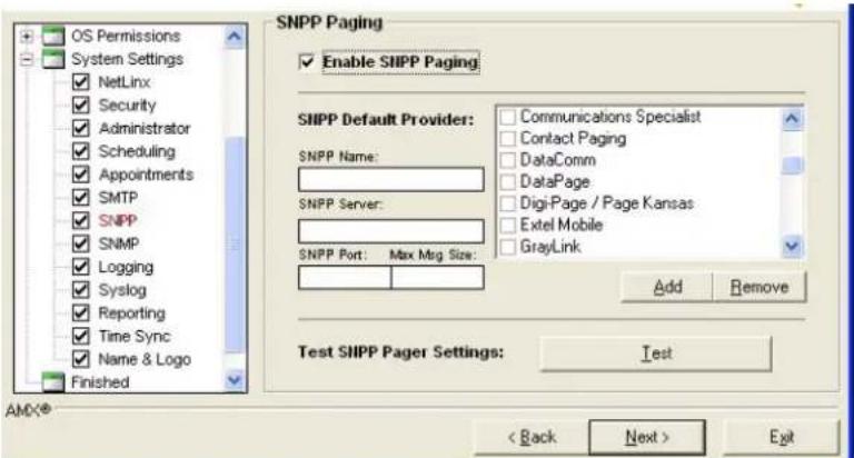
FIG. 31 RMS Configuration Wizard - SNPP Paging
| SNPP Settings | |
| • Enable SNPP Paging Place a check in the box to enable SNPP Paging. | |
| • SNPP Default Provider Make a selection from the list. | |
| • Add | If your SNPP provider is not in the provider list, you can add additional providers. |
| • Remove Remove an SNPP provider from the list. | |
If you wish to use SNPP paging, check the Enable SNPP Paging option and select a default SNPP provider from the provider list. If your SNPP provider is not in the provider list, you can add additional providers using the Add button.
You can test these SNPP settings using the Test button:
-
If you press the Test button, the SNPP Pager Test dialog will appear (FIG. 32).
-
Enter the pager ID for the mobile device you wish to send the test message. You can optionally modify the text message to send.
-
When ready, press the Send Test Message button to send the text message.
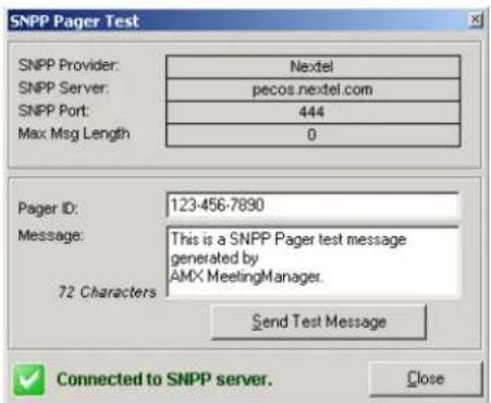
FIG. 32 SNPP Pager Test dialog
When you have completed testing, click Close.
Click Next to continue.
System Settings - SNMP
SNMP is the network management protocol used almost exclusively in TCP/IP networks. SNMP provides a means to monitor rooms, systems, and devices in the RMS system.
Enter all the appropriate SNMP settings in the SNMP Services screen (FIG. 33).
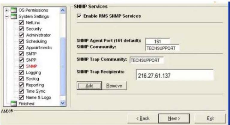
FIG. 33 RMS Configuration Wizard - SNMP Service
| SNMP Settings | |
| • Enable RMS SNMP Services | Place a check in the box to enable SNMP Services. |
| • SNMP Agent Port (161 default) | Type the port number to use for SNMP. |
| • SNMP Community The group to which devices and management stations running SNMP belong.This field is usually a "friendly" name. | |
| • SNMP Trap Community | An alert that is sent to a management station by agents.This field is usually a "friendly" name. |
| • SNMP Trap Recipients | The name or IP address of hosts to which traps are to be sent.This is the management station, either a DNS name or IP address. |
| • Add Adds a new recipient. | |
| • Remove Removes selected recipient. | |
System Settings - RFID Tracking
RMS can track RFID devices. This option can be enabled or disabled via options in the RFID Tracking Options screen (FIG. 34).
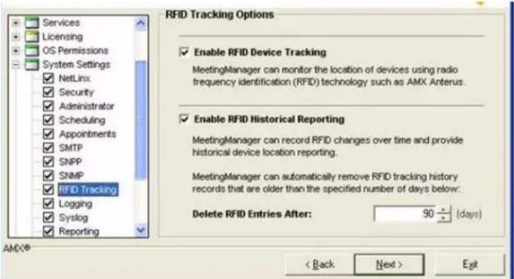
FIG. 34 RMS Configuration Wizard - RFID Tracking Options
| RFID Tracking Options | |
| · Enable RFID Device Tracking | Enables you to globally enable or disable RFID tracking.The default setting is Enabled. |
| · Enable RFID Historical Reporting | Enables you to indicate whether you want to keep historical records and display RFID history reports.The default setting is Enabled. |
| · Delete RFID Entries After | Enables you to indicate how long, in days, you want to keep historical RFID records.The default setting is 90 days. |
Click Next to continue.
System Settings - Logging
RMS can record room device and parameter changes to an internal database log as well as the Windows event log. Specify logging preferences in the Logging Options screen (FIG. 35).
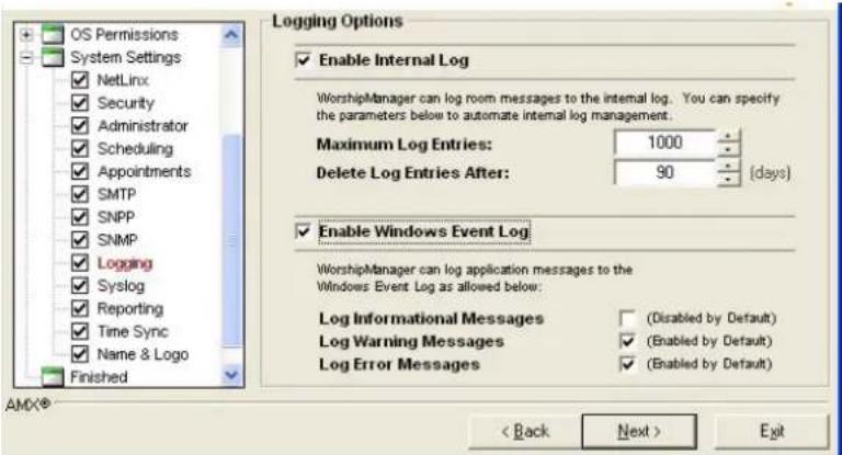
FIG. 35 RMS Configuration Wizard - Logging Options
| Logging Options | |
| • Enable Internal Log $ | Select this option to enable internal logging. |
| • Maximum Log Entries | Enter the number of messages.If you would rather base the Internal Log size on dates of messages, set this value to 0 and set Delete Log Entries After. |
| Logging Options (Cont.) | |
| • Delete Log Entries After | Enter the number of days.If you would rather base the internal log size on number of messages, set this value to 0 and set Keep Maximum Log Entries. |
| • Enable Windows Event Log | Select this option to enable event logging. |
| • Log Informational Messages | If this option is selected, the RMS server logs all informational type messages to the windows event log.It is not recommended to use this option, if a large number of messages are posted to the event log. |
| • Log Warning Messages | If this option is selected, the RMS server logs all warning type messages to the windows event log.It is recommended to use this option to record any warning level notifications. |
| • Log Error Messages | If this option is selected, the RMS server logs all error type messages to the windows event log.It is recommended to use this option to record any error level notifications. |
Click Next to continue.
System Settings - Syslog
SYSLOG logging can also be used to log messages. You need to supply the Syslog Server IP Address or hostname and the Syslog IP Port to enable communication in the SYSLOG Options screen (FIG. 36).
The default SYSLOG IP port is 514 and does not need to be changed unless you have a custom Syslog configuration.
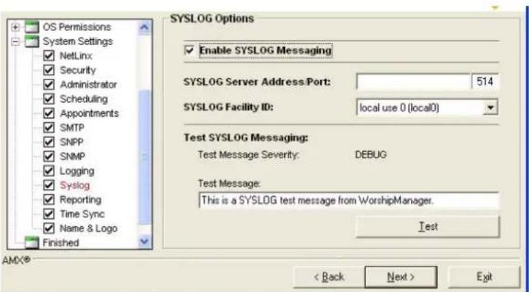
FIG. 36 RMS Configuration Wizard - SYSLOG Options
| SYSLOG Options | |
| • Enable SYSLOG Messaging | Select the Enable SYSLOG Messaging to enable Syslog messages. |
| • Syslog Server Address/Port | Enter the IP address or host name for the Syslog server.Enter the IP port for the Syslog server. |
| • Syslog Facility ID | Select the facility from the drop down list. |
| • Test Message Severity | Select from the drop-down list the message level severity. |
| • Test Message Text | field for the message to be sent. |
You can test SYSLOG messages by setting some sample text in the Test Message Severity field, and clicking the Test button.
Click Next to continue.
System Settings - Reporting
RMS can provide detailed reporting on room device and parameter changes based on a tracked history. Specify reporting preferences in the Reporting Options screen (FIG. 37).
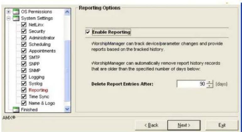
FIG. 37 RMS Configuration Wizard - Reporting Options
Place a check next to Enable Reporting to allow for this function.
You must also specify the number of days for RMS to track.
The default is 90 days.

The larger the number of days, the greater the number of records the database needs to store and the longer report queries take to run.
Click Next to continue.
System Settings - Time Sync
RMS can maintain time and date synchronization between the RMS server and the remote NetLinx systems. Set synchronization preferences in the Time Synchronization screen (FIG. 38).
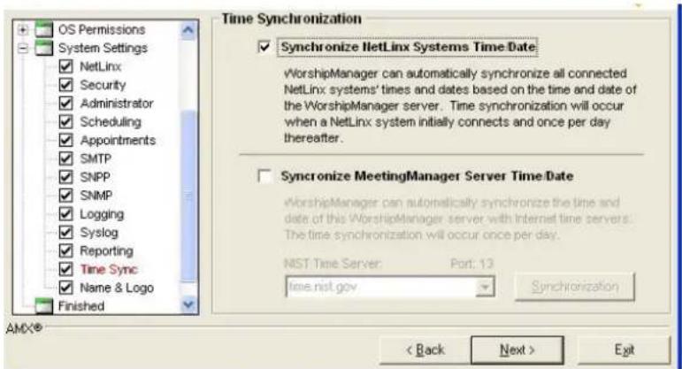
FIG. 38 RMS Configuration Wizard - Time Synchronization
- Synchronize NetLinx System Time/Date: if this option is enabled, the RMS server synchronizes the time and date on NetLinx systems upon connection and subsequently once each evening. This option is recommended to maintain a consistent time and date throughout the system.
- Synchronize Server Time/Date: if this option is enabled, the RMS server connects to an Internet time synchronization server once per evening and synchronizes the server local time and date. This option is recommended only if the server is not already synchronized by other means such as a network time synchronization program.
When selecting this option you can select a NIST time server from the NIST Time Server dropdown list or type in your own NIST time server address.
You can click the Synchronization button to test the time synchronization process.
Click Next to continue.
Name & Logo
RMS allows user customization of the web page title and web page logo graphic, via options in the System Name and Logo screen (FIG. 39). To change the web page title, enter the desired name in the Application Title field.
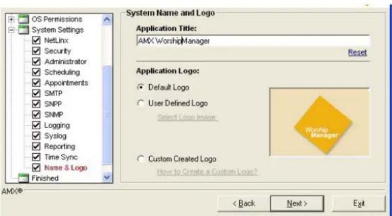
FIG. 39 RMS Configuration Wizard - Name & Logo
Select one of the logo options below to customize the web page logo:
- Default Logo - If this option is selected, the RMS uses the default logo graphic.
- User Defined Logo - If this option is selected, you can browse to select an image file of your choice.
- Custom Created Logo - If this option is selected, RMS uses a custom implemented logo image. This option provides the user a method to create a logo image that seamlessly matches the graphic style of the web pages without the need for a border or background color. For more information, please click the How to Create Custom Logo? link on this page of the Configuration Wizard.
Creating A Custom Logo
-
Open the "logo_custom.GIF" in your favorite graphics manipulation software.
-
This file can be found in the "C:\Program Files\AMX Resource Management Suite\Web\App_Themes\MeetingManagerImages" directory (if you used the default installation location).

The pixel dimensions for the logo are 147x101.
-
Add the logo to the image.
-
Save the logo to: "C:\Program Files\AMX Resource Management Suite\Web\App_Themes\MeetingManager\images" Make sure you save it as a.gif file and retain the name "logo_custom.GIF".
-
Use the Configuration Wizard to select "Custom Created Logo".
Finished
Congratulations you have completed the Configuration Wizard (FIG. 40).
You can return to the Configuration Wizard at any time to update or modify RMS settings.
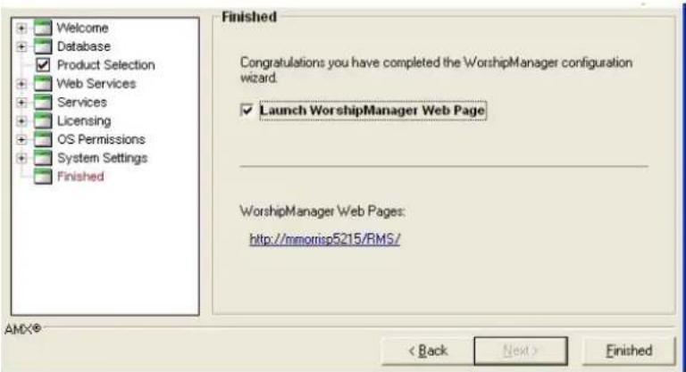
FIG. 40 RMS Configuration Wizard - Finished
Now that the RMS server is fully configured, the administrative web pages are ready to use and the server is ready to accept NetLinx connections.
If the Launch RMS application suite Admin Web Page option is selected, after closing the Configuration Wizard, the administrative web pages are automatically loaded.
You now need to add users (see the Creating a New User section on page 84), add rooms (see the Creating a New Room section on page 81) and create notifications (see the Creating a Notification section on page 90).
Database Wizard
Overview
RMS includes a utility program called the Database Wizard. The Database Wizard tool performs the following:
● Tests the RMS application database connection.
- Modifies the RMS application database connection settings.
- Creates new RMS application databases.
- Removes RMS application databases.
- Imports data to an RMS application database.
● Exports data from an RMS application database.
- Backs up an RMS application database.
- Converts the RMS application database to another database platform.
- Applies updates to the RMS application database.
During installation, the Database Wizard is used to create the RMS database.

NOTE
For more details on installing and configuring the RMS database, please see the RMS Database Administrator's Guide (available to view/download from www.amx.com).
Starting the Database Wizard
To access and perform the Database Wizard tasks, the RMS application services must first be stopped. If one of more of the RMS services are running when the Database Wizard starts, it will prompt you to stop the services before continuing.
- Click the Stop Services button and wait for all the services to stop.
- Click Next to continue.
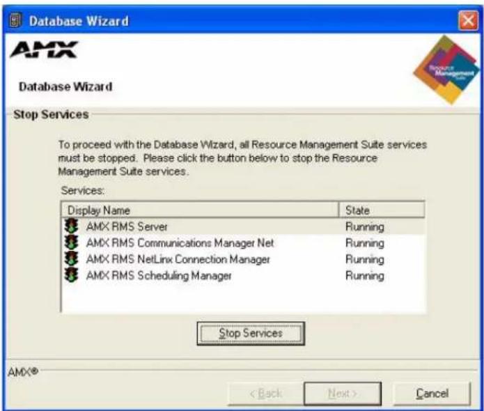
FIG. 41 Stop Services
First, the Database Wizard checks the existing RMS application database connection.
If a connection error is detected, you are prompted to re-configure the database connection settings (see the Configuring Connection Settings section on page 50).
Otherwise, click Next to continue to the main menu.
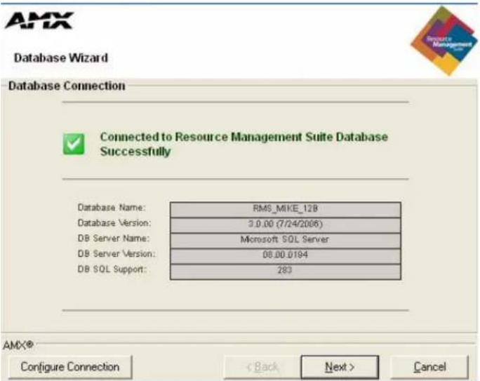
FIG. 42 Database Connection
Main Menu
The Database Wizard main menu (Menu Options screen) allows you to select the desired database operation to perform.
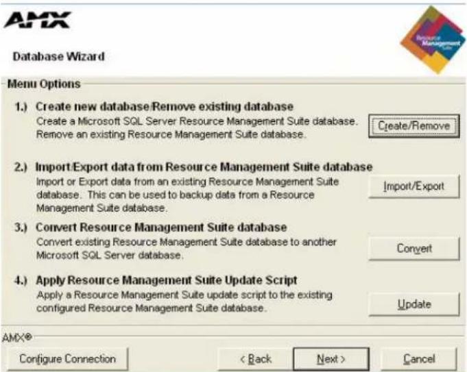
FIG. 43 Menu Options
- Create new database / Remove existing database
Select this option to create a new RMS application database or to remove an existing RMS application database. - Import / Export data from MeetingManager database
Select this option to import data into or to export data from the configured RMS application database. You can use the export option to backup the data in your RMS application database.

The export function of the Database Wizard should not be used as a replacement for standard network and systems backup procedures typically performed by an IT department, but rather in addition to standard backup procedures. The export function creates a snapshot of the data contents in the RMS database, but does not backup the database file nor the database server.
3. Convert RMS Database
Select this option to convert the currently configured database to an alternate database platform. This option automates the process of creating a new database on the Microsoft SQL Server, migrating the data from the existing database to the new database, and re-configuring the RMS application's connection settings to use this new database.
4. Apply RMS Update Script
Select this option if you have a database update script that you need to apply to your database. Database update scripts are created by AMX to provide a means of updating the existing database in place.
Configure Connection
Select this button to re-configure the RMS database connection settings.
Create / Remove
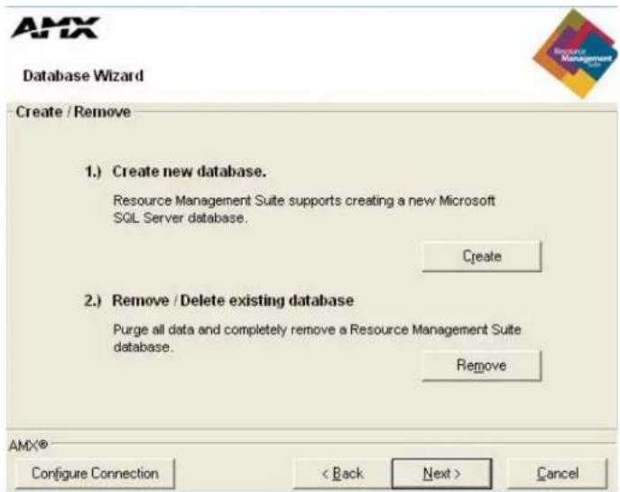
FIG. 44 Create / Remove
1. Create new database.
Select this option to create a new RMS application database.
2. Remove / Delete existing database.
Select this option to delete an RMS application database file or remove an RMS application database from a database server.
Import / Export
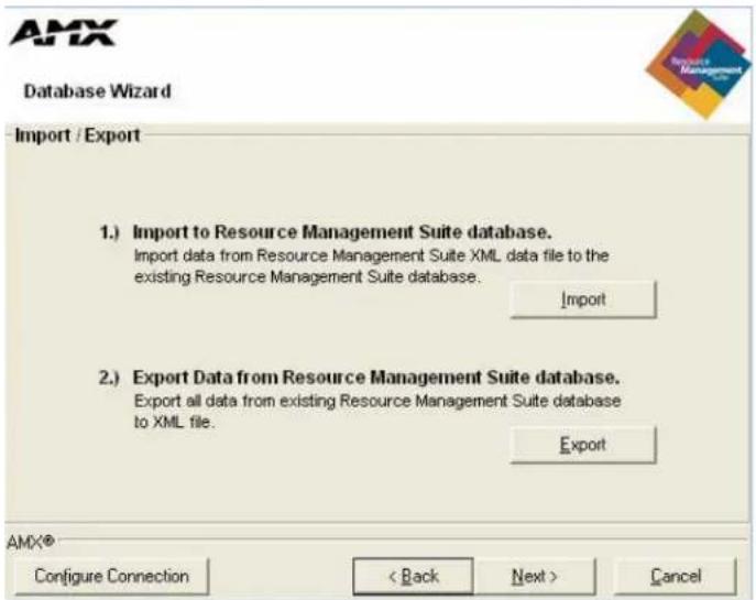
FIG. 45 Import / Export
1. Import to RMS database.
Select this option to import data into the configured RMS application database.
2. Export Data from RMS database.
Select this option to export data from the configured RMS application database. You can use the export option to backup the data in your RMS application database.
Create A New Database
The Database Wizard can create a new RMS application database for the following database platforms:
• Microsoft SQL Server 2005
You will need to provide the following information in the Create Microsoft SQL Database screen (FIG. 46):
• Microsoft SQL Server Address
- Use Windows Authentication or
• Use SQL Server Authentication
• Microsoft SQL Server Username
• Microsoft SQL Server Password
• RMS application Database Name
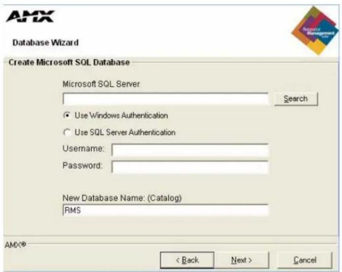
FIG. 46 Create Microsoft SQL Database
Click Next to begin creating the new database.
The Database Wizard creates the database structure of tables, then imports all of the default data into the new database.
When the processes have completed, the Database Wizard automatically reconfigures the RMS application connection settings to point to this new database.
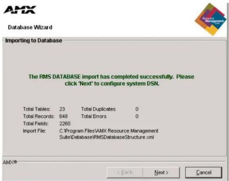
FIG. 47 Importing Database Completed
Click Next to continue.
The Database Wizard performs a database connection test and then returns to the main menu.
Remove A Database
The Database Wizard can remove an existing RMS application database for the following database platforms:
• Microsoft SQL Server 2005
You need to provide the following information:
- Microsoft SQL Server Address
- Use Windows Authentication
or
• Use SQL Server Authentication
• Microsoft SQL Server Username
• Microsoft SQL Server Password
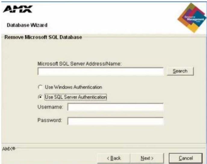
FIG. 48 Remove Microsoft SQL Database
-
Select the desired RMS application database to remove.
-
Click Next to continue.
The Database Wizard can only remove RMS application databases. If you attempt to remove another database, an error is returned and no action taken (FIG. 49).
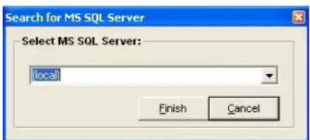
FIG. 49 Select Database to Remove
As a final confirmation to remove the database, you are prompted to enter the word destroy to confirm that you are certain about removing the database. Once a database has been removed, it cannot be recovered.
Enter destroy and click OK to continue.
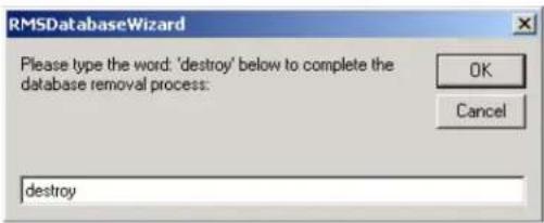
FIG. 50 Complete Database Removal Process
After the database has been removed, the Database Wizard performs a database connection test and then returns to the main menu.
Importing Data
The Database Wizard can import data files that were exported using this tool. This data file is an XML formatted collection of all the records in the database. This process is useful if you have created a new database and want to import data from an existing alternate database.
After selecting Import from the Import / Export menu, you are prompted to select the import file. After selecting the import file, click Next to begin the import process.
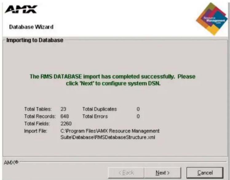
FIG. 51 Importing Database Complete
After the import file has been processed, the Database Wizard will return to the main menu.
Exporting Data
The Database Wizard can export all records in a database to a data file. This data file is an XML formatted collection of all the records in the database. This process is useful if you want to migrate to another database platform and want to export all records from your existing database. It can also be used to store backups of the data in your database.
After selecting Export from the Import / Export menu, you are prompted to select the export file. After selecting the export file, click Next to begin the export process.
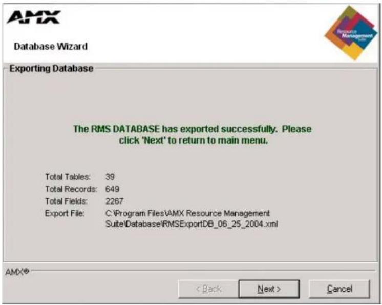
FIG. 52 Exporting Database Complete
After the export file has been completed, the Database Wizard returns to the main menu.
Converting A Database
The Database Wizard can fully automate the steps required to migrate from an existing database to an alternate database platform. The Database Wizard can migrate between any of the following database platforms.
• Microsoft SQL Server 2005
The steps required to migrate are as follows:
Read the corresponding sections for more information about each specific step.
- Export all data from existing RMS database.
- Create new RMS database.
- Import RMS data into new database.
- Configure RMS access to new database.
Click Next to continue.
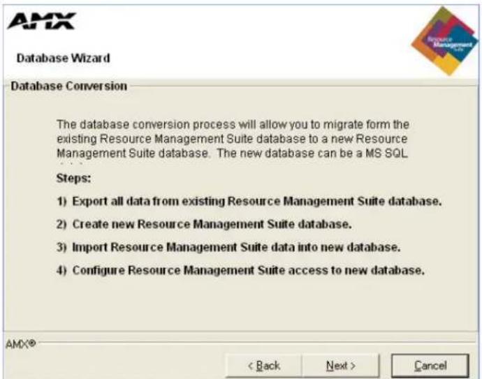
FIG. 53 Database Conversion
After the migration process has completed, the Database Wizard performs a database connection test and then returns to the main menu.
Applying Update Scripts
The Database Wizard can perform database maintenance and updates of the configured RMS application database using Update Scripts. Database update scripts are created by AMX to provide a means of updating the existing database in place.
- Select the desired update script.
- Click Next to continue.
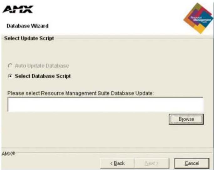
FIG. 54 Select Update Script
If the Configuration Wizard detects that the database must be upgraded, it automatically launches the Database Wizard Update Script dialog.
The Database Wizard tests to ensure that the update script can be applied to the existing configured database. It also ensures that the update script has not already been applied to the database. If these tests are passed, you are prompted with the Ready To Update message. If the update script does not pass these tests, an error message is displayed and you are not able to apply the update script.
Click Next to continue.
After the database script has been applied successfully, click Next to continue.
The Database Wizard performs a database connection test and then returns to the main menu.
Configuring Connection Settings
You can use the Database Wizard at anytime to configure the RMS application database connection settings. The RMS application uses a DSN-less connection, and thus stores all the database connection settings internally.
Database Server:
Enter the database server IP address or hostname.
Use Windows Authentication
Enable Windows Authentication or,
Use SQL Server Authentication
- Username:
Enter the database username (if needed). - Password:
Enter the database password (if needed).
Database Name:
Enter the database file name.
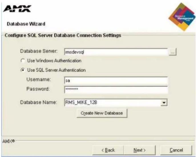
FIG. 55 Database Connection Settings
After configuring the RMS application database connection settings, the Database Wizard performs a database connection test and then returns to the main menu.
RMS Web User Interface
Overview
All navigation is done via the menu located on the left of the screen. Categories are in bold with their corresponding menu options indented beneath them.
Sign in Page
The Sign In page is the initial page of all RMS applications. Access and viewable areas are dictated by your user rights.
How do you sign in to RMS?
To sign in, enter a valid Username and Password, and click the Sign In button.
RMS Web User Interface
RMS Administration - The Administration Page is a menu listing of the following Administrator menu items (Refer to the RMS Administration section on page 53):
| RMS Web User Interface | |
| • RMS Dashboard: | The RMS Dashboard page is the initial page viewed when you log into the RMS application.Refer to the RMS Dashboard Page section on page 55. |
| • RMS Hotlist: | The RMS Hotlist page is the main view of the exception-based reporting system. All items provide a link to resolve that particular item.Refer to the RMS Hotlist section on page 57. |
| • System Status Page: | The System Status Page allows you to view the status of all rooms on a single screen.Refer to the System Status Page section on page 61. |
| • Management Page: | The Management Page allows you to configure and manage many aspects of RMS, organized into the following tabs:RoomsUsersPermissionsNotificationsSystemsDevicesInternal LogControl FunctionsRFID TagsRefer to the Management Page section on page 75. |
| • Reporting Page: | The options contained in the System Reports Page allow you to run a variety of different reports that help you diagnose and improve the user's experience with the system network. System reports are organized into the following categories:Room ReportsPower ReportsQuality of Service ReportsOrganizer ReportsRefer to the Reporting Page section on page 103. |
| RMS Web User Interface (Cont.) | |
| Configuration Page: | The options contained in theConfiguration Pageallow you to configure many aspects of the RMS system. Configuration options are organized into the following categories:Appointment Settings (Events)Internal LogNotification TemplatesPrestige LevelsLicensingHotlist SettingRefer to theConfiguration Pagesection on page 153. |
| Help Page: | TheHelp Pageis a list of links that can aid you in getting the best uses out of the RMS application.Refer to theHelp Pagesection on page 165. |
| Sitemap Page: | TheSitemap Pageis a hierarchical list of links to every page available within the RMS application; this page is restricted and populated according to the role of the user currently logged in to the RMS application.Refer to theSitemap Pagesection on page 169. |
| RMS Scheduling Page: | TheRMS Scheduling Pageprovides links to viewing the application schedule, creating an entry to the schedule, and access to the PDF version of the User’s Guide.Refer to theRMS Scheduling Pagesection on page 171. |
| RMS User Page: | TheRMS User Pagesare the portal for the RMS end-user. The options contained in the RMS User Page are organized into the following categories:Sign in PagePreferences PageUser Profile PageUser Notifications PageSign Out PageRefer to theRMS User Pagesection on page 179. |

Each of the RMS Web Interface Administrator menu items are described in the following sections.
RMS Administration
Administration Page
The Administration Page (FIG. 56) is a menu listing of the following Administrator menu items:
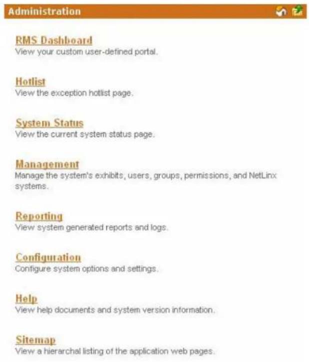
FIG. 56 RMS Administration Page
| Administration Page - Administrator menu items | |
| • RMS Dashboard View your custom user-defined portal. | |
| • Hotlist View the exception hotlist page. | |
| • System Status View the current system status page. | |
| • Management | Manage the system's rooms, users, groups, permissions, and NetLinx systems. |
| • Reporting | View system generated reports and logs. |
| • Configuration Configure system options and settings. | |
| • Control Functions Create and Manage Control Function Macros. | |
| • Help View help documents and system version information. | |
| • Sitemap | View a hierarchical listing of the application's web pages. |
RMS Administration
RMS Dashboard Page
Overview
The RMS Dashboard page is the initial page viewed when you log into the RMS application (FIG. 57).
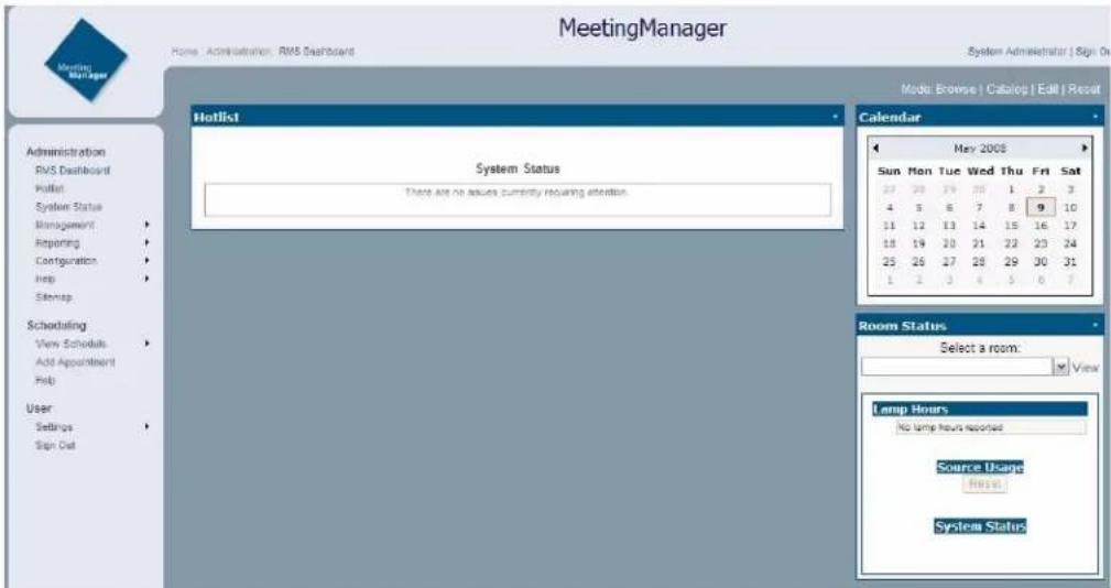
FIG. 57 RMS Dashboard
In addition to the navigation menu, the Dashboard is comprised of two columns, arranged and populated by user defined information.
By default the RMS Dashboard contains the Hotlist (RMS Hotlist section on page 57), Calendar and Room Status.
How Do You Change Modes?
The mode selection links are located at the top right of the RMS Dashboard. Change modes by clicking one of the following:
- Browse - The default mode for the RMS Dashboard.
- Catalog - Add items to the RMS Dashboard.
- Edit - Move RMS Dashboard items around the page.
Adding Contents
To add a content item to the RMS Dashboard:
- Click the RMS Dashboard link in the menu on the left of the RMS application.
- Click Catalog in the modes on the top right of the page.
- Select one of the links, Add Contents, Restore Contents or Imported Web Part Catalog.
Add Contents
The Add Contents section is a list of predefined Web Part definition files.
- Place a check in the box next to the items you want to add to the Dashboard.
Select the column within which you want the content displayed. - Click Add.
- Click Close.
Restore Contents
The Restore Contents section is a collection of Web Part definition files that have been previously removed from the Dashboard.
- Place a check in the box next to the items you want to restore to the Dashboard.
- Select the column within which you want the content displayed.
- Click Add.
- Click Close.
Imported Web Part Catalog
A Web Part catalog is a library of Web Part definition (.dwp) files that you can import into the RMS Dashboard.

See http://www.microsoft.com/technet/prodtechnol/sppt/sharepoint/reskit/part5/c22spprk.mspx for more information.
- Type a file name (.dwp) or click Browse to locate a Web Part file.
- Click Upload.
- Select the column within which you want the content displayed.
- Click Add.
- Click Close.
Moving Columns
Contents contained in either the Center or Right column can be moved up, down and to the other column on the Dashboard page.
To move a content item in the RMS Dashboard (Microsoft IE):
- Click the RMS Dashboard link in the menu on the left of the RMS application.
- Click either Catalog or Edit in the modes on the top right of the page.
- Click, hold and drag the top of the content item to be moved.
- Drag to a new location; the insertion point is indicated by a blue horizontal cursor.
- Click Browse in the modes on the top right of the page when you are done.
To move a content item in the RMS Dashboard (FireFox):
- Click the RMS Dashboard link in the menu on the left of the RMS application.
- Click either Catalog or Edit in the modes on the top right of the page.
- Click the view's menu item Edit.
- In Editor Zone, choose Zone and Zone Index to reposition the views.
- Click Browse in the modes on the top right of the page when you are done.
Resetting the RMS Dashboard
To return the RMS Dashboard to the default contents and settings:
- Click the RMS Dashboard link in the menu on the left of the RMS application.
- Click Reset in the modes on the top right of the page.
RMS Hotlist
Overview
The Hot List is the main view of the exception-based reporting system. All items provide a link to resolve that particular item.
Unassigned NetLinx Systems
The Hot List displays any new NetLinx systems that have connected to the RMS application (FIG. 58).
| Hotlist |
Unassigned NetLinx Systems
| Detection Time | Serial Humber | IP Address | Host Name | System Humber | Module Name | |
| 8/31/2006 7:29:17 PM | 192.168.213.69 | NetLinx_Exam02 | 2002 | MeetingManager (33001) | Add Exhibit | |
| 8/31/2006 7:29:17 PM | 192.168.213.69 | NetLinx_Exam02 | 2002 | MeetingManager (33002) | Add Exhibit | |
| 8/31/2006 7:29:17 PM | 192.168.213.69 | NetLinx_Exam02 | 2002 | MeetingManager (33004) | Add Exhibit | |
| 8/31/2006 7:29:17 PM | 192.168.213.69 | NetLinx_Exam02 | 2002 | MeetingManager (33005) | Add Exhibit | |
| 8/31/2006 7:29:17 PM | 192.168.213.69 | NetLinx_Exam02 | 2002 | MeetingManager (33006) | Add Exhibit | |
| 8/31/2006 7:29:17 PM | 192.168.213.69 | NetLinx_Exam02 | 2002 | MeetingManager (33003) | Add Exhibit | |
| 8/31/2006 7:09:06 PM | 192.168.213.67 | NetLinxExam03 | 2003 | MeetingManager (33005) | Add Exhibit | |
| 8/31/2006 7:09:06 PM | 192.168.213.67 | NetLinxExam03 | 2003 | MeetingManager (33006) | Add Exhibit | |
| 8/31/2006 7:09:06 PM | 192.168.213.67 | NetLinxExam03 | 2003 | MeetingManager (33001) | Add Exhibit | |
| 8/31/2006 7:09:06 PM | 192.168.213.67 | NetLinxExam03 | 2003 | MeetingManager (33002) | Add Exhibit | |
| 8/31/2006 7:09:06 PM | 192.168.213.67 | NetLinxExam03 | 2003 | MeetingManager (33003) | Add Exhibit |
FIG. 58 Hot List - Unassigned NetLinx Systems
When a new NetLinx system connects to the RMS application, it displays the following information and options:
| New NetLinx Systems | |
| • Detection Time The date, hour, minute and second the RMS server discovered the NetLinx system. | |
| • Serial Number Serial Number associated with the room. | |
| • IP Address IP Address associated with the room. | |
| • Host Name Host Name associated with the room. | |
| • System Number This is the system number of the NetLinx master. The system number is used in master-to-master configuration. | |
| • Module Name Module Name associated with the room. | |
| • Add Room | The Add Room link opens the Create New Room Page section on page 77. |
See Also:
- Create New Room Page section on page 77 - allows you to add rooms to RMS applications, monitor and schedule. Some information is provided by the NetLinx master when discovered by the RMS application
- Creating a New Room section on page 81 - upon initial discovery of a NetLinx master you have the option of adding that room to your list of monitored resources.
Parameter Needing Attention
Any issues that need attention in the RMS application are displayed on the Hot List (FIG. 59).
Parameter Needing Attention
| Status | Last Update | Exhibit | Device | Parameter | Current Value | Options |
| ✕ | 19/2/2007 2:34:23 PM | Conference Room 1 | System | Maintenance Request | need attention | |
| ✕ | 19/2/2007 2:33:06 PM | Conference Room 1 | System | Help Request | help me | |
| ✕ | 19/2/2007 2:34:40 PM | Conference Room 2 | System | Maintenance Request | RMS Simulation Client generated a maintenance request @ [10/02/07,13:34:32] | |
| ✕ | 19/2/2007 2:34:39 PM | Conference Room 2 | System | Help Request | RMS Simulation Client generated a help request @ [10/02/07,13:34:32] |
FIG. 59 Hot List - Parameter Needing Attention Section
If no issues need attention, no items are displayed in the Hot List. The HotList checks the RMS server for updates behind the scenes and the page is only refreshed if new HotList content is available.
When an item needs attention, such as a help request, the item will be displayed with the following information and options:
Status: Indicates the status of each issue:
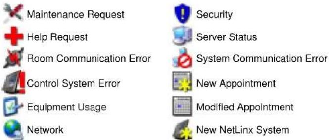
Last Update: Date and time of last system update
Room: Name of room where problem has occurred
Device: The name of the device with which the problem is associated
Parameter: The name of the parameter that requires attention
Current Value: Value of the parameter that requires attention
Reset: Reset the parameter to the default value.
View: View room's device list (in the View Devices Page)
Web Control: View the G4 Web Control web site.
Map: View the map of the room.
Response: Send response back to the room for the Help Request.
FIG. 60 Hot List - Parameter Needing Attention Section options
Viewing a Room When Appearing In Parameter Needing Attention List
The RMS application maintains a device list for each room and the status of each device listed in that room.
-
In the Hot List page, select View next to parameter needing attention. This launches the room's device view page.
-
Click Expand All to display all system status settings. Properly behaving parameters are indicated with a green check mark and any offending parameters are indicated with a red X.
-
Select View for the device parameter needing attention to view the Parameter Settings.
Resetting a Room When Appearing In Parameter Needing Attention List
If a notification has been set for a device it is necessary to reset it in the Hot List.
- Select the Hot List from the menu on the left side of the RMS application page.
- Select Reset for the offending parameter.
Responding To a Room When Appearing In Parameter Needing Attention
- Select the Hot List from the menu on the left side of the RMS application page.
- Select Respond to launch the Send Response page.
- Select either a pre-defined response from the drop down menu or type a response in the text field provided.
- Click Send.
Room Troller Failure
Troller failure occurs when the internal scheduling system has failed to attach to the scheduling system mailbox/account and synchronize appointments for the listed room (FIG. 61).
Exhibit Troller Failure
| Failure Time | Error Description | |
| 12/31/1979 6:00:00 PM | An error occurred while trolling events for: Steve700-1This room has not been configured for the scheduling interface. | Resolve |
| 12/31/1979 6:00:00 PM | An error occurred while trolling events for: Steve700-2Room is not configured for a scheduling plugin. | Resolve |
| 12/31/1979 6:00:00 PM | An error occurred while trolling events for: Steve700-3 (33003)Room is not configured for a scheduling plugin. | Resolve |
| 12/31/1979 6:00:00 PM | An error occurred while trolling events for: Steve700-4 (33004)Room is not configured for a scheduling plugin. | Resolve |
| 12/31/1979 6:00:00 PM | An error occurred while trolling events for: Steve700-6 (33005)Room is not configured for a scheduling plugin. | Resolve |
| 12/31/1979 6:00:00 PM | An error occurred while trolling events for: Steve700-6 (33006)Room is not configured for a scheduling plugin. | Resolve |
| 12/31/1979 6:00:00 PM | An error occurred while trolling events for: 2004-1This room has not been configured for the scheduling interface. | Resolve |
| 12/31/1979 6:00:00 PM | An error occurred while trolling events for: Bens SampleRoom is not configured for a scheduling plugin. | Resolve |
| 12/31/1979 6:00:00 PM | An error occurred while trolling events for: 2003-1Room is not configured for a scheduling plugin. | Resolve |
| 12/31/1979 6:00:00 PM | An error occurred while trolling events for: 2003-2Room is not configured for a scheduling plugin. | Resolve |
| 12/31/1979 6:00:00 PM | An error occurred while trolling events for: 2003-3Room is not configured for a scheduling plugin. | Resolve |
FIG. 61 Hot List - Room Troller Failure Section
| Room Troller Failure | |
| • Failure Time The time | stamp from the server when the Troller Failure was detected. |
| • Error Description What | error occurred and in which room. |
| • Resolve | Link to the View Room Settings Page section on page 79.Check the scheduling plug-in mailbox configuration for this room. |
RMS Hotlist
System Status Page
Overview
The System Status Page allows you to view the status of all rooms on a single screen (FIG. 62).

FIG. 62 System Status Page
Each room entry lists the Room Name, Room Power Status, Help Request, Room Communication Error, System Error, Maintenance Issues, Network Errors, and Security Errors.
| System Status | |
| • Room Name The room name for this row. | A link to the View Room Settings page for a room. This link provides access to a detailed list of all devices and device parameters for a given room. To investigate more thoroughly, click on this link. |
| • Power The Room Power status for this room. | |
| • Help Request The Help Request status for this room. | |
| • Comm Error The Room Communication Status for this room. | |
| • System Error The Control System status for this room and its devices. | |
| • Maintenance The Maintenance Request status for this room and its devices. | |
| • Network The Network status for this room and its devices. | |
| • Security The Security status for this room and its devices. | |
Rooms are displayed in a tree view of groups and rooms. By default, all groups are rolled up unless an error has occurred. In that case, the group containing errors is unrolled. Show Triggered redraws using the default view. Expand all unrolls all groups. Collapse all rolls up all groups. Refresh refreshes this page.
The Room Power Status field will display a green power icon when the room power is on. Under normal operating conditions, this page will display the power status for all rooms with a green check in all error columns. If an error does occur the System Status page will display a red X for the room with the error. Additionally, the error will appear as an item in the Hot List.
Auto-Refresh
The System Status Page and the View Devices Page (FIG. 63 on page 62) auto refresh every 30 seconds by default.
- You can turn on/off the auto refresh by Setting ForcePageRefresh to true/false in web.config file.
- You can also set how often you want the page refresh by changing PageRefresh in web.config file.
Viewing System Status Information
To access the System Status page:
- Select System Status in the menu on the left side of the RMS application.
- Any rooms containing a parameter needing attention are expanded for viewing.
Viewing Device Information on the System Status Page
- Select System Status in the menu on the left side of the RMS application.
- Expand the group name containing the status you want to check.
- Select the room name to view the device information page.
View Devices Page
The View Devices page lists the devices and the status of their various parameters as the RMS application monitors them (FIG. 63).
| Device Name | Manufacturer | Model | Device Humber | Syslog | Internal Log | Windows Log | Options |
| Display | Display Manufacturer | Display Model | 5001:1:0 | ☐ | ✓ | ☐ | View |
| Name | Current Value | Status | Status Type | Options | |||
| Device Online | Online | ✓ | Control System Error | View | |||
| RFID Battery Level | 0 % | ✓ | Maintenance | View | |||
| RFID Detected Location | Steve 700 | ✓ | Not Assigned | View | |||
| RFID Signal Strength | 0 | ✓ | Not Assigned | View | |||
| RFID Tag Online | Offline | ✘ | Security | View | |||
| Device Name | Manufacturer | Model | Device Humber | Syslog | Internal Log | Windows Log | Options |
| Main Touch Panel | AMX Corp. | CV15 Video Touch Panel | 10001:1:0 | ☐ | ✓ | View | |
| Device Name | Manufacturer | Model | Device Humber | Syslog | Internal Log | Windows Log | Options |
| Rack Power | AMX | NI-3000 Relay | 5001:8:0 | ☐ | ✓ | View | |
| Device Name | Manufacturer | Model | Device Humber | Syslog | Internal Log | Windows Log | Options |
| RFID Reader 1 | AMX Corp. | Unknown | 96:1:0 | ☐ | ✓ | View | |
| Device Name | Manufacturer | Model | Device Humber | Syslog | Internal Log | Windows Log | Options |
| RFID Reader 3 | AMX Corp. | Unknown | 98:1:0 | ☐ | ✓ | View | |
| Device Name | Manufacturer | Model | Device Humber | Syslog | Internal Log | Windows Log | Options |
| RFID Reader 4 | AMX Corp. | Anterus RFID Reader | 99:1:0 | ☐ | ✓ | View | |
| Device Name | Manufacturer | Model | Device Humber | Syslog | Internal Log | Windows Log | Options |
| Source Usage | AMX Corp. | RMS | 0:0:0 | ☐ | ✓ | View | |
| Device Name | Manufacturer | Model | Device Humber | Syslog | Internal Log | Windows Log | Options |
FIG. 63 View Devices Page
The screen is divided into sections for each device, with each section containing the following information:
| Device List Information | |
| • Device Name The name of the monitored device. | |
| • Manufacturer The manufacturer of the monitored device. | |
| • Model The model of the monitored device. | |
| • Device Number | The NetLinx device number for this device as defined in the NetLinx program. |
| • Syslog, Internal Log, Windows Log | Checkboxes indicate if the device will report any errors to the various logs. |
| • View | This link provides more details for the device settings and allows them to be modified. See the Device Information Page for more information. |
Each device can have one or more monitored parameters. They are collapsed within the table directly below the device and contain the following information:
| Device List Monitored Parameters | |
| • Name The name of the parameter being monitored. | |
| • Current Value The current value for the parameter. | |
| • Status This checkbox indicated if the parameter is operating within or outside of its threshold value. The tool tip for this checkbox provides details about the threshold for the parameter. | |
| • Status Type This is the status type with which the parameter is associated. | |
| • View This link provides more details for the parameter settings and allows them to be modified. See Device Parameter Page section on page 68 |
Create Device Page
The Create Device page allows you to enter device information for a monitored device (FIG. 64).
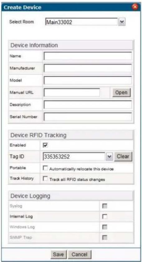
FIG. 64 Create Device Page
Access this page by clicking Create Device on the View Devices page.
| Create Device | |
| • Name The name of the monitored device. | |
| • Manufacturer The manufacturer of the monitored device. | |
| • Model The model of the monitored device. | |
| • Manual URL A URL link to the manual on the manufacturer's web site. | |
| • Description A description of the monitored device. | |
| • Serial Number The serial number of the monitored device. | |
| • Enabled Allows you to enable or disable RFID tracking for the device. | |
| • Tag ID Allows you to enter the RFID tag ID for the device. | |
| • Portable | Allows you to enable or disable the RFID automatic location tracking for the device. |
| • Track History Allows you to enable or disable the RFID tracking history for the device. | |
| • Syslog Allows you to turn on the system log for the device. | |
| • Internal Log Allows you to turn on the internal log for the device. | |
| • Windows Log | Allows you to turn on the Windows log for the device. |
| • SNMP Trap | Allows you to turn on the SNMP trap log for the device. |
Execute Control Function Page
The Execute Control Function page allows you to execute control functions at the device level within specified rooms (FIG. 65).
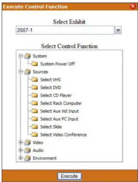
FIG. 65 Execute Control Function Page

RMS uses i!-ConnectLinx to facilitate these controls.
i!-ConnectLinx provides the mechanism to expose actions to the RMS server and to manage action execution on the NetLinx system.
Once a user builds a preset from the actions in the i!-ConnectLinx action list, the RMS server makes a request to i!-ConnectLinx to execute those actions.
i!-ConnectLinx handles this request and presents it to the NetLinx program for execution. See the i!-ConnectLinx section of the RMS Programmer's guide for details on programming.
| Execute Control Function | |
| Select Room A drop-down | combo box of available rooms and groups within the RMS system. |
| Select Control Function | Detected control functions for the selected room. |
| Execute Executes the selected control function. | |
Device Information Page
The Device Information page lists the device settings and allows you to modify them (FIG. 66).
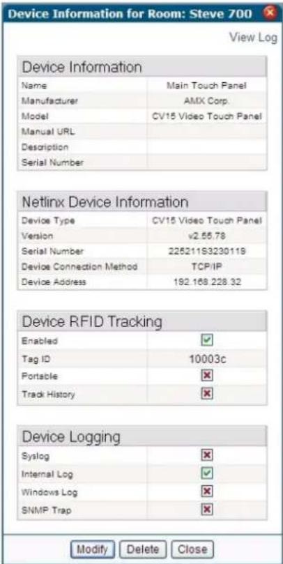
FIG. 66 Device Information Page
Not all sections displayed and defined here appear for all devices.
| Device Information | |
| • Name The name of the monitored device. | |
| • Manufacturer The manufacturer of the monitored device. | |
| • Model The model of the monitored device. | |
| • Manual URL A URL link to the manual on the manufacturer's web site. | |
| • Description A description of the monitored device. | |
| • Serial Number The serial number of the monitored device. | |
| • Modify | Click to modify the device. See the Viewing a Device Log section on page 74. |
| Device Information (Cont.) | |
| • Move | Click to move the device to a different room. This button is only visible if one of the following conditions is true:• The device is an unmanaged device and RFID Tag Tracking is disabled.• The device is an unmanaged device and RFID Tag Tracking is enabled and is not currently detected by any RFID reader in the system.• The device is an unmanaged device and RFID Tag Tracking is enabled and the RFID device portable option is disabled. |
| • Delete Click to delete the device. The system device cannot be deleted. | |
| • Back (X) Return to the device list. | |
The NetLinx Device Information section contains information for the NetLinx device with which this device is associated. For instance, if a projector is connected to NetLinx through an NXC-COM2 card, this table will contain information about the NXC-COM2 card.
| NetLinx Device Information | |
| • Device Type The type of NetLinx device. | |
| • Version The firmware version of the NetLinx device. Note: This is not available for AxLink devices. | |
| • Serial Number The serial number of the NetLinx device. Note: This is not available for AxLink devices. | |
| • Device Connection Method | The connection type of this device (ICSNet, TCP/IP, or AxLink). • This can be useful in diagnosing device connection problems. |
| • Device Address The physical address of the device. • For ICSNet, this is the hardware address of the device on the ICSNet bus. • For TCP/IP connections, this is the IP address of the device. • For AxLink, this is "AxLink." | |
The Device RFID Tracking section contains information about tracking devices with associated RFID tags. This section only appears if you enable the global option for RFID support in the RMS Configuration Wizard.
| Device RFID Tracking | |
| • Enabled | Allows you to enable RFID tracking for the target device. The default value is Disabled. |
| • Tag ID Allows | you to enter the RFID tag to associate with the target device. |
| • Portable | Allows you to enable the RFID automatic location tracking for the target device. The default value is Disabled. |
| • Track History | Allows you to enables RFID tracking history for the target device. This option is only available if you enable the global system RFID History Tracking option. The default value is Enabled. |
The checkboxes in the Device Logging section indicate if the device will report any errors to the various logs. Green checks are enabled and red Xs are disabled.
| Device Logging | |
| • Syslog Green checks = enabledRed Xs = disabled. | |
| • Internal Log | |
| • Windows Log | |
| • SNMP Trap | |
See Also:
● Internal Log Report Page section on page 148
- Viewing a Device Log section on page 74
Modify Device Information Page
To modify a device, click Modify. The Modify Device Information Page allows you to change values (FIG. 67).
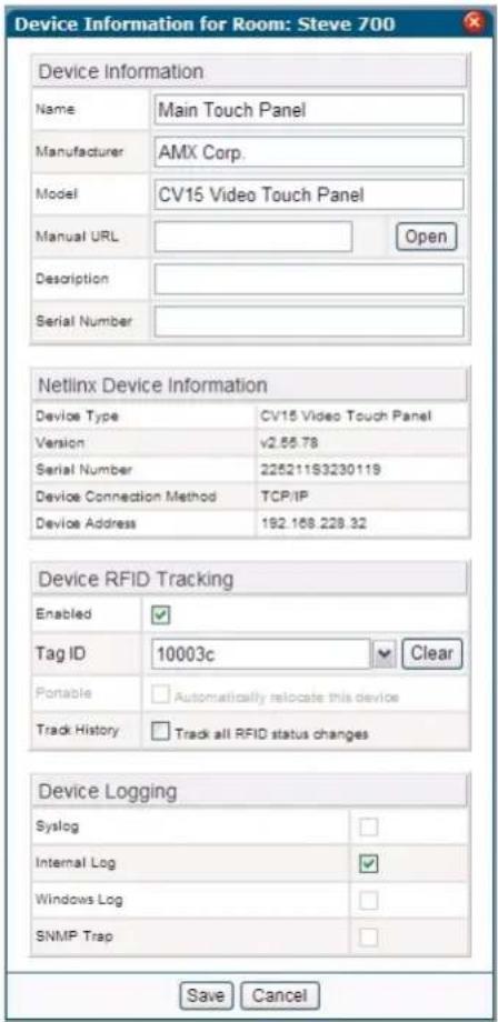
FIG. 67 Modify Device Information Page
While in this screen, you can make changes to the Device Information and Device Logging sections of the Device Information page.
See Also:
● Device Information Page section on page 65.
Device Parameter Page
Parameter information attributed to a device monitored by the RMS application is listed in the Device Parameter page (FIG. 68).
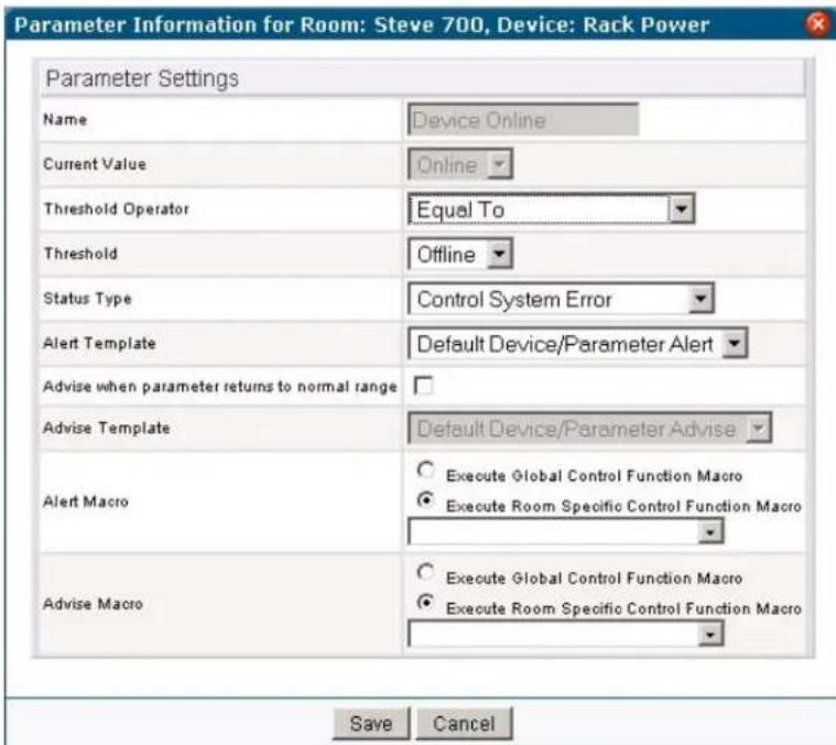
FIG. 68 Device Parameter Page
| Parameter Settings | ||
| • Name The name of the parameter being monitored. | ||
| • Current Value The value of the parameter | ||
| • Threshold Operator The threshold value is the value for which this parameter is considered to indicate a problem or fault. The comparison operator is used to detect when the value changes from the un-faulted to the faulted condition.The comparison operators "Less Than", "Less Than or Equal To", "Greater Than", "Greater Than or Equal To", "Equal To", and "Not Equal To" can be used for string and number parameters.The comparison operators "Contains" and "Does Not Contain" are primarily used for string parameters.Example: "Lamp Hours" might have a threshold value of 1000 and any value over this would require maintenance. The comparison operator would then be "Greater Than".When this parameter changes from a value that is not greater than 1000 to a value that is greater than 1000, the parameter will faulted.When the value changes from a value greater than 1000 to a value not greater than 1000, the fault status is cleared. | ||
| • Threshold The threshold value | ||
| Parameter Settings (Cont.) | ||
| • Status Type | The status represents the type of problem a faulted condition represents. Status Types include: | |
| • Control System Error• Equipment Usage• Help Request• Maintenance• Modified Appointment• N e t w o r k• New Appointment | • New NetLinx System• Not Assigned• Room Communication Error• S e c u r i t y• Server Status• System Communication Error | |
| Example: When "Lamp Hours" changes from an un-faulted (not greater than 1000) to a faulted (greater than 1000), this change represents a "Maintenance Request" status that requires an AV technician to repair the equipment.• If the "Device Online" parameter changes from "Online" to "Offline", this change could represent a "Security" or "Control System Error" status.• The RMS application will route the status type to the appropriate personnel as determined by the Notification Configuration settings. | ||
| • Alert Template The notification template to use when the parameter's value is outside the normal operating range. | ||
| • Advise when parameter returns to normal range | The RMS application sends a notification for a parameter when it returns to its normal operating range. | |
| • Advise Template The notification template to use when the parameter's value returns to the normal operating range. | ||
| • Alert Macro | • The Control Function macro that executes when a device parameter exceeds its configured threshold.• The Execute Global option allows you to select any defined macro in the system and when the parameter Alert occurs, the macro executes in every room that is part of the macro.• The Execute Room option allows you to select a macro defined for the room and when the Alert occurs, the macro executes in the room. | |
| • Advise Macro | • The Control Function macro that executes when a device parameter returns to its configured threshold.• The Execute Global option allows you to select any defined macro in the system and when the parameter Advise occurs, the macro executes in every room that is part of the macro.• The Execute Room option allows you to select a macro defined for the room and when the Advise occurs, the macro executes in the room. | |
● History - Launches the Device Parameter History Page section on page 70.
- Modify - Launches the Modify Parameter Page section on page 71.
- Delete - Deletes the parameter.
See Also:
Configure Notification Template Page section on page 156 - modify notification templates to fulfill your own needs.
Device Parameter History Page
The Device Parameter History page contains status tracking information for each device assigned to a room (FIG. 69).
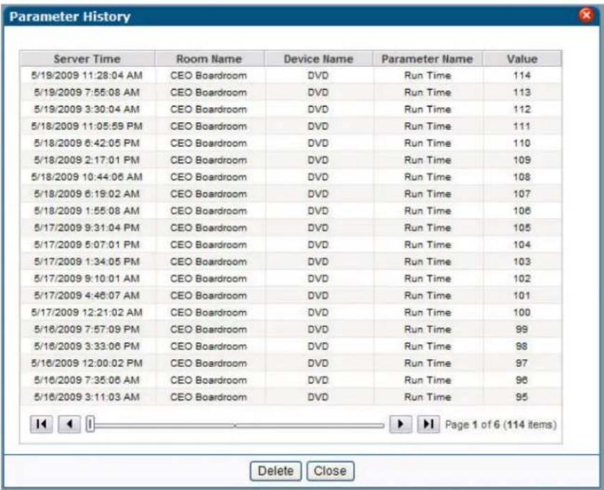
FIG. 69 Device Parameter History Page
| Device Parameter History | |
| • Server Time The date and time the status was logged as set by the server. | |
| • Room Name The name of the room to which the device is assigned. | |
| • Device Name The assigned name of the device. | |
| • Parameter Name The assigned name of the parameter tracked by the system status. | |
| • Value The tracked value as it relates to the assigned parameter. |
- Delete - Clears the Device Parameter History.
Modify Parameter Page
Make changes to existing device parameters via this page.
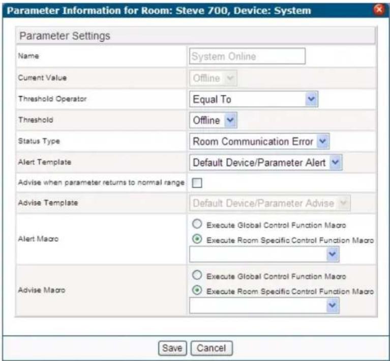
FIG. 70 Modify Parameter Page
| Parameter Settings | |
| • Name The friendly name of the parameter. You cannot change the value of this parameter. | |
| • Current Value The value of the parameter | |
| • Threshold Operator A drop down selection the threshold designator for the parameter | |
| • Threshold The threshold value. | |
| • Status Type A drop down selection for the category to which the parameter belongs. | |
| • Alert Template | The notification template to use when the parameter's value is outside the normal operating range.Drop down selection of the types of alert templates available. |
| • Advise when parameter returns to normal range | When checked, the RMS application sends a notification for a parameter when it returns to its normal operating range. |
| • Advise Template | The notification template to use when the parameter's value returns to the normal operating range.Drop down selection of the types of advise templates available. |
- Reset - Resets all settings for the parameter to default values.
- Save - Confirms the changes for the parameter changes and returns to the Device Parameter Page
- Cancel - Exits to the Device Parameter Page without saving changes.
Viewing Device parameters
- Select System Status from the menu on the left side of the RMS application.
- Expand the group name containing the status you want to check.
- Select the room name to view the device information page.
- Click View for the selected parameter in the Device List Monitored Parameters section. The Device Parameter page opens.
Viewing Device Parameter history
- Select System Status from the menu on the left side of the RMS application.
- Expand the group name containing the status you want to check.
- Select the room name to view the device information page.
- Click View for the selected parameter in the Device List Monitored Parameters section. The Device Parameter page opens.
- Click History to launch the The Device Parameter History page.
Deleting Device Parameter history
- Select System Status from the menu on the left side of the RMS application.
- Expand the group name containing the status you want to check.
- Select the room name to view the device information page.
- Click View for the selected parameter in the Device List Monitored Parameters section. The Device Parameter page opens.
- Click History to open the Device Parameter History page.
- Click Delete.
Modifying Device Parameters
- Select System Status from the menu on the left side of the RMS application.
- Expand the group name containing the status you want to check.
- Select the room name to view the device information page.
- Click View for the selected parameter in the Device List Monitored Parameters section. The Device Parameter page opens.
- Click Modify. The Modify Parameter page opens.
-
Edit any of the following:
-
Select the Threshold Operator from the drop-down combo box.
- Edit the threshold value in the field Threshold (in).
- Set the Status Type in the drop-down combo box.
- Set an Alert Template from the drop-down combo box.
-
Enable or disable the option Advise when parameter returns to normal range. If you enable this option, set the Advise Template from the drop-down combo box.
-
Click Reset to reset the parameter.
-
Click Save to save.
Deleting Device Parameters
- Select System Status from the menu on the left side of the RMS application.
- Expand the group name containing the status you want to check.
- Select the room name to view the device information page.
- Click View for the selected parameter in the Device List Monitored Parameters section. The Device Parameter page opens.
- Click Delete.
Viewing Detailed Device Information
- Select System Status from the menu on the left side of the RMS application.
- Expand the group name containing the status you want to check.
- Select the room name to view the device information page.
- Click View for the selected parameter in the Device List Information section. The Device Information page opens.
Modifying Device Information
- Select System Status from the menu on the left side of the RMS application.
- Expand the group name containing the status you want to check.
- Select the room name to view the device information page.
- Click View for the selected parameter in the Device List Information section. The Device Information page opens.
-
Click Modify. The Modify Device Information page opens.
-
Edit any of the following:
-
The device Name
● The device Manufacturer
• The device Model
● The Manual URL for the device
● The Description of the monitored device
● The serial number of the monitored device. -
Place a check next to the Device Logging tools you want enabled.
-
Click Save to save.
Moving a Device to a New Room
- Select System Status from the menu on the left side of the RMS application.
- Expand the group name containing the status you want to check.
- Select the room name to view the device information page.
- Click View for the selected parameter in the Device List Information section. The Device Information page opens.
- Click Move. The Move Device page opens (FIG. 71):
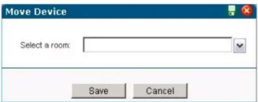
FIG. 71 Move Device page
-
Use the Select Room drop-down combo box to select a new room.
-
Click Save.

NOTE
The only devices that you can move are user created devices that do not have RFID tags attached to them.
Deleting Device Information
- Select System Status from the menu on the left side of the RMS application.
- Expand the group name containing the status you want to check.
- Select the room name to view the device information page.
- Click View for the selected parameter in the Device List Information section. The Device Information page opens.
- Click Delete.
Viewing a Device Log
- Select System Status from the menu on the left side of the RMS application.
- Expand the group name containing the status you want to check.
- Select the room name to view the device information page.
- Click View for the selected parameter in the Device List Information section. The Device Information page opens.
- Click View Log. The Internal Log Report page opens.
Executing a Device Control Function
- Select System Status from the menu on the left side of the RMS application.
- Expand the group name containing the status you want to check.
- Select the room name to view the device information page.
- Click Device Control. The Execute Control Function page opens. Only control functions available in this room are listed in this page. You can change rooms via the Select Room drop-down combo box.
- Navigate to the control function you wish to execute in this room by double-clicking on each function and device type.
- Click Execute.
Management Page
Overview
The screen images included in this document show the term "Exhibit" rather than "Room" for this tab and associated options.
The terms are interchangeable, as different versions RMS are specifically tailored to different types of installations (in this case, venues).
Management - Rooms Page
The Management - Rooms page is shown in FIG. 72:
![Management Rooms Users Permissions Notifications Systems Devices Internal Log Control Functions FFID Tape View and manage configured rooms. Create Group | Create Room | Send Message to Rooms Groups Rooms Room Name Licensing Serial Number IP Address Host Name System Number Online Options [Default Group] Type in ConFrames (In) Steve 700 210503p4440949 192.168 228.31 Steve_700 1 View | Devices | ? Rooms](/content/2026/06/1185428/images/9c0fc8c93f31ee4f2d010139c3b882f72fe811a7ada8a6c0c4b3b00ac1a43f55.jpg)
FIG. 72 Management - Rooms Page
Create New Group Page
Select Create Group in the Management - Rooms page to access the Create New Group page shown in FIG. 73:
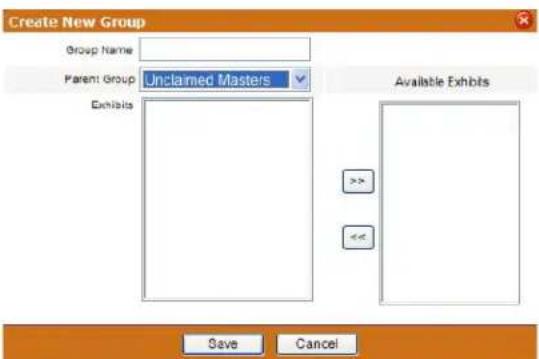
FIG. 73 Create New Group Page
| Create New Group Page Options | |
| • Group Name Text | field for friendly name of the group. |
| • Parent Group Drop | down list establishes the groups relation to other groups. A group can be separate, a child of another group, or the parent of other groups. |
| • Room Rooms included in the group. | |
| • Available Rooms | Rooms that can be included in the group. |
| • << / >> Moves a set | selected room to the left and right adding or removing the room from the group list. |
Example Group structures:
- City
- Building
- Floor
- Campus
• Building
- Floor
- Country
• City
- Department
Creating a New Group
- From the Management - Rooms page, select Create New Group.
- In the Create New Group Page (FIG. 73 on page 75), type the name of the group in the field Group Name.
- If it is a group of groups, select the Parent Group in the drop down list.
- If it is a group of rooms, select the rooms in the window Available Rooms and click the << button to move the rooms to the Rooms window.
- Click Save to save, Cancel to cancel.
To reassign a room to another group, delete it from the group to which it currently belongs, then add the room to the desired group.
Viewing Group Settings
- Groups are displayed in the Groups window of the Management - Rooms page.
- Select a group, and click View. The View Group Setting page opens.
View Group Setting Page
| View Group Setting Page Options | |
| • Group Name Text field for friendly name of the group. | |
| • Parent Group Drop down list establishes the groups relation to other groups. A group can be separate, a child of another group, or the parent of other groups. | |
| • Room Rooms included in the group. | |
| • Modify Launches the Modify Group Setting Page section on page 77. | |
| • Delete Deletes the selected group. |
Editing a Group
- Select a group, and click View.
- Click Modify to access the modify options in the Modify Group Setting page.
- Edit any of the following fields:
- Group Name
- Set or remove the Parent Group from the drop down list
-
Add (<<) or Remove (>>) rooms within the group
-
Click Save to save, Cancel to cancel.
Modify Group Setting Page
| Modify Group Setting Page Options | |
| • Group Name Text | field for friendly name of the group. |
| • Parent Group Drop | down list establishes the groups relation to other groups. A group can be separate, a child of another group, or the parent of other groups. |
| • Room Rooms included in the group. | |
| • Available Rooms | Rooms that can be included in the group. |
| • << / >> Moves a selected room to the left and right adding or removing the room from the group list. | |
Deleting Groups
- Select a group, and click View Group. The View Group Setting page opens.
- Click Delete.
Create New Room Page
Select Create Room in the Management - Rooms page to access the Create New Room page (FIG. 74):
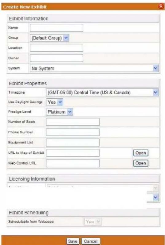
FIG. 74 Create New Room ("Exhibit") Page
The Create New Room page allows you to add rooms to RMS applications, monitor and schedule. Some information is provided by the NetLinx master when discovered by the RMS application.
| Create New Room Page Options | |
| Room Information | |
| • Name The name of the | room. |
| • Location The location of the room | |
| • Owner Room's owner | |
| • Master A drop down list to select the NetLinx master with which the room is associated. | |
| Room Properties | |
| • Time zone and Use Daylight Savings | This is the time zone setting for the room. Select the appropriate time zone from the drop down list. |
| • Use Daylight Savings | This is the daylight saving setting for the room. Select Yes to enable the use of Day-light Savings from the drop down list. |
| • Prestige Level | Select the level from the drop down list. This is the prestige level for the room. This value is optional but helps users find a room that meets their needs through the RMS application's room search. |
| • Number of Seats | This is the number of seats for the room. This value is optional but helps users find a room that meets their needs through the RMS application's room search. |
| • Phone Number In the event the room is equipped with a phone, this is the number for that phone. | |
| • Equipment List | This is the equipment list for the room. This value is optional but helps users find a room that meets their needs through the RMS application's room search. All equipment items should be separated by a comma. |
| • URL to Map of Room | This is a URL link to a map of the room. While the RMS application does not provide any facility to generate and manage maps of your facility, this link is provided so users can access a map of the facility with the room shown if you have access to such maps. Click Open to browse to the selected file. |
| • Web Control Path | This is the il-WebControl URL of the room. This link is provided to allow quick access to any HTML based control panels that may have been programmed into the NetLinx system. Click Open to browse to the selected file. |
| Licensing Information | |
| • Asset License | An Asset License allows you to monitor the room and assign notifications, but does not allow for scheduling. A room such as an equipment closet, where you may want to monitor equipment, would be an example of a room that is not schedulable. If an Asset License is available you can select one from the drop down list. If you cannot select a license, you must contact AMX to purchase a license for this system. |
| • Scheduling License | A Scheduling License allows you to schedule and reserve the room and execute macros. If a Scheduling License is available you can select one from the drop down list. If you cannot select a license, you must contact AMX to purchase a license for this system. |
View Room Settings Page
Viewing Room Settings
- Rooms are displayed in the Rooms window of the Management - Rooms page.
- Select a room, and click View. The View Room Setting page (FIG. 75) opens.
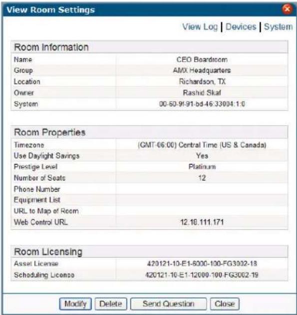
FIG. 75 View Room ("Exhibit") Settings Page
| View Room Settings Page | |
| Room Information | |
| • Name The name of the room. | |
| • Location The location of the room | |
| • Owner Room's owner | |
| • Master The NetLinx master with which the room is associated. | |
| Room Properties | |
| • Time zone and Use Daylight Savings | This is the time zone setting for the room. |
| • Use Daylight Savings | This is the daylight saving setting for the room. |
| • Prestige Level This is the prestige level for the room.This value is optional but helps users find a room that meets their needs through the RMS application's room search. | |
| • Number of Seats This is the number of seats for the room.This value is optional but helps users find a room that meets their needs through the RMS application's room search. | |
| • Phone Number In the event the room is equipped with a phone, this is the number for that phone. | |
| • Equipment List This is the equipment list for the room.This value is optional but helps users find a room that meets their needs through the RMS application's room search. | |
| View Room Settings Page (Cont.) | |
| • URL to Map of Room | This is a URL link to a map of the room. |
| • Web Control Path | This is the i!-WebControl URL of the room.This link is provided to allow quick access to any HTML based control panels that may have been programmed into the NetLinx system. |
| Licensing Information | |
| • Asset License This is the Asset License number for the room.If you do not have a license, you must contact AMX to purchase a license for this system. | |
| • Scheduling License | This is the Scheduling License number for the room.If you do not have a license, you must contact AMX to purchase a license for this system. |
See Also...
● Internal Log Report Page section on page 148
• View Devices Page section on page 62
• View System Page section on page 92
- Send Question Page section on page 80
Send Question Page
Use the RMS application interface to communicate simple questions to selected rooms, via the Send Question page (FIG. 76).
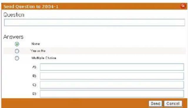
FIG. 76 Send Question Page
| Send Question Page options | |
| • Question Text field for you to type a question; the question is sent to the room. | |
| • A n s w e r sNone | No possible answer to your question is provided to the recipient. |
| Yes or No | The option of yes or no is provided to the recipient. |
| MultipleChoice | Using the text fields, A, B, C, and D, provide the recipient 4 possible answers. |
Creating a New Room
- In the Management - Rooms page, select Create Room.
- In the Create New Room Page, type the Room Information;
● The fields are Name, Location, Owner.
- If there is a NetLinx master, select it from the drop-down combo box.
- Enter the Room Properties;
● The text fields are Number of Seats, Phone Number, and Equipment List.
- The drop-down combo box selections are Timezone, Use Daylight Savings, and Prestige Level. URL to Map of Room and Web Control URL are either text field or click Open to browse to the desired files.
● While this information is not required it does aid your users in deciding rooms for scheduling use.
- In the Licensing Information section, select the license type to use for the room.

The Asset License and Scheduling License drop-down combo boxes are only enabled if available licenses are detected on the RMS server.
- Click Save to save, Cancel to cancel.
Editing a Room
- In the Management - Rooms page, select View.
-
In the View Room Settings Page, click Modify.
-
Edit the Room Information;
● The fields are Name, Location, Owner.
- If there is a NetLinx master, select it from the drop-down combo box.
- Edit the Room Properties;
● The text fields are Number of Seats, Phone Number, and Equipment List.
- The drop-down combo box selections are Timezone, Use Daylight Savings, and Prestige Level. URL to Map of Room and Web Control URL are either text field or click Open to browse to the desired files.
- While this information is not required it does aid your users in deciding rooms for scheduling use.
- In the Licensing Information section, select the license type to use for the room.

The Asset License and Scheduling License drop-down combo boxes are only enabled if available licenses are detected on the RMS server.
- Click Save to save, Cancel to cancel.
Viewing Room settings
In the Management - Rooms page, select View.
Deleting Rooms
- In the Management - Rooms page, select View.
- In the View Room Settings Page, click Delete.
Sending a Question to a Room
- In the Management - Rooms page, select View.
- In the View Room Settings Page, click Send a Question. The Send Question page opens.
- Type your Question in the field provided.
- Select your Answer type. If you selected Multiple Choice, type the possible answers in the fields provided.
- Click Send.
Management - Users Page
The Management - Users page is shown in FIG. 77:
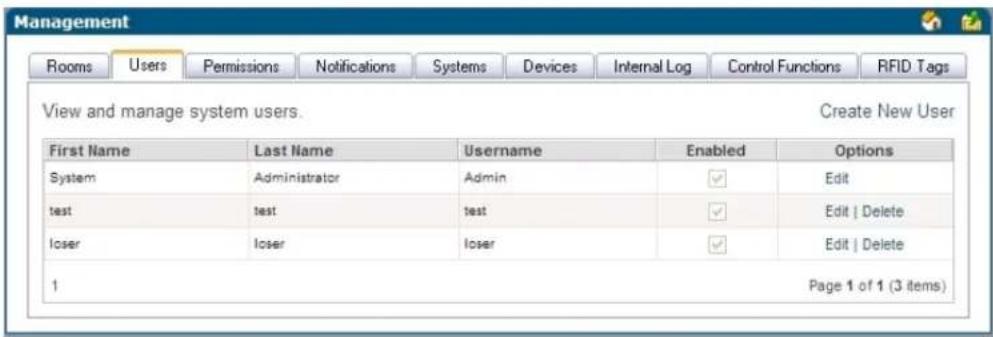
FIG. 77 Management - Users Page
| System Users Information | |
| • First Name | The user's first name. |
| • Last Name | The user's last name. |
| • Username | The username of the user; the username is used at the time of log in. |
| • Enabled When checked, the user account is enabled and can be used. | |
| • Options | • Edit - Launches the Edit User Page.• Delete - Deletes the selected user from the system.Note: You cannot delete the System Administrator. |
Create New User Account Page
A user must be in place in order for the RMS application to send notifications. In addition, users are used to control access to the system. Once a user has been created, notifications can be assigned.
New Users are created via options in the Create New User Account page (FIG. 78):
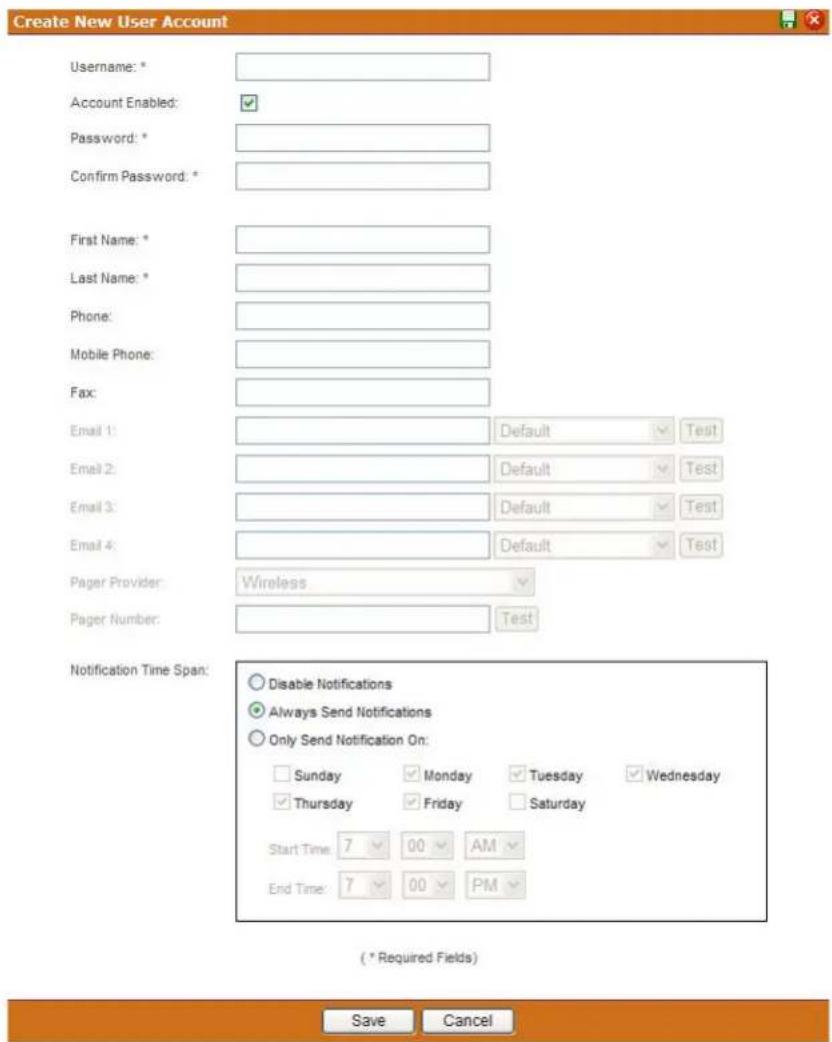
FIG. 78 Create New User Account Page
| Create New User Account Page | |
| •Username Username for login. This field is required. | |
| •Account Enabled | When unchecked, this account cannot log into the RMS application. However, this user can still receive notifications. |
| •Password Password for login. This field is required. | |
| •Confirm Password Confirm password for login. This field is required. | |
| •First Name The first name of the user. This field is required. | |
| •Last Name The last name or surname of the user. This field is required. | |
| •Phone | The phone number of the user. This value is not used by the RMS application; it is only used for reference by the RMS application administrators. |
| Create New User Account Page (Cont.) | |
| • Mobile Phone | The mobile phone number of the user. This value is not used by the RMS application; it is only used for reference by the RMS application administrators. |
| • Fax The FAX number of the user. This value is not used by the RMS application; it is only used for reference by the RMS application administrators. | |
| • Email 1 | The primary email account for this user if no other account is specified. This address will be used for notification emails. Set it as the default from the drop-down combo box to the right of the field. Send a test notification to the account by pushing Test. You can enter up to 100 characters for an email address. |
| • Email 2, Email 3, Email 4 | These are the secondary email accounts for this user. These addresses will be used for notification emails. Set it as the default from the drop-down combo box to the right of the field. Send a test notification to the account by pushing Test. You can enter up to 100 characters for an email address. |
| • Pager Provider and Pager Number | These are the pager setting for SNPP. Enter a pager number and select the pager provider for your alphanumeric pager. This number will be used for sending notification messages. Test will send a test message to this pager. |
| • Notification Time Span: Disable Notifications | The RMS server does not send notifications to this user. |
| Always Send Notifications | The RMS server sends all notifications as they occur to this user. |
| Only Send Notification On: | The RMS server sends all notifications but only on the selected days and within the selected times. |
Once the user's information is in place, select the Save button to complete the addition.
Edit User Page
The fields on the Edit User page match those of the Create New User Account page (see FIG. 78 on page 83).
- Any changes needed to be made to a preexisting user must be made in the Edit User page.
- Once the user's information is in place, select the Save button to complete the changes.
Creating a New User
- In the Management - Users page, select Create New User.
- In the Create New User Account Page (FIG. 78 on page 83), provide the following required information, Username, Password, Password Confirmation, First Name, and Last Name.
- Account Enabled must be checked for the user to become active.
- Provide any pertinent contact information, e.g., Mobile Phone and Fax.
- If desired, provide the RMS application with a default email or pager number for sending system notifications.
- Set the Notification Time Span; your choices are Disable Notifications, Always Send Notifications, and Only Send Notification On parameter.
- Click Save to save, Cancel to cancel.
Editing Users
- In the Management - Users page, select Edit.
- In the Edit User Page, edit the following required information, Username, Password, Password Confirmation, First Name, and Last Name.
- Account Enabled must be checked for the user to be active.
- Provide any pertinent contact information, e.g., Mobile Phone and Fax.
-
If desired, provide the RMS application with a default email or pager number for sending system notifications.
-
Set the Notification Time Span; your choices are Disable Notifications, Always Send Notifications, and Only Send Notification On parameter.
- Click Save to save, Cancel to cancel.
How Do I Disable/Enable A User?
- Select Management > Users in the menu on the left side of the RMS application.
- From the Manage Users Page, select Edit.
- Uncheck the box Account Enabled.
- Click Save to save, Cancel to cancel.
Deleting Users
In the Management - Users page, select Delete.
Management - Permissions Page
If a user logs in with a valid username and password, their access to pages is determined by the role set for that user.

A role is a collection of user permissions to which users can be assigned.
For instance, if John Doe has Manager access any user who enters John Doe's username and password can enter the site with Manager access. This user will only be denied access to pages that Managers are not allowed to access.
At any point, a user can choose to log out. If a user closes the browser, the user is automatically logged out. Any attempt to access an Admin page from a new browser session will require the user to login again.
User Permissions are managed via the Management - Permissions page (FIG. 79):
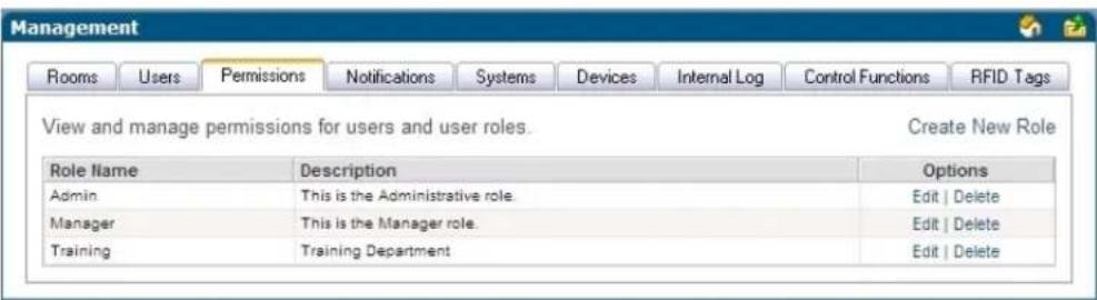
FIG. 79 Management - Permissions page
| Management - Permissions Page Options | |
| • Role Name | The friendly name of the security level or "role" within the RMS server. |
| • Description | A brief description of the role and the rights it holds. |
| • Options | Edit - Launches the Edit Role Page section on page 87.Delete - Deletes the selected role from the system. |
Create New Role
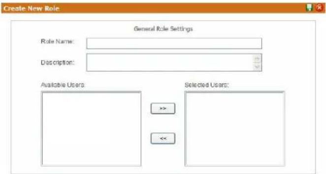
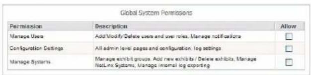
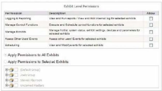

FIG. 80 Create New Role
| Create New Role options | |
| • Role Name | The friendly name of the security level or "role" within the RMS server. |
| • Description A brief description of the role and the rights it holds. | |
| • Available Users Users within the RMS application that can be added to the role. | |
| • Selected Users Users that have been added to the role. | |
| • << / >> Moves a selected user to the left and right adding or removing the user from the role. | |
| • Manage Users | When Allow is checked, users in this role can add, edit, and delete other users and how RMS interacts with those users, e.g., notifications. |
| • Configuration Settings | When Allow is checked, users in this role can access the configuration section of the Admin pages. Create and edit log settings. |
| • Manage Systems | When Allow is checked, users in this role can add, edit, and delete rooms, and manage NetLinx systems and groups. |
| • Logging & Reporting | When Allow is checked, users in this role can view and edit all logs and reports. |
| • Manage Control Functions | When Allow is checked, users in this role can run and schedule control functions. |
| Create New Role options (Cont.) | |
| · Manage Rooms | When Allow is checked, users in this role can manage the hotlist, system status, room settings, devices and parameters for the selected rooms. |
| · Access Other User's Appointments | When Allow is checked, users in this role can access another user's appointments for the selected rooms. |
| · Scheduling | When Allow is checked, users in this role can view and modify appointments for the selected rooms. |
| · Apply Permissions to All Rooms | When selected, applies all set permissions to every room within the RMS system. |
| · Apply Permissions to Selected Rooms | When selected, applies all set permissions to the rooms and groups selected in the list. |
Edit Role Page
The fields on the Edit Role page match those of the Create New Role page (see FIG. 80 on page 86).
- Any changes needed to be made to a preexisting user must be made in the Edit Role page.
- Once the user's information is in place, select the Save button to complete the changes.
Creating a New Role
- In the Management - Permissions Page, select Create New Role.
- In the Create New Role, type the name of role in Role Name.
- Type a brief description of the duties of this role in the space provided.
- Select the users in Available Users and click >> to add them to the role, Selected Users.
- Set the Global System Permissions.
- Set the Room Level Permissions.
- Apply the role permissions to either all rooms or select Apply Permissions to Selected Rooms, and select the rooms/groups from the list.
- Click Save to save, Cancel to cancel.
Editing a Role
- In the Management - Permissions Page, select Edit.
- In the Edit Role Page, edit the name of role in Role Name.
- Edit the brief description of the duties of this role in the space provided.
- Select the users in Available Users and click >> to add them to the role, Selected Users or vice versa to remove a user from the role.
- Revise the Global System Permissions.
- Revise the Room Level Permissions.
- Revise the role permissions to either all rooms or select Apply Permissions to Selected Rooms, and select the rooms/groups from the list.
- Click Save to save, Cancel to cancel.
Deleting a Role
In the Management - Permissions Page, select Delete.
Management - Notifications Page
The Management - Notifications page list allows you to configure notifications for your facility. Any user can be configured to receive notifications for any combination of groups, rooms and status types. Once a user has been created, notifications can be assigned.
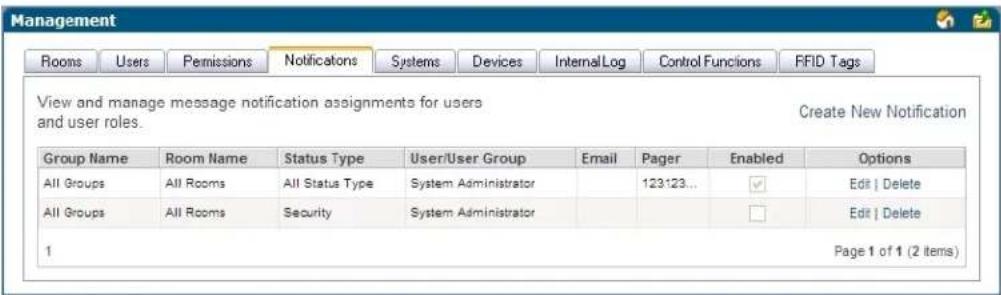
FIG. 81 Management - Notifications Page
| Management - Notifications Page Options | |
| · Group Name The group for this notification. | |
| · Room Name The room for this notification. | |
| · Status Type The Status Type for this notification. | |
| · User/User Group The user or group for this notification. | |
| · Email The user addresses for this notification. | |
| · Pager The user pager number for this notification. | |
| · Options | Edit - Launches the Edit Notification Page. Delete - Deletes the selected notification. |

For more information on creating users, see Creating a New User section on page 84.
See Also:
- Creating a New Group section on page 76 - monitor a group of rooms to utilize notifications.
- Creating a New Room section on page 81 - use notifications in conjunction with scheduling and monitoring rooms.
Create New Notification Page
Notifications are created via options in the Create New Notifications page (FIG. 82):
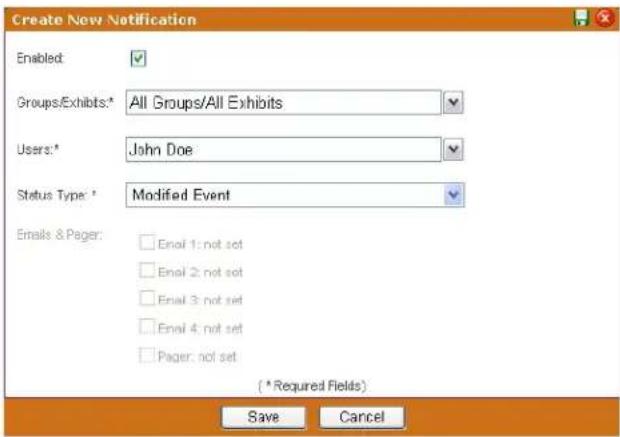
FIG. 82 Create New Notification Page
| Create New Notification Page Options | |
| • Enabled A check in this box activates the notification. | |
| • Group/Rooms | The group or rooms for this notification. You can select any one group to receive notification for all rooms contained in this group. This field is required |
| • Users | The user or role for this notification. This field is required |
| • Status Type The | Status Type for this notification. You can select one type or all types.Notifications can be configured beyond the standard Equipment Monitoring status types. These additional status types are:Control System Error- This status type is triggered when the RMS server detects an error within the NetLinx master control system.Equipment Usage- This status type is triggered when any monitored equipment is used.Help Request- This status type is triggered when the RMS server reports receiving a help request.Maintenance- This status type is triggered when the RMS server reports receiving a request for maintenance.Modified Appointment- This status type is triggered when an existing appointment is modified for a room either through the internal scheduler or as detected by the RMS Scheduling manager for an external scheduling system.Network- This status type is triggered when the network creates an error.New Appointment- This status type is triggered when a new appointment is added for a room either through the internal scheduler or as detected by the RMS Scheduling manager for an external scheduling system.New NetLinx System- This status type is triggered when a new NetLinx system connects to the RMS server.Not Assigned- This status type is triggered when a detected NetLinx system has not been assigned.Room Communication Error- This status type is triggered when the RMS server software encounters a problem communicating with a room within the RMS system.Security- This status type is triggered when the RMS server reports a security parameter has been met.Server Status- This status type is triggered when the RMS server software starts up.System Communication Error- This status type is triggered when the RMS server software encounters a problem communicating with an external communication system, such as SMTP or SNPP. This is a required field. |
| Email, Pager | The user addresses for this notification. Check the addresses which should be contacted for this notification. You can enter up to 100 characters for an email address. |
Edit Notification Page
You can only modify the delivery options of an existing notification.
Edit Notification
| • Enabled A check in this box activates the notification. | |
| • Users The user or role for this notification. This field is required | |
| • Email, Pager | The user addresses for this notification. Check the addresses which should be contacted for this notification. You can enter up to 100 characters for an email address. |
Creating a Notification
- In the Management - Notifications Page, select Create New Notification. The Create New Notification page (FIG. 82 on page 89) opens.
- Check the box next to Enabled to activate the notification.
- Set the Groups/Rooms value for the notification. Select a group of rooms, a single room or all groups and rooms in the RMS system from the drop-down combo box. This field is required.
- Set the Users value for the notification. Select a role or individual user in the RMS system from the dropdown combo box. This field is required.
- Set the Status Type value for the notification. Select all status types or designate a specific status from the drop-down combo box. This field is required.
-
Select the delivery method for the notification. Place a check in each box to enable that option. These values correspond to those set for each user in RMS.
-
Click Save.
Editing a Notification
Security settings dictate your ability to add/modify/delete notifications for anyone or yourself.
-
In the Management - Notifications Page, select Edit. The Edit Notifications page opens.
-
Edit any of the following:
-
Check the box next to Enabled to activate the notification.
- Set the Groups/Rooms value for the notification. Select a group of rooms, a single room or all groups and rooms in the RMS system from the drop-down combo box. This field is required.
- Set the Users value for the notification. Select a role or individual user in the RMS system from the drop-down combo box. This field is required.
- Set the Status Type value for the notification. Select all status types or designate a specific status from the drop-down combo box. This field is required.
-
Select the delivery method for the notification. Place a check in each box to enable that option. These values correspond to those set for each user in RMS.
-
Click Save to save, Cancel to cancel.
Deleting a Notification
In the Management - Notifications Page, select Delete for the selected notification.

Security settings dictate your ability to add/modify/delete notifications for anyone or yourself.
Changing the Domain Path For Notifications
By default, when a notification is sent out the link does not utilize the fully qualified domain name. You can change the domain path such that those outside of the immediate network can use the link. To change the host name:
- Stop all RMS services.
- Run C:\Program Files\ AMX Resource Management Suite\Scripts\RMS Hostname.vbs
- Click Yes.
- Enter the new hostname, e.g., rms.my-domain.com
- Click OK.
- Restart RMS services.
Management - Systems Page
The Management - Systems page allows you to browse the NetLinx masters connected to the RMS application and inspect their configuration.
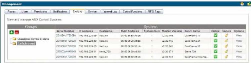
FIG. 83 Management - Systems Page
| Management - Systems Page Options | |
| • Serial Number Serial Number associated with the room. | |
| • IP Address IP Address associated with the room. | |
| • Host Name Host Name associated with the room. | |
| • MAC Address The MAC address associated with the room. | |
| • System Number This is the system number of the NetLinx master. The system number is used in master-to-master configuration. | |
| • Master Version This is the firmware version of the NetLinx master. | |
| • Room Name The friendly name of the room in the event the NetLinx system is connected to the RMS application. | |
| • Online Displays w whether this NetLinx system is connected to the RMS application. | |
| • Secure | This displays a locked icon if both the Telnet and HTTP server are not open to anonymous access.Note: An unlock icon means one or both of these services is available to any user. |
| • View | This button provides more details on the NetLinx masters configuration. Launches the View System Page. |

NOTE
This table can be sorted by Serial Number, IP Address, Host Name, System Number, Module Name, Master Version, and System Online.
View System Page
Use the View System page to view details on each system listed in the Management - Systems page.
| View System Page | |
| System Information | |
| • Module Name This | is the name of the module on the NetLinx master. |
| • Master Version This | is the firmware version of the NetLinx master. |
| • Master Type The m | odel number of this master. |
| • System Number This | is the system number of the NetLinx master. The system number is used in master-to-master configuration. |
| • Serial Number This | is the serial number of the NetLinx master. |
| • ICSP Port This is the IP port currently used for ICSP communications. The default is 1319. | |
| • Telnet Port | This is the IP port currently used for Telnet communication. The default port is 23. |
| • Telnet Security Enabled | The state of the telnet security settings |
| • HTTP Port | This is the IP port currently used for HTTP communication. The default port is 80. |
| • HTTP Security Enabled | The state of the HTTP security settings |
| • Supports Welcome Images | This indicates if the NetLinx masters support Welcome Images. Specifically, this value is set when a G4 panel, which supports Welcome Images, has been added and programmed to display Welcome Images. |
| • Can be Assigned to Room | This indicates whether the NetLinx master can be assigned to a room. If this value is set to NO, the NetLinx master will not appear in the list of available system in Add Room. |
| • RMS SDK Version | This is the version of RMS code running in the NetLinx system. |
| • RMS SDK Description | This is the description of the RMS code running in the NetLinx system. |
| IP Configuration | |
| • DHCP/Static Indicates the NetLinx master's IP address configuration type, either DHCP or static. | |
| • IP Address• Subnet Mask• Gateway• DNS List• Host Name• MAC Address | These are the IP settings of the NetLinx master.These values are the current settings of the master and are displayed whether the NetLinx master's IP address configuration is set for DHCP or Static. |
| IP Connection | |
| Connected From | The IP address the NetLinx system is using to connect to the RMS application.Normally, this is the same as the IP address with which the NetLinx system is configured. However, if the NetLinx system is behind a firewall or a router that provide NAT services, this IP address may be different than that above. |
| Connect via HTTP/FTP/Telnet | These links will open either a HTTP, FTP or Telnet window to the NetLinx master. These links can provide a quick way to modify a master configuration or view other information. |
- View Room - Launches the View Room Settings Page section on page 79.
● Control Functions - Launches the Execute Control Function Page section on page 64.
Viewing a System
- Select Management > Systems in the menu on the left side of the RMS application.
- Select the system you wish to view by either clicking the Serial Number or View. The View System page opens.
Management - Devices Page
The Management - Devices page enables you to enter device information for a monitored device or search for an existing device (FIG. 84).
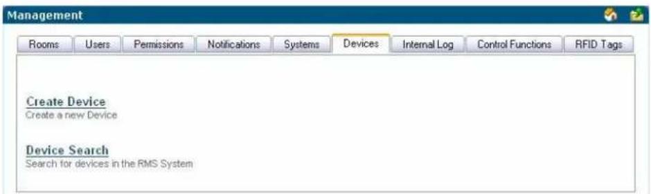
FIG. 84 Management - Devices Page
Create Device Page
Select Create Device in the Management - Devices Page to access the Create Device page (FIG. 85):
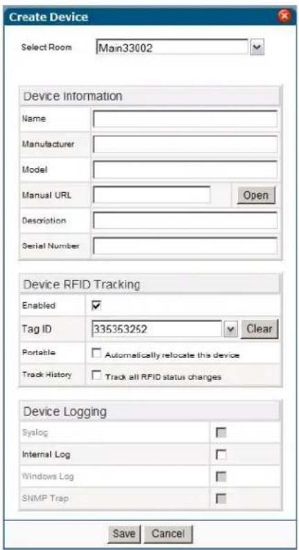
FIG. 85 Create Device Page
| Create Device | |
| • Select Room | Allows you to select an existing room in which the device currently resides. Note: This option only appears when you access this page via the option on the menu or by clicking Create Device on the Devices tab. If you use the Create Device option on the Rooms Devices page, RMS assumes you are creating the device in that room |
| • Name The name of the monitored device. | |
| • Manufacturer The manufacturer of the monitored device. | |
| • Model The model of the monitored device. | |
| • Manual URL A URL link to the manual on the manufacturer's web site. | |
| • Description A description of the monitored device. | |
| • Serial Number The serial number of the monitored device. | |
| • Enabled Allows you to enable or disable RFID tracking for the device. | |
| • Tag ID Allows you to enter the RFID tag ID for the device. | |
| • Portable | Allows you to enable or disable the RFID automatic location tracking for the device. |
| • Track History Allows you to enable or disable the RFID tracking history for the device. | |
| • Syslog | Allows you to turn on the system log for the device. |
| • Internal Log | Allows you to turn on the internal log for the device. |
| • Windows Log | Allows you to turn on the Windows log for the device. |
| • SNMP Trap | Allows you to turn on the SNMP trap log for the device. |
Device Search Page
Select Device Search in the Management - Devices Page to access the Device Search page (FIG. 86):
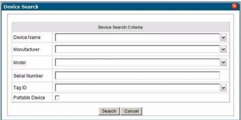
FIG. 86 Device Search Page
| Device Search Page Options | |
| • Device Name | The name of the monitored device. |
| • Manufacturer | The manufacturer of the monitored device. |
| • Model | The model of the monitored device. |
| • Serial Number | The serial number of the monitored device. |
| • Tag ID | The RFID tag ID of the monitored device. |
| • Portable Device Only | Allows you to indicate whether the monitored device is portable and can be moved to another room. |
You can select an item from one or more of the search criteria to perform your search. The results of your search appear in the Device Search Result page (FIG. 87).
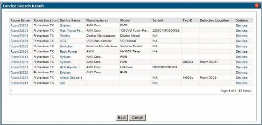
FIG. 87 Device Search Result Page
Management - Internal Log Page
The Internal Log displays parameter changes that reached their thresholds for devices that are configured to report to the Internal Log. The Internal Log is a historical record of all faults on the RMS application system.
The Internal Log can be exported and saved on the server in a Comma Separated Value (CSV) formatted text file. This file can then be imported and formatted using other tools, such as Microsoft Excel®.
The exported log files currently on the server are displayed on the Management - Internal Log page (FIG. 88).
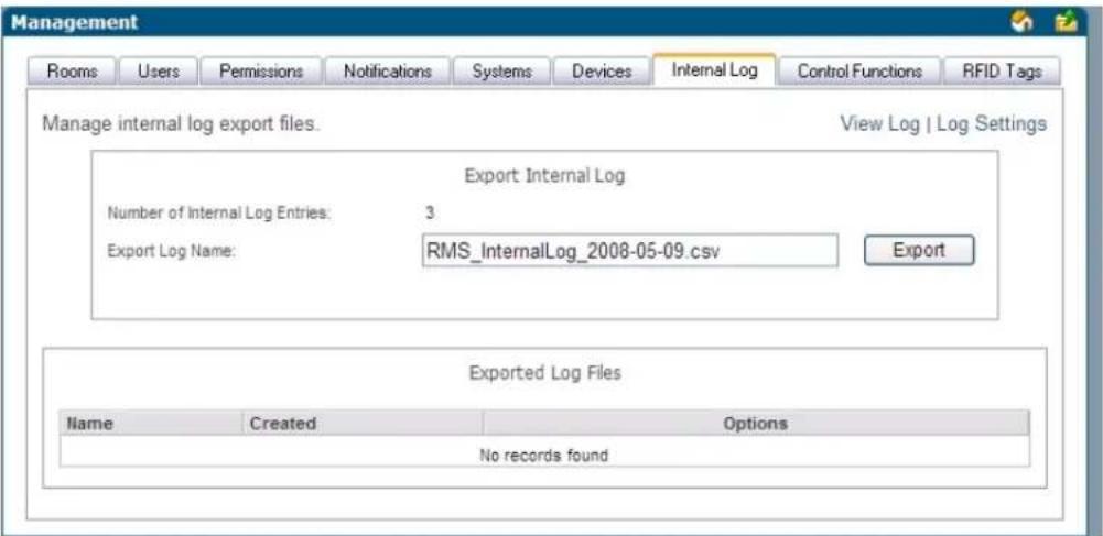
FIG. 88 Management - Internal Log Page
| Management - Internal Log Page Options | |
| Number of Internal Log Entries | The number of Internal Log entries in the report for export. |
| Export Log Name This file is stored on the server and can be downloaded and deleted. | |
| Export Exports current log entry. | |
| Name Name of the previously exported log file. | |
| Created The date the exported file was created. | |
| Options | View - Launches the Internal Log Report Page section on page 148.Delete - Deletes the CSV file. |
See Also...
● Internal Log Report Page section on page 148
- Configure Internal Log Page section on page 154
Exporting an Internal Log
- In the Management - Internal Log page, name your internal log file in the Export Log Name field.
- Click Export.
Viewing Exported Internal Logs
- In the Management - Internal Log page, locate your log file (in the Exported Log Files section)
- Click View.
Deleting Exported Internal Logs
- In the Management - Internal Log page, locate your log file (in the Exported Log Files section)
- Click Delete.
Management - Control Functions Page
The RMS application allows you to create control function (macros) that can be assigned to rooms and groups and scheduled to execute at specific times.

Control Function macros are a collection of ConnectLinx actions.
Control Functions are managed via options in the Management - Control Functions page (FIG. 89):
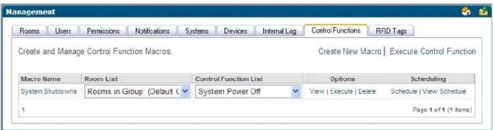
FIG. 89 Management - Control Functions Page
| Management - Control Functions Page Options | |
| • Macro Name The friendly name of the macro. | |
| • Room List A drop down list of the rooms associated with the macro. | |
| • Control Function List A drop down list of the control functions associated with the macro. | |
| • Options | • View - Launches the Edit Macro Page section on page 98.• Execute - Executes the selected macro.• Delete - Deletes the selected macro. |
| • Scheduling | • Schedule - Launches the Schedule Macro Page section on page 98.• View Schedule - Launches the Control Function Macro Schedules Page. |
Create Control Function Macro Page
Use the options in the Create Control Function Macro page (FIG. 90) to create your own macros where you establish which rooms are affected and what actions are taken.
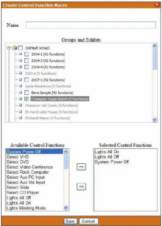
FIG. 90 Create Control Function Macro Page
| Create Control Function Macro Page Options | |
| • Name The friendly name of the macro. | |
| • Groups and Rooms A checkbox list of rooms and groups of rooms detected by RMS. | |
| • Available Control Functions | A list of ConnectLinx control functions for each device found in the room. If more than one room or group is selected, only functions common throughout all the selected rooms are displayed in this field. |
| • Selected Control Functions | The list of selected ConnectLinx control functions that will make up the macro. |
| • << / >> Moves a selected control function to the left and right adding or removing it from the macro list. | |
Edit Macro Page
The fields on the Edit Macro page match those of the Create Control Function Macro page (FIG. 90 on page 97). The options in the Edit Macro page allow you to add and remove rooms, groups and macros from an existing Control Function macro.
Schedule Macro Page
After you have created a Control Function macro you can schedule when it executes and opt to define it as being recurring, via options in the Schedule Macro page (FIG. 91).
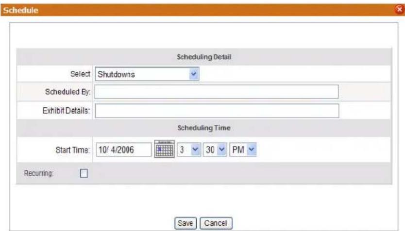
FIG. 91 Schedule Macro Page
| Schedule Macro Page Options | |
| Select Macro: A | drop down list of available macros. |
| Scheduled By: | The user who has scheduled the macro to execute. |
| Subject: | A text field to provide descriptive information about why this macro has been scheduled. |
| Start Time: | A text field for the date (mm/dd/yyyy) the macro has been scheduled. You can click on the calendar icon to select the date. The three following drop-down combo boxes represent hour, minute, and designation for ante-meridiem vs. post-meridiem (AM/PM), in that order. |
| Enabled: | Make recurring - When checked, this option makes the scheduled macro a recurring event. |
| Pattern:Daily Makes the | recurring scheduled macro a daily pattern.Every _ days(s) - text field for number of days between daily recurring macroEvery weekday - executes the daily macro only Monday - Friday. |
| Weekly Makes | the recurring scheduled macro a weekly pattern.Every _ week(s) - text field for number of weeks between weekly recurring macroSelect the day the weekly scheduled macro is to execute; more than one day can be selected. |
| Monthly Makes | the recurring scheduled macro a monthly pattern.Day _ of every _ month(s) - the drop-down combo boxes allow you to set what day of the month the recurring macro executes and the number of months between each execution.The _ of every _ month(s) - this setting allows you to pick either the first, second, third, fourth, or last day of the week and the number of months between each execution. |
| Schedule Macro Page Options (Cont.) | |
| Yearly Makes the recurring scheduled macro a yearly pattern.Every__ _ - the drop-down combo boxes allow you to set the month and day the recurring macro executes.The__ of - this setting allows you to pick either the first, second, third, fourth, or last day of the week of a specified month. | |
| • Lifetime:No end date The scheduled recurring macro does not end. | |
| End after occurrences | The scheduled recurring macro ceases to run upon reaching the user defined parameter. |
| End by: | Either type the date the scheduled recurring macro is to end or select the date from the calendar icon. |
Control Function Macro Schedules Page
The Control Function Macro Schedules page lists all scheduled Control Function macros (FIG. 92).
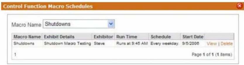
FIG. 92 Control Function Macro Schedules Page
| Control Function Macro Schedules Page Options | |
| Select Macro | The friendly name of the macro. Select a specific macro from the drop down list to or select All Macros to display all scheduled macros. |
| Macro Name | The friendly name of the selected macro. |
| Subject | A text field to provide descriptive information about why this macro has been scheduled. |
| Organizer The | user who has scheduled the macro to execute. |
| Run Time The | time the macro is scheduled to run. |
| Schedule The | frequency with which the macro executes. |
| Start Date The | beginning date for the scheduled macro. |
| View | Launches the Schedule Macro Page. |
| Delete | Deletes the macro from the schedule. |
Creating a New Macro
- In the Management - Control Functions page (FIG. 89 on page 96), click Create New Macro. The Create Control Function Macro page opens.
- Name the macro in the field Name.
- Select the rooms and or groups included in the macro; this is done by placing a check in the box next to the group or room. Double-click groups to expand them.
-
The Available Control Functions window is populated by device control functions associated to your selected room. In the event you have more than one room selected, only functions that are shared in all rooms are shown.
-
Select a control function and move it to the Selected Control Functions window by clicking the << button.
-
Repeat as necessary.
-
Click Save to save, Cancel to cancel.
Viewing a Macro
- In the Management - Control Functions page (FIG. 89 on page 96), locate your macro and click View. The Edit Macro page opens.
-
Edit any of the following:
-
Rename the macro in the Name field.
- Select or deselect the rooms and or groups included in the macro; this is done by placing a check in the box next to the group or room (include). Removing the check in the box next to the group or room (remove). Double-click groups to expand them.
- The Available Control Functions window is populated by device control functions associated to your selected room. In the event you have more than one room selected, only functions that are shared in all rooms are shown.
Select a control function and move it to the Selected Control Functions window by clicking the >> button. Repeat as necessary.
- To remove a function, select a control function in the Selected Control Functions window and move it to the Available Control Functions window by clicking the << button. Repeat as necessary.
- Click Save.
Executing a Macro
In the Management - Control Functions page (FIG. 89 on page 96), find your macro, and click Execute.
Deleting a Macro
In the Management - Control Functions page (FIG. 89 on page 96), find your macro, and click Delete.
Scheduling a Macro
- In the Management - Control Functions page (FIG. 89 on page 96), find your macro, and click Schedule. The Schedule Macro page opens.
- Confirm the selected macro is listed in the Select Macro drop-down combo box.
- Type the name or title of the person scheduling the macro in the Scheduled By field.
- Type a brief description or explanation in the Subject field.
- Set the Start Time for the macro.
- If this a recurring macro, check the box next to Recurring to enable and continue; otherwise, you can click Save or Cancel.
- Set the Pattern for the macro.
- Set the Lifetime for the macro.
- Click Save.
Viewing a Macro Schedule
- In the Management - Control Functions page (FIG. 89 on page 96), find your macro, and click View Schedule. The Control Function Macro Schedules page opens.
- Confirm the selected macro is listed in the Macro Name drop-down combo box.
Management - RFID Tags Page
RFID tags are managed via options in the Management - RFID Tags page (FIG. 93):
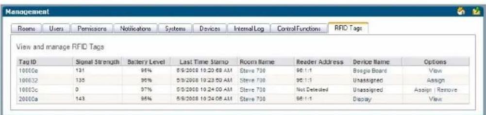
FIG. 93 Management - RFID Tags page
| Management - RFID Tags Page Options | |
| • Tag ID | The numerical identification tag. Opens the Tag Details page (see the Tag Details Page section on page 101 for more information.) |
| • Signal Strength The | tag ID's current signal strength, reported as a percentage. If an RFID reader cannot detect the RFID tag, the field displays a level of 0%. |
| • Battery Level The | percentage of power remaining in the RFID tag's battery. If an RFID reader cannot detect the RFID tag, the field displays the tag's last known battery level. |
| • Last Time Stamp The | the last update to the tag ID's information. |
| • Room Name | The room assigned to the RFID tag. Opens the View Room Settings page (see the View Room Settings Page section on page 79 for more information.) |
| • Reader Address The | address of the RFID reader. |
| • Device Name The type of device assigned to the RFID tag. | |
| • Options | Assign - Enables you to assign the RFID tag to a device. Opens the Assign Tag to Device page (see the Assign Tag to Device Page section on page 102 for more information.)Remove - Removes the RFID tag from the list.View - Enables you to view and edit the device assigned to the RFID tab. This option opens the Device Information page (see the Create Device Page section on page 93 for more information.) |
| • Detected Location | The current location of the device. |
Tag Details Page
The Tag Details page (FIG. 94) displays information about the RFID tag including the Room Name, Reader Address, and Signal Strength of the tag. This information is view-only.
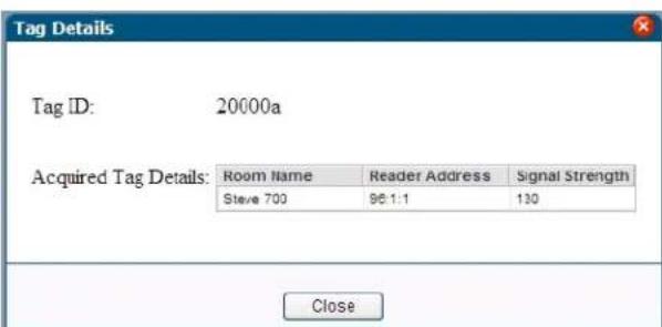
FIG. 94 Tag Details Page
Assign Tag to Device Page
Click Assign on the Management - RFID Tags page to assign a device to an RFID tag, via the Assign Tag to Device page (FIG. 95). Use the options on this page to select the appropriate Room and Device to assign to the selected RFID tag.
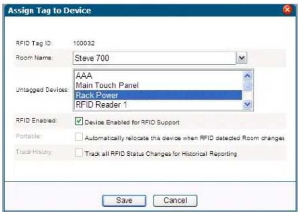
FIG. 95 Assign Tag to Device page
| Assign Tag to Device Page Options | |
| RFID Tag ID The RFID tag ID for the targeted device. This option is read-only. | |
| Room Name A list of available rooms in the RMS system with Asset licenses.The default value for the room is the current room in which the RFID reader detects the RFID tag. | |
| Untagged Devices A list of untagged devices in the room.The listing displays all devices located in the currently selected room that do not have RFID tags assigned to them.If you change the room selection, the device listing repopulates with updated device data. | |
| RFID Enabled Allows you to enable RFID tracking for the target device. | |
| Portable | Allows you to enable the RFID automatic location tracking for the target device. |
| Track History Allows you to enables RFID tracking history for the target device.Note:This option is only available if you enable the global system RFID History Tracking option in the RMS Configuration Wizard. | |
Reporting Page
System Reports Page
The RMS applications support a variety of different reports designed to help you diagnose and improve the user's experience with the system network.
The system reports are organized into the following categories:
- Room Reports
- Power Reports
• Quality of Service Reports - Organizer Reports
Each report is rendered and displayed on the Report View page. While the information varies based on the report run, your options are always the same. You can output the report the following ways.
FIG. 96 Report Output Options
- Generates a PDF version of the report.
- Generates a Excel version of the report.
- Generates a HTML version of the report.
- Generates a Word version of the report.
- Prints the report.

Popup pages must be enabled on the web browser to export or print system reports.
Room Reports
System Reports - Help Requests
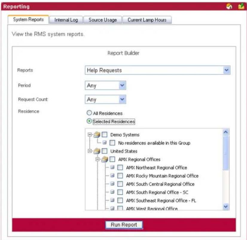
FIG. 97 System Reports - Help Requests
This report provides a count of all help requests entered by an organizer within the parameters designated.
| System Reports - Help Requests | |
| • Period | The time parameter the report is to run within. Click the calendar(s) to select a date; otherwise, type the date in the field provided.• On/After - Selects all instances on or after the designated date.• On - Selects all instances on the designated date.• On/Before - Selects all instances on or before the designated date.• Between - Selects all instances between the designated dates.• Any - Selects all instances. |
| • Options Request Count:• >= - Selects all instances that are greater than and equal to the number you place in the field.• = - Selects all instances that are equal to the number you place in the field.• <= - Selects all instances that are less than and equal to the number you place in the field.• Between - Selects all instances that are greater than and equal to the number you place in the field but less than and equal to the other number.• Any - Selects all instances. | |
| • Residence | Select either All Residences or Selected Residences. The latter provides a list of rooms and groups available within the RMS system. |
| • Run Report | Generates the report. |
System Reports - Help Requests Results
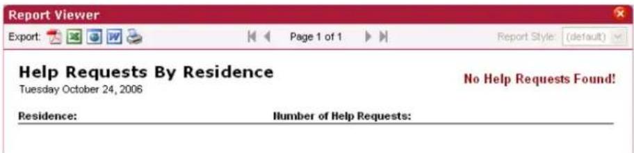
FIG. 98 Help Requests Results
| Help Requests Results | |
| • Residence The rooms where the requests occurred. | |
| • Number of Help Requests | The number of request instances within the designated parameters. |
System Reports - Help Requests (Detailed)
This report provides a list of all help requests entered by an organizer within the designated parameters plus the qualifier Request like (FIG. 99).

FIG. 99 Help Requests (Detailed)
| Help Requests (Detailed) | |
| • Period | The time parameter the report is to run within. Click the calendar(s) to select a date; otherwise, type the date in the field provided.• On/After - Selects all instances on or after the designated date.• On - Selects all instances on the designated date.• On/Before - Selects all instances on or before the designated date.• Between - Selects all instances between the designated dates.• Any - Selects all instances. |
| • Options | Request like - A keyword search for specific requests. |
| • Residence | Select either All Residences or Selected Residences. The latter provides a list of rooms and groups available within the RMS system. |
| • Run Report | Generates the report. |
System Reports - Help Requests (Detailed) Results
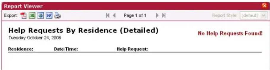
FIG. 100 System Reports - Help Requests (Detailed) Results
| System Reports - Help Requests (Detailed) Results | |
| • Residences The rooms where the requests occurred. | |
| • Date/Time The date and time the request occurred. | |
| • Help Request The help request that occurred. |
System Reports - Residence Usage
This report provides the number of hours all rooms included in the report have been scheduled via the RMS application's scheduling feature within the parameters specified (FIG. 101). If the scheduling features of the RMS application are not being used, this report will not contain any useful data.
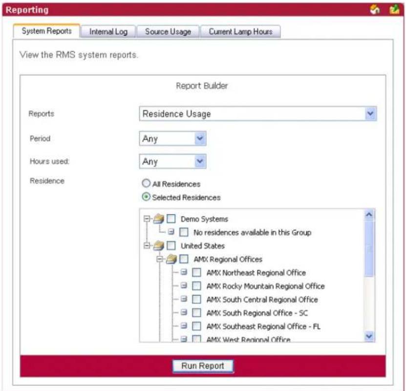
FIG. 101 System Reports - Residence Usage
| System Reports - Residence Usage | |
| • Period The time parameter the report is to run within. Click the calendar(s) to select a date; otherwise, type the date in the field provided.• On/After - Selects all instances on or after the designated date.• On - Selects all instances on the designated date.• On/Before - Selects all instances on or before the designated date.• Between - Selects all instances between the designated dates.• Any - Selects all instances. | |
| • Options Hours used:• >= - Selects all instances that are greater than and equal to the number you place in the field.• = - Selects all instances that are equal to the number you place in the field.• <= - Selects all instances that are less than and equal to the number you place in the field.• Between - Selects all instances that are greater than and equal to the number you place in the field but less than and equal to the other number.• Any - Selects all instances. | |
| • Residence | Select either All Residences or Selected Residences. The latter provides a list of rooms and groups available within the RMS system. |
| • Run Report | Generates the report. |
System Reports - Residence Usage Results
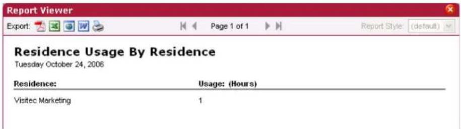
FIG. 102 System Reports - Residence Usage Results
| System Reports - Residence Usage Results | |
| • Residence | The rooms being tracked for usage. |
| • Usage The | amount of time, in hours, the room has been in use. |
System Reports - Source Usage
This report provides the number of hours an organizer has used a source within any given room and any number of sources available (FIG. 103).
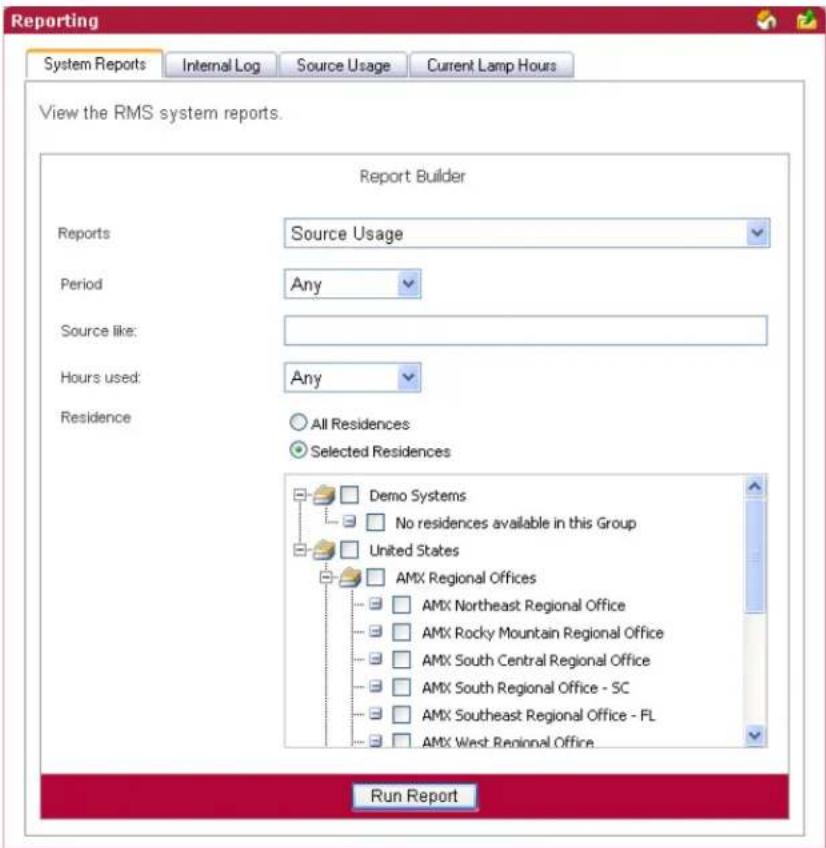
FIG. 103 System Reports - Source Usage
| System Reports - Source Usage | |
| • Period The time parameter the report is to run within. Click the calendar(s) to select a date; otherwise, type the date in the field provided.• On/After - Selects all instances on or after the designated date.• On - Selects all instances on the designated date.• On/Before - Selects all instances on or before the designated date.• Between - Selects all instances between the designated dates.• Any - Selects all instances. | |
| • Options | • Source like - A keyword search for specific source items.Hours used:• >= - Selects all instances that are greater than and equal to the number you place in the field.• = - Selects all instances that are equal to the number you place in the field.• <= - Selects all instances that are less than and equal to the number you place in the field.• Between - Selects all instances that are greater than and equal to the number you place in the field but less than and equal to the other number.• Any - Selects all instances. |
| • Residence | Select either All Residences or Selected Residences. The latter provides a list of rooms and groups available within the RMS system. |
| • Run Report | Generates the report. |
System Reports - Source Usage Results
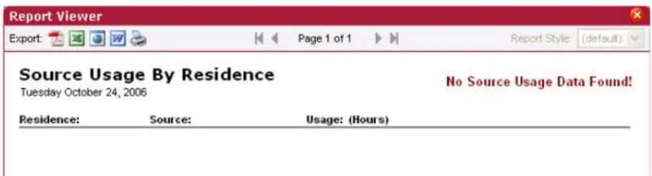
FIG. 104 System Reports - Source Usage Results
| System Reports - Source Usage Results | |
| • Room The rooms being tracked for usage. | |
| • Source The source in use. | |
| • Usage The amount of time, in hours, the source has been in use. |
System Reports - Cumulative Lamp Hours
This report provides the number of hours a projector lamp was powered on within the designated parameters for all rooms included in the report. (FIG. 105)
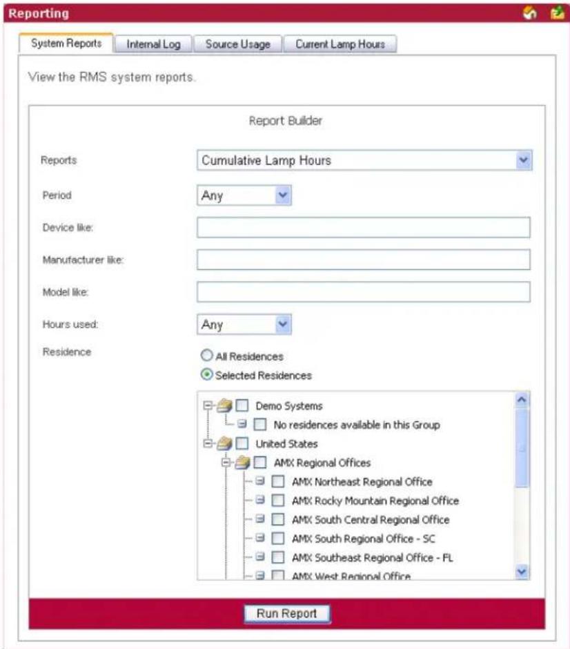
FIG. 105 System Reports - Cumulative Lamp Hours
| System Reports - Cumulative Lamp Hours | |
| • Period | The time parameter the report is to run within. Click the calendar(s) to select a date; otherwise, type the date in the field provided.• On/After - Selects all instances on or after the designated date.• On - Selects all instances on the designated date.• On/Before - Selects all instances on or before the designated date.• Between - Selects all instances between the designated dates.• Any - Selects all instances. |
| System Reports - Cumulative Lamp Hours (Cont.) | |
| Options | Device like - A keyword search for specific device items.Manufacturer like - A keyword search for specific manufacturer name.Model like - A keyword search for specific model type.Hours used:>= - Selects all instances that are greater than and equal to the number you place in the field.= - Selects all instances that are equal to the number you place in the field.<= - Selects all instances that are less than and equal to the number you place in the field.Between - Selects all instances that are greater than and equal to the number you place in the field but less than and equal to the other number.Any - Selects all instances. |
| Residence | Select either All Residences or Selected Residences. The latter provides a list of rooms and groups available within the RMS system. |
| Run Report | Generates the report. |
System Reports - Cumulative Lamp Hours Results
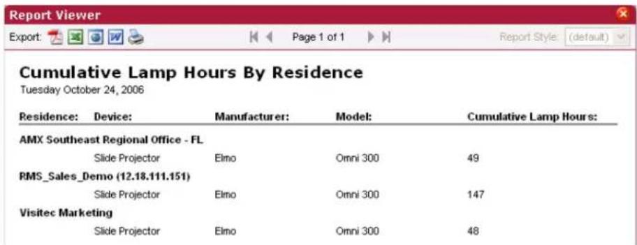
FIG. 106 System Reports - Cumulative Lamp Hours Results
| System Reports - Cumulative Lamp Hours Results | |
| • Residence The rooms being tracked for usage. | |
| • Device The device in use. | |
| • Manufacturer The manufacturer name of the device. | |
| • Model The model of the device. | |
| • Cumulative Lamp Hours | The combined number of hours used by every lamp ever installed on the projector.If the projector has had 2 lamps replaced, each with 100 hours usage, and the currently installed lamp has 50 hours of usage then the cumulative total will be 250 hours.When a lamp is replaced the usage of the previously-installed lamp is zeroed out by a negative value equivalent to the total number of hours used by the previous (replaced) lamp being written into the parameter history table (tblDeviceParameterValues). The reports take this into consideration and ignore negative delta values in summations. |
System Reports - Transport Run Time
This report provides the number of hours a transport device was running between the start and end dates for all rooms included in the report (FIG. 107).
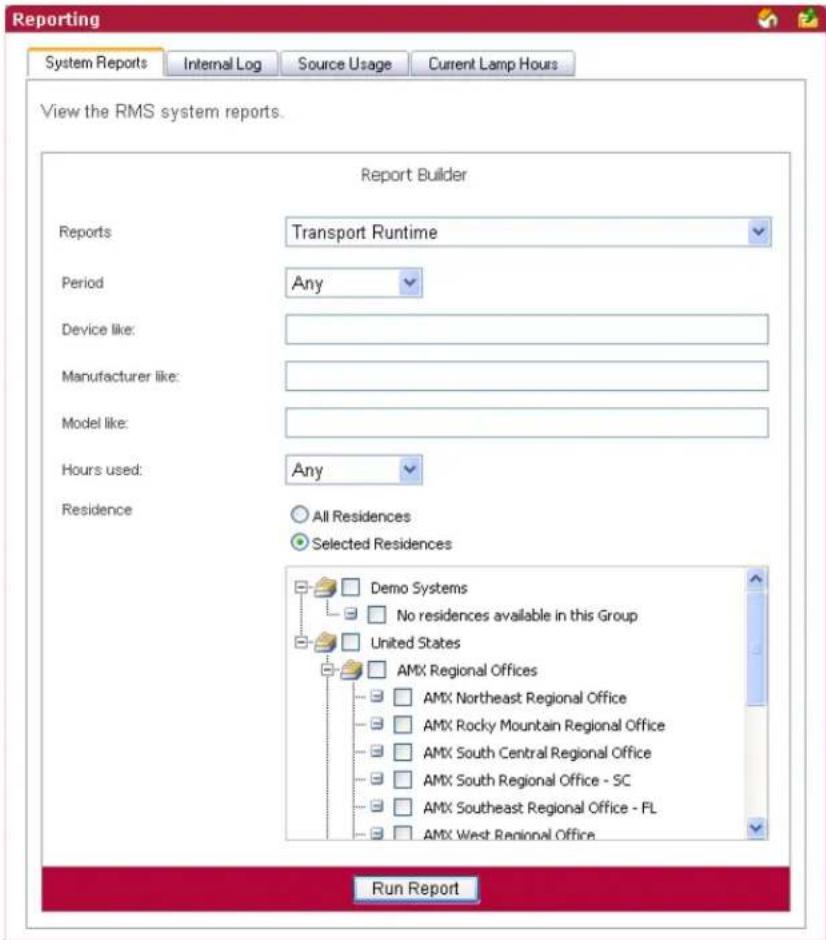
FIG. 107 System Reports - Transport Run Time
| System Reports - Transport Run Time | |
| • Period | The time parameter the report is to run within. Click the calendar(s) to select a date; otherwise, type the date in the field provided.• On/After - Selects all instances on or after the designated date.• On - Selects all instances on the designated date.• On/Before - Selects all instances on or before the designated date.• Between - Selects all instances between the designated dates.• Any - Selects all instances. |
| System Reports - Transport Run Time (Cont.) | |
| Options | Device like - A keyword search for specific device items.Manufacturer like - A keyword search for specific manufacturer name.Model like - A keyword search for specific model type.Hours used:>= - Selects all instances that are greater than and equal to the number you place in the field.= - Selects all instances that are equal to the number you place in the field.<= - Selects all instances that are less than and equal to the number you place in the field.Between - Selects all instances that are greater than and equal to the number you place in the field but less than and equal to the other number.Any - Selects all instances. |
| Residence | Select either All Residences or Selected Residences. The latter provides a list of rooms and groups available within the RMS system. |
| Run Report | Generates the report. |
System Reports - Transport Run Time Results
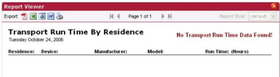
FIG. 108 System Reports - Transport Run Time Results
| System Reports - Transport Run Time Results | |
| • Residence The rooms being tracked for usage. | |
| • Device The device in use. | |
| • Manufacturer The manufacturer name of the device. | |
| • Model The model of the device. | |
| • Run Time The amount of time, in hours, the transport device has been in use. |
System Reports - Current Source Usage
This report provides all of the data found on the Source Usage viewing page in the RMS web user interface (FIG. 109).
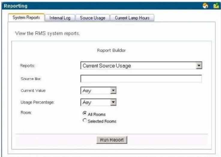
FIG. 109 System Reports - Current Source Usage
| System Reports - Current Source Usage | |
| Options | Source Device Name like - A keyword search for a specific source device name.Current Value and Usage Percentage:>= - Selects all instances that are greater than and equal to the number you place in the field.= - Selects all instances that are equal to the number you place in the field.<= - Selects all instances that are less than and equal to the number you place in the field.Between - Selects all instances that are greater than and equal to the number you place in the field but less than and equal to the other number.Any - Selects all instances. |
| Residence | Select either All Residences or Selected Residences. The latter provides a list of rooms and groups available within the RMS system. |
| Run Report | Generates the report. |
System Reports - Current Source Usage Results
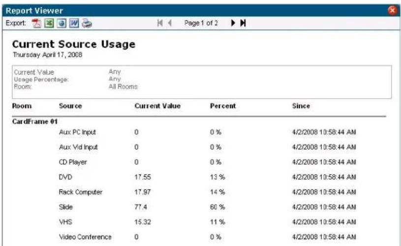
FIG. 110 System Reports - Current Source Usage Results
| System Reports - Current Source Usage Results | |
| • Room Name of the room. | |
| • Source Name of the source. | |
| • Current Value | Usage, in hours, of the source since date/time listed inSincecolumn |
| • Percent | Percentage of the total system usage this represents based on systems power since the date/time in the Since column. |
| • Since Date/Time this value was last reset. | |
System Reports - Current Lamp Hour
This report provides all of the data found on the Current Lamp Hours viewing page in the RMS web user interface (FIG. 111).
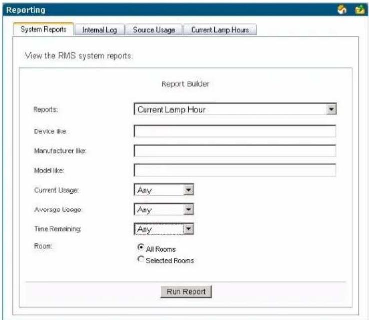
FIG. 111 System Reports - Current Lamp Hour
| System Reports - Current Lamp Hour | |
| Options | Device Name like - A keyword search for a specific device name.Device Model like - A keyword search for a specific device model.Manufacturer like - A keyword search for a specific device manufacturer.Usage - The total usage in hours for the currently installed lamp.Lamp Life - The user-defined lifetime of the currently installed lamp.Average Usage - The average usage is calculated by dividing the total number of hours for every lamp ever used on the projector by the number of days in the sampling period. In the case of this report the sampling period is the entire lifetime of the device.Time Remaining - Using the above definitions, Time Remaining = Usage subtracted from Lamp Life.Current Usage, Average Usage, and Time Remaining:>= - Selects all instances that are greater than and equal to the number you place in the field.= - Selects all instances that are equal to the number you place in the field.<= - Selects all instances that are less than and equal to the number you place in the field.Between - Selects all instances that are greater than and equal to the number you place in the field but less than and equal to the other number.Any - Selects all instances. |
| Residence | Select either All Residences or Selected Residences. The latter provides a list of rooms and groups available within the RMS system. |
| Run Report | Generates the report. |
System Reports - Current Lamp Hours Results
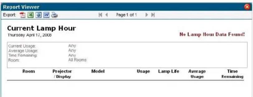
FIG. 112 System Reports - Current Lamp Hours Results
| System Reports - Current Lamp Hours Results | |
| • Room The friendly | name for the room to which the monitored device is associated. |
| • Projector/Display | Name of the projector. |
| • Model Manufacturer | and Model of projector. |
| • Usage Number of | hours on the lamp. |
| • Lamp Life | Expected lamp life set in the RMS application. This is the threshold of the Lamp Hours parameter. |
| • Average Usage Average use in Hours/Day based on historical data in the RMS application. | |
| • Time Remaining | Estimated time remaining in days on the lamp based on the expected lamp life and average usage per day.If the lamp is past the established threshold, it displaysReplace Lampin red.If there are 14 days or less left on the lamp, it is displayed in orange.If there are 7 or less days left on the lamp, it is displayed in red. |
Power Reports
Power Reports - System Power
This report provides the number of hours each system has been powered on within the parameters for all rooms included in the report.
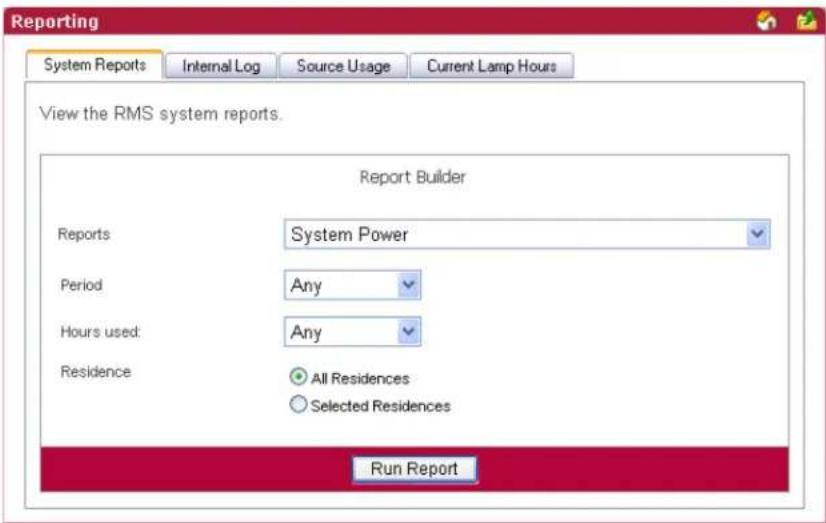
FIG. 113 Power Reports - System Power
| Power Reports - System Power | |
| • Period | The time parameter the report is to run within. Click the calendar(s) to select a date; otherwise, type the date in the field provided.• On/After - Selects all instances on or after the designated date.• On - Selects all instances on the designated date.• On/Before - Selects all instances on or before the designated date.• Between - Selects all instances between the designated dates.• Any - Selects all instances. |
| • Options Hours used:• >= - Selects all instances that are greater than and equal to the number you place in the field.• = - Selects all instances that are equal to the number you place in the field.• <= - Selects all instances that are less than and equal to the number you place in the field.• Between - Selects all instances that are greater than and equal to the number you place in the field but less than and equal to the other number.• Any - Selects all instances. | |
| • Residence | Select either All Residences or Selected Residences. The latter provides a list of rooms and groups available within the RMS system. |
| • Run Report Generates the report. | |
Power Reports - System Power Results
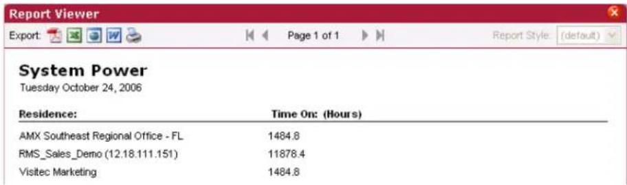
FIG. 114 System Power Results
| System Power Results | |
| • Residence The rooms being tracked for usage. | |
| • Time On (Hours) The amount of time, in hours, the system has been in use. |
Power Reports - Device Power
This report provides the number of hours a device has been powered on within the parameters for all devices in all rooms included in the report (FIG. 115).
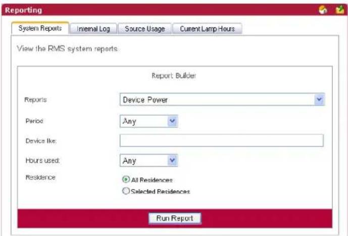
FIG. 115 Power Reports - Device Power
| Power Reports - Device Power | |
| • Period | The time parameter the report is to run within. Click the calendar(s) to select a date; otherwise, type the date in the field provided. • On/After - Selects all instances on or after the designated date. • On - Selects all instances on the designated date. • On/Before - Selects all instances on or before the designated date. • Between - Selects all instances between the designated dates. • Any - Selects all instances. |
| Power Reports - Device Power (Cont.) | |
| Options | Device like- A keyword search for specific device items.Hours used:>= - Selects all instances that are greater than and equal to the number you place in the field.= - Selects all instances that are equal to the number you place in the field.<= - Selects all instances that are less than and equal to the number you place in the field.Between- Selects all instances that are greater than and equal to the number you place in the field but less than and equal to the other number.Any- Selects all instances. |
| Residence | Select either All Residences or Selected Residences. The latter provides a list of rooms and groups available within the RMS system. |
| Run Report | Generates the report. |
Power Reports - Device Power Results
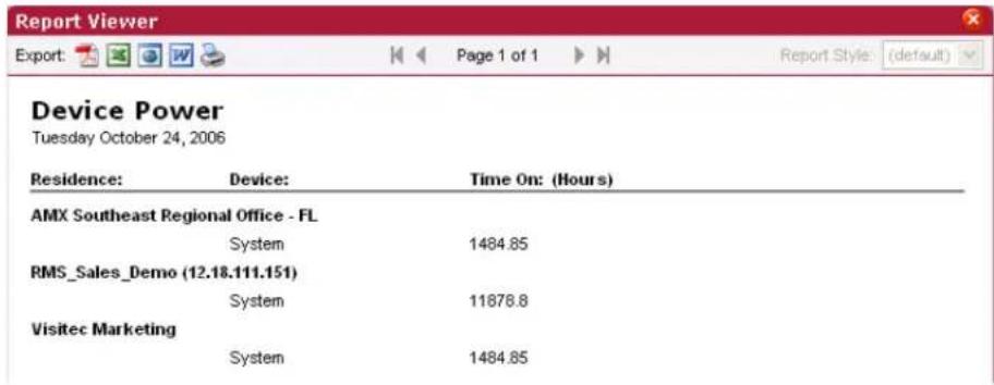
FIG. 116 Power Reports - Device Power Results
| Power Reports - Device Power Results | |
| • Residence The rooms being tracked for usage. | |
| • Device The device in use. | |
| • Time On (Hours) | The amount of time, in hours, the device has been in use. |
Power Reports - System Power (Detailed)
This report provides the times each system was turned on or off between the start and end dates for all rooms included in the report (FIG. 117). This report includes a large quantity of data, it is recommended that you run this report for a single room and/or a short reporting period.
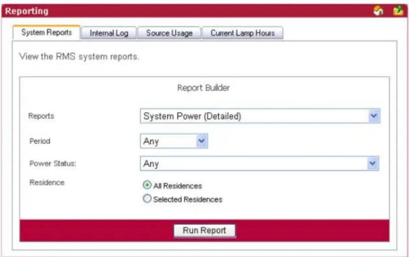
FIG. 117 Power Reports - System Power (Detailed)
| Power Reports - System Power (Detailed) | |
| • Period The time parameter the report is to run within. Click the calendar(s) to select a date; otherwise, type the date in the field provided.• On/After - Selects all instances on or after the designated date.• On - Selects all instances on the designated date.• On/Before - Selects all instances on or before the designated date.• Between - Selects all instances between the designated dates.• Any - Selects all instances. | |
| • Options | • Device like - A keyword search for specific device items.• Power Status - A drop down selection; your choices are On and Off. |
| • Residence | Select either All Residences or Selected Residences. The latter provides a list of rooms and groups available within the RMS system. |
| • Run Report | Generates the report. |
Power Reports - System Power (Detailed) Results
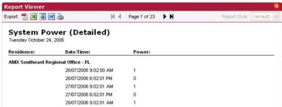
FIG. 118 Power Reports - System Power (Detailed) Results
| Power Reports - System Power (Detailed) Results | |
| • Residence | The rooms being tracked for usage. |
| • Date/Time | The date and time the system power change occurred. |
| • Power The status of the power, on or off. | |
Quality of Service Reports
Quality of Service Reports - System Online
This report provides the count, number of minutes, and quality of service for each NetLinx system that reported Offline between the start and end dates for all rooms included in the report (FIG. 119). This report is based on the "System Online" parameter.
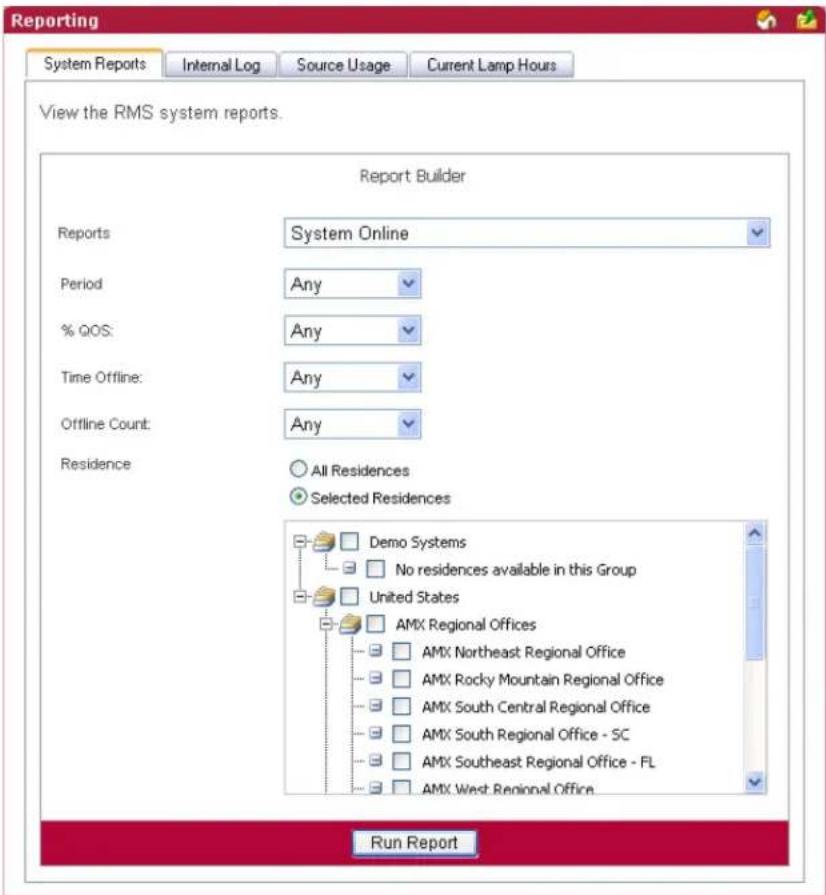
FIG. 119 Quality of Service Reports - System Online
| Quality of Service Reports -System Online | |
| • Period | The time parameter the report is to run within. Click the calendar(s) to select a date; otherwise, type the date in the field provided.• On/After - Selects all instances on or after the designated date.• On - Selects all instances on the designated date.• On/Before - Selects all instances on or before the designated date.• Between - Selects all instances between the designated dates.• Any - Selects all instances. |
| Quality of Service Reports - System Online (Cont.) | |
| Options % QOS (Percentage of Quality of Service):>= - Selects all instances that are greater than and equal to the number you place in the field.= - Selects all instances that are equal to the number you place in the field.<= - Selects all instances that are less than and equal to the number you place in the field.Between - Selects all instances that are greater than and equal to the number you place in the field but less than and equal to the other number.Any - Selects all instances.Time Offline:>= - Selects all times offline that are greater than and equal to the number you place in the field.= - Selects all times offline that are equal to the number you place in the field.<= - Selects all time offline that are less than and equal to the number you place in the field.Between - Selects all times offline that are greater than and equal to the number you place in the field but less than and equal to the other number.Any - Selects all times offline.Offline Count:>= - Selects all time offline counters that are greater than and equal to the number you place in the field.= - Selects all time offline counters that are equal to the number you place in the field.<= - Selects all time offline counters that are less than and equal to the number you place in the field.Between - Selects all time offline counters that are greater than and equal to the number you place in the field but less than and equal to the other number.Any - Selects all time offline counters. | |
| • Residence | Select either All Residences or Selected Residences. The latter provides a list of rooms and groups available within the RMS system. |
| • Run Report Generates the report. | |
Quality of Service Reports - System Online Results
| Residence: | Quality of Service: (%) | Time Offline: (Minutes) | # of Times Offline: |
| AMX Southeast Regional Office - FL | 99.99 % | 8 | 3 |
| RMS_Sales_Demo(12.18.111.151) | 99.99 % | 10 | 3 |
| RMS_Sales_Demo(12.18.111.151) | 99.99 % | 11 | 3 |
FIG. 120 Quality of Service Reports - System Online Results
| Quality of Service Reports - System Online Results | |
| • Residence The rooms being tracked for usage. | |
| • Quality of Service (%) The percentage of quality of service. | |
| • Time Offline (Minutes) The amount of time, in minutes, the system is offline. | |
| • # of Times Offline The number of times the system has reported offline. |
Quality of Service Reports - Device Online
This report provides the count, number of minutes, and quality of service for each NetLinx device that reported Offline between the start and end dates for all rooms included in the report (FIG. 121). This report is based on the Device Online parameter.
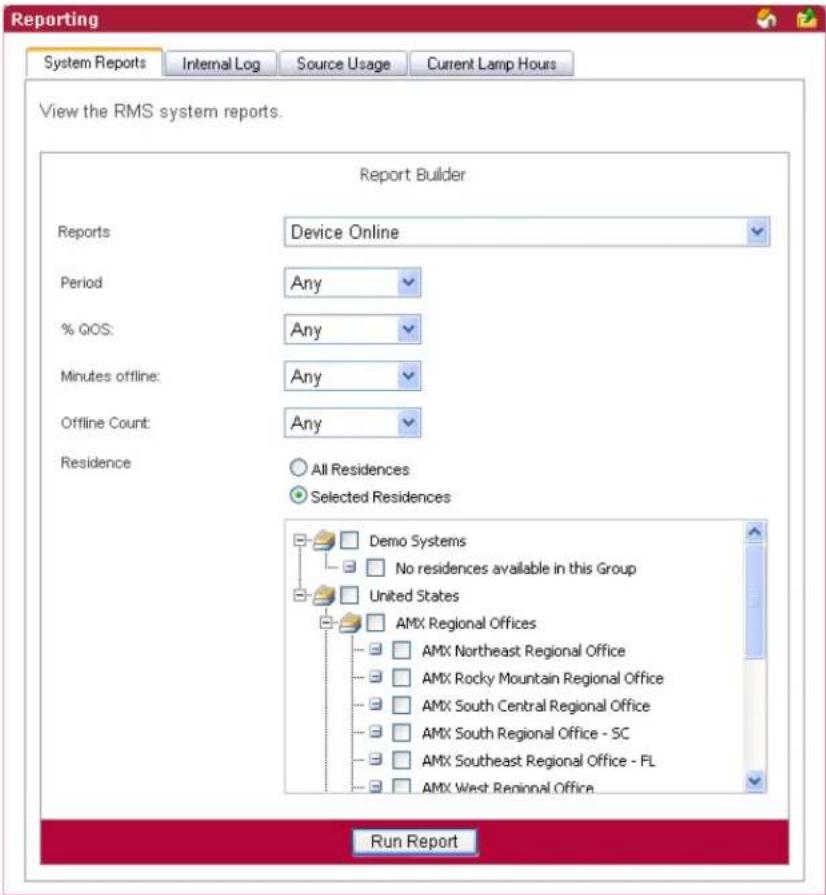
FIG. 121 Quality of Service Reports - Device Online
| Quality of Service Reports - Device Online | |
| • Period | The time parameter the report is to run within. Click the calendar(s) to select a date; otherwise, type the date in the field provided.• On/After - Selects all instances on or after the designated date.• On - Selects all instances on the designated date.• On/Before - Selects all instances on or before the designated date.• Between - Selects all instances between the designated dates.• Any - Selects all instances. |
| Quality of Service Reports - Device Online (Cont.) | |
| Options % QOS (Percentage of Quality of Service):>= - Selects all instances that are greater than and equal to the number you place in the field.= - Selects all instances that are equal to the number you place in the field.<= - Selects all instances that are less than and equal to the number you place in the field.Between - Selects all instances that are greater than and equal to the number you place in the field but less than and equal to the other number.Any - Selects all instances.Minutes Offline:>= - Selects all times offline that are greater than and equal to the number you place in the field.= - Selects all times offline that are equal to the number you place in the field.<= - Selects all time offline that are less than and equal to the number you place in the field.Between - Selects all times offline that are greater than and equal to the number you place in the field but less than and equal to the other number.Any - Selects all times offline.Offline Count:>= - Selects all time offline counters that are greater than and equal to the number you place in the field.= - Selects all time offline counters that are equal to the number you place in the field.<= - Selects all time offline counters that are less than and equal to the number you place in the field.Between - Selects all time offline counters that are greater than and equal to the number you place in the field but less than and equal to the other number.Any - Selects all time offline counters. | |
| • Residence | Select either All Residences or Selected Residences. The latter provides a list of rooms and groups available within the RMS system. |
| • Run Report | Generates the report. |
Quality of Service Reports - Device Online Results
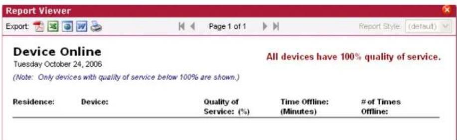
FIG. 122 Quality of Service Reports - Device Online Results
| Quality of Service Reports - Device Online Results | |
| • Residence The rooms being tracked for usage. | |
| • Device The name of the device reporting online. | |
| • Quality of Service (%) The percentage of quality of service. | |
| • Time Offline (Minutes) The amount of time, in minutes, the device is offline. | |
| • # of Times Offline The number of times the device has reported offline. |
Quality of Service Reports - Device Communications
This report provides the count, number of minutes, and quality of service for each NetLinx device that was not able to communicate within the parameters for all rooms included in the report (FIG. 123). This report is based on the Device Communicating parameter.
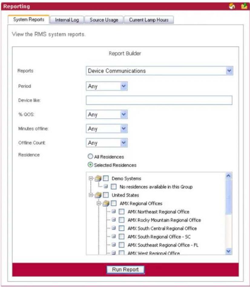
FIG. 123 Quality of Service Reports - Device Communications
| Quality of Service Reports - Device Communications | |
| • Period | The time parameter the report is to run within. Click the calendar(s) to select a date; otherwise, type the date in the field provided.• On/After - Selects all instances on or after the designated date.• On - Selects all instances on the designated date.• On/Before - Selects all instances on or before the designated date.• Between - Selects all instances between the designated dates.• Any - Selects all instances. |
| Quality of Service Reports - Device Communications (Cont.) | |
| Options • Device like - A keyword search for specific device items. | % QOS (Percentage of Quality of Service):>= - Selects all instances that are greater than and equal to the number you place in the field.= - Selects all instances that are equal to the number you place in the field.<= - Selects all instances that are less than and equal to the number you place in the field.Between - Selects all instances that are greater than and equal to the number you place in the field but less than and equal to the other number.Any - Selects all instances.Minutes Offline:>= - Selects all times offline that are greater than and equal to the number you place in the field.= - Selects all times offline that are equal to the number you place in the field.<= - Selects all time offline that are less than and equal to the number you place in the field.Between - Selects all times offline that are greater than and equal to the number you place in the field but less than and equal to the other number.Any - Selects all times offline. |
| • Residence | Select either All Residences or Selected Residences. The latter provides a list of rooms and groups available within the RMS system. |
| • Run Report | Generates the report. |
Quality of Service Reports - Device Communications Results
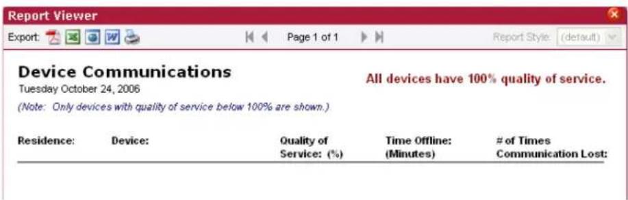
FIG. 124 Quality of Service Reports - Device Communications Results
| Quality of Service Reports - Device Communications Results | |
| • Residence The rooms being tracked for usage. | |
| • Device The device in use. | |
| • Quality of Service (%) The percentage of quality of service. | |
| • Time Offline (Minutes) | The amount of time, in minutes, the device communications are offline. |
| • # of Times Communications Lost | The number of times the communications has reported offline. |
Quality of Service Reports - Device Control Failures
This report provides the count for each device NetLinx was not able to control within the parameters for all rooms included in the report (FIG. 125). This report is based on the Control Failure parameter.
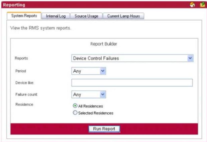
FIG. 125 Quality of Service Reports - Device Control Failures
| Quality of Service Reports - Device Control Failures | |
| • Period | The time parameter the report is to run within. Click the calendar(s) to select a date; otherwise, type the date in the field provided.• On/After - Selects all instances on or after the designated date.• On - Selects all instances on the designated date.• On/Before - Selects all instances on or before the designated date.• Between - Selects all instances between the designated dates.• Any - Selects all instances. |
| • Options • Device like - A keyword search for specific device items.Failure Count:>= - Selects all instances that are greater than and equal to the number you place in the field.= - Selects all instances that are equal to the number you place in the field.<= - Selects all instances that are less than and equal to the number you place in the field.Between - Selects all instances that are greater than and equal to the number you place in the field but less than and equal to the other number.Any - Selects all instances. | |
| • Residence | Select either All Residences or Selected Residences. The latter provides a list of rooms and groups available within the RMS system. |
| • Run Report Generates the report. | |
Quality of Service Reports - Device Control Failures Results
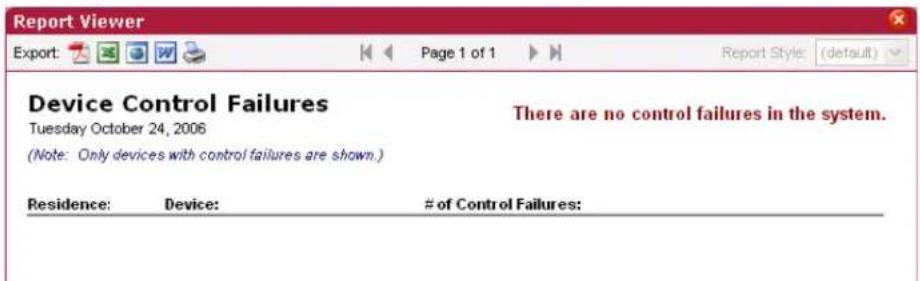
FIG. 126 Quality of Service Reports - Device Control Failures Results
| Quality of Service Reports - Device Control Failures Results | |
| • Residence The rooms being tracked for usage. | |
| • Device The device in use. | |
| • # of Control Failures The number of times a device control failure was detected. |
Scheduler Reports
Scheduler Reports - Help Requests
This report provides a count of all help entered by any user within the parameters for all rooms included in the report (FIG. 127).
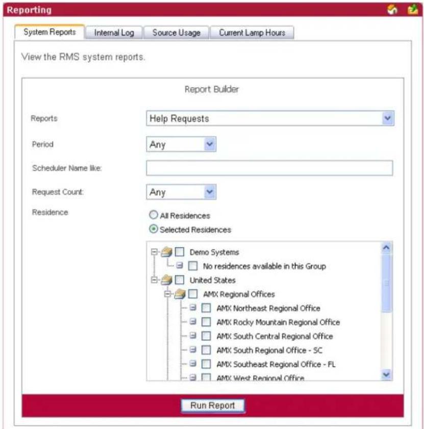
FIG. 127 Scheduler Reports - Help Requests
| Scheduler Reports - Help Requests | |
| • Period | The time parameter the report is to run within. Click the calendar(s) to select a date; otherwise, type the date in the field provided.• On/After - Selects all instances on or after the designated date.• On - Selects all instances on the designated date.• On/Before - Selects all instances on or before the designated date.• Between - Selects all instances between the designated dates.• Any - Selects all instances. |
| • Options • Organizer Name like - A keyword search for specific organizers.Request Count:• >= - Selects all instances that are greater than and equal to the number you place in the field.• = - Selects all instances that are equal to the number you place in the field.• <= - Selects all instances that are less than and equal to the number you place in the field.• Between - Selects all instances that are greater than and equal to the number you place in the field but less than and equal to the other number.• Any - Selects all instances. | |
| • Residence | Select either All Residences or Selected Residences. The latter provides a list of rooms and groups available within the RMS system. |
| • Run Report Generates the report. | |
Scheduler Reports - Help Requests Results
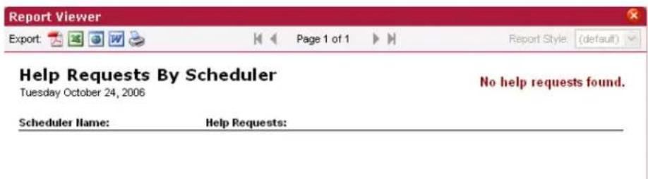
FIG. 128 Scheduler Reports - Help Requests Results
| Scheduler Reports - Help Requests Results | |
| • Scheduler Name | The name of the organizer placing the help request. |
| • Help Requests The number of help requests placed by the organizer. | |
Scheduler Reports - Help Requests (Detailed)
This report provides a list of all help entered by any user within the parameters for all rooms included in the report (FIG. 129).
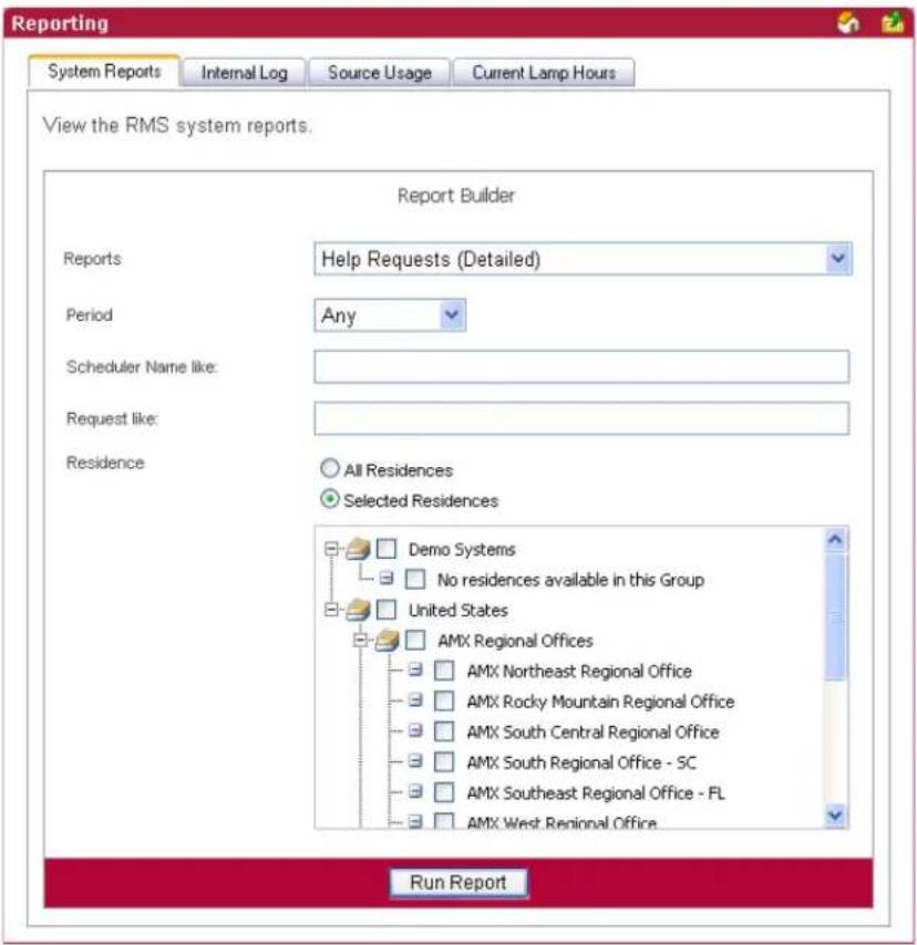
FIG. 129 Scheduler Reports - Help Requests (Detailed)
| Scheduler Reports - Help Requests (Detailed) | |
| • Period The time parameter the report is to run within. Click the calendar(s) to select a date; otherwise, type the date in the field provided.• On/After - Selects all instances on or after the designated date.• On - Selects all instances on the designated date.• On/Before - Selects all instances on or before the designated date.• Between - Selects all instances between the designated dates.• Any - Selects all instances. | |
| • Options • Scheduler Name like - A keyword search for specific organizers.• Request like - A keyword search for specific help requests. | |
| • Residence | Select either All Residences or Selected Residences. The latter provides a list of rooms and groups available within the RMS system. |
| • Run Report Generates the report. | |
Scheduler Reports - Help Requests (Detailed) Results
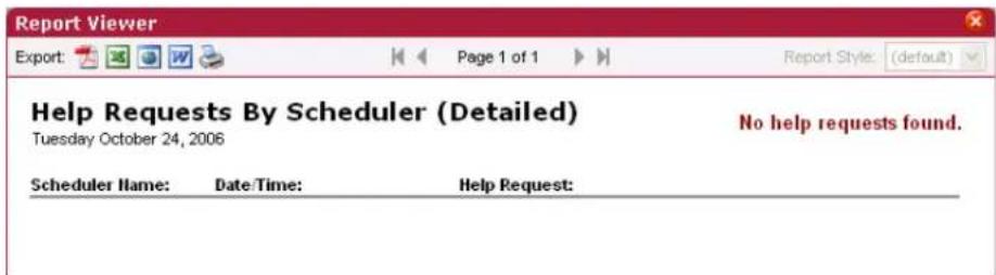
FIG. 130 Scheduler Reports - Help Requests (Detailed) Results
| Scheduler Reports - Help Requests (Detailed) Results | |
| • Scheduler Name | The name of the organizer placing the help request. |
| • Date/Time The date and time the help request occurred. | |
| • Help Request The text of each particular help request. | |
Scheduler Reports - Room Usage
This report provides the number of hours a room has been scheduled via the RMS application's scheduling feature for all rooms within the parameters for all rooms included in the report (FIG. 130). If the scheduling features of the RMS application are not being used, this report will not contain any useful data.
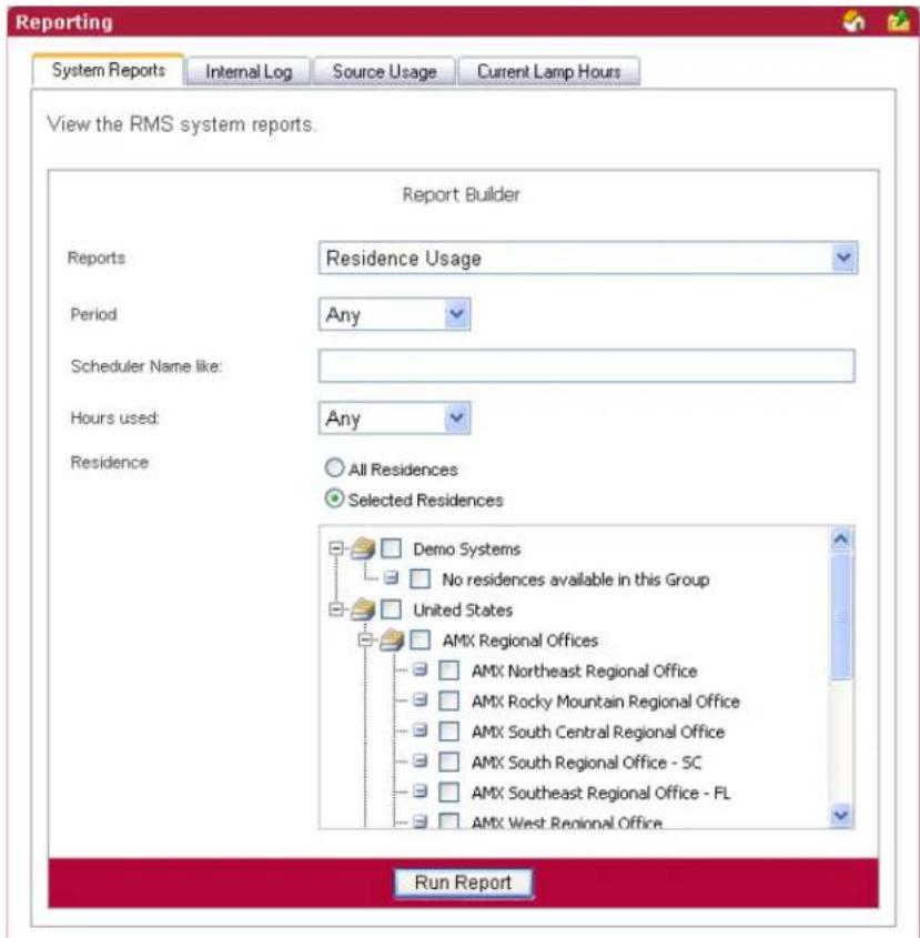
FIG. 131 Scheduler Reports - Residence Usage
| Scheduler Reports - Room Usage | |
| • Period | The time parameter the report is to run within. Click the calendar(s) to select a date; otherwise, type the date in the field provided.• On/After - Selects all instances on or after the designated date.• On - Selects all instances on the designated date.• On/Before - Selects all instances on or before the designated date.• Between - Selects all instances between the designated dates.• Any - Selects all instances. |
| • Options • Organizer Name like - A keyword search for specific organizers.Hours Used:• >= - Selects all instances that are greater than and equal to the number you place in the field.• = - Selects all instances that are equal to the number you place in the field.• <= - Selects all instances that are less than and equal to the number you place in the field.• Between - Selects all instances that are greater than and equal to the number you place in the field but less than and equal to the other number.• Any - Selects all instances. | |
| • Residence | Select either All Residences or Selected Residences. The latter provides a list of rooms and groups available within the RMS system. |
| • Run Report | Generates the report. |
Scheduler Reports - Room Usage Results
This report provides the number of minutes a source has been selected, i.e., viewed, for all sources in all rooms within the parameters for all rooms included in the report (FIG. 132).
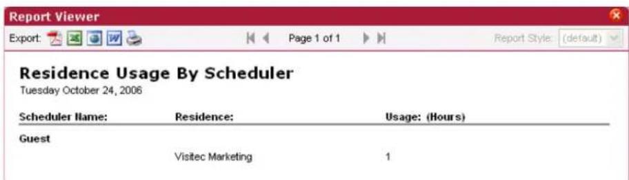
FIG. 132 Scheduler Reports - Residence Usage Results
| Scheduler Reports - Room Usage Results | |
| • Scheduler Name | The name of the organizer placing the help request. |
| • Residence The rooms being tracked for usage. | |
| • Usage The amount of time, in hours, the organizer has used that room. | |
Scheduler Reports - Source Usage
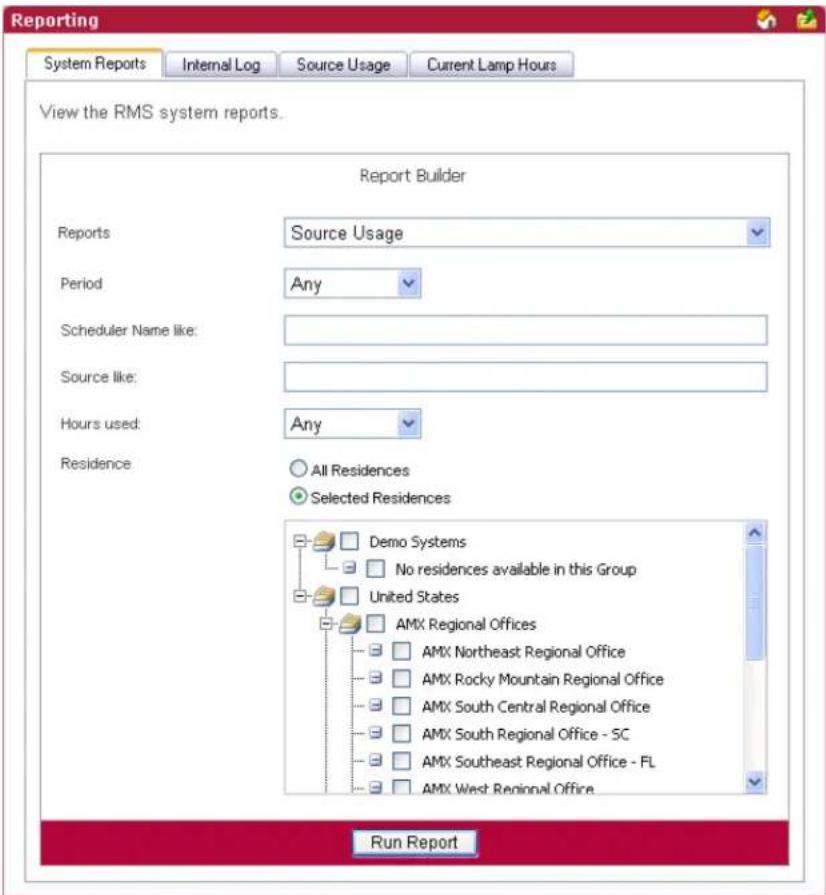
FIG. 133 Scheduler Reports - Source Usage
| Scheduler Reports - Source Usage | |
| • Period | The time parameter the report is to run within. Click the calendar(s) to select a date; otherwise, type the date in the field provided.• On/After - Selects all instances on or after the designated date.• On - Selects all instances on the designated date.• On/Before - Selects all instances on or before the designated date.• Between - Selects all instances between the designated dates.• Any - Selects all instances. |
| • Options • Organizer Name like - A keyword search for specific organizers.• Source like - A keyword search for a specific source.Hours Used:• >= - Selects all instances that are greater than and equal to the number you place in the field.• = - Selects all instances that are equal to the number you place in the field.• <= - Selects all instances that are less than and equal to the number you place in the field.• Between - Selects all instances that are greater than and equal to the number you place in the field but less than and equal to the other number.• Any - Selects all instances. | |
| Scheduler Reports - Source Usage (Cont.) | |
| • Residence | Select either All Residences or Selected Residences. The latter provides a list of rooms and groups available within the RMS system. |
| • Run Report | Generates the report. |
Scheduler Reports - Source Usage Results
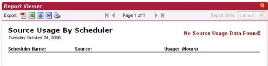
FIG. 134 Scheduler Reports - Source Usage Results
| Scheduler Reports - Source Usage Results | |
| • Scheduler Name | The name of the organizer placing the help request. |
| • Source The name | of the source used by the organizer. |
| • Usage (Hours) | The amount of time, in hours, the organizer has used that source. |
Running a System Report
- Select Reporting > System Reports in the menu on the left side of the RMS application. The System Reports page opens.
-
Select one of the following Reports from the drop down menu:
-
Help Requests (see the System Reports - Help Requests section on page 104 for more information.)
- Help Requests (Detailed) (see the System Reports - Help Requests (Detailed) section on page 105 for more information.)
- Residence Usage (see the System Reports - Residence Usage section on page 107 for more information.)
- Source Usage (see the System Reports - Source Usage section on page 108 for more information.)
- Cumulative Lamp Hours (see the System Reports - Cumulative Lamp Hours section on page 110 for more information.)
- Transport Run Time (see the System Reports - Transport Run Time section on page 112 for more information.)
- Current Source Usage (see the System Reports - Current Source Usage section on page 114 for more information.)
- Current Lamp Hour (see the System Reports - Current Lamp Hour section on page 116 for more information.)
● System Power (see the Power Reports - System Power section on page 118 for more information.)
● Device Power (see the Power Reports - Device Power section on page 119 for more information.) - System Power (see the Power Reports - System Power section on page 118 for more information.)
- System Power (Detailed) (see the Power Reports - System Power (Detailed) section on page 121 for more information.)
-
System Online (see the Quality of Service Reports - System Online section on page 122 for more information.)
● Device Online (see the Quality of Service Reports - Device Online section on page 124 for more information.)
● Device Communications (see the Quality of Service Reports - Device Communications section on page 126 for more information.) -
Device Control Failures (see the Quality of Service Reports - Device Control Failures section on page 128 for more information.)
- Help Requests (see the Scheduler Reports - Help Requests section on page 129 for more information.)
- Help Requests (Detailed) (see the Scheduler Reports - Help Requests (Detailed) section on page 131 for more information.)
- Residence Usage (see the Scheduler Reports - Room Usage section on page 132 for more information.)
- Source Usage (see the Scheduler Reports - Source Usage section on page 134 for more information.)
- Device Activity (see the Tracking Reports - Device Activity section on page 137 for more information.)
- Device Activity (Detailed) (see the Tracking Reports - Device Activity (Detailed) section on page 138 for more information.)
- Room Activity (see the Tracking Reports - Room Activity section on page 140 for more information.)
- Device Location (see the Tracking Reports - Device Location section on page 141 for more information.)
-
Device Battery Levels (see the Tracking Reports - Device Battery Levels section on page 143 for more information.)
-
Enter the parameters for the report.
-
Click Run Report.
Tracking Reports
Tracking Reports - Device Activity
This report displays a device-centric view of the device's RFID tag activity over a user-defined period of time (FIG. 135).
● The report is grouped by device name.
- Only rooms configured for RFID appear in this report.
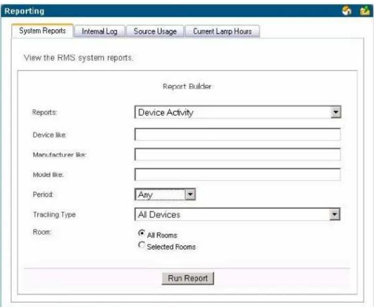
FIG. 135 Tracking Reports - Device Activity
| Tracking Reports - Device Activity | |
| Options•Device like - A keyword search for specific devices. | Manufacturer like - A keyword search for a specific device manufacturer.Model like - A keyword search for a specific device model.Period:>= - Selects all instances that are greater than and equal to the date you enter in the first field.= - Selects all instances that are equal to the date you enter in the first field.<= - Selects all instances that are less than and equal to the date you enter in the first field.Between - Selects all instances that are greater than and equal to the date you enter in the first field but less than and equal to the date you enter in the second field.Any - Selects all instances.Tracking Type - Enables you to limit the search results to only devices configured asPortable, devices configured asFixed Locationdevices, orAll Devices. |
| Room | Select eitherAll RoomsorSelected Rooms.The latter provides a list of rooms and groups available within the RMS system. |
| Run ReportGenerates the report. | |
Tracking Reports - Device Activity Results
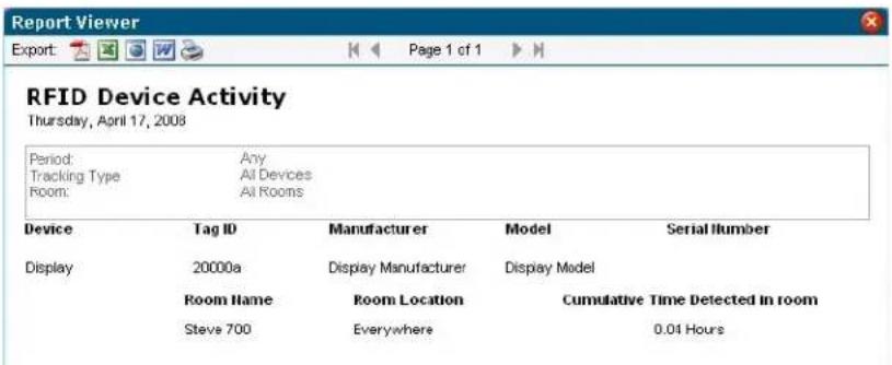
FIG. 136 Tracking Reports - Device Activity Results
| Tracking Reports - Device Activity Results | |
| • Device The name of the device. | |
| • Tag ID The device's RFID tag ID. | |
| • Manufacturer The name of the device manufacturer. | |
| • Model The name of the device model. | |
| • Serial Number The serial number of the device. | |
| • Room Name The name of the room in which the device resides. | |
| • Room Location The location of the room. | |
| • Cumulative Time Detected in Room | The amount of time, in hours, the RFID reader has detected that the device has been in the room. |
Tracking Reports - Device Activity (Detailed)
This report displays a device-centric view of the device's RFID tag activity over a user-defined period of time.
● The report is grouped by device name (FIG. 137).
- Only rooms configured for RFID appear in this report.
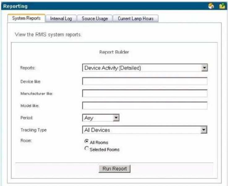
FIG. 137 Tracking Reports - Device Activity (Detailed)
| Tracking Reports - Device Activity (Detailed) | |
| Options • Device like - A keyword search for specific devices. | Manufacturer like - A keyword search for a specific device manufacturer.Model like - A keyword search for a specific device model.Period:>= - Selects all instances that are greater than and equal to the date you enter in the first field.= - Selects all instances that are equal to the date you enter in the first field.<= - Selects all instances that are less than and equal to the date you enter in the first field.Between - Selects all instances that are greater than and equal to the date you enter in the first field but less than and equal to the date you enter in the second field.Any - Selects all instances.Tracking Type - Enables you to limit the search results to only devices configured as Portable, devices configured as Fixed Location devices, or All Devices. |
| Room | Select either All Rooms or Selected Rooms. The latter provides a list of rooms and groups available within the RMS system. |
| Run Report Generates the report. | |
Tracking Reports - Device Activity (Detailed) Results
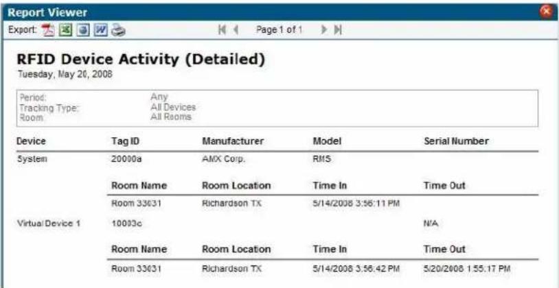
FIG. 138 Tracking Reports - Device Activity (Detailed) Results
| Tracking Reports - Device Activity (Detailed) Results | |
| • Device The name of the device. | |
| • Tag ID The device's RFID tag ID. | |
| • Manufacturer The name of the device manufacturer. | |
| • Model The name of the device model. | |
| • Serial Number The serial number of the device. | |
| • Room Name The name of the room in which the RFID reader detects the device. | |
| • Room Location The room location in which the RFID reader detects the device. | |
| • Time In The timestamp for when the RFID reader last detected the device being online. | |
| • Time Out The timestamp for when the RFID reader last detected the device being offline. |
Tracking Reports - Room Activity
This report displays a room-centric view of the device's RFID tag activity over a user-defined period of time (FIG. 139). The report is grouped by room name. Only rooms configured for RFID appear in this report.
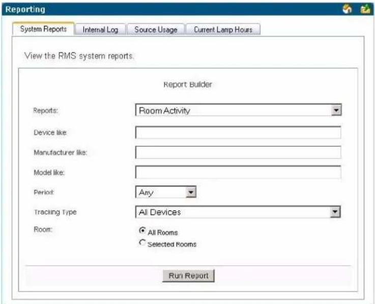
FIG. 139 Tracking Reports - Room Activity
| Tracking Reports - Room Activity | |
| Options·Device like - A keyword search for specific devices. | Manufacturer like - A keyword search for a specific device manufacturer.Model like - A keyword search for a specific device model.Period:>= - Selects all instances that are greater than and equal to the date you enter in the first field.= - Selects all instances that are equal to the date you enter in the first field.<= - Selects all instances that are less than and equal to the date you enter in the first field.Between - Selects all instances that are greater than and equal to the date you enter in the first field but less than and equal to the date you enter in the second field.Any - Selects all instances.Tracking Type - Enables you to limit the search results to only devices configured as Portable, devices configured as Fixed Location devices, or All Devices. |
| Room | Select either All Rooms or Selected Rooms. The latter provides a list of rooms and groups available within the RMS system. |
| Run Report | Generates the report. |
Tracking Reports - Room Activity Results
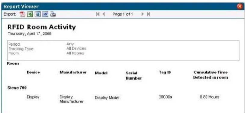
FIG. 140 Tracking Reports - Room Activity Results
| Tracking Reports - Room Activity Results | |
| • Device The name of | the device. |
| • Room The name of | the room in which the device resides. |
| • Manufacturer The name of | the device manufacturer. |
| • Model The name of | the device model. |
| • Serial Number The serial number of the device. | |
| • Tag ID The device's | RFID tag ID. |
| • Cumulative Time Detected in Room | The amount of time, in hours, the RFID reader has detected that the device has been in the room. |
Tracking Reports - Device Location
This report displays a room-centric view of the device's RFID tag's current location (FIG. 141). If the RFID tag is not currently online, the report gives the last known location of the RFID tag. The report is grouped by device name. Only devices configured for RFID appear in this report.
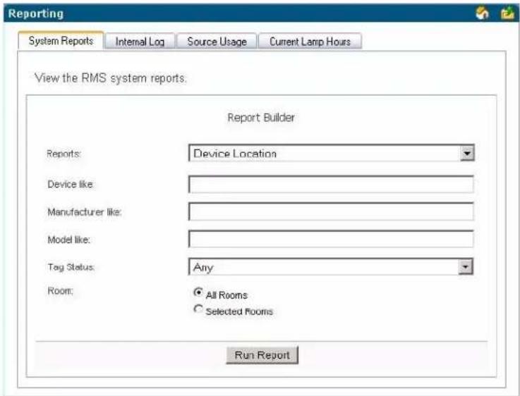
FIG. 141 Tracking Reports - Device Location
| Tracking Reports - Device Location | |
| Options • Name like - A keyword search for name of the device. | |
| • Manufacturer like - A keyword search for a specific device manufacturer.• Model like - A keyword search for a specific device model.• Tag Status - Enables you to limit the search results to only include devices where the RFID tag is either Online or Offline. You can also select Any to include all device tag status states. | |
| Room | Select either All Rooms or Selected Rooms. The latter provides a list of rooms and groups available within the RMS system. |
| Run Report | Generates the report. |
Tracking Reports - Device Location Results
| RFID Device Location Tuesday, May 20, 2006 | ||||||||
| Tag Status Room: Any All Rooms | ||||||||
| Device | Room Name | Manufacturer | Model | Serial Number | Tag ID | Detected Location | Last Timestamp | Tag Status |
| System | Room 33031 | AMX Corp | RMS | 20000a | Room 33031 | 5/15/2008 1:56:25 PM | Online | |
| Virtual Device 1 | Room 33031 | N/A | 10003c | Room 33031 | 5/20/2008 1:55:17 PM | Online | ||
FIG. 142 Tracking Reports - Device Location Results
| Tracking Reports - Device Location Results | |
| • Device The name of the device. | |
| • Room Name The name of the room in which the device resides. | |
| • Manufacturer The name of the device manufacturer. | |
| • Model The name of the device model. | |
| • Serial Number The serial number of the device. | |
| • Tag ID The device's RFID tag ID. | |
| • Detected Location The room name of the last known location of the device. | |
| • Last Timestamp The timestamp for when the RFID reader detected the device being online. | |
| • Tag Status The current status of the RFID tag. The status is either Online or Offline. |
Tracking Reports - Device Battery Levels
This report displays a room-centric view of the device's RFID tag and their current battery levels (FIG. 143). The purpose of this report is to provide a quick report for RFID tag's battery level. The report is grouped by device name. Only devices configured for RFID appear in this report.
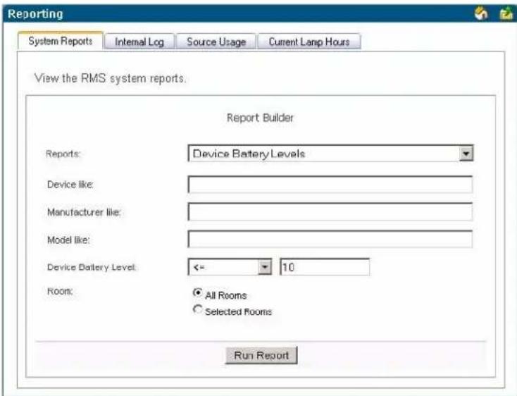
FIG. 143 Tracking Reports - Device Battery Levels
| Tracking Reports - Device Battery Levels | |
| Options • Name like - A keyword search for name of the device. | • Manufacturer like - A keyword search for a specific device manufacturer.• Model like - A keyword search for a specific device model.RFID Tag Battery Level:• >= - Selects all instances that are greater than and equal to the value you enter in the first field.• = - Selects all instances that are equal to the value you enter in the first field.• <= - Selects all instances that are less than and equal to the value you enter in the first field.• Between - Selects all instances that are greater than and equal to the value you enter in the first field but less than and equal to the value you enter in the second field.• Any - Selects all instances.The default setting for this search parameter is “Battery Power Level Less Than 10%”. |
| Room | Select either All Rooms or Selected Rooms. The latter provides a list of rooms and groups available within the RMS system. |
| Run Report | Generates the report. |
Tracking Reports - Device Battery Levels Results
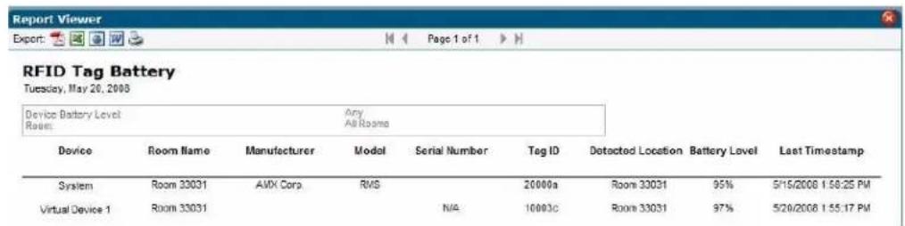
FIG. 144 Tracking Reports - Device Battery Levels Results
| Tracking Reports - Device Battery Levels Results | |
| • Device The name of the device. | |
| • Room Name The name of the room in which the device resides. | |
| • Manufacturer The name of the device manufacturer. | |
| • Model The name of the device model. | |
| • Serial Number The serial number of the device. | |
| • Tag ID The device's RFID tag ID. | |
| • Detected Room | The room name of the last detected location of the device. This information only appears in the device's RFID tag is currently offline. |
| • Battery Level The percentage of remaining battery power for the RFID tag. | |
| • Last Timestamp The timestamp for when the RFID reader detected the device being online. | |
Administrative Reports
Administrative Reports - Device Inventory
This report provides a detailed listing of all devices (excluding source usage devices) in the RMS system (FIG. 145). The report is grouped by room name.
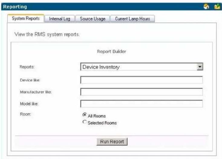
FIG. 145 Device Inventory
| Administrative Reports - Device Inventory | |
| • Options • Device Name like - A keyword search for name of the device. | • Device Manufacturer like - A keyword search for a specific device manufacturer.• Device Model like - A keyword search for a specific device model. |
| • Room | Select eitherAll RoomsorSelected Rooms. The latter provides a list of rooms and groups available within the RMS system. |
| • Run Report Generates the report. | |
Administrative Reports - Device Inventory Results
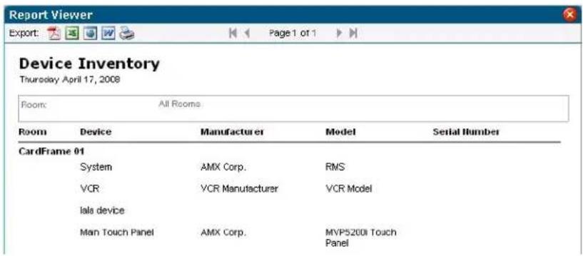
FIG. 146 Administrative Reports - Device Inventory Results
| Administrative Reports - Device Inventory Results | |
| • Device Name The name of the device. | |
| • Device Manufacturer The name of the device manufacturer. | |
| • Device Model The name of the device model. |
Administrative Reports - Device Inventory Results (Cont.)
• Device Serial Number The serial number of the device.
• Device RFID Tag ID The device's RFID tag ID.
Administrative Reports - Control System Inventory
This report provides a detailed listing of all the control masters defined in the RMS system (FIG. 147).
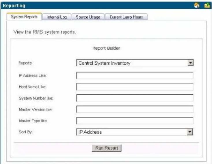
FIG. 147 Administrative Reports - Control System Inventory
Administrative Reports - Control System Inventory
| Options • Master IP Address like - A search for the IP address of the control system.Master Hostname like - A search for the hostname of the control system.Master System Number like - A search for the system number of the control system.Master Firmware Version like - A search for the firmware version of the control system.Master Type like - A search for the type of control system. | |
| Sort by | You can sort the report by any of the available fields by selecting the corresponding option.Choose from Host Name, IP Address, Master Type, Master Version, MAC Address, RMS SDK Version, and Serial Number. |
| Run Report | Generates the report. |
Administrative Reports - Control System Inventory Results
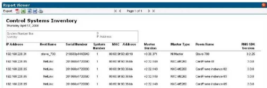
FIG. 148 Administrative Reports - Control System Inventory Results
| Administrative Reports - Control System Inventory Results | |
| • Master Serial Number The serial number of the control system. | |
| • Master IP Address The IP address of the control system. | |
| • Master Hostname The hostname of the control system. | |
| • Master MAC Address The MAC address of the control system. | |
| • Master System Number The system number of the control system. | |
| • Master Firmware Version The firmware version of the control system. | |
| • Master Type The type of control system. | |
| • Room Name The room in which the control system is located. | |
| • RMS SDK Version The RMS SDK version of the control system. |
Administrative Reports - System Users
This report provides a detailed listing of all users defined in the RMS system (FIG. 149).
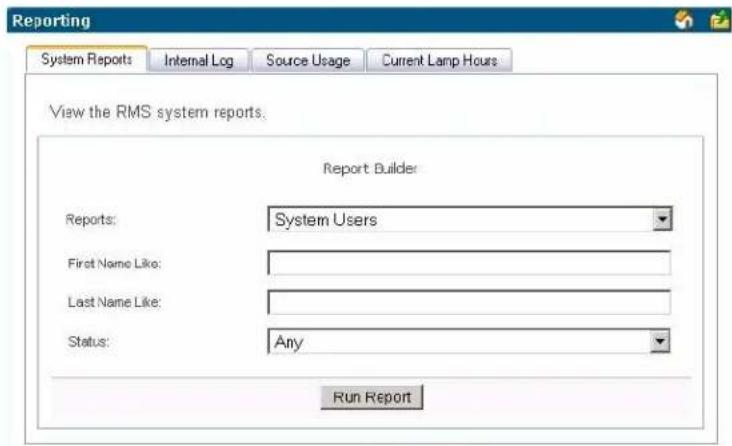
FIG. 149 Administrative Reports - System Users
| Administrative Reports - System Users | |
| • Options First | Name Like - A keyword search for the first name of the user. Last Name Like - A keyword search for the last name of the user. Status - A search for the status of the user. You can choose from Enabled, Disabled, or Any. |
| • Run Report | Generates the report. |
Administrative Reports - System Users Results
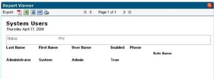
FIG. 150 Administrative Reports - System Users Results
| Administrative Reports - System Users Results | |
| • Last Name The last name of the user. | |
| • First Name The first name of the user. | |
| • User Name The user name of the user. | |
| • Status The current status of the account. This can be either Enabled or Disabled. | |
| • Phone The phone number of the user. | |
| • Role Name A listing of the user's permissions. A user can be assigned to multiple roles. |
Internal Log Report Page
The Internal Log displays parameter changes that reached their thresholds for devices that are configured to report to the Internal Log. The Internal Log is a historical record of all faults on the RMS application system.
| Internal Log Report | |
| • Status Type The type of notification logged. | |
| • Server Time The time on the server the notification was created. | |
| • Room The friendly name of the room where the notification originated. | |
| • Device The device generating the notification. | |
| • Parameter The parameter threshold that necessitated the notification. | |
| • Log Message | An abridged version of the message notification logged. |
| • Options | View - Launches the Internal Log Entry Page section on page 149.Delete - Deletes the selected log entry. |
This table can be sorted by Server Time, Room Name, Device Name, Parameter Name, and Status Type.
You can manage notes for a particular item on the log message screen. The RMS application automatically includes the name and date the note was added.
The Internal Log can be exported and saved on the server in a Comma Separated Value (CSV) formatted text file. This file can then be imported and formatted using other tools, such as Microsoft Excel®. The exported log files currently on a server are displayed on the Internal Log Settings page.
See Also...
● Management - Internal Log Page section on page 95.
- Configure Internal Log Page section on page 154
Internal Log Entry Page
The Internal Log Entry page provides detailed information for each log entry on the RMS server.
| Internal Log Entry | |
| • Status Type The type of notification logged. | |
| • Server Time The time on the server the notification was created. | |
| • Room The friendly name of the room where the notification originated. | |
| • Device The device generating the notification. | |
| • Parameter The parameter threshold that necessitated the notification. | |
| • Description A brief description of the notification. | |
| • Add Note: Username: The user currently logged into this RMS session.Description: Text field for the user to add information for the notification. |
Viewing Log Entries
- Select Reporting > Internal Log in the menu on the left side of the RMS application. The Internal Log Report page opens.
- Select your log entry from the list and click View. The Internal Log Entry page opens.
Adding Notes To Log Entries
- Select Reporting > Internal Log in the menu on the left side of the RMS application. The Internal Log Report page opens.
- Select your log entry from the list and click View. The Internal Log Entry page opens.
- The Username field is populated based on who is logged into RMS. Type your note in the field Description.
- Click Save Note, and repeat as necessary.
- Click Done.
Deleting Log Entries
- Select Reporting > Internal Log in the menu on the left side of the RMS application. The Internal Log Report page opens.
- Select your log entry from the list and click Delete.
Source Usage Page
Display current source usage for all rooms (FIG. 151). Rooms are displayed in a tree view based on groups. Expand all to see all rooms, Collapse all to collapse all groups.
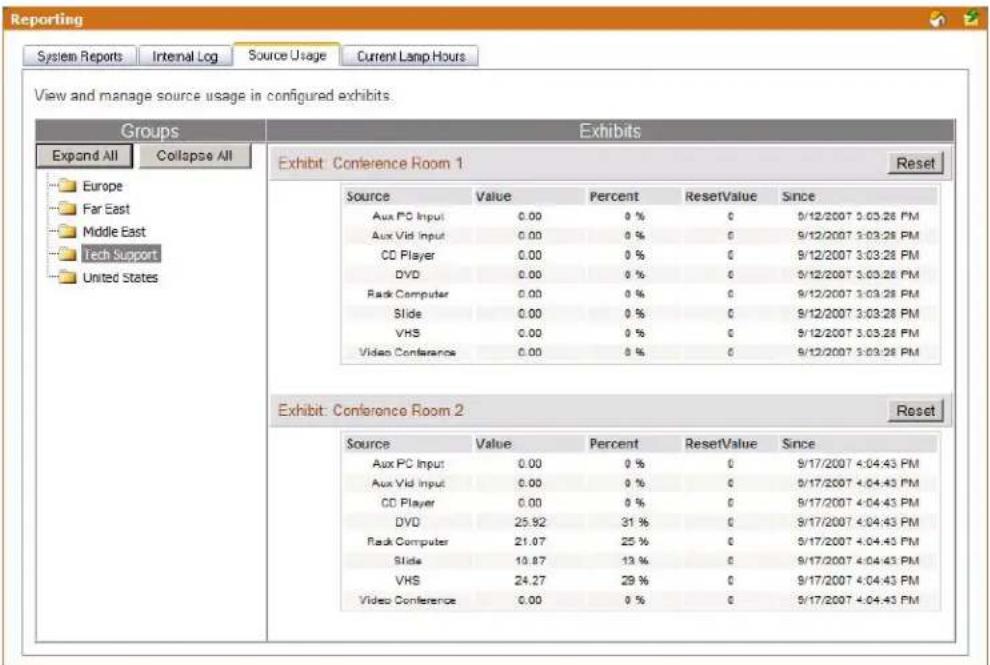
FIG. 151 Source Usage Page
For each source:
| Source Usage | |
| • Source Name of source. | |
| • Usage Usage, in hours, of the source since date/time listed in Since column | |
| • Percent | % of total system usage this represents based on systems power since the date/time in the Since column. |
| • ResetVal | The number of times the source usage has been reset. |
| • Since Date/Time this value was last reset. | |
The Reset button resets the room's source usage.
Viewing Source Usage Reports
- Select Reporting > Source Usage in the menu on the left side of the RMS application. The Source Usage page opens.
- Locate the room for which you want a source usage report; double click groups to expand.
Lamp Hours Report Page
Display current lamp hours for all rooms (FIG. 152). Rooms are displayed in a tree view based on groups. Expand all to see all rooms, or collapse all to collapse all groups. Show triggered, displays lamps that should be replaced within the next two weeks.
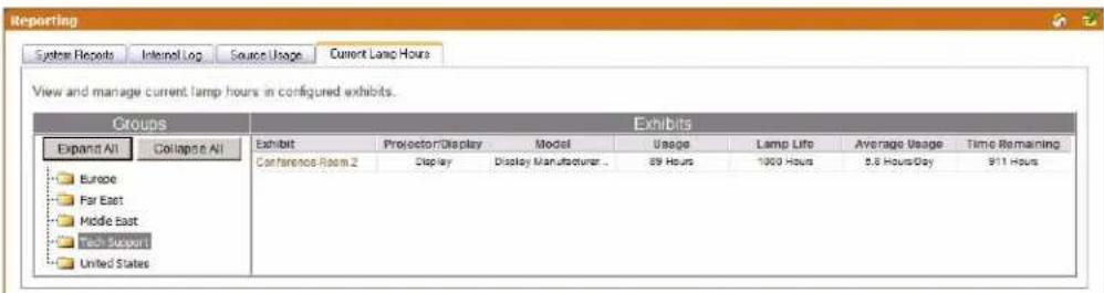
FIG. 152 Lamp Hours Report Page
| Lamp Hours Report | |
| • Room The friendly | name for the room to which the monitored device is associated. |
| • Projector/Display | Name of the projector. |
| • Model Manufacturer | and Model of projector. |
| • Usage Number of | hours on the lamp. |
| • Lamp Life | Expected lamp life set in the RMS application. This is the threshold of the Lamp Hours parameter. |
| • Average Use Average | use in Hours/Day based on historical data in the RMS application. |
| • Time Remaining | Estimated time remaining in days on the lamp based on the expected lamp life and average usage per day.If the lamp is past the established threshold, it displaysReplace Lampin red.If there are 14 days or less left on the lamp, it is displayed in orange.If there are 7 or less days left on the lamp, it is displayed in red. |
Viewing Lamp Hours Reports
- Select Reporting > Lamp Hours in the menu on the left side of the RMS application. The Lamp Hours Report page opens.
- Locate the room for which you want a lamp hour report, and double-click groups to expand.
Reporting Page
Configuration Page
Appointment Settings Page
These settings allow you to set the master appointment modification password and the number of days to retain appointments (FIG. 153).
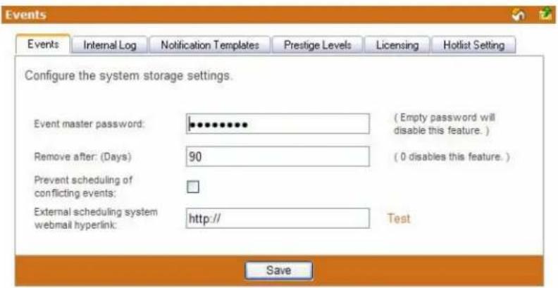
FIG. 153 Appointment Settings Page
| Appointment Settings | |
| Appointment Master Password | A password used to help users who forget individual appointment modification passwords.If a user enters a password for an appointment and then forgets it, this password can be entered and used to clear the appointment password.If this password is left blank, there is no master password for modifying appointments. The default password is 1988. |
| Remove After (Days) | This is the number of days appointments are held in the RMS application system.The default value of 90 days allow users to browse past appointment while minimizing storage requirements.To disable deleting of past appointments, set this value to 0. |
| Prevent scheduling of conflicting appointments | When checked, the RMS application will not permit the scheduling of more than one appointment at the same time. |
| External scheduling system webmail hyperlink | If the RMS application is configured using an external scheduling source, selecting Add Appointment redirects you to the webmail interface defined in this field. |
Configuring The System Storage Settings
-
Select Configuration > Appointments in the menu on the left side of the RMS application. The Appointment Settings page opens.
-
Type to set the Appointment master password. Leaving this field blank disables this feature.
-
Type the number of days RMS is to retain the appointment in the field Remove after: (Days). The value of 0 disables this feature.
-
Enable Prevent scheduling of conflicting appointments by placing a check in the box. If this feature is disabled, it is possible to schedule multiple appointments for the same room at the same time.
-
If the RMS application is configured using an external scheduling source, selecting Add Appointment redirects you to the webmail interface defined in this field. Click Test to confirm the URL works.
-
Click Save to save.
Setting the Appointment Master Password
- Select Configuration > Appointments in the menu on the left side of the RMS application. The Appointment Settings page opens.
- Type to set the Appointment master password. Leaving this field blank disables this feature.
- Click Save to save.
Configure Internal Log Page
The size of the Internal Log is automatically managed by the two Internal Log settings, keeping only messages newer than a given date or by fixing the maximum number of log entries (FIG. 154). Additionally, the Internal Log Settings screen offers an option to purge the entries.
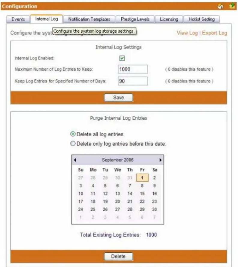
FIG. 154 Internal Log Settings
| Internal Log | |
| • Internal Log Enabled: When | checked the RMS server creates and tracks the internal log. |
| • Maximum Number of Log Entries to Keep: | This value sets the maximum number of messages contained in the Internal Log.The default value of 500 allows administrators to browse past log messages and generate historical report while keeping storage requirements low.If you would rather based the Internal Log size on dates of messages, set this value to 0. |
| Internal Log (Cont.) | |
| ·Keep Log Entries for Specified Number of Days: | This is the number of days log messages will be held in the RMS application system.The default value of 90 days allows administrators to browse past log messages and generate historical report while keeping storage requirements low.If you would rather based the internal log size on number of messages, set this value to 0. |
| ·Purge Internal Log Entries Delete all log entries | This selection deletes all stored internal log entries from the RMS server. |
| Delete only log entries before this date: | Use the calendar to select the start date of the purge. |
| ·Total Existing Log Entries: | The number of internal log entries currently residing on the RMS server. |
See Also...
- Internal Log Report Page section on page 148
● Management - Internal Log Page section on page 95
Configuring the Internal Log
- Select Configuration > Internal Log in the menu on the left side of the RMS application. The Configure Internal Log page opens.
- Place a check in the box Internal Log Enabled to enable the internal log.
- Type the maximum number of logs the RMS server is to keep in the field provided (Maximum Number of Log Entries to Keep). The value 0 disables this feature.
- Type the maximum number of days the RMS server is to keep in the field provided (Keep Log Entries for Specified Number of Days). The value 0 disables this feature.
- Click Save to save.
Enabling/Disabling Internal Log
- Select Configuration > Internal Log in the menu on the left side of the RMS application. The Configure Internal Log page opens.
- Place a check in the box Internal Log Enabled to enable the internal log. Remove the check to disable.
- Click Save to save.
Purging the Internal Log
- Select Configuration > Internal Log in the menu on the left side of the RMS application. The Configure Internal Log page opens.
- If you select Delete all log entries no further information is needed and you can click Delete.
- If you select Delete only log entries before this date:, select a date from the calendar below.
- Click Delete to delete.
Configure Notification Template Page
Templates are used by the RMS application to format emails, pager messages and log messages (FIG. 155). Each template provides the RMS application with a block of text for use in HTML emails, Plan Text emails, Pager messages and log messages.
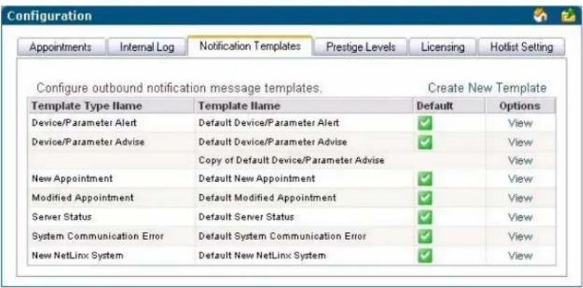
FIG. 155 Configure Notification Template Page
| Configure Notification Template | |
| • TypeName | There are seven different types of templates: • Device Parameter Advise • Device Parameter Alert • Modified Appointment • New Appointment • New NetLinx System • Server Status • System Communication Error |
| • Name A friendly name for the notification. | |
| • View Opens | the notification's settings page. |
See Also...
- Create New Template Page section on page 157
Create New Template Page
The RMS application comes with a default template for each template type. You can create additional template types to override the text used for notification via the options in the Create New Template page (FIG. 156). For any template type, you can create a custom template and set it as the default to override the default RMS application notification messages.
- Device Parameter Advise and Alert templates can be attached to any device parameter allowing you to override the notification text for any parameter.
- New and Modified appointment templates can be attached to any room allowing you to override the notification text for any room.
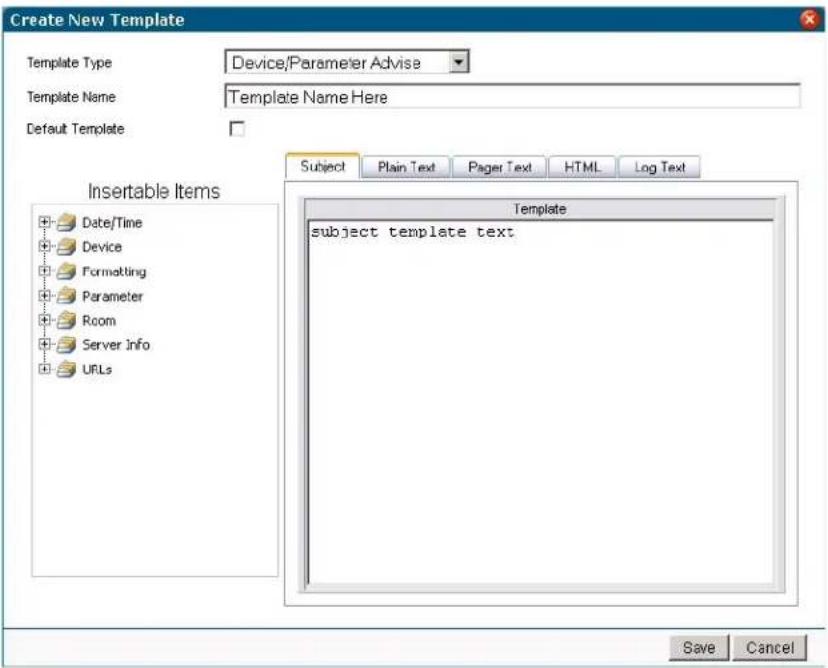
FIG. 156 Create New Template Page
| Configure Notification Template | |
| Template Type Name | There are seven different types of templates:Device/Parameter Advise - These template are used to send notifications when a parameter that was previously outside its normal operating range returned to its normal operation range.Device Parameter Alert - These templates are used to send notifications when a parameter's value is outside it's normal operating rangeModified Appointment - These templates are used to send notifications when an existing appointment has been modified.New Appointment - These templates are used to send notifications when a new appointment has been added.New NetLinx System - These templates are used to send notifications when a new NetLinx system connects to the RMS application.Server Status - These templates are used to send notifications when the RMS application server is started.System Communication Error - These templates are used to send notifications when a system communication error occurs. |
| Template Name | The friendly name of the notification template. |
| Configure Notification Template (Cont.) | |
| Default Template | When enabled, this is the default setting and format for your notifications. |
| Insertable ItemsDate/Time • [DATE] - Short Date in localized format. In US, it would be "mm/d/yy" e.g. "10/3/06"[LONGDATE] - Long Date in localized format. In US, it would be "month day, yyyy" i.e."October 3, 2006"[Room.Time] - Current localized room time. This is calculated based on the timezone the room is configured for. e.g. "12:05 AM"[Room.TimeZoneName] - The timezone for the room[Server.Time] - Current localized server time, e.g. "12:05 AM"[Server.UTF] - Current localized server time in UTC, e.g. "6:05 AM"[TIME] - Current localized time, e.g. "12:05 AM" | |
| Device Device that contains the parameter change that invoked the notification[Device.Description] - Device textual description[Device.DPS] - Device:Port:System identifier[Device.Manufacturer] - Device manufacturer name[Device.Model] - Device model name/number[Device.Name] - Device name[Device.NetLinxDeviceAddress] - NetLinx device address[Device.NetLinxDeviceAddressType] - NetLinx device address type, e.g. "RS-232", "TCP/IP", "AXLINK" or "ICSNET"[Device.NetLinxDeviceSerialNumber] - The serial number for the NetLinx device[Device.NetLinxDeviceType] - The NetLinx device type name. e.g. "Volume Control" or "NI Master"[Device.NetLinxDeviceVersion] - The version of the NetLinx device[Device.RFIDTagID] - The RFID Tag of the device[Device.SerialNumber] - Device serial number | |
| Formatting • [CRLF] - Carriage Return & Line Feed (0x0D, 0x0A)[TAB] - Tab (0x09) | |
| Parameter Parameter change that invoked the notification[Parameter.LastUpdate] - The UTC time the parameter was last updated[Parameter.Name] - The parameter textual name[Parameter.OriginalValue] - The original parameter value before the parameter change[Parameter.ParameterType] - The parameter type, e.g. "Number" or "String"[Parameter.StatusType] - The parameter's status type. e.g. "Help Request" or "Control System Error"[Parameter.Threshold] - The parameter's threshold value, the value that will be compared against to determine if the parameter change has tripped the parameter[Parameter.ThresholdCompare] - The parameters threshold comparison expression that is used to determine if the parameter change has tripped the parameter[Parameter.Units] - The units of measure for the parameter, e.g. "hours", "minutes" etc.[Parameter.UpdateValue] - The update value of the last parameter change[Parameter.Value] - The current value of the parameter after the parameter change has been applied | |
| • Room | Room that contains the device that contains the parameter change that invoked the notification• [Room.MapURL] - URL link to the room's map• [Room.Name] - Room Name• [Room.Phone] - Room's phone number |
| • Server Info The RMS Server• [Program.Name] - This is the name of the RMS vertical market that was selected. e.g. "MeetingManager" or "WorshipManager"• [Server.HostName] - Network hostname of RMS server• [Server.IPAddress] - IP Address of RMS server | |
| • URLs • [Device.ManualURL] - URL link to the device's user manual• [Device.URL] - UTL link to the device page in the RMS web pages• [Parameter.URL] - URL link to the parameter view page in the RMS web pages• [Server.HotListUrl] - URL link to the RMS HotList web page• [Server.InternalLogURL] - URL link to the RMS Internal Log web page• [Server.SystemStatusURL] - URL link to the RMS system status web page• [Server.WebBasePath] - URL link to the RMS web pages | |
| • Template Text Area | This is the area where you compose your notification. Use both text and insertable items.• Subject - This is a brief description for the subject line of the notification.• Plain Text - Plain text with no paragraph formatting.• Pager Text - Text that is capable of being sent to pagers.• HTML - Formatted text with HTML support including hyperlinks.• Log Text - Plain text set for logging. |
Viewing a Notification Template
- Select Configuration > Notification Templates in the menu on the left side of the RMS application. The Configure Notification Template page opens.
- Select a template from the table and click View.
Creating a new Notification Template
- Select Configuration > Notification Templates in the menu on the left side of the RMS application. The Configure Notification Template page opens.
- Click Create New Template.
- Select a Template Type.
- Type a friendly name for the template.
- If desired, designate the template as the default notification.
- Type a Subject for the notification.
- Click the tab of the type of message to use, e.g., Plain Text, Pager Text, HTML or Log Text.
- Compose your notification message. When entering template text, you can insert placeholders by selecting an item from Insertable Items and double-clicking the item. The item is inserted at the current cursor location. Placeholders are replaced with data specific to the event when the notification is generated.
- Click Save to save, Cancel to cancel.
Deleting a Notification Template
- Select Configuration > Notification Templates in the menu on the left side of the RMS application. The Configure Notification Template page opens.
- Select a template from the table right-click and select Delete.
Copying a Notification Template
- Select Configuration > Notification Templates in the menu on the left side of the RMS application. The Configure Notification Template page opens.
- Select a template from the table right-click and select Copy. This will create a copy of your selected template.
Prestige Levels Page
Prestige levels are optional but they can help users find a room that meets their needs through the RMS application's room search capabilities. Prestige levels are used to classify rooms based on aesthetics. You can use between one and ten prestige levels based upon the requirements of your facility, via options in the Prestige Levels page (FIG. 157).
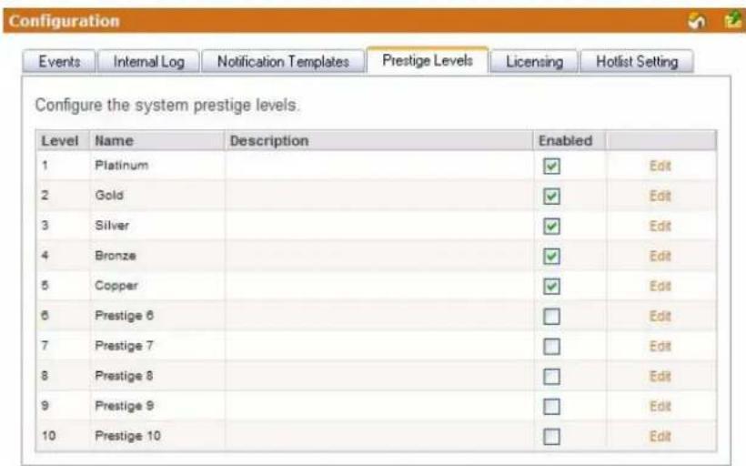
FIG. 157 Prestige Levels Page
| Prestige Levels | |
| • Level The level of Prestige with Level 1 being the highest. | |
| • Name A friendly name for the Prestige Level. | |
| • Description A brief description of the Prestige Level. | |
| • Enabled When checked, this Prestige Level is available to be assigned to a room. |
Editing Prestige Levels
- Select Configuration > Prestige Levels in the menu on the left side of the RMS application. The Prestige Levels page opens.
- Select the prestige level by clicking Edit. The Name and Description fields are now active.
- Type a new Name and/or Description for the prestige level.
- Click Save to save, Cancel to cancel.
Enabling/Disabling Prestige Levels
- Select Configuration > Prestige Levels in the menu on the left side of the RMS application. The Prestige Levels page opens.
- To enable a selected level, place a check in the box under the column Enabled. Remove the check to disable that prestige level.
System Licensing Page
The RMS application is licensed by the total number of rooms that can be configured within the system. For each room required, you need either one Scheduling license, one Asset license, or both.

To obtain an RMS License, please contact AMX at 800-222-0193, by email at service@amx.com or contact your AMX dealer.
When adding a room, the licensing information is displayed to let you know how many licenses you have remaining (FIG. 158).
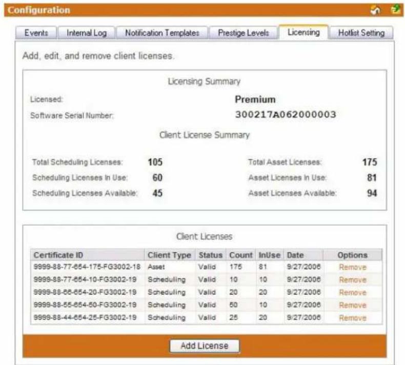
FIG. 158 System Licensing Page
| System Licensing | |
| • Licensed The type of RMS server license. Standard indicates a constrained license while Premium is a fully functioning version of RMS. | |
| • Software Serial Number The Serial number of the server software and the license key. | |
| • Total Scheduling Licenses | The total number of scheduling licenses installed. |
| • Scheduling Licenses In Use The number of scheduling licenses in use. | |
| • Scheduling Licenses Available The number of scheduling licenses available for use. | |
| • Total Asset Licenses The total number of asset licenses installed. | |
| • Asset Licenses In Use The number of asset licenses in use. | |
| • Asset Licenses Available The number of asset licenses available for use. | |
| • Certificate ID | This table lists the client certificates installed on the license key. Each client certificate has a certificate ID. |
| • Client Type | The client type of the license, either Asset or Scheduling. |
| System Licensing (Cont.) | |
| • Status The current status of the | license Certificate ID. Invalid licenses do not function. |
| • Count Each client certificate has | a quantity of client licenses. |
| • InUse The number of licenses in | use on the selected Certificate ID. |
| • Date The date the Certificate ID | was registered with the RMS server. |
| • Options Remove - Removes the | Certificate ID and all of its licenses from the RMS server. |
If the number of NetLinx connected systems is greater than the number of licenses available you can still track them in the Unassigned NetLinx Systems section of the HotList. You will need more Client Licenses before you can create rooms for these systems.
The RMS application can run without a license key. In Standard mode, you can run the RMS application with limited capabilities for previewing the functionality of the software:
- No rooms without masters
- No control function macro creation, scheduling, or execution
- No external scheduling
- Only 1 user other than admin
● Standard mode management limited to five rooms
● Only one notification recipient

Refer to the Licensing Summary - Asset Licenses vs. Scheduling License section on page 24 for a detailed listing of features provided by each asset type.
Checking Client Licensing Information
- Select Configuration > Licensing in the menu on the left side of the RMS application. The System Licensing page opens.
- All available license information is listed in this table.
Adding a Client License
- Select Configuration > Licensing in the menu on the left side of the RMS application. The System Licensing page opens.
- Click Add License to enable the Add Client License section.
- Type the AMX provided License Certificate and License Key in the available fields.
- Click Save to save, Cancel to cancel.
Removing a Client License
- Select Configuration > Licensing in the menu on the left side of the RMS application. The System Licensing page opens.
- Click Remove for the selected license.
- Confirm the removal of the license.
Hotlist Settings Page
The Hotlist Settings page allows you to create custom system responses to Help and Maintenance requests (FIG. 159).
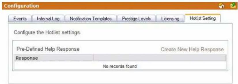
FIG. 159 Hotlist Settings Page
| Hotlist Settings Page | |
| • Response A text field for input of custom response. | |
| • Insert Adds new Help response. | |
| • Cancel Exits the text Create New Help Response page without creating response. |
Creating a New Help Response
- Select Configuration > Hot List Setting in the menu on the left side of the RMS application. The Hotlist Settings page opens.
- Click Create New Help Response to enable the new help response defining area.
- Type your help response in the text field.
- Click Insert to save, Cancel to cancel.
Editing a Help Response
- Select Configuration > Hot List Setting in the menu on the left side of the RMS application. The Hotlist Settings page opens.
- Select your help response and click Edit to enable the edit help response defining area.
- Edit the help response in the text field.
- Click Update to save, Cancel to cancel.
Deleting a Help Response
- Select Configuration > Hot List Setting in the menu on the left side of the RMS application. The Hotlist Settings page opens.
- Select your help response and click Delete.
Configuration Page
Help Page
Overview
The Help page is a list of links that can aid you in getting the best uses out of the RMS application.
| Help Page | |
| • About RMS application | Opens the About RMS Application Page section on page 165, this page contains copyright information about the application. |
| • Administrator's Guide Launches | the PDF version of the Administrator's Guide. |
| • User's Guide Launches | the PDF version of the User's Guide. |
| • Version Information | Launches the Version Information Page, this page lists the build version number for the RMS application. |
| • View Readme | Launches the View Readme Page, this page lists any feature changes to the RMS application since last release. |
| • System Diagnostics | System Diagnostics provides you with status information for the overall RMS server as well as the status for connected devices. |
About RMS Application Page
This page contains copyright information and version for the application.
Administrator's Guide
In addition to the features covered in the User's Guide, the Administrator's Guide covers room and user management, system status, and other system upkeep information.
User's Guide
The User's Guide provide information for scheduling rooms and creating notifications for yourself.
Version Information Page
The Version Information page provide the name of the application, build version and date and the name, version and date for all associated RMS components loaded on the server.
View Readme
The Readme lists any known issues associated with the RMS application build and chronicles any changes that have occurred since the last build of the application.
System Diagnostics
Status Page
The Status page lists all components parts of the RMS server application, this page is a pass-fail diagnostics tool. Any error encountered is indicated with a red X; otherwise, all passing systems are shown with a green check.
Checking System Status
- Select Help > System Diagnostics in the menu on the left side of the RMS application. Click the Status tab at the top of the page. The Status page opens.
- Click either Services, Licensing, Product, Reporting, Server, Logging, Database, SMTP, Dependencies, SNMP, Permissions, or ASP to jump to that section on the page.
- Click Refresh at any time to refresh the page for server status.
Connections Page
The Connections page is used to display the RMS server connection settings and all current TCP/IP connections to the RMS Server from NetLinx masters. The connection listing includes an internal connection identifier, the system identifier and the remote IP address and port of the NetLinx connection. In addition to listing the connections, you can click the red "X" to disconnect any single connection.
- Refresh Connection List - Repolls the connections.
- Restart Connection Server - Restarts the RMS connection server.
Checking RMS connections
- Select Help > System Diagnostics in the menu on the left side of the RMS application. Click the Connections tab at the top of the page. The Connections page opens.
- Click Refresh at any time to refresh the page.
Restarting Connection Server
- Select Help > System Diagnostics in the menu on the left side of the RMS application. Click the Connections tab at the top of the page. The Connections page opens.
- Click Restart Connection Server at any time to restart the connection server for RMS.
Resources Page
When checked, displays all the localization resource key names for each text string that has been localized.
The text displayed gets localized to the foreign language of choice and each string in the system must have a resource key by which to look up the display string in the language resource files.
This tool allows you to verify that the strings are localized and get the resource key name in the event that any changes are made to any specific string, label, text field, or button.
| Resources | |
| • Display Resource Keys | Replaces every resource string with the key name that is used to lookup the string value in the resource file.This option is useful to understand exactly what key a particular field is using. This is also a good way to ensure a field is properly defined. |
| • Append Culture Code to Strings | When enabled, this option appends to each resource string the current culture code in parentheses. If the string is coming from the "invariant" culture, no code is appended.This option will help to understand if a particular string is pulled from a culture specific resource file (e.g. "es-MX"), a culture neutral resource file (e.g. "es"), a product specific resource file (e.g. "ClassroomManager.es") or from the invariant resource files.The "invariant" resources are the default resource files used when no resource key can be found in a culture localized resource file. For RMS this is US English. |
| • Display Resource Lookup Table | When enabled, this option displays a table of resource information used for the current page.This table always appears at the bottom of the rendered page. |
Displaying/Hiding Resource Keys
- Select Help > System Diagnostics in the menu on the left side of the RMS application. Click the Resources tab at the top of the page. The Resources page opens.
- Place a check in the box Display Resource Keys to enable. Removing the check disables this feature.
Appending Culture Codes to Strings
- Select Help > System Diagnostics in the menu on the left side of the RMS application. Click the Resources tab at the top of the page. The Resources page opens.
- Place a check in the box Append Culture Code to Strings to enable. Removing the check disables this feature.
Displaying the Resource Lookup Table
- Select Help > System Diagnostics in the menu on the left side of the RMS application. Click the Resources tab at the top of the page. The Resources page opens.
- Place a check in the box Display Resource Lookup Table to enable. Removing the check disables this feature.
Debugging Page
The Debugging page allows you to enable detailed diagnostics information on the RMS server for tracking and identifying errors as they occur at the server level. The debug server provides a console view for diagnostics and debug messages.
To connect to the debug console, use a TELNET client and connect to the RMS server on the specified port.
| Debugging | |
| • Debug Server Enabled | When checked, RMS creates a debug server.Note: The Debug Server Enabled option should not be left on in a production running environment. This option is used for support and in-depth diagnostics of the RMS system. While enabled, the system will generate a high volume of internal diagnostics messages and could significantly impact the overall performance of the RMS application. |
| • Debug Server Port | The port number for the Debug server. The default value is port 24. |
| • Open Debug Session | Launches a telnet session to the Debug server. |
| • Save Enacts changes to the Debugging server. | |

If configured to use port number 24, please note that this is not the default TELNET port and you will have to specify the port number when establishing a TELNET based connection. If a firewall or router is blocking this port you will not be able to remotely access the RMS debug console.
Setting Debug Options And Debugging The RMS Server
- Select Help > System Diagnostics in the menu on the left side of the RMS application. Click the Debugging tab at the top of the page. The Debugging page opens.
- Place a check in the box Debug Server Enabled to activate the debugging tool.
- Set the Debug Server Port number in the field provided. The default port is 24.
- Click the link next to Open Debug Session to open a telnet session to the RMS server.
- Click Save when you are finished.
Help Page
Sitemap Page
Overview
The Sitemap is a hierarchical list of links to every page available within the RMS application; this page is restricted and populated according to the role of the user currently logged in to the RMS application (FIG. 160).
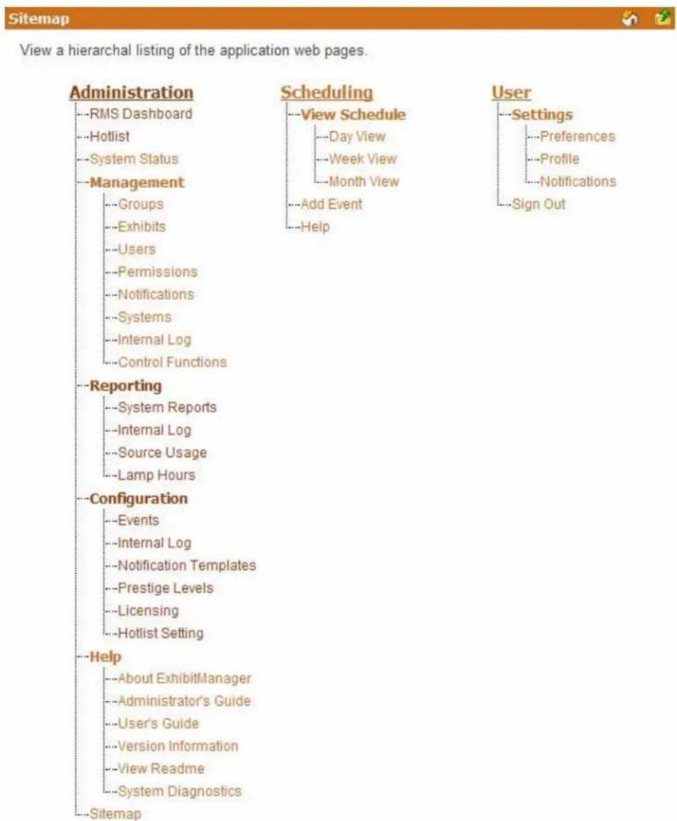
FIG. 160 Sitemap Page
Click on any link to go directly to the desired application feature.
Sitemap Page
RMS Scheduling Page
Overview
The RMS Scheduling page provides links to viewing the application schedule, creating an entry to the schedule, and access to the PDF version of the User's Guide.

NOTE
RMS is capable of supporting multiple (up to 12) instances of Scheduling on a single NetLinx Master. If you intend to run multiple instances of Scheduling on a Master, then that Master should be dedicated solely to RMS Scheduling.
View Schedule Page
The RMS Scheduling page provides links to viewing the schedule in either Day, Week or Month view.
Day View Page
The Day view lists all appointments for the selected room on a particular date. Double-clicking within the hour launches the Add Appointment Page section on page 173.
| Day View | |
| Select a room A drop down list for all rooms available for schedule. | |
| Select Date A navigation calendar that indicates the current date and allows you to select other dates by clicking.Appointments with a "lock" icon indicate that you do not have the proper permissions to access that appointment. Appointments with a "key" icon indicate password protection, and you must provide the correct password to access the appointment.Today brings you back to the current date. | |
| Room Information:Name The name of | the room. |
| Location The location of the room. | |
| Occupancy The maximum number of individuals held in this room. | |
| Timezone This is the time zone setting for the room. | |
| Equipment This is the equipment list for the room. | |
Opening Day View
- Select View Schedule > Day View in the menu on the left side of the RMS application. The Day View page opens.
- You can change rooms by selecting them from the drop down menu, Select a room.
- You can change the day in view by clicking on another day in the calendar under Select Date. Navigate back to the current day by clicking Today.
- In the event there is an appointment for that room you will see the Room Details.
- Mouse over the appointment to display Duration, End Time, Start Time, Recurring, Scheduled By, Room Details, Location and Appointment Details. Appointments with a lock indicate you do not have proper permissions to view; appointments with a key require a password.
- Double click the appointment to edit.
Week View Page
The Week view lists all appointments for the selected room for a particular 7 day period. Double-clicking on any day in the week will open the Day View Page section on page 171.
| Week View | |
| Select a room A drop down list for all rooms available for schedule. | |
| Select Date A navigation calendar that indicates the current date and allows you to select other dates by clicking.Appointments with a "lock" icon indicate that you do not have the proper permissions to access that appointment. Appointments with a "key" icon indicate password protection, and you must provide the correct password to access the appointment.This Week brings you back to the current week. | |
| Room Information:Name The name of | the room. |
| Location The location of the room. | |
| Occupancy The maximum number of individuals held in this room. | |
| Timezone This is the time zone setting for the room. | |
| Equipment This is the equipment list for the room. | |
Opening Week View
- Select View Schedule > Week View in the menu on the left side of the RMS application. The Week View page opens.
- You can change rooms by selecting them from the drop down menu, Select a room.
- You can change the week in view by clicking on another day in the calendar under Select Date. Navigate back to the current day by clicking This Week.
- In the event there is an appointment for that room you will see the Room Details.
- Mouse over the appointment to display Duration, End Time, Start Time, Recurring, Scheduled By, Room Details, Location and Appointment Details. Appointments with a lock indicate you do not have proper permissions to view; appointments with a key require a password.
- Double click the appointment to edit.
Month View Page
The Month view lists all appointments for the selected room for a particular 6 week period. Double-clicking on any day in the month will open the Day View Page section on page 171.
| Month View | |
| Select a room A drop down list for all rooms available for schedule. | |
| Select Date | A navigation calendar that indicates the current date and allows you to select other dates by clicking.Appointments with a "lock" icon indicate that you do not have the proper permissions to access that appointment. Appointments with a "key" icon indicate password protection, and you must provide the correct password to access the appointment.This Month brings you back to the current month. |
| Room Information:Name The name of | the room. |
| Location The location of the room. | |
| Occupancy The maximum number of individuals held in this room. | |
| Timezone This is the time zone setting for the room. | |
| Equipment This is the equipment list for the room. | |
Opening Month View
- Select View Schedule > Month View in the menu on the left side of the RMS application. The Month View page opens.
- You can change rooms by selecting them from the drop down menu, Select a room.
- You can change the month in view by clicking on another day in the calendar under Select Date. Navigate back to the current day by clicking This Month.
- Double click any day to change to Day View Page section on page 171.
Add Appointment Page
The Add Appointment page allows you to create and schedule your own event. MeetingManager allocates the room for the designated time.
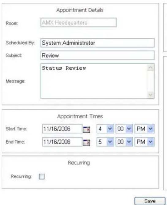
FIG. 161 Add Appointment Page
| Add Appointment | |
| • Room A drop down list of rooms available for scheduling within the RMS application.Search allows you to find a room base on your needs. See the Room Search Page section on page 177. | |
| • Scheduled By: | A text field to provide the name of the meeting scheduler. This field is populated by the RMS application. |
| • Subject The subject line for the meeting purpose. | |
| • Message A larger text field for any additional information pertaining to the meeting. | |
| • Start Time: A text field for the date (mm/dd/yyyy) the meeting has been scheduled to start.You can click on the calendar icon to select the date. The three following drop down menus represent hour, minute, and designation for ante-meridiem vs. post-meridiem (AM/PM), in that order. | |
| • End Time: A text field for the date (mm/dd/yyyy) the meeting has been scheduled to end. You can click on the calendar icon to select the date. The three following drop down menus represent hour, minute, and designation for ante-meridiem vs. post-meridiem (AM/PM), in that order. | |
| Add Appointment (Cont.) | |
| Recurring: When checked | this option makes the meeting a recurring event. |
| Pattern:Daily Makes the recurring | scheduled meeting a daily pattern.Every __ days(s) - text field for number of days between daily recurring meetingEvery weekday - executes the daily meeting only Monday - Friday |
| Weekly Makes the recurring | scheduled meeting a weekly pattern.Every __ week(s) on - text field for number of weeks between weekly recurring meetingSelect the day the weekly scheduled meeting is to occur. More than one day can be selected. |
| Monthly Makes the recurring | scheduled meeting a monthly pattern.Day __ of every __ month(s) - the drop down menus allow you to set what day of the month the recurring meeting executes and how many months between each occurrence.The __ of every __ month(s) - this setting allows you to pick either the first, second, third, fourth, or last day of each week, and the number of months between each occurrence. |
| Yearly Makes the recurring | scheduled meeting a yearly pattern.Every __ - the drop down menus allow you to set the month and day the recurring meeting occurs.The __ of - this setting allows you to pick either the first, second, third, fourth, or last of each week of a specified month. |
| Lifetime:No end date The scheduled | recurring meeting does not end. |
| End after _ occurrences | The scheduled recurring meeting ceases to run upon reaching the user defined parameter. |
| End by: Either type the date | the scheduled recurring meeting is to end or select the date from the calendar icon. |
Appointment Details Page
The Appointment Details page allows you to assign text and images to the appointment. MeetingManager executes any predefined Control Functions, if available, and provides welcome text to your attendees (FIG. 162).
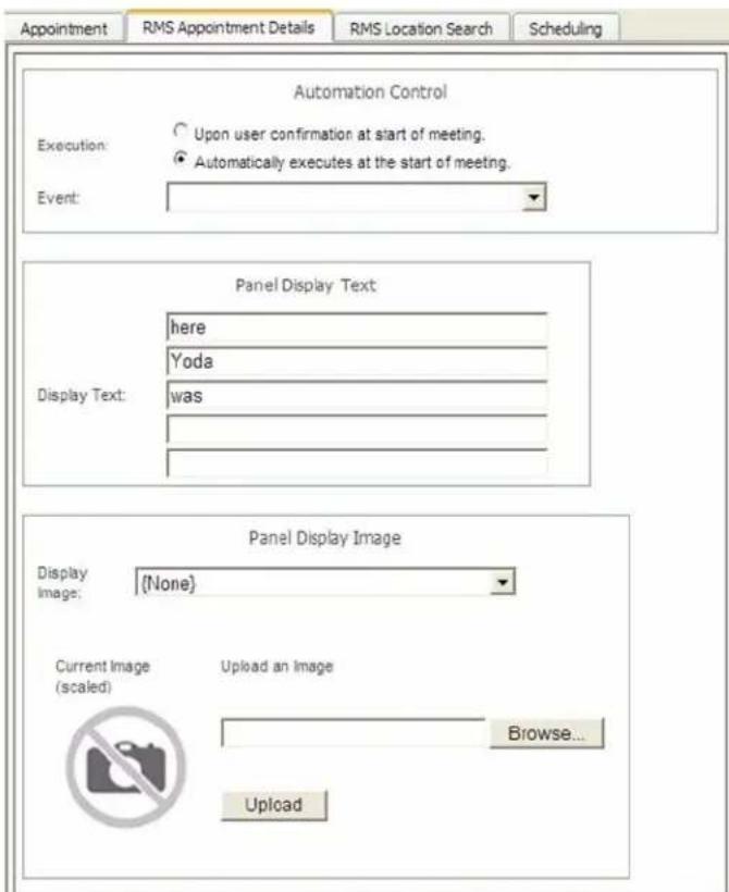
FIG. 162 Appointment Details Page
| Appointment Details | ||
| • Automation Control Execution | • Upon user confirmation at start of appointment - The meeting coordinator must select to run preset at the time of the meeting from within the room.• Automatically executes at the start of the appointment - The preset runs at the Start Time of the meeting. | |
| Event Drop down menu list of available control function macros in your selected room. This event executes based on the Execution designation. | ||
| • Panel Display Text Display Text Up to 5 lines of text. Type a welcome message as it is to be displayed on the pane in the room. The welcome message can provide your attendees with a warm greeting. This feature is only available if a panel is available for display. | ||
| Appointment Details (Cont.) | ||
| • Panel Display Image Display Image | RMS supports custom image display for assisting in informing your attendees. The following formats are supported:Note: This feature is only available if a G4 panel is available for display. | |
| • BMP (Microsoft Windows Bitmap)• JPG (Joint Photographics Experts Group)• PNG (Portable Network Format)• ICO (Microsoft Windows Icon)• TIF (Tagged Image File Format) | • TGA• PCX• W B M PWMF (Microsoft Windows Metafile) | |
| Upload an Image Clicking this link enables the file upload area of the page.•Browse... - Opens the file browse window.•Upload - Loads the image file to the appointment.This feature is only available if a G4 panel is available for display. | ||
Creating an Appointment
- Select Add Appointment in the menu on the left side of the RMS application. The Add Appointment page opens.
- In the drop down menu, Room, select the room that will host the appointment or search for a room by clicking Search (See Conducting a Room Search section on page 178).
- Type a Subject for the appointment in the space provided.
- Type a Message providing more information about the appointment in the larger text field.
- Set the Appointment Times, start, end and if it is a recurring appointment. If the appointment is recurring, set the Pattern and Lifetime of the appointment.
- Click the RMS Appointment Details tab to access the Appointment Details page.
- Set the Automation Control, if applicable, to set the preset to execute manually or automatically. Select the Control Event from the drop-down menu.
- Enter display text in the lines provided. These lines of text appear on the panels in the room at the time of the appointment. This step is optional.
- Select a panel display image from the drop-down menu, or click Upload Image. If you selected Upload Image, either type the path or browse to the file you wish to use. Click Upload to load the file. This step is optional.
- Click Save to save, or Cancel to cancel.
Creating an Appointment with an External Scheduler
When used in conjunction with an external scheduling system, e.g., Lotus Notes, RMS must check the scheduling system for changes and updates. RMS utilizes a trolling engine to log into the external scheduling system, check for new and updated appointments, and then sync those appointments within the RMS database. All detected changes can then become notifications RMS sends to designated users.
-
Within your external scheduler, e.g., Lotus Notes and Outlook, create a meeting (appointment). Your room selection is made at this time within the external scheduler.
-
Once RMS has detected the new appointment, an email notification is sent to the appointment scheduler (see FIG. 163). Click on the provided Appointment URL to set presets, welcome messages, and welcome images in the Add Appointment page. See the Add Appointment Page section on page 173 for more details on the page opened.

The Add Appointment Page disables the Appointment Details, Appointment Times, and Recurring features, these parts of the appointment can only be changed in the external scheduler.
- Set the Automation Control, if applicable, to set the preset to execute manually or automatically. Select the Control Event from the drop-down menu (FIG. 163).
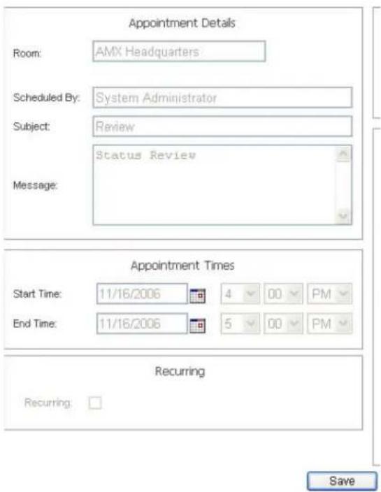
FIG. 163 Configure External Scheduler Appointments Page
4. Click the RMS Appointment Details tab to access the Appointment Details page.
5. Enter display text in the lines provided. These lines of text appear on the panels in the room at the time of the appointment. This step is optional.
6. Select a panel display image from the drop-down menu, or click Upload Image. If you selected Upload Image, either type the path or browse to the file you wish to use. Click Upload to load the file. This step is optional.
7. Click Save to save, or Cancel to cancel.
Included in the RMS SDK are touch panel files that allow the user to execute manual presets, send help and maintenance requests, extend the appointment, and view schedules.
Room Search Page
The Room Search page allows you to search for a specific room or find one based on your appointment needs. Room searching is a feature of internal RMS scheduling.
| Room Search | |
| • Room Name The name of the room. | |
| • Location The location of the room | |
| • Number of Seats Needed | This is the number of seats for the room. |
| • Minimum Prestige Level | Select the level from the drop down list. This is the prestige level for the room. |
| • Equipment Needed | This is the equipment listed for any room. All equipment items should be separated by a comma. You can also select devices that appears in the available list. You can select more than one piece of equipment from this list by pressing the CTRL key on your keyboard and clicking the appropriate devices. |
| Room Search (Cont.) | |
| • Search for specific Date/Time | When checked, RMS will search for a room that meets your parameters within a window of time. |
| • Date Needed Type the date the room is needed or click the calendar icon to select a date. | |
| • Duration The time in hours and minutes the room is needed. | |
| • Search for specific time or search in a range of times Start Time | The desired start time for the appointment.The three following drop down menus represent hour, minute and designation for ante-meridiem vs. post-meridiem, in that order. |
| Search By Range | RMS searches the availability of a room based between the Start and End time range. The three following drop down menus represent hour, minute and designation for ante-meridiem vs. post-meridiem, in that order. |
Room Search Results Page
Based on the criteria used in the Room Search Page section on page 177, choose the room to use from the list displayed on this page.
| Room Search Results | |
| • Room The name of the | room. |
| • Location The location of | the room |
| • Prestige Level Select the level from the drop down list. This is the prestige level for the room. | |
| • Num of Seats Needed | This is the number of seats for the room. |
| • Option Select - Selects | the room for use within the appointment. |
Conducting a Room Search
- Select Add Appointment in the menu on the left side of the RMS application. The Add Appointment page opens.
- Click Search to open the Room Search page.
- Enter the room criteria in the spaces provided.
- Click Search.
- Find a room that fits your needs and click Select to allocate it to your appointment.
RMS User Page
Sign in Page
The Sign in page is the access page for RMS.
The Username and Password are unique to each user.
How Do I Sign In To RMS?
- Type the URL of your RMS server into your web browser.
- Type your username in the field provided.
- Type your password in the field provided.
- Click Sign In.
Preferences Page
The Preferences page allows each user to customize aspects of their RMS experience.
| Preferences | |
| • Language A drop down list of available translations for the RMS application. RMS detects the language of your browser and uses that unless otherwise specified.Your language preference is stored at the RMS server level and it is no longer necessary to enable cookies on your browser. | |
| • Home Page: A drop down list of available RMS application web pages that can be designated as the home page; this will be the first page loaded upon a successful login. | |
| • Column Sorting: | Clicking Reset All Data Grids returns each table within RMS to the default sort method. |
| • Scheduling View Hours: | A drop down list for the number of hours displayed in the scheduling view of RMS. |
Setting the Default Language
- Select Settings > Preferences in the menu on the left side of the RMS application. The Preferences page opens.
- Select your language from the drop down menu, Language. Auto Detect will use the language settings of your web browser.
- Click Save to save the setting.
Setting the Home Page
- Select Settings > Preferences in the menu on the left side of the RMS application. The Preferences page opens.
- Select your home page from the drop down menu, Language. The home page is your default page upon sign in and any time you select Home on any RMS page.
- Click Save to save the setting.
Resetting Column Sorting
- Select Settings > Preferences in the menu on the left side of the RMS application. The Preferences page opens.
- Click Reset All Data Grids.
- Click Save to save the setting.
Setting Scheduling View Hours
- Select Settings > Preferences in the menu on the left side of the RMS application. The Preferences page opens.
- Select the block of hours from the drop down menu,
- Click Save to save the setting.
User Profile Page
The User Profile page allows the user to change personal information and designate how the RMS application interacts with them.
| User Profile | |
| • Username: This is your username in relation to logging into RMS. This value is required. | |
| • Account Enabled: | When this box is checked, a user is valid and can log into RMS. |
| • Password: This is the password associated with your user account, used at the time of login. This value is required. | |
| • Confirm Password: Retype password for confirmation. This value is required. | |
| • First Name: The first name of the user assigned to this account. This value is required. | |
| • Last Name: The last name of the user assigned to this account. This value is required. | |
| • Phone User's phone number. | |
| • Mobile Phone: User's mobile phone number. | |
| • Fax: User's fax number. | |
| • Email 1,Email 2,Email 3, Email 4: | User's email address. The drop down menu allows you designate the email address as the default account, send a plain text message, HTML message, or Pager Message.Test sends a message to the email address.When established, RMS will use the account to send notifications.You can enter up to 100 characters for an email address. |
| • Pager Provider: | A drop down list of pager providers. This option is only available if the RMS server has been configured to use Simple Network Paging Protocol (SNPP). |
| • Pager Number: The number for contacting the pager with notifications. | |
| Notification Time Span:Disable Notifications | |
| When selected, notifications are not sent to this user. | |
| Always Send Notifications | When selected, all notifications are sent to this user. |
| Only Send Notifications On: | The RMS server will send notification only within the designated parameters. Place a check in the box next to the days of the week you would like to receive notifications.Start Time/End Time - The three drop down menus represent hour, minute and designation for ante-meridiem vs. post-meridiem (AM/PM), in that order.Notifications are only sent between the start and end times. |
Editing Your User Profile
- Select Settings > Profile in the menu on the left side of the RMS application. The User Profile page opens.
- Change any of the fields but be sure to include all of the required information.
- Click Save to save the setting.
Changing Your User Password
- Select Settings > Profile in the menu on the left side of the RMS application. The User Profile page opens.
-
Click the Profile tab at the top of the page.
-
Enter your new Password in the provided field.
- Confirm Password in the provided field.
- Click Save to save the setting.
Setting User Notification Time Span
- Select Settings > Profile in the menu on the left side of the RMS application. The User Profile page opens.
- Click the Profile tab at the top of the page.
- In the section, Notification Time Span, select either Disable Notifications, Always Send Notifications, or Only Send Notification On. If you selected Disable Notifications or Always Send Notifications, no more information is needed and you can click Save.
- If you selected Only Send Notifications On, set the sending parameters of the notification.
- Click Save to save the setting.
User Notifications Page
The User Notifications page is a listing of all notifications you are designated to receive. Additionally, you can create new notifications for yourself.
If the user is receiving notifications because they are a member of a user role that has been assigned a notification, they will see this in the notifications listing, but will not be able to edit it. This can only be changed by a user administrator via the Management - Notifications Page section on page 88.
| User Notifications | |
| • Group Name The name of the group or groups receiving the selected notification. | |
| • Room Name The name of the room being monitored for the notification. | |
| • Status Type The type of status monitored for the notification. | |
| • User The username receiving the notification. | |
| • Email User's email address. | |
| • Pager The pager number for the user. | |
| • Options Edit - Launches the Create New Notification Page.Delete - Deletes the selected notification. |
Create New Notification Page
You can assign RMS to track status types for rooms and groups and then provide you with notifications.
| Create New Notification Page Options | |
| Enabled When checked, the notification is active. | |
| Groups/Rooms A drop down list of groups and rooms in the RMS system. Selecting one tracks it for the purposes of the notification. This field is required. | |
| Users The username receiving the notification. This field is required. | |
| Status Type The type of status monitored for the notification.• Control System ErrorThis status type is triggered when the RMS server detects an error within the NetLinx master control system.• Equipment UsageThis status type is triggered when any monitored equipment is used.• Help RequestThis status type is triggered when the RMS server reports receiving a help request.• MaintenanceThis status type is triggered when the RMS server reports receiving a request for maintenance. | |
| Status Type (Cont.) | Modified AppointmentThis status type is triggered when an existing appointment is modified for a room either through the internal scheduler or as detected by the RMS Scheduling manager for an external scheduling system.NetworkThis status type is triggered when the network creates an error.New AppointmentThis status type is triggered when a new appointment is added for a room either through the internal scheduler or as detected by the RMS Scheduling manager for an external scheduling system.New NetLinx SystemThis status type is triggered when a new NetLinx system connects to the RMS server.Not AssignedThis status type is triggered when a detected NetLinx system has not been assigned.Room Communication ErrorThis status type is triggered when the RMS server software encounters a problem communicating with a room within the RMS system.SecurityThis status type is triggered when the RMS server reports a security parameter has been met.Server StatusThis status type is trigger when the RMS server software starts up.System Communication ErrorThis status type is triggered when the RMS server software encounters a problem communicating with an external communication system, such as SMTP or SNPP. This field is required. |
| Emails & Pager | User's email addresses. The pager number for the user. You can enter up to 100 characters for an email address. |
Creating new User Notifications
- Select Settings > Notifications in the menu on the left side of the RMS application. The User Notifications page opens.
- Click Create New Template to launch the Create New Notification Page section on page 181.
- Place a check in the box, Enabled.
- Select a room or group from the drop down list Groups/Rooms.
- Select a Status Type to monitor from the drop down list.
- Select the email and/or pager accounts the notification will use by placing a check in the box.
- Click Save to save, Cancel to cancel.
Sign Out Page
The Sign Out page confirms your selection to exit the RMS application; select Yes or No.
Signing Out of RMS
- Select Sign Out in the menu on the left side of the RMS application.
- Click Yes to confirm.
RMS Touch Panel Pages
Overview
Included within the RMS SDK are G4 touch panel pages for your RMS installation. Based on NetLinx code configuration, the panel boots up as either a Welcome or In-room panel page.
RMS Welcome Page
This page is displayed on the panel outside of the meeting room.
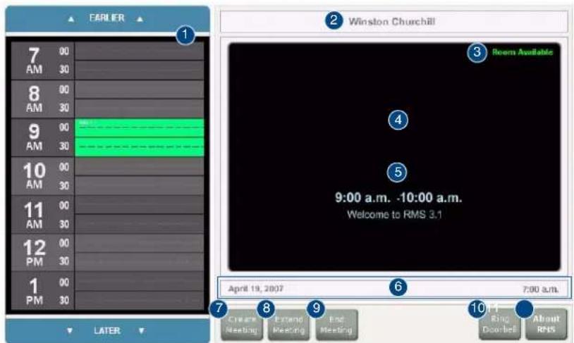
FIG. 164 RMS Welcome Page
| RMS Welcome Page | ||
| 1 | Meeting room schedule | The schedule for the meeting room. Navigate back and forward through the schedule using the EARLIER and LATER buttons at the top and bottom of the schedule.Select a reserved time to view its information. |
| 2 | Meeting room name The name of the meeting room. | |
| 3 | Meeting room status | The current status of the meeting room; Room Available or Room In Use. |
| 4 | Welcome image If configured, a welcome image appears in this space. | |
| 5 | Meeting information The time span and welcome text of a meeting selected in the meeting room schedule. | |
| 6 | Date and time The current date and time. | |
| 7 | Create Meeting When available, create a meeting and reserve the room. Selecting this button launches the RMS Meeting Request Dialog section on page 184. | |
| 8 | Extend Meeting When available, extends the reserve time for the meeting room. RMS extends in increments of 15 minutes. Reoccurring meetings cannot be extended. | |
| 9 | End Meeting | Ends the meeting early and makes the room available to the schedule. Reoccurring meetings cannot end early. |
| 10 | Ring Doorbell Triggers a sound and/or a popup on the panel inside the room. | |
| 1' | About RMS | Opens the About RMS popup. |
RMS Meeting Request Dialog
When scheduling a meeting at the Welcome panel, it is necessary to provide the scheduler with information and parameters for the meeting. Meetings scheduled at the panel are non-repeating meetings only. Touch the fields to select them.
![Reserve Meeting Start Date: Start Time: Duration: Subject: Message: 1 2 3 4 5 6 7 8 9 0 - = Back Clear q w e r t y u i c p [ ] \ Caps a s d f g h j k l : * Enter Home Shift z x c v b n m , . / Shift ▲ End More Space Cancel Reserve](/content/2026/06/1185428/images/052645e57863b94866b71820887ae1770521ca3e3ecae1c58f7a2ba484fe9acc.jpg)
FIG. 165 RMS Meeting Request Dialog
| RMS Meeting Request Dialog | |
| • Start Date The start date for the meeting reservation. | |
| • Start Time The start time for the meeting reservation. | |
| • Duration The length of time the meeting reservation is to run; press the + and - buttons to add and remove time respectively. | |
| • Subject Subject field for the meeting reservation. The subject is displayed in the scheduling information. Touch the field to select and use the keyboard a the bottom of the screen. | |
| • Message Message field for the meeting reservation. The message is displayed on the panel and part of the scheduling information. Touch the field to select and use the keyboard a the bottom of the screen. | |
| • Keyboard QWERTY keyboard for inputting text in designated fields. | |
| • Cancel Exits the Reserve Meeting dialog without creating a meeting. | |
| • Reserve Places the request for meeting reservation with the scheduling troller. In the event of a conflict, the request is denied. |
Finding a Meeting In a Room's Schedule
- Press the EARLIER and LATER buttons within the Meeting room schedule area.
- Once you have located the meeting, press the meeting to see more information.
Creating a Meeting At The Welcome Panel
- Within the Welcome page, press Create Meeting. The RMS Meeting Request dialog box opens.
-
Set the following:
-
Duration
- Subject
The Message field is not required for the scheduling troller but is a helpful field for users.
- Press Reserve. You will then see one of the following:
- Confirmed - the meeting has been created.
● Unsuccessful - the meeting has not been created.
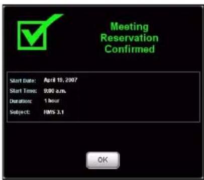
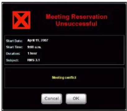
FIG. 166 Reservation Confirmed / Unsuccessful
4. Press OK.
Extending a Meeting At the Welcome panel
Within the Welcome page, press Extend Meeting. RMS extends the meeting in 15 minute increments. Both successful and failed extension attempts receive a message.
- Confirmed - the meeting has been extended.
● Unsuccessful - the meeting has not been extended.
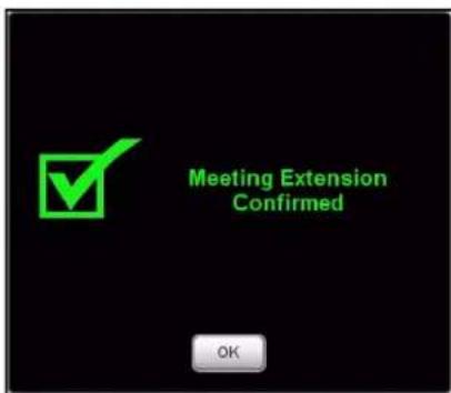
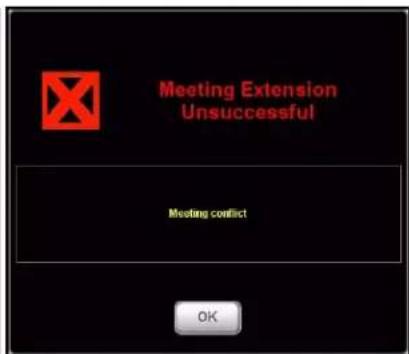
FIG. 167 Extension Confirmed / Unsuccessful
Ending a Meeting Early At the Welcome panel
- Within the Welcome page, press End Meeting. The Confirm Meeting End dialog box opens.
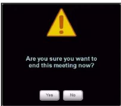
FIG. 168 Meeting End
-
press Yes. Based upon your scheduling system's support of this feature, you will see either:
-
Confirmed - the meeting has been ended.
● Unsuccessful - the meeting has not been ended.
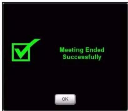
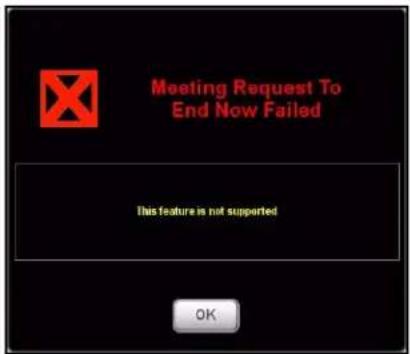
FIG. 169 Meeting End Confirmed / Unsuccessful
Ringing The Doorbell
Within the Welcome page, press Ring Doorbell. The Doorbell dialog on the In-room panel and a doorbell tone.
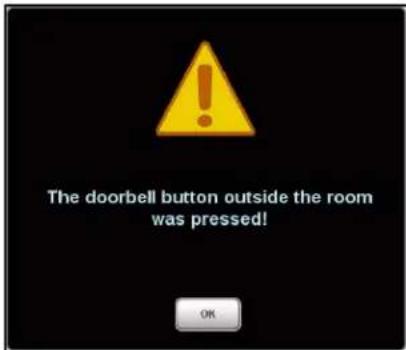
FIG. 170 Doorbell
The ring doorbell button will be hidden if the meeting room has enabled Do Not Disturb.
RMS In-Room Page
This page is displayed on the panel inside of the meeting room.
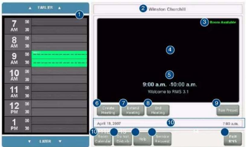
FIG. 171 RMS In-room Page
| RMS In-room Page | ||
| 1 | Meeting room schedule | The schedule for the meeting room. Navigate back and forward through the schedule using the EARLIER and LATER buttons at the top and bottom of the schedule.Select a reserved time to view its information. |
| 2 | Meeting room name The name of the meeting room. | |
| 3 | Meeting room status | The current status of the meeting room; Room Available or Room In Use. |
| 4 | Welcome image If configured, a welcome image appears in this space. | |
| 5 | Meeting information The time span and welcome text of a meeting selected in the meeting room schedule. | |
| 6 | Create Meeting When available, create a meeting and reserve the room. Selecting this button launches the RMS Meeting Request Dialog section on page 184. | |
| 7 | Extend Meeting When available, extends the reserve time for the meeting room. RMS extends in increments of 15 minutes. Reoccurring meetings cannot be extended. | |
| 8 | End Meeting Ends the meeting early and makes the room available to the schedule. Reoccurring meetings cannot end early. | |
| 9 | Run Preset If the meeting was created on the Scheduling page of RMS, the user had the option of creating a preset. The preset option allows you to execute it automatically or by this button. See the Creating an Appointment section on page 176. | |
| 10 | Date and time The current date and time. | |
| 11 | Room Calendar | Launches the calendar popup for the room schedule. Reservations for the selected room are displayed here. |
| 12 | Do Not Disturb | Selecting this button displays a "Do Not Disturb" dialog on the RMS Welcome Page section on page 183, and disables the doorbell feature. |
| 13 | Help | Launches the RMS Help Request dialog. You must establish who receives the request. |
| 14 | Service Request | Launches the RMS Service Request dialog. You must establish who receives the request. |
| 15 | Exit RMS | Exits the RMS panel pages. |
Finding a Meeting In a Room's Schedule
- Press the EARLIER and LATER buttons within the Meeting room schedule area.
- Once you have located the meeting, press the meeting to see more information.
Creating a Meeting At The In-Room Panel
- Within the In-room page, press Create Meeting. The RMS Meeting Request dialog box opens.
-
Set the following:
-
Start Date
- Subject
The Message field is not required for the scheduling troller but is a helpful field for users.
-
Press Reserve. You will then see one of the following:
-
Confirmed - the meeting has been created.
● Unsuccessful - the meeting has not been created.
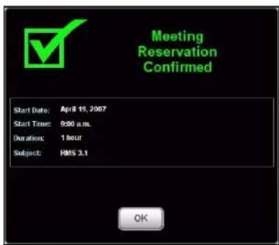
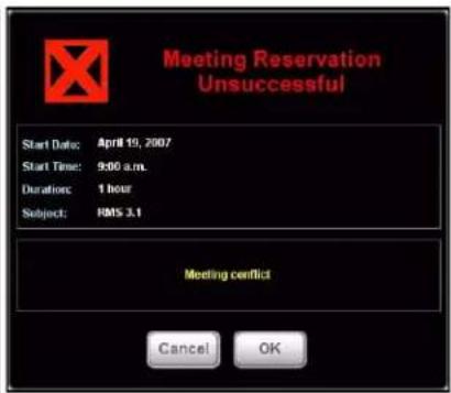
FIG. 172 Reservation Confirmed / Unsuccessful
4. Press OK.
Extending a Meeting At The In-Room Panel
Within the In-room page, press Extend Meeting. RMS extends the meeting in 15 minute increments. Both successful and failed extension attempts receive a message.
- Confirmed - the meeting has been extended.
● Unsuccessful - the meeting has not been extended.
FIG. 173 Extension Confirmed / Unsuccessful
Ending a Meeting Early At The In-Room Panel
- Within the In-room page, press End Meeting. The Confirm Meeting End dialog box opens.
FIG. 174 Meeting End
-
press Yes. Based upon your scheduling system's support of this feature, you will see either:
-
Confirmed - the meeting has been ended.
● Unsuccessful - the meeting has not been ended.
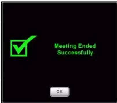
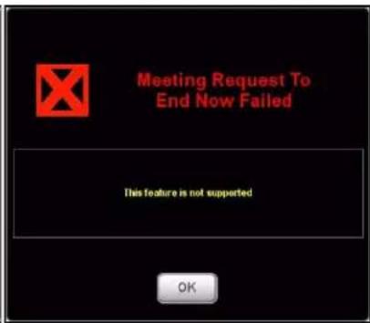
FIG. 175 Meeting End Confirmed / Unsuccessful
Executing a Meeting Preset
If a manually executed preset was created when the meeting was set, press Run Preset.
See Also...
- Creating an Appointment section on page 176.
- Creating a New Macro section on page 99.
Using the Room's Calendar
- Within the In-room page, press Room Calendar. The Room Calendar (FIG. 176) opens.
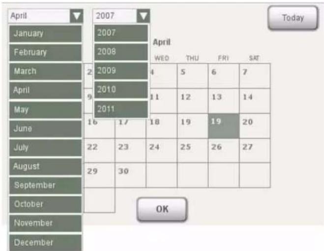
heatmap
| Month | April | February | January | | :--- | :--- | :--- | :--- | | January | 2007 | 2008 | 2007 | | February | 2008 | 2009 | 2007 | | March | 2009 | 2010 | 2007 | | April | 2010 | 2011 | 2007 | | May | 2011 | 2016 | 2007 | | June | 2011 | 2017 | 2007 | | July | 2011 | 2018 | 2007 | | August | 2011 | 2019 | 2007 | | September | 2011 | 2020 | 2007 | | October | 2011 | 2021 | 2007 | | November | 2011 | 2022 | 2007 | | December | 2011 | 2023 | 2007 | | April WED | 4 | 5 | 6 | | April FRI | 6 | 7 | 6 | | April SAT | 7 | 8 | 7 | | April WED THU FRI SAT | 11 | 12 | 13 | | April WED THU FRI SAT | 13 | 14 | 13 | | April WED THU FRI SAT | 19 | 20 | 19 | | April WED THU FRI SAT | 26 | 27 | 26 | | April WED THU FRI SAT | 27 | - | - | | April WED THU FRI SAT | - | - | - | | April WED THU FRI SAT | - | - | - | | April WED THU FRI SAT | - | - | - | | April WED THU FRI SAT | - | - | - | | April WED THU FRI SAT | - | - | - | | April WED THU FRI SAT | - | - | - | | April WED THU FRI SAT | - | - | 4 | | April WED THU FRI SAT | - | - | 5 | | April WED THU FRI SAT | - | - | 6 | | April WED THU FRI SAT | - | - | 7 | | April WED THU FRI SAT | - | - | 8 | | April WED THU FRI SAT | - | - | 9 | | April WED THU FRI SAT | - | - | 10 | | April WED THU FRI SAT | - | - | 11 | | April WED THU FRI SAT | - | - | 12 | | April WED THU FRI SAT | - | - | 13 | | April WED THU FRI SAT | - | - | 14 | | April WED THU FRI SAT | - | - | 15 | | April WED THU FRI SAT | - | - | 16 | | April WED THU FRI SAT | - | - | 17 | | April WED THU FRI SAT | - | - | 18 | | April WED THU FRI SAT | - | - | 19 | | April WED THU FRI SAT | - | - | 20 | | April WED THU FRI SAT | - | - | 21 | | April WED THU FRI SAT | - | - | 22 | | April WED THU FRI SAT | - | - | 23 | | April WED THU FRI SAT | - | - | 24 | | April WED THU FRI SAT | - | - | 25 | | April WED THU FRI SAT | - | - | 26 | | April WED THU FRI SAT | - | - | 27 | | April WED THU FRI SAT | - | - | 28 | | April WED THU FRI SAT | - | - | 29 | | April WED THU FRI SAT | - | - | 30 | | April WED THU FRI SAT | - | - | 31 | | April WED THU FRI SAT | - | - | 32 | | April WED THU FRI SAT | - | - | 33 | | April WED THU FRI SAT | - | - | 34 | | April WED THU FRI SAT | - | - | 35 | | April WED THU FRI SAT | - | - | 36 | | April WED THU FRI SAT | - | - | 37 | | April WED THU FRI SAT | - | - | 38 | | April WED THU FRI SAT | - | - | 39 | | April WED THU FRI SAT | - | - | 40 | | April WED THU FRI SAT | - | - | 41 | | April WED THU FRI SAT | - | - | 42 | | April WED THU FRI SAT | - | - | 43 | | April WED THU FRI SAT | - | - | 44 | | April WED THU FRI SAT | - | - | 45 | | April WED THU FRI SAT | - | - | 46 | | April WED THU FRI SAT | - | - | 47 | | April WED THU FRI SAT | - | - | 48 | | April WED THU FRI SAT | - | - | 49 | | April WED THU FRI SAT | - | - | 50 | | April WED THU FRI SATIFIG. 176 Room Calendar
- The first drop down menu allows you to change months. Press the current month to access other months.
- The second drop down menu allows you to change years. Press the current year to access other years.
- Press any day in the calendar to view information for that room on that day.
- You can return back to your current date at any time by pressing Today.
- Press OK when you are finished with the calendar.
Setting the Meeting To "Do Not Disturb"
Press the Do Not Disturb button to toggle the feature on and off. Enabling this feature places a dialog on the Welcome panel outside of the room and disables the doorbell.

FIG. 177 Do Not Disturb
Placing a Help Request
- Within the In-room page, press Help. The Help Request dialog box opens.
![Message To Send: Help Request 1 2 3 4 5 6 7 8 9 0 - = Back Clear q w e r t y u i o p [ ] \ Caps a s d f g h j k l : ' Enter Home Shift z x c y b n m . . / Shift ▲ End More Space Cancel Send](/content/2026/06/1185428/images/deb825a0db97567bb9d2ef6169a2cd1ae0c946cd50466445dbf1cd7fdcc4fda1.jpg)
FIG. 178 Help Request
-
Type your message using the on-screen keyboard.
-
Press Send. There are 2 responses you can expect from the Help Desk:
- Message from Help Desk
FIG. 179 Message from Help Desk
Press OK to confirm.
- Question from Help Desk Press your response to select.
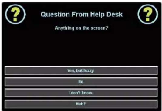
FIG. 180 Question from Help Desk
Placing a Service Request
- Within the In-room page, press Service. The Service Request dialog box opens.
![Message To Send: Service Request 1 2 3 4 5 6 7 8 9 0 - = Back Clear q w e r t y u i o p [ ] \ Caps a s d f g h j k l ; ' Enter Home Shift 2 x c v b n m . / Shift ▲ End More Space Cancel Send](/content/2026/06/1185428/images/cccaddca1ce56534936b483ef1f95d1ed99547b55cc3da5b24b277a5f4a8c86c.jpg)
FIG. 181 Service Request
- Type your message using the on-screen keyboard.
- Press Send; RMS will confirm with you that the request has been sent.
RMS Touch Panel Pages
AMX
It's Your World - Take Control™
- AMX Software License and Warranty Agreement
- Table of Contents
- RMS Resource Management Suite ....1
- Getting Started 13
- RMS Configuration Wizard 15
- Database Wizard 41
- RMS Web User Interface 51
- RMS Administration 53
- RMS Dashboard Page 55
- RMS Hotlist 57
- System Status Page 61
- Management Page 75
- Management - Internal Log Page.... 95
- Management - Control Functions Page.... 96
- Management - RFID Tags Page.... 101
- Reporting Page 103
- System Reports Page 103
- Room Reports 104
- Power Reports 118
- RMS Resource Management Suite
- Overview
- Additional Documentation
- What's New in RMS v3.3
- Windows 2008 Server
- System Requirements
- Minimum Hardware Requirements
- Supported Platforms
- RMS Supported Databases
- RMS Supported Scheduling and Mailbox Interfaces
- RMS Supported Web Browsers
- RMS SDK Support
- Additional System Requirements
- Windows 2008 Server - Required Features, Roles and Services
- Network Configuration
- RMS Application Install Checklist
- Installation
- The RMS SDK
- Upgrading to RMS v3.3 From RMS v3.x
- Upgrading to RMS v3.3 from RMS v2.2 Or Earlier
- Conceptualizing the RMS Application
- Licensing
- Licensing Summary
- Appointment Management Considerations
- Messaging and Notification
- Logging Configuration
- Security
- Windows Authentication
- ● Administrative Web Pages:
- - User Scheduling Web Pages:
- Enabling Integrated Windows Authentication
- Vertical Market Support
- Device Monitoring Framework
- Device Values
- Parameter Values
- Status Types
- Notification Process
- Alert Messages
- Advise Messages
- Scheduling System Plug-ins
- Getting Started
- Running the Configuration Wizard
- Adding NetLinx Systems As Rooms
- Adding And Configuring Groups
- Adding Users
- Adding Notifications
- Changing The Domain Path for Notifications
- RMS Configuration Wizard
- Appointment Management/Scheduling System
- Database
- Database - Connection
- Database - Configuration
- Database - Updates
- Product Selection
- Web Services
- Web Services - Microsoft IIS Server
- Web Services - Virtual Directory
- Services
- Services - Register
- Services - Start
- Licensing Summary - Asset Licenses vs. Scheduling License
- Licensing - Server Licenses
- Enter Server Serial Number
- Manual Authorization
- Manually Authorizing Your RMS Server
- Licensing - Client Licenses
- OS Permissions
- OS Permissions - Service User
- OS Permissions - Web User
- System Settings
- System Settings - NetLinx
- System Settings - Security
- System Settings - Administrator
- System Settings - Scheduling
- System Settings - Appointments
- System Settings - SMTP
- System Settings - SNPP
- System Settings - SNMP
- System Settings - RFID Tracking
- System Settings - Logging
- System Settings - Syslog
- System Settings - Reporting
- System Settings - Time Sync
- Name & Logo
- Creating A Custom Logo
- Finished
- Database Wizard
- Starting the Database Wizard
- Main Menu
- Convert RMS Database
- Apply RMS Update Script
- Configure Connection
- Create / Remove
- Create new database.
- Remove / Delete existing database.
- Import / Export
- Import to RMS database.
- Export Data from RMS database.
- Create A New Database
- Remove A Database
- Importing Data
- Exporting Data
- Converting A Database
- Applying Update Scripts
- Configuring Connection Settings
- Database Server:
- Database Name:
- RMS Web User Interface
- Sign in Page
- RMS Administration
- Administration Page
- RMS Dashboard Page
- How Do You Change Modes?
- Adding Contents
- Add Contents
- Restore Contents
- Imported Web Part Catalog
- Moving Columns
- Resetting the RMS Dashboard
- RMS Hotlist
- Unassigned NetLinx Systems
- See Also:
- Parameter Needing Attention
- Viewing a Room When Appearing In Parameter Needing Attention List
- Resetting a Room When Appearing In Parameter Needing Attention List
- Responding To a Room When Appearing In Parameter Needing Attention
- Room Troller Failure
- System Status Page
- Auto-Refresh
- Viewing System Status Information
- Viewing Device Information on the System Status Page
- View Devices Page
- Create Device Page
- Execute Control Function Page
- Device Information Page
- Modify Device Information Page
- Device Parameter Page
- Device Parameter History Page
- Modify Parameter Page
- Viewing Device parameters
- Viewing Device Parameter history
- Deleting Device Parameter history
- Modifying Device Parameters
- Deleting Device Parameters
- Viewing Detailed Device Information
- Modifying Device Information
- Moving a Device to a New Room
- Deleting Device Information
- Viewing a Device Log
- Executing a Device Control Function
- Management Page
- Management - Rooms Page
- Create New Group Page
- Creating a New Group
- Viewing Group Settings
- View Group Setting Page
- Editing a Group
- Deleting Groups
- Create New Room Page
- View Room Settings Page
- Viewing Room Settings
- See Also...
- Send Question Page
- Creating a New Room
- Editing a Room
- Deleting Rooms
- Sending a Question to a Room
- Management - Users Page
- Create New User Account Page
- Edit User Page
- Creating a New User
- Editing Users
- How Do I Disable/Enable A User?
- Deleting Users
- Management - Permissions Page
- Edit Role Page
- Creating a New Role
- Editing a Role
- Deleting a Role
- Management - Notifications Page
- Create New Notification Page
- Edit Notification Page
- Creating a Notification
- Editing a Notification
- Deleting a Notification
- Management - Systems Page
- View System Page
- Viewing a System
- Management - Devices Page
- Device Search Page
- Management - Internal Log Page
- Exporting an Internal Log
- Viewing Exported Internal Logs
- Deleting Exported Internal Logs
- Management - Control Functions Page
- Create Control Function Macro Page
- Edit Macro Page
- Schedule Macro Page
- Control Function Macro Schedules Page
- Creating a New Macro
- Viewing a Macro
- Executing a Macro
- Deleting a Macro
- Scheduling a Macro
- Viewing a Macro Schedule
- Management - RFID Tags Page
- Tag Details Page
- Assign Tag to Device Page
- Reporting Page
- System Reports Page
- Room Reports
- System Reports - Help Requests
- System Reports - Help Requests Results
- System Reports - Help Requests (Detailed)
- System Reports - Help Requests (Detailed) Results
- System Reports - Residence Usage
- System Reports - Residence Usage Results
- System Reports - Source Usage
- System Reports - Source Usage Results
- System Reports - Cumulative Lamp Hours
- System Reports - Cumulative Lamp Hours Results
- System Reports - Transport Run Time
- System Reports - Transport Run Time Results
- System Reports - Current Source Usage
- System Reports - Current Source Usage Results
- System Reports - Current Lamp Hour
- System Reports - Current Lamp Hours Results
- Power Reports
- Power Reports - System Power
- Power Reports - System Power Results
- Power Reports - Device Power
- Power Reports - Device Power Results
- Power Reports - System Power (Detailed)
- Power Reports - System Power (Detailed) Results
- Quality of Service Reports
- Quality of Service Reports - System Online
- Quality of Service Reports - System Online Results
- Quality of Service Reports - Device Online
- Quality of Service Reports - Device Online Results
- Quality of Service Reports - Device Communications
- Quality of Service Reports - Device Communications Results
- Quality of Service Reports - Device Control Failures
- Quality of Service Reports - Device Control Failures Results
- Scheduler Reports
- Scheduler Reports - Help Requests
- Scheduler Reports - Help Requests Results
- Scheduler Reports - Help Requests (Detailed)
- Scheduler Reports - Help Requests (Detailed) Results
- Scheduler Reports - Room Usage
- Scheduler Reports - Room Usage Results
- Scheduler Reports - Source Usage Results
- Running a System Report
- Tracking Reports
- Tracking Reports - Device Activity
- Tracking Reports - Device Activity Results
- Tracking Reports - Device Activity (Detailed)
- Tracking Reports - Device Activity (Detailed) Results
- Tracking Reports - Room Activity
- Tracking Reports - Device Location
- Tracking Reports - Device Location Results
- Tracking Reports - Device Battery Levels
- Tracking Reports - Device Battery Levels Results
- Administrative Reports
- Administrative Reports - Device Inventory
- Administrative Reports - Device Inventory Results (Cont.)
- Administrative Reports - Control System Inventory
- Administrative Reports - Control System Inventory Results
- Administrative Reports - System Users
- Administrative Reports - System Users Results
- Internal Log Report Page
- Internal Log Entry Page
- Viewing Log Entries
- Adding Notes To Log Entries
- Deleting Log Entries
- Source Usage Page
- Viewing Source Usage Reports
- Lamp Hours Report Page
- Viewing Lamp Hours Reports
- Configuration Page
- Appointment Settings Page
- Configuring The System Storage Settings
- Setting the Appointment Master Password
- Configure Internal Log Page
- Configuring the Internal Log
- Enabling/Disabling Internal Log
- Purging the Internal Log
- Configure Notification Template Page
- Create New Template Page
- Viewing a Notification Template
- Creating a new Notification Template
- Deleting a Notification Template
- Copying a Notification Template
- Prestige Levels Page
- Editing Prestige Levels
- Enabling/Disabling Prestige Levels
- System Licensing Page
- Checking Client Licensing Information
- Adding a Client License
- Removing a Client License
- Hotlist Settings Page
- Creating a New Help Response
- Editing a Help Response
- Deleting a Help Response
- Help Page
- About RMS Application Page
- Administrator's Guide
- User's Guide
- Version Information Page
- View Readme
- System Diagnostics
- Status Page
- Checking System Status
- Connections Page
- Checking RMS connections
- Restarting Connection Server
- Resources Page
- Displaying/Hiding Resource Keys
- Appending Culture Codes to Strings
- Displaying the Resource Lookup Table
- Debugging Page
- Setting Debug Options And Debugging The RMS Server
- Sitemap Page
- RMS Scheduling Page
- View Schedule Page
- Day View Page
- Opening Day View
- Week View Page
- Opening Week View
- Month View Page
- Opening Month View
- Add Appointment Page
- Appointment Details Page
- Creating an Appointment
- Creating an Appointment with an External Scheduler
- Room Search Page
- Room Search Results Page
- Conducting a Room Search
- RMS User Page
- How Do I Sign In To RMS?
- Preferences Page
- Setting the Default Language
- Setting the Home Page
- Resetting Column Sorting
- Setting Scheduling View Hours
- User Profile Page
- Editing Your User Profile
- Changing Your User Password
- Setting User Notification Time Span
- User Notifications Page
- Creating new User Notifications
- Sign Out Page
- Signing Out of RMS
- RMS Touch Panel Pages
- RMS Welcome Page
- RMS Meeting Request Dialog
- Finding a Meeting In a Room's Schedule
- Creating a Meeting At The Welcome Panel
- Press OK.
- Extending a Meeting At the Welcome panel
- Ending a Meeting Early At the Welcome panel
- Ringing The Doorbell
- RMS In-Room Page
- Creating a Meeting At The In-Room Panel
- Extending a Meeting At The In-Room Panel
- Ending a Meeting Early At The In-Room Panel
- Executing a Meeting Preset
- Using the Room's Calendar
- Setting the Meeting To "Do Not Disturb"
- Placing a Help Request
- Placing a Service Request
Brand : AMX
Model : RMS Interface for Lotus
Category : Software