ENVS800 - Surveillance Camera EverFocus - Free user manual and instructions
Find the device manual for free ENVS800 EverFocus in PDF.

User questions about ENVS800 EverFocus
0 question about this device. Answer the ones you know or ask your own.
Ask a new question about this device
Download the instructions for your Surveillance Camera in PDF format for free! Find your manual ENVS800 - EverFocus and take your electronic device back in hand. On this page are published all the documents necessary for the use of your device. ENVS800 by EverFocus.
USER MANUAL ENVS800 EverFocus
Installation & Operation Manual

natural_image
Exterior view of a EverFocus air conditioner unit (no visible text or symbols on body)ENVS800 / ENVS1600 / ENVS3200
Nevio Network Video Servers
Safety Precautions
To avoid any damage, please consider the following safety warnings:
- Never place the recorder near heaters, furnaces, other heat sources or in direct sunlight.
- Operate the device only in locations maintaining the specified operating temperature range 0^ 40^ / 32^ +104^ , with moderate relative humidity.
- Make sure that the device's ventilation slots are not covered or obstructed.
- For cleaning, make sure the device is unplugged and only use a damp cloth without caustic detergents.
- Install the device only in dry and dustproof surroundings. Protect the device against any possible leaks or spills.
- Do not insert or allow anything to fall into the enclosure through the ventilation slots.
- Do not attempt to disassemble the NVR. To prevent electric shock, do not remove screws or covers. Contact qualified service personnel for maintenance. Handle the NVR with care. Do not strike or shake, as this may damage the NVR.
- Do not operate the NVR with other than specified power supplies. The input power source of the power supply is \~115 VAC/\~230 (switchable).
- Choose an installation location for the NVR where it will not be subjected to mechanical shock or vibration.
- Avoid disconnecting the power cable during operation, or otherwise turning off the power abruptly; use the orderly shutdown methods for MS Windows.

ATTENTION! This is a class A product which may cause radio interference in a domestic environment; in this case, the user may be urged to take adequate measures.

Federal Communication Commission Interference Statement
This equipment has been tested and found to comply with the limits for a Class B digital device, pursuant to Part 15 of the FCC Rules. These limits are designed to provide reasonable protection against harmful interference in a residential installation. This equipment generates, uses and can radiate radio frequency energy and, if not installed and used in accordance with the instructions, may cause harmful interference to radio communications. However, there is no guarantee that interference will not occur in a particular installation. If this equipment does cause harmful interference to radio or television reception, which can be determined by turning the equipment off and on, the user is encouraged to try to correct the interference by one of the following measures:
•Reorient or relocate the receiving antenna.
- Increase the separation between the equipment and receiver.
- Connect the equipment into an outlet on a circuit different from that to which the receiver is connected.
- Consult the dealer or an experienced radio/TV technician for help.
FCC Caution: Any changes or modifications not expressly approved by the party responsible for compliance could void the users' authority to operate this equipment.

This Product is RoHS compliant.
WEEE

Your EverFocus product is designed and manufactured with high quality materials and components which can be recycled and reused.
This symbol means that electrical and electronic equipment, at their end-of-life, should be disposed of separately from your household waste.
Please, dispose of this equipment at your local community waste collection/recycling centre. In the European Union there are separate collection systems for used electrical and electronic product. Please, help us to conserve the environment we live in!
The information in this manual was current upon publication. The manufacturer reserves the right to revise and improve his products. Therefore, all specifications are subject to change without prior notice. The manufacturer is not responsible for misprints or typographical errors.
Please read this manual carefully before installing and using this unit. Be sure to keep it handy for later reference.
CONTENT
1 INTRODUCTION....6
2 MAIN FEATURES....6
3 SPECIFICATIONS 6
3.1 T ECHNICAL DATA....6
3.2 S UPPORTED CAMERA MODELS....8
3.3 D IMENSIONS 9
3.4 D ELIVERY SCOPE 9
4 HARDWARE INSTALLATION....11
4.1 F RONT PANEL CONTROLS AND CONNECTORS 11
4.2 B ACK PANEL CONNECTORS.... 11
4.3 S TATUS LED GIGABIT LAN PORT 12
4.4 SYSTEM CONNECTIONS....12
5 SYSTEM SETUP....13
5.1 F FIRST TIME SYSTEM START 13
5.2 M AIN CONSOLE SCREEN CONTROLS....13
5.3 Q QUICK START SETUP....14
5.4 D ETAILED SETUP 22
5.4.1 Setting - General 22
5.4.2 Setting - Camera 24
5.4.3 Setting - I/O Device 30
5.4.4 Setting - PTZ - Config 31
5.4.5 Setting - Hotline (communication settings) 32
5.4.6 Setting - User Account 33
5.4.7 Setting - Address book 34
5.4.8 Setting - Monitor display 35
5.4.9 Setting - Joystick 36
5.7 E-M AP 61
5.8 COUNTING APPLICATION 63
5.9 N ETWORK SERVICES 66
5.9.1 Network service: Live Streaming....66
5.9.2 Network Service: Remote Playback....699
5.9.3 Network Service: 3GPP Service 73
5.9.4 Network Service: Remote Desktop 74
5.9.5 Network Service: Central Management 75
6 APPENDIX A: DB TOOL 76
6.1 R EPAIR DATABASE....77
6.2 E XPORT CONFIGURATIONS 80
7 APPENDIX B: 3 GPP SETUP EXAMPLES ....81
7.1 C ONFIGURATION IN NVR 81
7.2 C ONFIGURATION MOBILE PHONE....82
7.2.1 BenQ-Siemens E81 82
7.2.2 BenQ P50 84
8 APPENDIX C: INSTALLATION REMOTE DESKTOP TOOL....87
9 APPENDIX D: ONLINE LICENSE PROCEDURES....87
• 9.1 Overview....87
• 9.2 Rationale....88
• 9.3 Activation....88
o 9.3.1 Activate by inputting serial number (SN)....88
- 9.3.2 Activate by importing serial number (SN) files (txt format)....94
■ 9.3.2.1 Online....94
■ 9.3.2.2 Offline....95
- 9.3.3 Activate from dongle....100
■ 9.3.3.1 Online....100
■ 9.3.3.2 Offline....102
• 9.4 Transfer (De-activation)....107
o 9.4.1 Online transfer....107
- 9.4.2 Offline transfer....108
- 9.5 The states of a serial number....112
• 9.6 FAQ....112
9.6.1 How do I add more channels to the current license I am using?......112
9.6.2 What if I lose my serial numbers?......113
9.6.3 What if someone uses my serial numbers?......113
- 9.6.4 How do I activate in a closed system without internet access?......113
1 Introduction
The NEVIO NVR network video recorders are designed for recording and managing IP video devices. Easy and intuitive operation, combined with intelligent search functions enable fast and efficient evaluation of video records. Compatibility with many IP cameras from many different manufacturers allows the installation of this NVR series in a wide range of security applications.
2 Main Features
- Management of 32 or more channels from Megapixel cameras, IP cameras and video servers
- Multi-brand IP product support
- Local and remote PTZ control
- Digital PTZ
- Bidirectional audio
• I/O control of IP-Video devices - Multi-Language support
- Dual monitor support
- Integrated video analytics
- Integrated counting application
- System and event log database
• Support for EKB-200 USB Joystick
• 3GPP live view support - Easy installation with automatic camera search
3 Specifications
3.1 Technical data
| Physical | |||
| ENVS800 ENVS1600 ENVS3200 | |||
| IP Video Cannel | 8 16 32 | ||
| Recording/Playback Rate | Up to 30 FPS / channel | ||
| Total Recording Rate | Up to 960 FPS | ||
| (depending on camera type / compression settings / method) | |||
| View Mode | 1/4/6/9/10/13/16/25/36 | ||
| Compression Method Supported | H.264 / MJPEG / MPEG4 | ||
| Audio | Bidirectional transmission, 1 audio channel per video channel (depending on specification of IP - device) | ||
| Video Storage (excludes O/S and system software on HDD 1) | 2TB 2TB 4TB | ||
| Internal HDD | Up to 3 x 3.5" HDD (1 system drive, 2 recording drives) | ||
| Video Export | USB 2.0 interface or to network drive | ||
| Network Interface | 1 Gbit/s, RJ45, IEEE 802.3 | ||
| Other Interfaces | USB2.0 6 x, PS2 keyboard/mouse. Optional EKB200 Joystick | ||
| Alarm I/O Support of I/O contacts of connected IP devices (depending on specification of IP - device) | |||
| Monitor Output | 1 x VGA out, 1 x DVI out, 1xHDMI out - Triple monitor support | ||
| Power | 115/230 (switchable) VAC, 300 VA max. | ||
| Ambient Temperature | 0°C ~ +40°C | ||
| Housing | Low profile PC type | ||
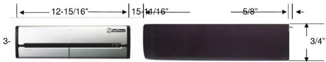
| Dimension (W x H x D) | 328.6 x 85.73 x 4.4.34 mm / 12-15/16" x 3-3/4" H x 16-5/16" | ||
| Weight | 6.8 kg / 15 lbs (NVR08S) | ||
| Functionality | |||
| General / System | |||
| Menu Language Support Danish, English, German, Finnish, French, Greek, Italian, Japanese, Korean, Portuguese, Russian, Slovakian, Spanish, Thai, Czech, Turkish, Hungarian, Chinese | |||
| E-Map Unlimited number of maps or other graphics with free placement of camera or I/O icons | |||
| Monitor Output Triple monitor support: up to two independent monitors for Live view; third monitor for dedicated Playback view; or, if less than 3 monitors, Playback screen can launch on same monitor as Live View screen. | |||
| Bandwidth Monitor Optional OSD display of individual network bandwidth per camera and total streaming bandwidth | |||
| Database Management Integrated database management tool for reconstructing, repairing or relocating database and export option for configuration file | |||
| Live View | |||
| Video Analytic General motion, missing object, camera occlusion, foreign object, loss of focus, signal lost; each alarm can trigger up to 10 different event reactions | |||
| PTZ PTZ control in OSD or with EKB200 Joystick for PTZ cameras; Digital software PTZ for all cameras | |||
| Recording | |||
| Recording Method | Continuous, schedule, event (motion / contact) | ||
| Schedule | Individual for each camera, daily schedule with 6 possible recording modes | ||
| Recording Rate | 1~30 FPS adjustable for each camera (depending on camera capabilities) | ||
| Playback | |||
| Multi-channel Playback | Up to 16 channels time synchronized | ||
| Search Function Time / Date via calendar and time bar; intelligent search with modes general motion, missing object, camera occlusion, foreign object, signal lost | |||
| Video Enhancement | Saturation, contrast, brightness, sharpness | ||
| Video Export | Snapshot in JPEG format, video export in AVI or ASF format | ||
| Video Backup Backup of multiple camera video data to local / network video drive or external CD/DVD | |||
| Remote Access | |||
| Remote Video Access Method | Remote client software live view (up to 2 windows/monitors with up to 16 x view each at 1 PC)Remote client software playback view (up to 16 x view) with remote backup function (multiple channel backup up to 16 channels)Web browser view (live / playback with up to 16 x view),Mobile phone client ("3G"/rtsp - streaming support required);no limit for number of installations for all remote applications | ||
| Max. Number of Remote Video Channel Access | 128 video channels total | ||
| Remote Maintenance Remote desk | ktop viewer allows complete network access to ENVS Server (1 monitor display only supported) including configuration | ||
3.2 Supported Camera Models
| Supported IP Cameras / Video server Status: Version 3.3.6.1 / August 2010 | |
| Manufacturer | Supported Products |
| EverFocus | EAN800A; EAN800AW; EAN850A; EAN900; EDN800; EDN850H; EZN850; EVS100; EVS200A; EVS200AW; EVS400; EAN750; FPN2700; FPN3100; FPN3600 |
| ACTI | SED 2100; SED 2120; SED 2140; SED 2310Q; SED 2320Q; SED 2400; SED 2420; SED 2600; SED 2610; SEM 1110; CAM 5130; CAM 5140; CAM 5150; CAM 5200; CAM 5201; CAM 5221; CAM 5300; CAM 5301; CAM 5321; CAM 5500; CAM 6100; CAM 6200; CAM 6220; CAM 6500; CAM 6510; CAM 6520; CAM 6600; CAM 6610; CAM 6620; CAM 6630; CAM 7100; CAM 7120; CAM 7200; CAM 7220; CAM 7300; CAM 7301; CAM 7320; CAM 7321; CAM 7322; ACD 2000Q; ACD 2100; ACD 2200; ACD 2300; ACD 2400; ACM 1011; ACM 1231; ACM 1232; ACM 1311; ACM 1431; ACM 1432; ACM 1511; ACM 3001; ACM 3011; ACM 3211; ACM 3311; ACM 3401; ACM 3411; ACM 3511; ACM 3601; ACM 3603; ACVM 3701; ACM 3703; ACM 4000; ACM 4001; ACM 4100; ACM 4200; ACM4201; ACM 4200; ACM 4210; ACM 5001; ACM 5601; ACM 5611; ACM 5711; ACM 7411; ACM 8201; ACM 8211; ACM 8511; AMU-9410; AMU-9711; TCM 4301*; TCM 5311*; TMU-9811; TMU-9911; TCM 5312; TCM 5601; TCM 5611; TCM 7411; TCM 3511; TCM 1511; TCM 1231; TCM 1232; TCM 4101; TCD 2500; |
| Arecont Vision | AV1300; AV1305*; AV1310; AV1335; AV2000; AV2100; AV2105*; AV2110; AV2155*; AV3100; AV3105*; AV3110; AV3130; AV3135; AV5100; AV5105*; AV5110; AV5155; AV8180; AV8185; AV8360; AV8365; AV10005M |
| Atlantis Land | A02-OIPCAM1; A02-OIPCAM2; A02-OIPCAM3; A02-IPCAM5; A02-IPCAM6; A02-IPCAM7; A02-IPCAM8; A02-IPCAM9; A02-IPCAM10; A02-IPCAM11; A02-IPCAM12; A02-IPCAM13; A02-IPCAM14; A02-IPCAM15; A02-IPCAM16; A02-IPCAM17 |
| Axis | 205; 206; 206M; 206W; 207; 207W; 207MW; 209FD; 209FD-R; 209MFD; 209MFD-R; 210; 210A; 211; 211A; 211M; 211W; 212; 213; 214; 215; 216FD; 216FD-V; 216MFD; 216MFD-V; 221; 223M; 225FD; 231D; 231D+; 232D; 232D+; 233D; 240Q; 240Q; 241Q; 241QA; 241S; 241SA; 242S; 243Q; 243SA; 247S; 2460; M1011*; M1011-W*; M1031-W*; M1054; M1103; M1104; M1114; M3011; M1113; M3014; M3203/M3; M3204/M3; M7001; P1311; P1343; P1344; P1346; P3301*; P3301-V*; P3304; P3343; P3343-V; P3343-VE; P3344; P3344-V; P3344-VE; P5534; Q1755*; Q1910; Q1910-E; Q6032-E; Q6034; Q7401*; Q7404; Q7406 |
| Basler | BIP-640C; BIP -640CDN; BIP -1000C; BIP-1000CDN; BIP-1300C; BIP-1300CDN; BIP-1600C; BIP-1600CDN |
| Bosch | NW-455 |
| Brickcom | WCB-100A; WFB-100A; FD-100A |
| Cisco | PVC300; WVC210 |
| CNB Technology | IBE3815NVR; IBE3815PVR; IBE5810CR; IBE5810PCR; IDP4000VD; IDP4000VR; IDP4030VR; IGP1000; IGP1030; IJB2000; INS2000; IPM3063N; IPM3063P; ISMC1063N; ISMC1063P; ISS2765NW; ISS2765PW; IVP4000VR; IVP4030VR; IDC4000T; IVC4000T |
| Digimerge | DNS1010; DND7100E |
| D-Link | DCS-6620; DCS-6620G; DCS-6111; DCS-6110; DCS-5610; DCS-5300; DCS-5300G; DCS-5220; DCS-5300; DCS-5300G; DCS-3420; DCS-3415; DCS-3410; DCS-3220; DCS-3220G; DCS-3110; DCS-2120; DCS-2100; DCS-2100G; DVS-104; DVS-301; DCS-900; DCS-G900; DCS-910; DCS-920; DCS-950; DCS-950G; DCS-3110; DCS-3410; DCS-3415; DCS-5220(TW); DCS-5610; DCS-6110; DCS-6111; |
| Dynacolor | nZH06X; nZH10X; nZH21X; nNH221; Nnh061; V1 indoor; V1 outdoor; V6 |
| eneo | GLC-1401; GLC-1601; GLC-1602II; GLD-1401; GLD-1501; GLS-2101 |
| Etrovision | EV3130AW; EV3130A; EV3131; EV3830H/HP; EV6130W; EV6130P; EV6131HW; EV6131H/HP; EV6132A; EV6230A; EV6332; EV6333A; EV6530; EV6531A; EV6532A |
| Eyewiew | IPS-900NIC |
| Fine | TCP-690; TCP-690DN; TCP-HP930; WB-8211SD; WB-8411; CDV-3V930; TCP-690U; TCP-HP930U; WB-8211SDU; CDV-3V930U; EP-936; EP-908; EP-601; EP-201; EP-221; EP-221DN; MD-D1200; TCP670DNU; TCP680DNU |
| HIKVision | DS-2DF1; DS2CD852MFE; DS2CD802PF; DS2CD802NF; DS2CD812PF; DS2CD812NF; DS2CD832PF; DS2CD832NF; DS2CD892PF; DS2CD802PFE; DS2CD802NFE; DS2CD812NFE; DS2CD812NFE; DS2CD832PFE; DS2CD832NFE; DS2CD892PFE; DS2CD892NFE; DS2CD812PFIR1; DS2CD812NFIR1; DS2CD832PFIR1; DS2CD832NFIR1; DS2CD892PFIR1; DS2CD892NFIR1; DS2CD812NFIR3; DS2CD832PFIR3; DS2CD832NFIR3; DS2CD892PFIR3; DS2CD702PF; DS2CD712PF; DS2CD712NF; DS2CD732PF; DS2CD732NF; DS2CD792NF; DS2CD702PFB; DS2CD702NFIB; DS2CD712PFB; DS2CD712NFB; DS2CD732PFB; DS2CD732NFB; DS2CD792NFB; DS2CD792PFEB; DS2CD792NFEB; DS6101HFI-IOP; DS2CD852MFE; DS2CD752MFE; DS2CD752MFFB; DS2CD752MFFH; DS2CD862MFE; DS2CD762MF; DS2CD762MFFF; DS2CD762MFFII; DS2CD762MFFB(II); DS2CD812P(N)-IR5; DS2CD832P(N)-IR5; DS2CD892P(N)-IR5; DS2CD852F; DS2CD752F-E |
| Hitron | HNCB-EJSN; HNG-EISAW054; HWD125MN; HECMC4V0C4 |
| IcanTek | ICanView220; ICanView222; ICanView230; ICanView232; ICanView240; ICanView250; ICanView260; ICanView270; ICanView280; ICanView290; ICanserver510; iCanView362MP; iCanView332MP; iCanView3650MP; ICanserver612 |
| IQinVision | IQ040S; IQ041S; IQ042S; IQ040S; IQD41S; IQD42S; IQ540S; IQ541S; IQ542S; IQD30S; IQD31S; IQA25S; IQcyc301; IQcyc301m; IQcyc301w; IQcyc302; IQcyc302w; IQcyc303; IQcyc303w; IQcyc501; IQcyc510; IQcyc511; IQeey601; IQeey602; IQeey603; IQeey701; IQeey702; IQeey703; IQeey705; IQeey751; IQeey752; IQeey753; IQeey755; IQeey855 |
| JVC | VN-C20U; VN-E4(U); VN-C205U; VN-C215U; VN-C655U; |
| LevelOne | FCS-0010; FCS-0020; FCS-0030; FCS-1010; FCS-1030 V1.0; FCS-1030 V2.0; FCS-1040; FCS-1040-V3.0; FCS-1050; FCS-1060; FCS-1070; FCS-1081; FCS-1081A; FCS-1091; FCS-1101; FCS-1121; FCS-1131; FCS-1141; FCS-1151; FCS-3000; FCS-3021; FCS-3031; FCS-3051; FCS-3061; FCS-3071; FCS-4010; FCS-4020; FCS-4x00; FCS-5011; FCS-5030; FCS-7011; FCS-7111; WCS-0010; WCS-0020; WCS-0030; WCS-1090; WCS-2060; WCS-2010 V1.0; WCS-2010 V2.0; WCS-2030 V1.0; WCS-2030 V2.0; WCS-2030 V3.0; WCS-2040; WCS2040-V3.0; WCS-2070 |
| Linksys | PVC2300; WVC2300; WVC210 |
| Lorex | LNE3003 |
| Lumenera | lc045c; lc045c-dn; lc075c; lc075c-dn; lc165c; lc165c-dn; lc175c; lc175c-dn; lc259c; lc275c; lc275c-dn; lc375c; lc375c-dn; lc11059c; Li165C |
| Robotix | D12D-IT; D12D-Sec; D2M-Basic; D22M-IT; D22M-Sec; M10D; M12D-IT; M12D-Sec; M12D-Web; M22M-IT; M22M-Sec; Q22M-Basic; Q22M-Sec; Q24-Basic; Q24-Sec; D24M-Basic; D24M-IT; D24M-Sec |
| Moxa | Vport 25; Vport 251; Vport 254; Vport 351 |
| Panasonic | BB-HCM100; BB-HCM110; BB-HCM311; BB-HCM331; BB-HCM371; BB-HCM381; BB-HCM403; BB-HCE481; BB-HCS301; BB-HCM-547; BB-HCM511; BB-HCM515; BB-HCM527; BB-HCM531; BB-HCM580; BB-HCM581; BB-HCM701; BB-HCM705; BB-HCM715A; BB-HCM735A; BL-C10; BL-C1; BL-C20; BL-C30; BL-C101A; BL-C111; BL-C121A; BL-C131; BL-C140A; BL-C160; KX-HCM110; KX-HCM280A; WJ-NT304; WJ-NT314; WV-NP1000; WV-NP1004; WV-NM100; WV-NP240; WV-NP244; WV-NP304; WV-NP472; WV-NP502; WV-NS202; WV-NS202A; WV-NS324; WV-NW484; WV-NS954; WV-NS950; WV-NW964; WV-NW484; WV-NW502S; VW-NW960; WV-NW964; DG-NF284; DG-NF302; DG-NP240; DG-NP244; DG-NP304; DG-NS202; DG-NS202A; DG-NS950; DG-NS954; DG-NW960; DG-NW964; WJ-NT304; WJ-NT314; WV-NF-284; WV-NF302; |
| Pixord | 100; 120/126/128; 200/206; 201; 205; 207; 240; 241; 261; 262; 263; 300; 400/42X; 461; 463; 1000; 1401; 2000; 4000; 405; 410; 405M; 411/412; 415M; 416 |
| Planet | ICA-510; ICA-700; ICA-151W; ICA-151; ICA-750; ICA-107W; ICA-107P; ICA-107; ICA-108; ICA-108W; ICA-120; ICA-230; ICA-230W; ICA-230P; ICA-M230; ICA-310; ICA-310W; ICA-312; ICA-312v2; ICA-350; ICA-350-V2; ICA-501; ICA-525; ICA-530; ICA-651; ICA-601; IVS-110 |
| Samsung Electronics | SCC-6475; SNC-B2315; SNC-B5395; SNC-B2331; SNC-B2335; SNC-B5386; SNC-B5399; SNC-C6225; SNC-C7225; SNC-C7478; SNC-M300; SNP-3300A; SNB-2000; SNB-3000; SND-3080; SNV-3080 |
| Santec | SNC390DN/W; SNC512IR/W; SNC565IR/W; SNC620/W; SNC670IR/W; SNC5211MIR; SNC6201M; SNC3901MDN;SNCP3601M |
| Sanyo | VCC-IIDN1; VCC-IID2500; VCC-IID5200P; VCC-IID3500; VCC-IID3500P; VCC-IID2100; VCC-IID2100P; VCC-HD2300; VCC-HD2300P; VCC-HD3100; VCC-HD3100P; VCC-HD3300; VCC-HD3300P; VCC-HD4600; VCC-HD4600P; VCC-HD5400; VCC-HD5400P; VCC-HD5600; VCC-HD5600P; VDC-9585P; VDC-9584N; VCC-9800P; VCC-9800NA;VCC-ZM600N |
| Seorim | SVC-303041NR-DN; SVG-3110; SVG-3410; SVD-3020-PTZ; SVD-302x; |
| StarDot | SD-130; D-300; SD-500; SDEXP4; SDEXP2; SDH130B; SDH130V; SDH130VN; SDH300B;SDH300V; SDH500B;SDH500BN; SDH500V; SDH500VN; |
| Sony | SNC-CM120; SNC-CS10; SNC-CS11; SNC-CS20; SNC-CS3; SNC-CS50; SNC-DF40; SNC-DF50; DF70; SNC-DF80; SNC-DF85; SNC-DM110; SNC-DM160; SNC-DS10; SNC-DS60; SNC-P1; SNC-P5; SNC-RX530; SNC-RX550; SNC-RX570; SNC-RZ25; SNC-RZ30; SNC-RZ50; SNT-V704; SNT-EX104; SNC-DH180; SNC-RH124; SNC-CH140; SNC-CH180; SNC-CH240; SNC-DH140; SNC-DH240; SNC-RH164; SNC-RS36P; SNTEX154; SNT-EX101E; SNT-EP154 |
| Toshiba | IK-WB02A; IK-WR01A; IK-WB21A; IK-WB15A; IKWB70A; IKWD01A |
| Truen | TCS-200; TCAM-230; TCAM-250; TCAM-251; TCAM-270L; TCAM-270M; TCAM270II |
| Vivotek | FD61x1; FD61x2; FD7130; FD7131; FD7132; FD7141; FD7160; IP21x1; IP21x2; IP3132; IP3133; IP3135; IP3135PLNK; IP3136; IP3136PLNK; IP3137; IP31x1; IP31x1TLFN; IP31x2; IP31x7; IP52x2; IP51x4; IP6114; IP6124; IP61x2; IP61x4; IP61x7; IP7130; IP7131; IP7132; IP7133; IP7134; IP7135; IP7137; IP7138; IP7139; IP7142; IP7151; IP7152; IP7153; IP7154; IP7160; IP7161; IP71x7; IP7251; IP7330; IP7361; IX7151; PT3134; PT31x2; PT31x7;PT7000; PT7135; PT7137; PZ61x2; PZ7131; PZ7151; PZ7152; PZ71x1; PZ71x2; SD61x2; SD7151; SD73x3; TC5330; TC5331; VS2101; VS2401; VS2402; VS2403; VS3100; VS3101; VS3102; VS3102XLTH; VS7100; IP8161; VS8102; FD8161; FD8361 |
| Y-cam | Black; White; Knight |
| Zavio | B5110; B6110; D510E; D520E; D610A; D6111; D611E; F210A; F3100; F3105; F312A;F5100; F5105; F510E; F510W; F5110 ;F5115; F511E; F511W; F520E; F521E; F531E; F610A; F611E; F721A; F731E; M510E; M510W; M511E; M511W; P5110; P5115; V111T |
3.3 Dimensions
3.4 Delivery scope
• ENVS Server PC
- Keyboard
- Mouse
- Power Cord
- Software Licence S/N Document
- NVR software installation package. Located on the PC desktop under folder \EverFocus NVR, if needed to modify/repair the NVR software
• Installation and Operation Manual PDF on PC desktop
• This Quick Start Guide
• Genuine Windows OS CD-ROM
• Genuine Windows Label with Product Key (on PC).
4 Hardware installation
4.1. Front panel controls and connectors
![EverFocus DL DVD Burner behind panel Power switch Reset button Power LED HDD LED USB Ports [4] Audio [Microphone, speaker]](/content/2026/06/1184203/images/ab089e3da18c688c2f73348aa8429d2d8c28beafd62b7691fc0504509fd2f405.jpg)
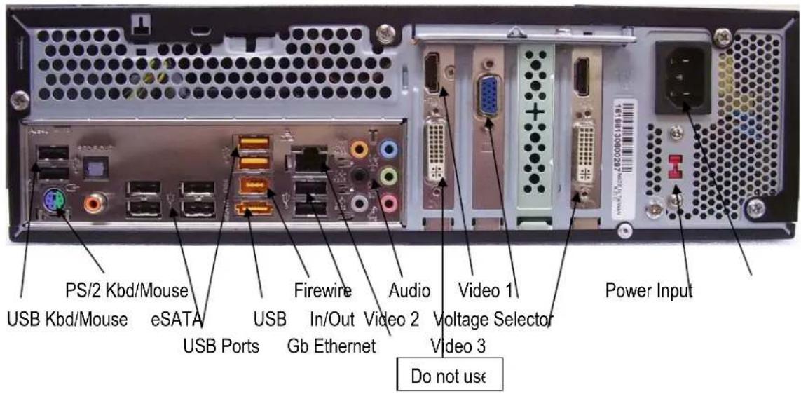
4.2. Back panel connectors
4.3 Status LED Gigabit LAN port
The LAN RJ45 socket has 2 integrated LED for status of the LAN connectivity:
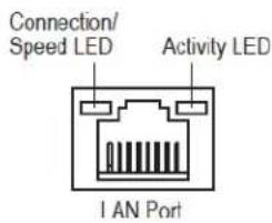
Connection/Speed LED:
| State | Description |
| Orange | 1 Gbps data rate |
| Green | 100 Mbps data rate |
| Off | 10 Mbps data rate |
Activity LED:
| State | Description |
| Blinking | Data transmission or receiving is occurring |
| Off | No data transmission or receiving is occurring |
4.4 System connections
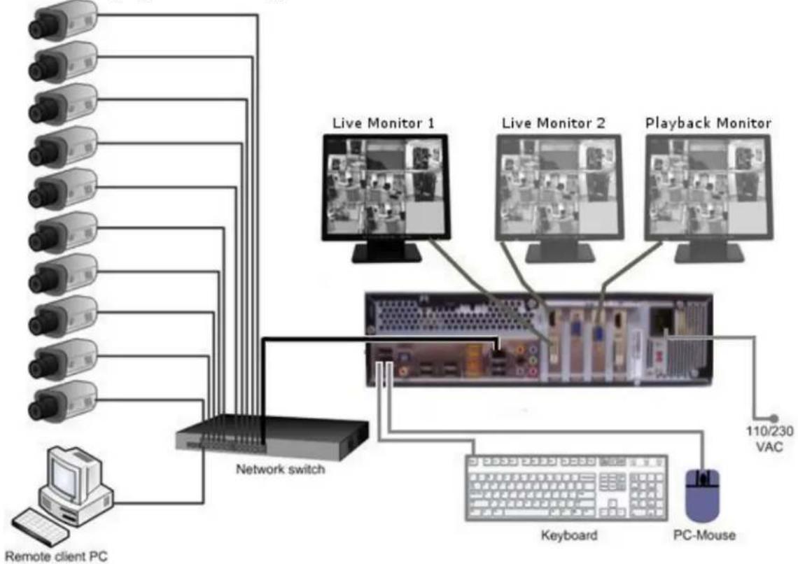
The NVR series is designed primarily for network recording on a Local Area Network (LAN). Performance while recording cameras which are connected with router/DSL lines via a WAN or the Internet will be highly dependent on network bandwidth and reliability.
For full performance it is recommended to install a separate network for the IP video security system. In addition, the LAN connection between network switch and NVR should support Gigabit network transmission.
The following figure shows a typical installation:
flowchart
graph TD
    A["Remote client PC"] --> B["Network switch"]
    B --> C["PC-Mouse"]
    C --> D["Keyboard"]
    D --> E["110/230 VAC"]
    B --> F["Live Monitor 1"]
    B --> G["Live Monitor 2"]
    B --> H["Playback Monitor"]
5 System Setup
5.1 First Time System Start
With factory default user settings the NVR will boot automatically and start the NVR software application without requiring Windows Login and Application login.
The NVR should start immediately after power is applied. If necessary, push the front power switch to start the NVR. By default, the NVR application starts with administrator user rights level. With these settings the NVR will also enter the record mode in case of a restart after power loss. For setup of user accounts including passwords please refer to Chapter 5.4.6 "User Account Settings". The default login is admin with no password
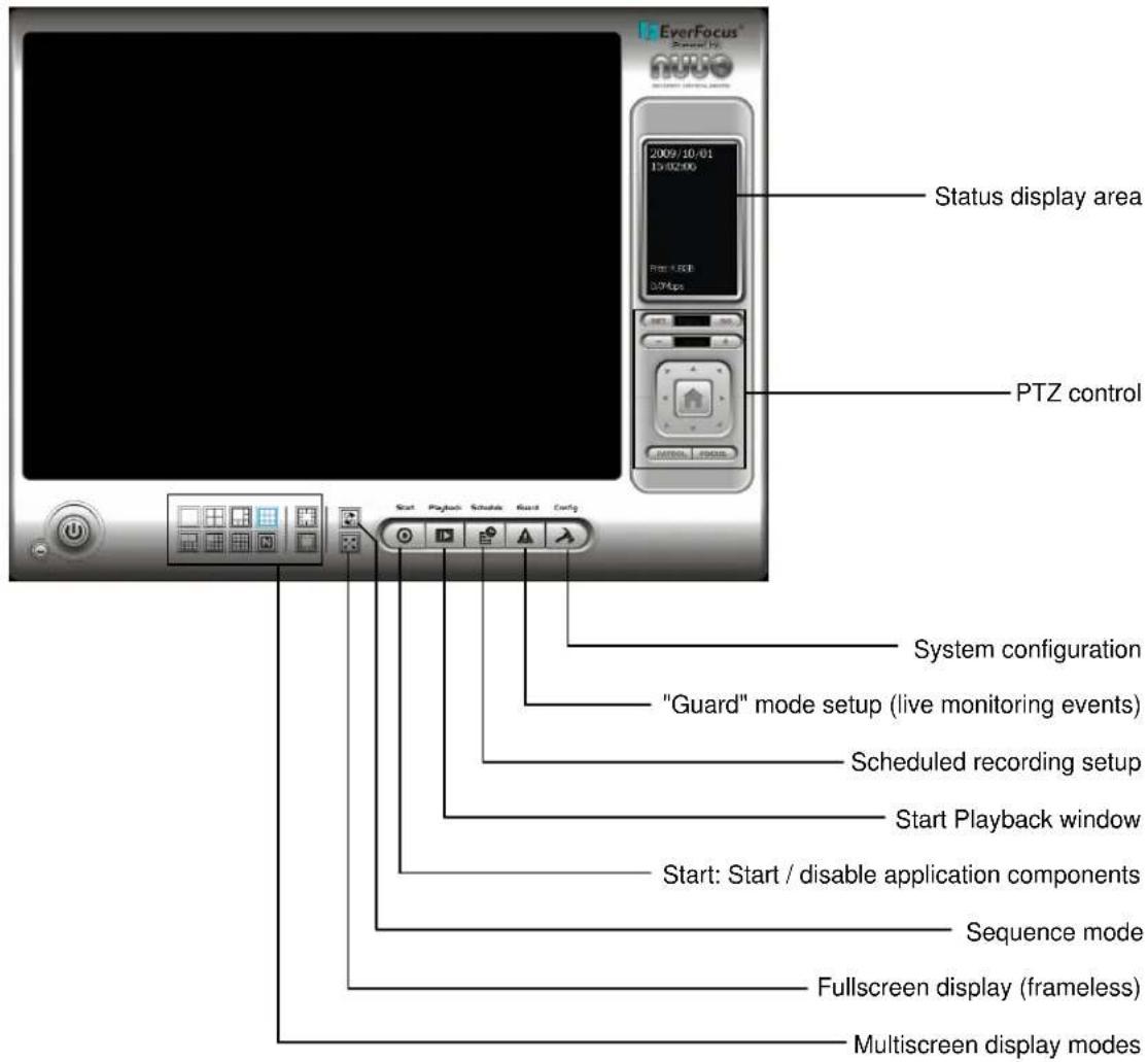
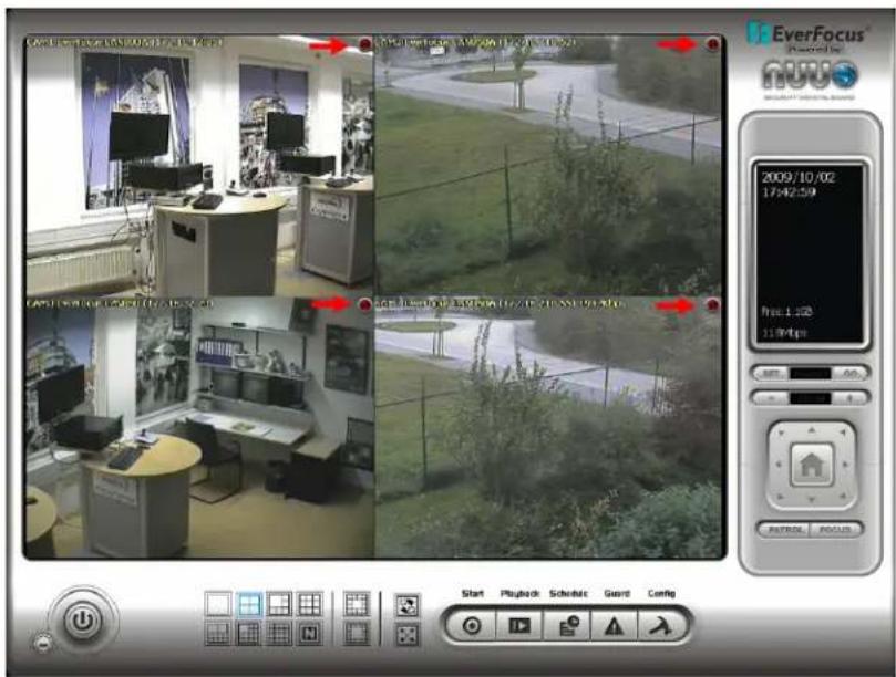
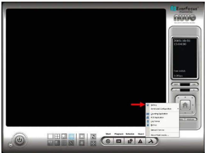
5.2 Main Console screen controls
After start-up the main screen will appear:
5.3 Quick Start Setup
This chapter describes the minimum installation steps to install IP-cameras for standard (continuous) recording.
Note: This quick start setup is based on the premise that all IP cameras in the system are installed in the same network and IP-address range as the NVR. The default IP - setting of the NVR is DHCP mode. If there is no DHCP host on the LAN, a static IP configuration must be assigned using Windows.
- Register your camera license serial number(s) (Internet connection required; for alternate methods see Appendix 9 Online License Procedures.)
A. Open "License Manager" Tool. Click CONFIG -> License Manager
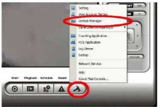
B. Select "On line" as Activate type.
Activate type:
On line
C Off line
C. Input the "SN (Serial number)", and then click on "Activate" button.
SN type:
Input SN:
C Import SN file:
○ Activate from dongle
Import license file:


D. Main Console will be restarted if activated successfully.

- Open camera setup menu >CONFIG >SETTING >tab CAMERA:
After selecting the tab CAMERA the screen shows camera setup with an empty camera list.
The camera setup supports 2 methods to install cameras:

+Search: Express setup for camera types, which support UPnP. (EverFocus Nevio IP camera series support UPnP).
+Insert: Manual input of camera data for camera types, which have no UPnP support.
Camera setup with SEARCH function
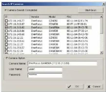
Click on +SEARCH to install cameras with UPnP support, a list with all available cameras appears:
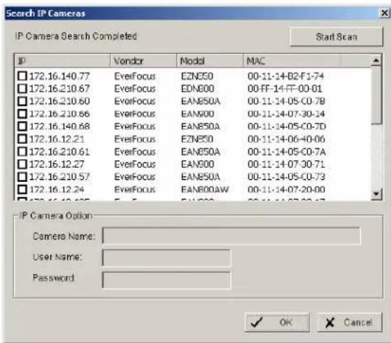
Select a camera to install and activate the checkbox at left side:
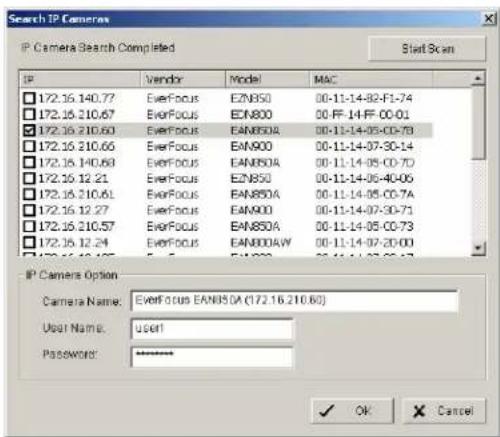
Enter user name and password for each camera and (recommended) the camera name.
Default user name and password for an EverFocus NEVIO cameras is:
User name (admin level): user1
Password: 11111111
After setting the desired cameras confirm with OK to add these cameras to the NVR camera list:
Manual IP camera setup
An alternative to the search function is to setup cameras, including IP settings, manually. Click the icon “+INSERT” to open the camera setting window:
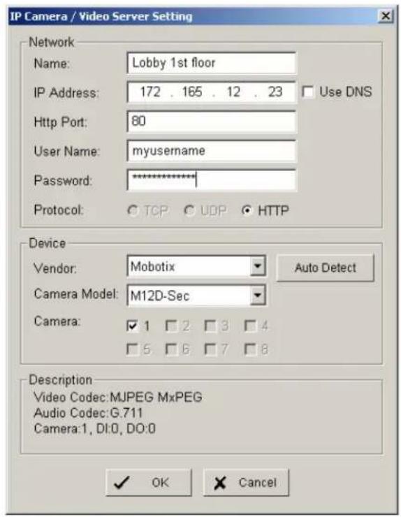
Enter Camera Name, IP parameters and user name / password.
Under DEVICE select a listed vendor and camera model or use the AUTO DETECT function. Click OK save these settings.
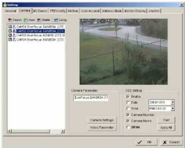
For changing frame rate and recording image quality, select a camera from the list and press the CAMERA SETTINGS button:

The window shows the current camera settings. Possible values depend on the camera type. Change the setting to fit the recording system requirements and confirm with OK.
It is also possible to adjust camera display settings; click on VIDEO PARAMETER:

After adjusting the display parameters confirm with OK.
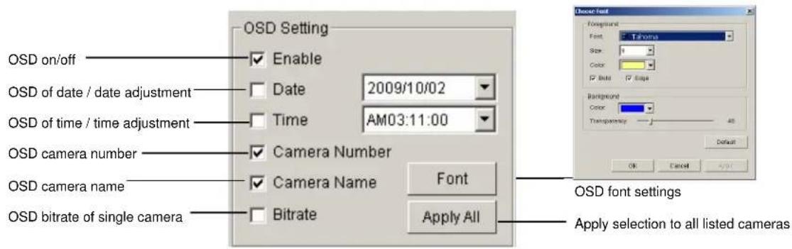
On lower right side of camera setup screen are additional settings for On Screen Display information which will overlay the camera display:
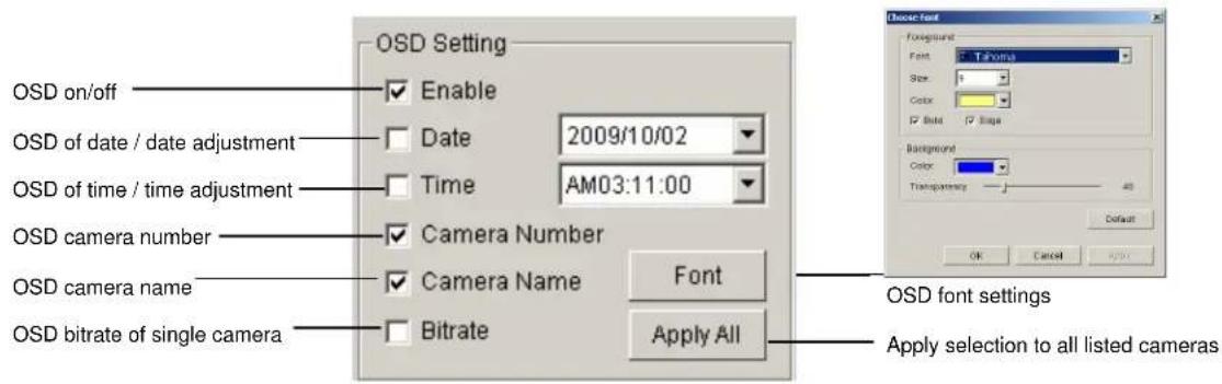
When settings are complete, click APPLY ALL to confirm for the selected (checked) cameras, then confirm with OK in the CAMERA setup menu.
Minimum settings in GENERAL menu.
Open camera setup menu >CONFIG > SETTING > tab GENERAL:
- Please verify that all recording HDD are entered correctly under STORAGE/LOCATION. These drives are the entered at factory by default, depending on the model.
- Check and adjust the other important recording settings:
Automatic Recycle: check the box and the NVR will delete the oldest records, if the recording HDDs are filled.
Recycle Range: interval (1h to 1 day), how often NVR checks to delete old records
Keep Video: If checked, the NVR will delete video data after a defined time period. If not checked, the NVR will use the full HDD capacity to achieve the maximum recording time.
If recording shall start automatically upon application start, mark the checkbox SCHEDULE RECORDING SYSTEM under START-UP.
Confirm all settings with OK.
With these basic settings the NVR is configured for continuous recording. For more detailed settings including schedule and event management refer to the following section DETAILED SETUP.
Finally choose the START button from the main window and choose START RECORDING SCHEDULE to activate recording. The menu is context sensitive, so if recording is already enabled, the menu choice will be 'Stop Recording Schedule'.
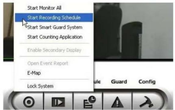
The system is now set to record; recording status is indicated by a red dot in the upper right on each recording video channel.
5.4 Detailed Setup
Following chapters describe the setup options of the NVR in all details.
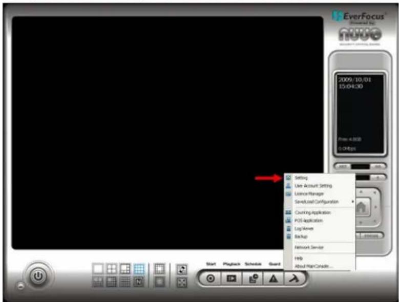
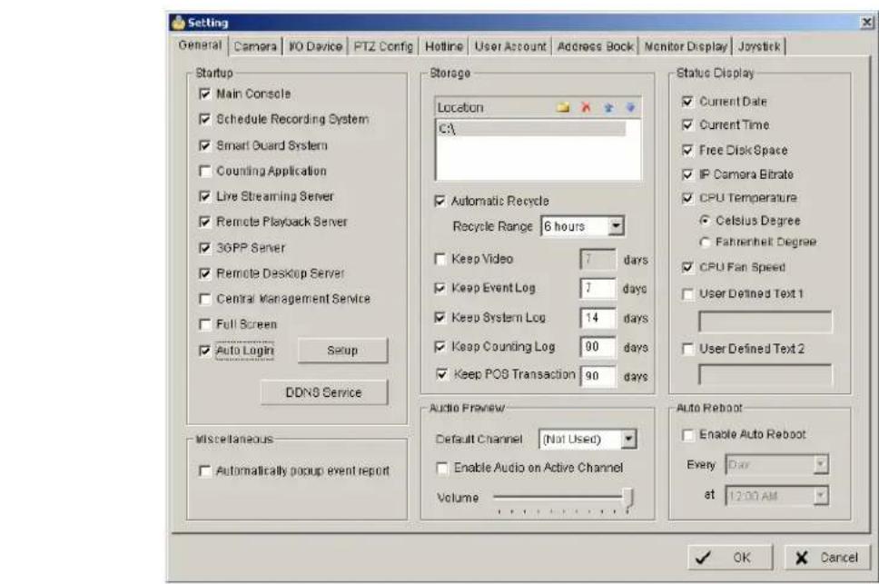
5.4.1 Setting - General
open with > CONFIG > SETTING
This menu defines general parameters, display and start-up behavior of the NVR.
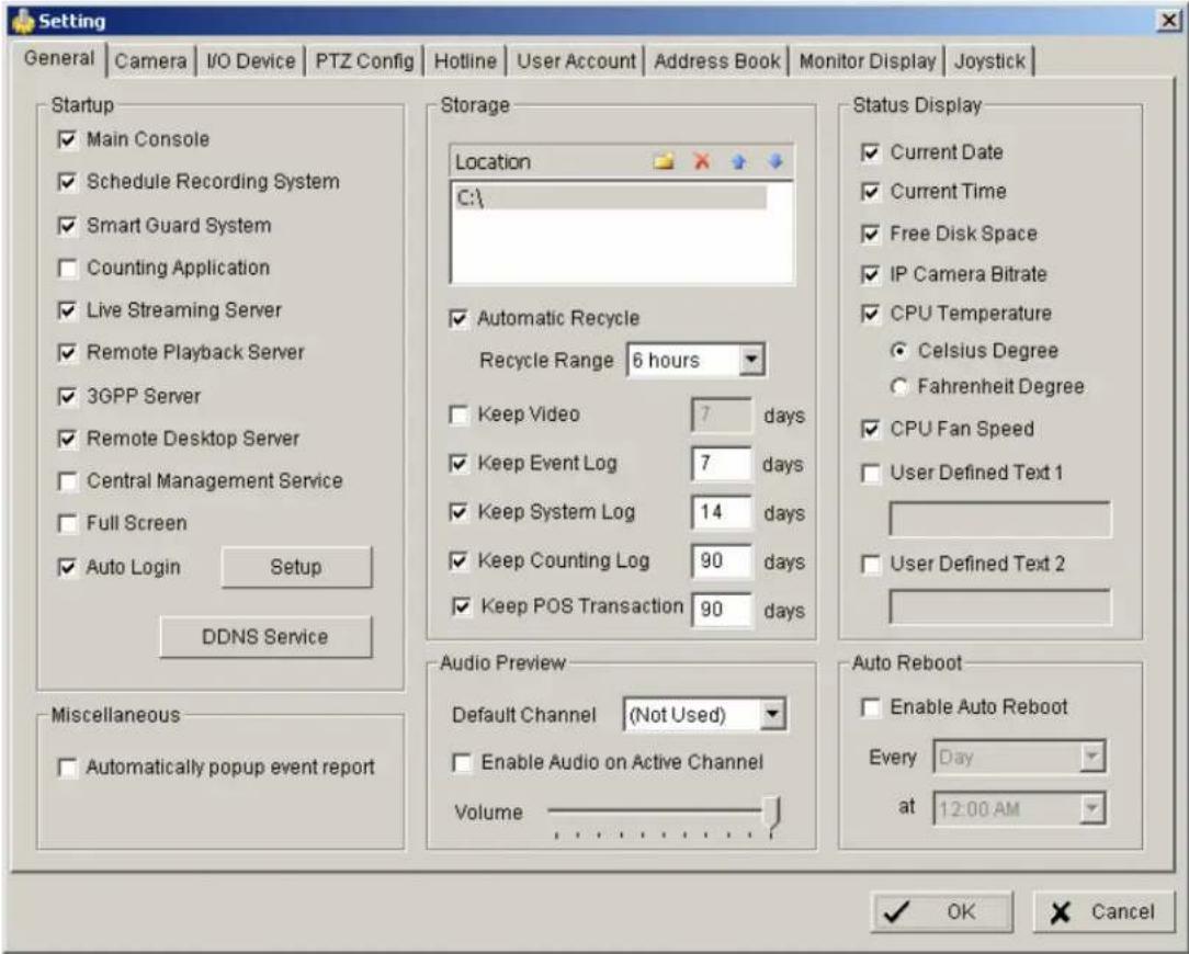
Start-up - Behavior of NVR after booting
Main Console: with this box checked, the NVR application starts automatically after Windows startup
Smart Guard System: with this box checked, ???? event management will be activated at NVR start
Counting application: with this box checked, the counting application will be activated at NVR start
Live streaming server: with this box checked, the streaming server for live view will be activated at NVR start
Remote playback server: with this box checked, the streaming server for playback view will be activated at NVR start
3GGP server: with this box checked, the 3GPP/mobile phone server will be activated at NVR start
Remote desktop server: with this box checked, the remote desktop server will be activated at NVR start
Central management reserved service:
Full screen: with this box checked, the NVR application will start in full screen mode
Auto login: with this box checked, the NVR application requires no manual login.
Storage - Settings for storage location and general recording parameters
Location List of recording HDD and recording path. Please check, if all drives are listed.
Automatic Recycle with activated checkbox the NVR will delete oldest records, if the recording HDD are filled.
Recycle range interval (1h to 1 day), how often NVR checks for deleting old records
Keep video If activated, the NVR will delete video data after a defined time period. If not activated, the NVR will use full HDD capacity for achieving max. recording time.
Keep event log If activated, the NVR will delete event log data older than the entered value in days
Keep system log If activated, the NVR will delete system log data older than the entered value in days
Keep counting log If activated, the NVR will delete counting log data older than the entered value in days
Keep POS transaction reserved
Audio Preview - Live monitoring audio settings
Default channel Select the audio channel, which is active in any multi-view without selecting a camera in this view
Enable Audio on Active Channel If activated, Audio output will change to selected camera channel
Volume Audio output volume
Status Display - Display options for global status display (right side of main screen)
Display options, displayed with activated checkbox
- Current time
- Current date
• Free disk space (total for all recording drives) - IP camera bitrate (summarised input stream)
• CPU Temperature (not supported)
• CPU fan speed (not supported) - User defined text 1 (free editable)
- User defined text 2 (free editable)
Auto reboot
With activated checkbox the system will reboot in defined time interval. If you use this function, make sure to activate under START-UP:
- Main console
- Schedule recording system
- Auto login
Otherwise the recording function will not recover automatically after reboot.
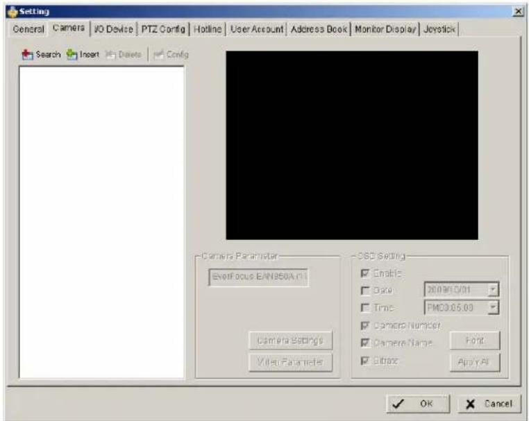
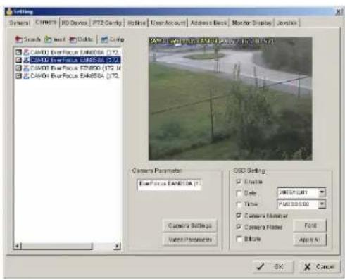
5.4.2 Setting - Camera
- Open camera setup menu >CONFIG >SETTING >tab CAMERA:
After selecting the tab CAMERA the screen shows camera setup with an empty camera list.
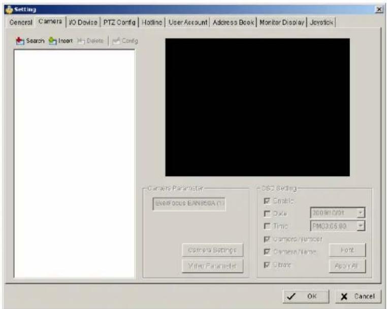
The camera setup supports 2 methods to install cameras:

+Search: Express setup for camera types, which support UPnP. (EverFocus Nevio IP camera series support UPnP).
+Insert: Manual input of camera data for camera types, which have no UPnP support.
Camera setup with SEARCH function
Click on +SEARCH to install cameras with UPnP support, a list with all available cameras appears:
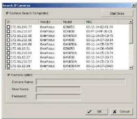
Select a camera for installing and activate the checkbox at left side:
Enter user name and password for this camera and if applicable the camera name. Default user name and password for EverFocus NEVIO cameras is:
user name (admin level): user1
password: 11111111
After setting the desired cameras confirm with OK to take over these cameras in the NVR camera list:
Manual IP camera setup
Alternative to the search function it is possible to setup cameras including IP settings manually. Click the button +INSERT to open the setup window:

Enter IP parameter and user name / password.
Under DEVICE select a listed vendor and camera model or use the AUTO DETECT function.
Click OK to take over the settings.
For changing frame rate and recording image quality select a camera from the list and press CAMERA SETTINGS button:
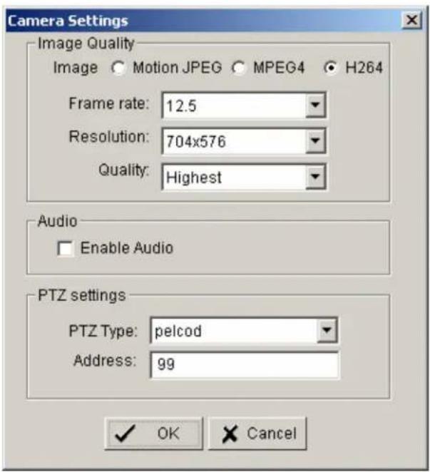
The window shows current camera settings. Possible values depend on camera type. Change the setting to the recording system requirements and confirm with OK.
Optional it is possible to adjust camera display setting, click on VIDEO PARAMETER:
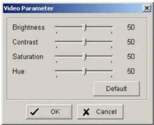
After adjusting the display parameters confirm with OK.
On lower right side of camera setup screen are additional settings for On Screen Display overlay display:
If all settings are done, confirm with OK in CAMERA setup menu.
5.4.3 Setting - I/O Device
This menu defines parameters for digital inputs and outputs of connected IP devices. The functionality depends on connected IP - devices.
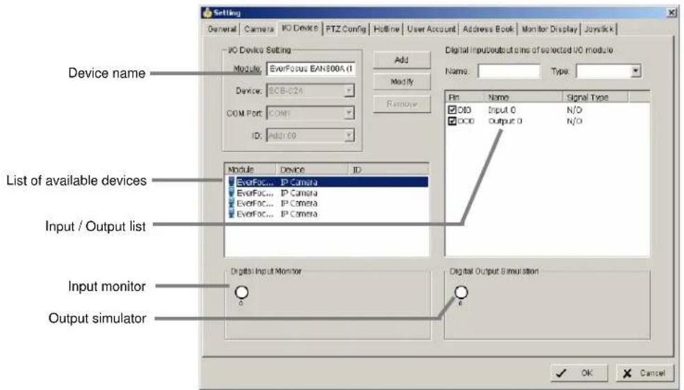
Module Setting Device name of selected IP device (as defined in CAMERA menu)
Add, Modify, reserved functions for IP-serial converters Remove, Device, Com port, ID
Device list List with available IP-devices, which provide I/O function
Digital Input Monitor The selected input is turned on if the dot is in red. By triggering the digital input device, the related icon will light up. This is used to check if the device is correctly connected or not.
Digital Output Simulation The selected output is turned on if the dot is in red. By clicking on the icon, you may trigger the digital device connecting to the system. This can be used to test if the output device is correctly connected.
Digital input/output pins of selected I/O module
Name Define the name of the device (input and output). Type Select the device type from the drop-down menu. N/O Normal Open. N/C Normal Close.
5.4.4 Setting - PTZ - Config
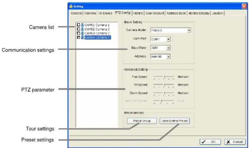
Camera list Available cameras in the system. Select one and activate checkbox for editing PTZ functions.
Basic settings Select the device type from the drop-down menu.
Com port not supported in NVR, greyed
Baud rate
Address
Advanced setting Speed setting for PTZ and Autopan (functionality depends on camera model)
Patrol group Submenu for defining preset tours of this camera, 4 tours are available
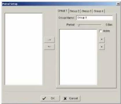
For creating a tour insert available presets from left list, adjust dwell time and turn on the checkbox "Active".
User defined preset Submenu for defining presets for special functions (depending on PTZ camera)
5.4.5 Setting - Hotline (communication settings)
This menu provides communication settings for mail, FTP, modem and phone. These settings are mandatory for several alarm reactions in GUARD mode (Send Snapshot to FTP, Phone call, Send SMS, Send e-mail).
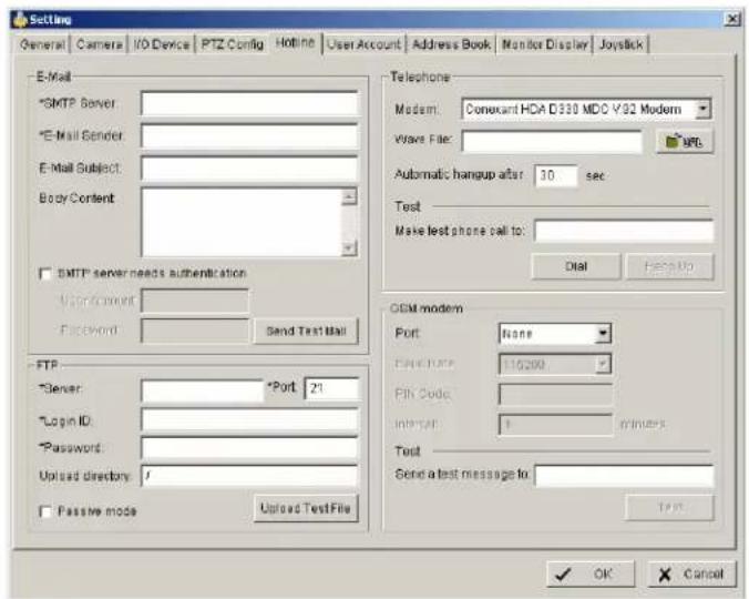
E-mail Input the following information:
server, sender's E-mail address, E-mail's subject title, and body content. You may click on the Send Test Mail button to test the settings.
Note: * indicates mandatory areas
FTP Input the following information:
server, Port, Login ID, Password, and Upload directory. According to your FTP type to enable/disable Passive mode. You may click on the Upload Test File button to test the settings.
Note: * indicates mandatory areas.
Telephone Select the modem that the system is going to dial the info call with, and then insert the phone number. (A modem is required for voice transition.)
Note 1. You must use a modem with voice capability.
- You may select a Wave format file; it will be played in the phone to alarm the person who picks up the phone call.
GSM modem Set the Port and Baud Rate of the GSM modem device, and then enter PIN code. You can setup the interval of send SMS message. You may click on Test to send test SMS message. Note: The interval is set to restrict the period of two SMS. If you set as 60 min, the SMS between 60 min would be deleted and didn't send to user.
5.4.6 Setting - User Account
The NVR recorders provide user right management with free assignable user rights for each user.
In factory setting 1 user with administrator rights is pre-defined:
user name: admin no password
For user setup are 2 groups of user rights defined:
Admin: all user rights (user rights can not be unchecked, for defining Administrators with limited user rights user the group USER)
User: user group with free assignable user rights per user Factory settings: enabled: Main console, Live view, Playback View, Remote live view, all others disabled
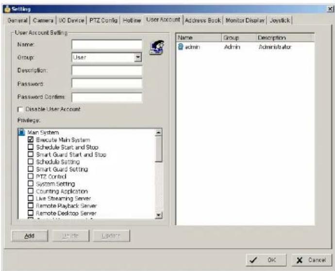
Add Creates new user account.
Enter name, description and password and define the user rights. Then click on ADD to create the account.
Delete Select an account from the list on right side and click on DELETE to remove this account.
Modify Select and account from the list on right side. Modify name / description / password and click on MODIFY for taking over the changes.
Disable Deactivates a selected account without deleting the account.
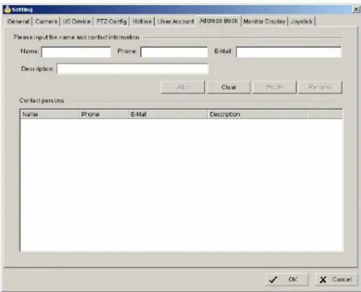
5.4.7 Setting - Address book
Contact person settings are required for GUARD mode event reactions "Phone call", "Send SMS" and "Send mail".
Enter the required data. Already defined contact persons are listed in lower part of the window.
5.4.8 Setting - Monitor display
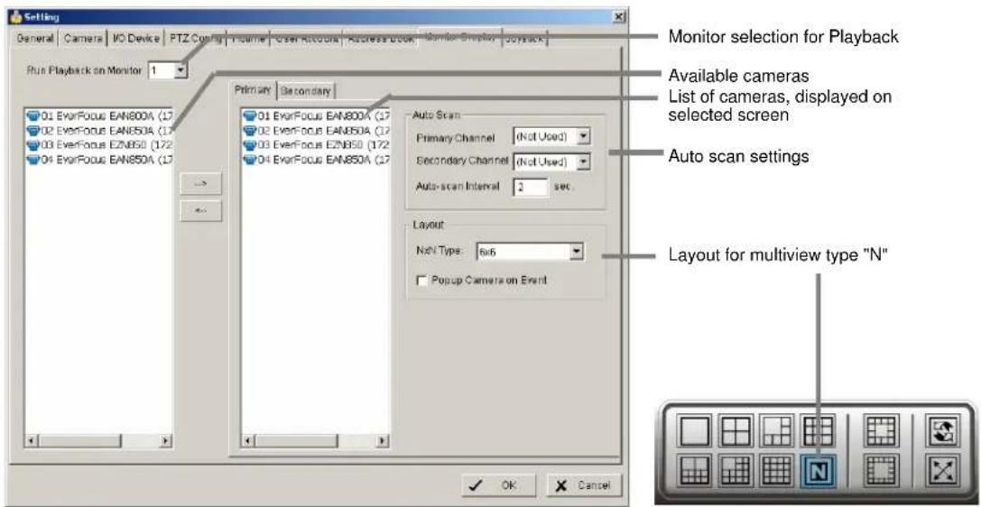
Run Playback on Monitor
Selection of monitor output 1 or 2 for playback window
Primary / Secondary Use the arrow buttons in the middle to add / remove cameras from the list of selected monitor. Removed cameras will not be displayed at this monitor.
Auto scan
Primary channel "Not used" will scan all channels, which are assigned to primary monitor in order. If a channel is selected, this channel will be displayed every second step.
Example: "Primary Channel: Ch. 3":
Sequence: 1 > 3 > 2 > 3 > 4 > 3 > 5 > 3 > 6.....
Secondary channel "Not used" will scan all channels, which are assigned to secondary monitor in order. If a channel is selected, this channel will be displayed every second step.
Example: "Primary Channel: Ch. 3":
Sequence: 1 > 3 > 2 > 3 > 4 > 3 > 5 > 3 > 6.....
Auto scan interval Dwell time for interval switching in seconds
Layout
NxN type Layout for the free definable multiview "N": 4x4, 5x5 or 6x6
Popup camera on Event
If checkbox is active, cameras will switch to full screen in case of live events.
Note: If secondary monitor is used, make sure to enable this monitor under > START > ENABLE SECONDARY DISPLAY
5.4.9 Setting - Joystick
The NVR series supports EKB-200 joysticks and other HID compatible USB Joysticks. If the system detected a joystick, NVR will show the setup options under the tab JOYSTICK. Without connected joystick the options are greyed and not active.
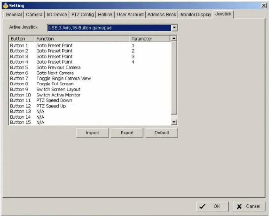
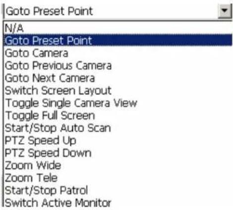
Selectable options for key assignment of the Joystick are:
5.5 GUARD - live event / event action configuration
The GUARD mode allows live monitoring with automatic event reactions, triggered by intelligent video analytics functions.
For the settings click on GUARD in Main screen:

The menu screen shows all installed systems in the left side list, which can be used as event source.
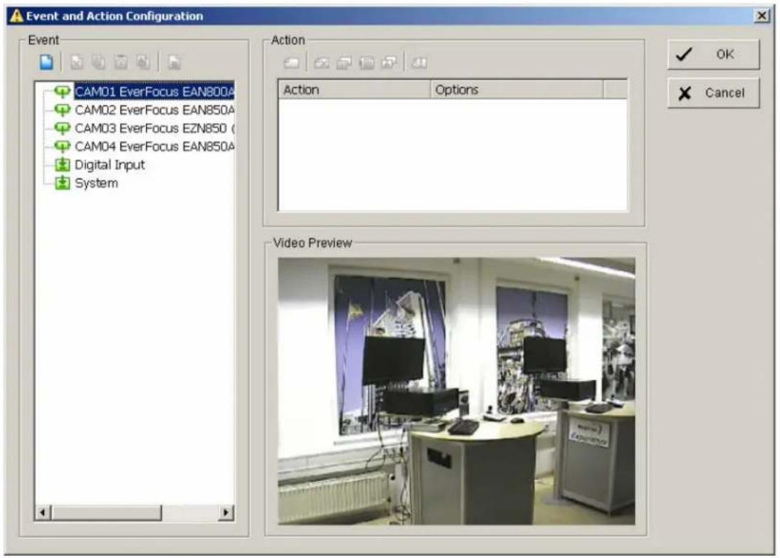
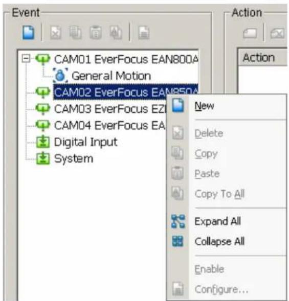
For defining an event select a device from the list and open with right click > NEW the context menu.
5.5.1 Event types
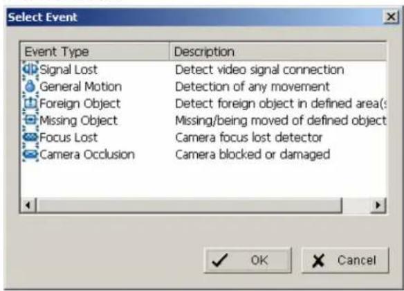
Depending on the device you will get a choice of available event types:
For cameras:
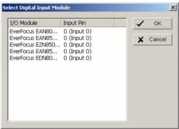
For input contacts:
For system events:
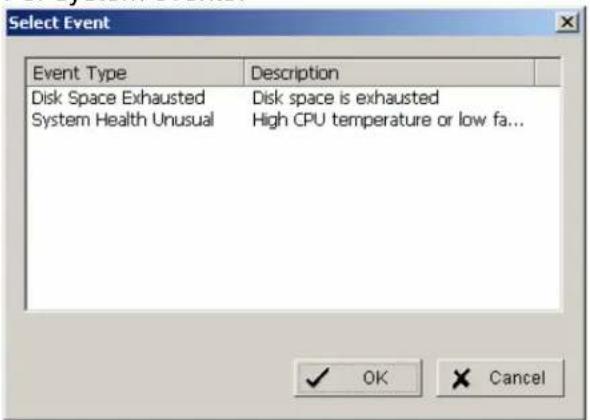
The setup options for the event types are described in following chapters
5.5.1.1 Signal lost event
Indicates signal loss from this camera.
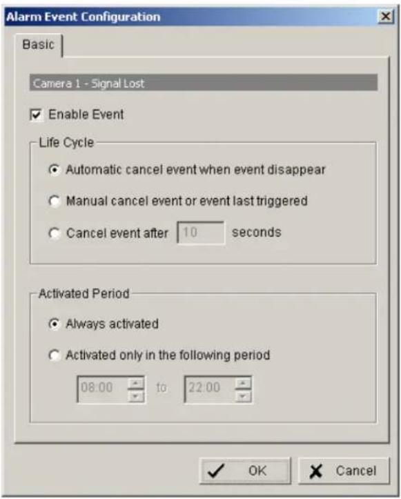
Options:
Life Cycle Definition, how long the message is shown
Activated Period Permanent (Always Activated) or scheduled function (daily time period)
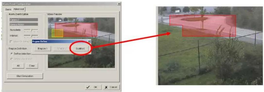
5.5.1.2 General motion event
The GENERAL MOTION event allows motion detection in free definable square detection areas.
ADVANCED
For defining a detection area draw a window by mouse in the video window. Confirm setting with "REGION1".

You can add more detection areas by drawing in the video window and confirming by "REGION1".
Cutting out areas from detection zones is possible by confirming with "SUBTRACT":
Sensitivity Sensitivity of motion detection, moving slider to right increases sensitivity, moving to left decreases sensitivity.
Interval Filter function for motion detection. If slider is moved to right, a longer movement period is needed to trigger alarm
Start / Stop Simulation
With START SIMULATION you can test, if current settings are correct. Detected motion areas are displayed in yellow, below the video window appears "Event detected".
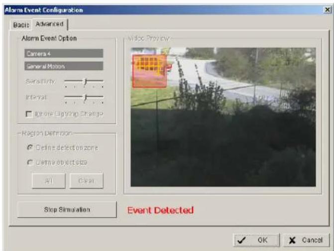
End the simulation mode with "STOP SIMULATION".
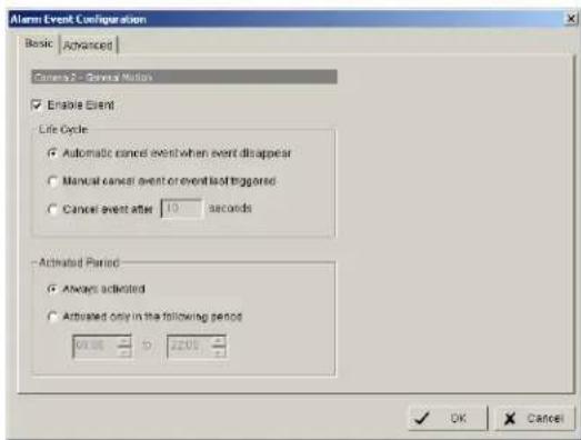
BASIC
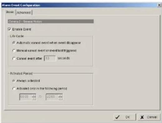
Options:
Life Cycle Definition, how long the message is shown
Activated Period Permanent (Always Activated) or scheduled function (daily time period)
5.5.1.3 Foreign object event
This event type creates an event if an unexpected object appears in a defined zone.
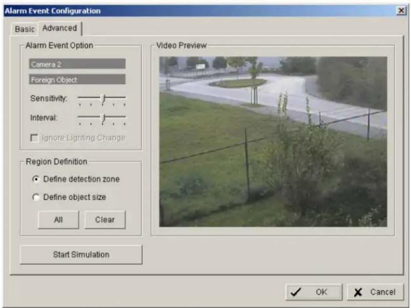
Define detection zone Draw the detection zone by mouse in the video window and confirm wit "REGION1". You can also add and subtract areas, as described in detail under "GENERAL MOTION".
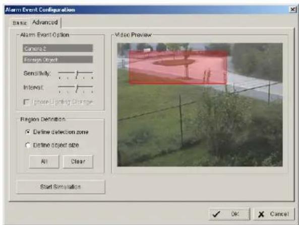
Define object size Draw in the video window an area in the expected size of the object.
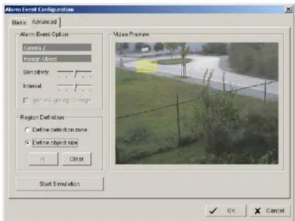
Sensitivity Sensitivity of detection, moving slider to right increases sensitivity, moving to left decreases sensitivity.
Interval Filter function for detection. If slider is moved to right, a longer period of object appearing in detection zone is needed to trigger alarm.
Start / Stop Simulation With START SIMULATION you can test, if current settings are correct. Detected objects are displayed in yellow, below the video window appears "Event detected". End the simulation mode with "STOP SIMULATION".
BASIC
Options:
Life Cycle Definition, how long the message is shown
Activated Period Permanent (Always Activated) or scheduled function (daily time period)
5.5.1.4 Missing object event
The event type MISSING OBJECT allows to monitor automatically objects in the camera field of view. Removing of the object will trigger an event.
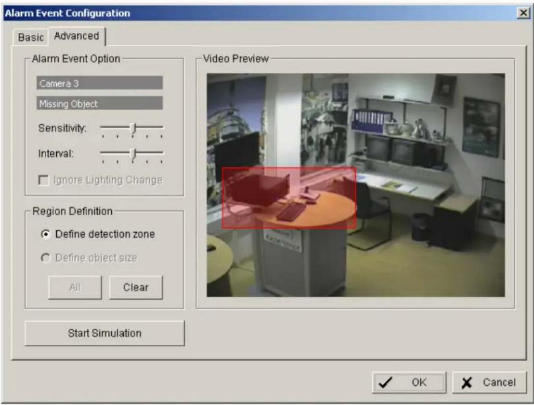
Define detection zone Draw the detection zone by mouse in the video window and confirm wit "REGION1". You can also add and subtract areas, as described in detail under "GENERAL MOTION".
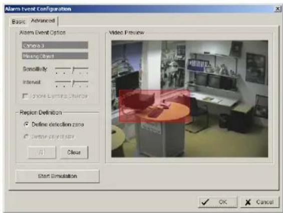
Sensitivity Sensitivity of detection, moving slider to right increases sensitivity, moving to left decreases sensitivity.
Interval Filter function for detection. If slider is moved to right, a longer period of object disappearing in detection zone is needed to trigger alarm.
Start / Stop Simulation With START SIMULATION you can test, if current settings are correct. Detected movements are displayed in yellow, below the video window appears "Event detected". End the simulation mode with "STOP SIMULATION".
BASIC
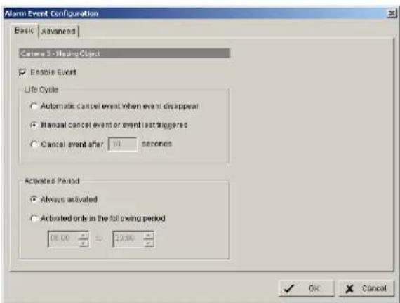
Options:
Life Cycle Definition, how long the message is shown
Activated Period Permanent (Always Activated) or scheduled function (daily time period)
5.5.1.5 Camera occlusion event

Sensitivity Sensitivity of detection, moving slider to right increases sensitivity, moving to left decreases sensitivity.
Interval Filter function for detection. If slider is moved to right, a longer period of camera occlusion is needed to trigger alarm.
Ignore Lighting change With activated checkbox the event will not trigger, if a global light change (turn light on / off) appears in the camera picture.
Start / Stop Simulation With START SIMULATION you can test, if current settings are correct. Below the video window appears "Event detected". End the simulation mode with "STOP SIMULATION".
BASIC
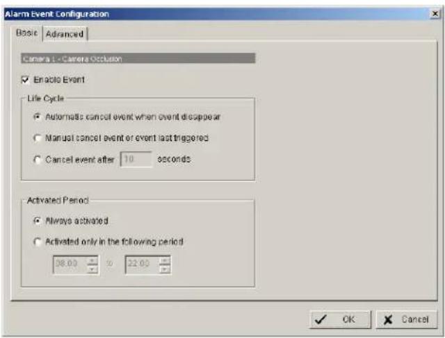
Options:
Life Cycle Definition, how long the message is shown
Activated Period Permanent (Always Activated) or scheduled function (daily time period)
5.5.1.6 Focus lost event
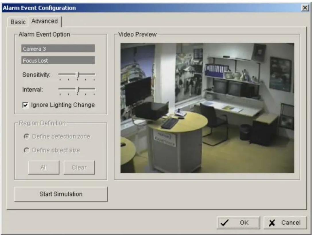
Sensitivity Sensitivity of detection, moving slider to right increases sensitivity, moving to left decreases sensitivity.
Interval Filter function for detection. If slider is moved to right, a longer period of unfocussed camera is needed to trigger alarm.
Ignore Lighting change With activated checkbox the event will not trigger, if a global light change (turn light on / off) appears in the camera picture.
Start / Stop Simulation With START SIMULATION you can test, if current settings are correct. Below the video window appears "Event detected". End the simulation mode with "STOP SIMULATION".
BASIC
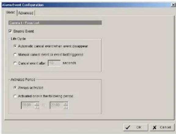
Options:
Life Cycle Definition, how long the message is shown
Activated Period Permanent (Always Activated) or scheduled function (daily time period)
5.5.2 Event actions
Each defined event can be assigned to one ore more event actions. Select an event at left side list and click on "INSERT ACTION"
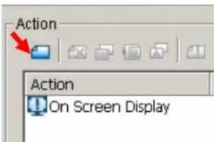
or open context menu by right click and select NEW:
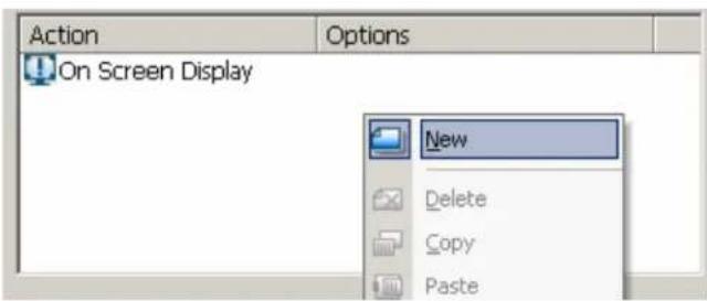
Available event actions are:
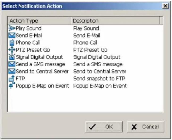
The event actions are described in following chapters.
5.5.2.1 Event action: Play sound
After selecting PLAY SOUND as event action and double click opens a window for selecting the sound file.
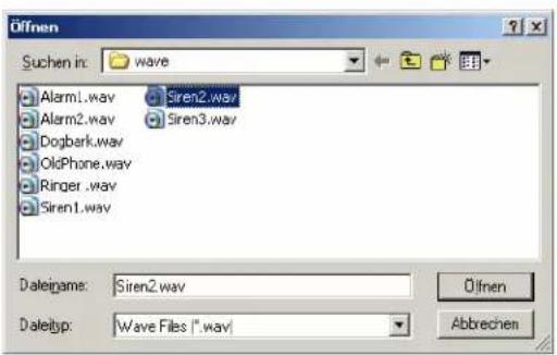
Select a file and confirm with OPEN.
5.5.2.2 Event action: Send E-mail
After selecting SEND E-MAIL as event action and double click opens a window with a list of available contact persons (setup in > CONFIG > SETTING > ADDRESS BOOK required):
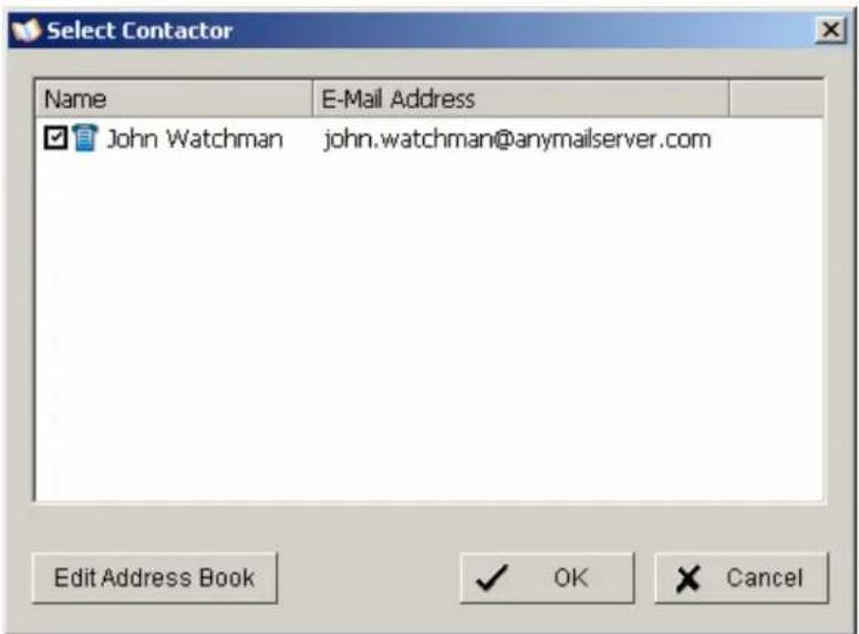
Select a contact for E-Mail notification and confirm with OK.
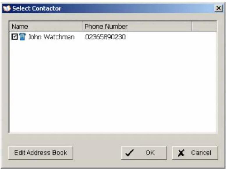
5.5.2.3 Event action: Phone call
After selecting PHONE CALL as event action and double click opens a window with a list of available contact persons (setup in > CONFIG > SETTING > ADDRESS BOOK required):
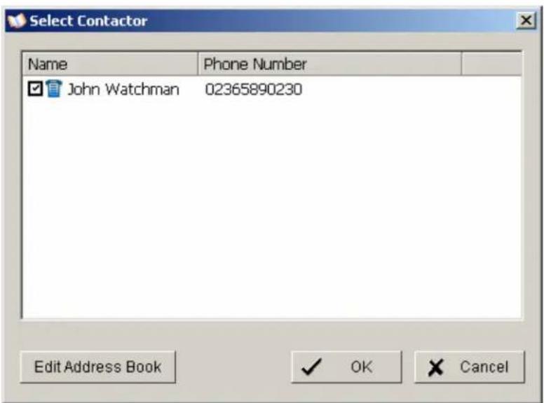
Select a contact for phone call notification and confirm with OK.
5.5.2.4 Event action: PTZ preset go
This event requires PTZ cameras with preset function in the system.
After selecting PTZ PRESET GO as event action and double click opens a window for selecting the PTZ camera, preset position and event related parameters.
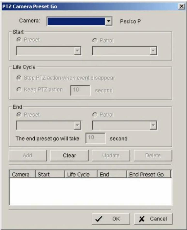
Confirm the entered values with OK.
5.5.2.5 Event action: Signal digital output
This event action allows to switch a contact output of an installed IP-device.
After selecting SIGNAL DIGITAL OUTPUT as event action and double click opens a window with all available digital output contacts in the system:
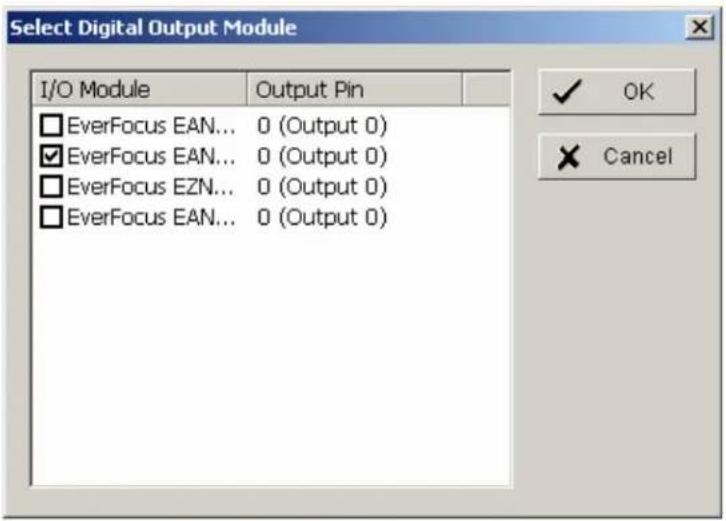
Activated the checkbox at desired contact output and confirm with OK.
5.5.2.6 Event action: Send a SMS message
After selecting SEND A SMS MESSAGE as event action and double click opens a window with a list of available contact persons (setup in > CONFIG > SETTING > ADDRESS BOOK required):
Select a contact for SMS notification and confirm with OK.
5.5.2.7 Event action: send top central server
Reserved for future functions
5.5.2.8 Event action: Send snapshot to FTP
In case of an event the system will send a snapshot to the defined FTP server.
This event action requires FTP-server setup under >CONFIG > SETTING > HOTLINE > FTP.
5.5.2.9 Event action: Popup e-map on event
This event type allows display of an event in e-map (automatic popup).
Required is a configuration of e-map under > START > E-MAP
After selecting POPUP E-AP EVENT as event action and double click opens a window with a list of available maps and indicators (icons on maps):
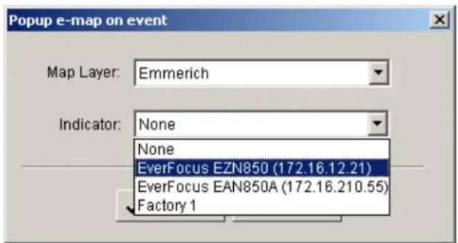
Select a map and desired indicator (icon) and confirm with OK.
5.6 Schedule setup
The NVR allows continuous, scheduled or event controlled recording. The recording behaviour is defined in the SCHEDULE menu.
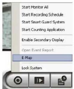
Open the SCHEDULE menu from MAIN console:
Schedule

In factory setting the system will record all cameras in continuous mode.
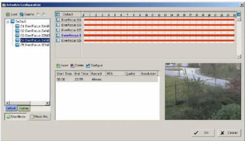
5.6.1 Setup new schedule manually
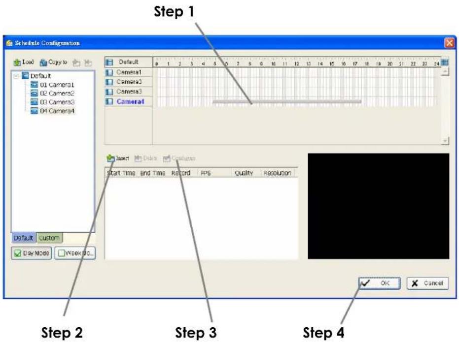
Step 1 Left-click and draw the bar to the time table. The scheduled time will appear as a grey bar.
Step 2 Click the Insert icon and add a new schedule in the Regular Mode, i.e. to record video during the time period you set with 30 FPS, Normal video quality, and Normal resolution.
Step 3 Change the setting if wished by clicking on the Configure icon (See 3.7 Encoding Option Panel) or double click the schedule information.
Step 4 Click OK.
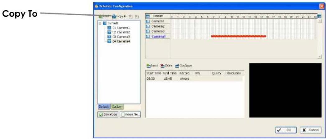
5.6.2 Copy Schedule
You may set up the schedule for each channel/camera by repeating the process above, or simply apply the setting of a single camera to all the others.
5.6.3 3.5 Week Mode
Schedule the cameras for each day of the week differently. In addition, you may assign extra holidays under the Week Mode.
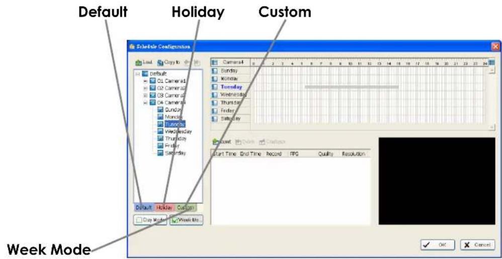
Default Follow the same process to setup the schedule for every day in a week.
Holiday You may assign holidays where the system will work according to the setting of Sunday.
Custom You can assign a particular date(s) on which the system will work according to a special schedule(s) different from the others.
Adjust the Scheduled Setting: You can manually change the setting at any time after you insert or load a period of schedule.
Option 1: Move the cursor to the Time Bar and change the length or move the bar sideway to change the start and end points.
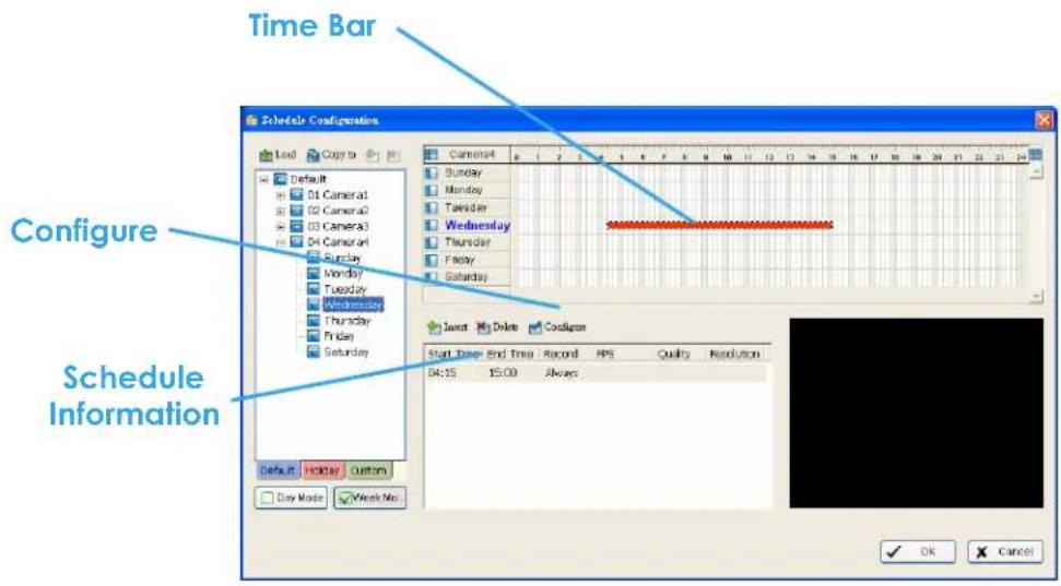
Option 2: Click on the Configure icon or double click on schedule information on the screen (highlighted in blue) to obtain the Encoding Option panel (next page) and change the setting as wished.
Configure: Click on the configure icon to obtain the Encoding Option panel.
5.6.4 Conigure - Encoding Option Panel
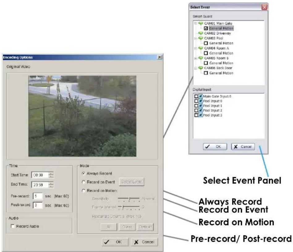
Always Record Select this option to record the video at all time.
Record on Event Select this option to obtain the Select Event panel. From the Smart Guard list, check the box of the camera(s) that you want to trigger the recording action. Click OK to complete the setting.
Note: This option needs start Smart Guard to trigger the recording schedule.
Record on Motion Select this option to start recording when there are motions detected.
To detect Motion, you have to define a detection zone. Left-click and drag the mouse to draw a detection zone. You may define more than one zone on the screen by repeating the same process.
User can also click on "All" button to select the entire detection zone. You may adjust the sensitivity and the frame interval.
Pre-record/ Post-record Time The pre-record/ post-record function saves the recording data accordingly. For instance, to set up a 5 second pre-record time means the system will start saving the recording data 5 seconds before the event happens.
5.7 E-Map
The NVR series provides an e-map function, which allows to show location of installed IP - Devices on maps or other graphics.
In GUARD mode the map can popup automatically in case of an event and show the event location including preview of the event camera.
For setup of e-map go to > START > E-MAP.
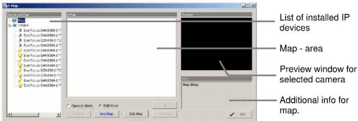
Select "Edit mode".
Click on "ADD MAP"
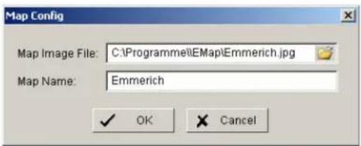
Enter the map or image file. Accepted file formats are BMP, JPEG, TIFF, PNG, GIF. Assign a map name and confirm with OK.
The map will appear in the middle window and the map name is listed in the device list on left side.
For placing a camera or contact on the map drag an item from device list and drop on the map at desired location.
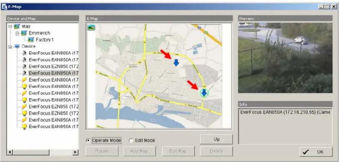
After finalising the layout finish the edit mode by clicking on OPERATE MODE.
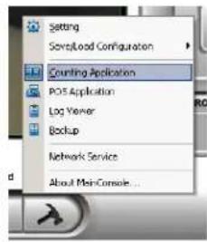
5.8 COUNTING APPLICATION
The integrated Counting Application allows to count the number of persons, cars or other objects in one or both directions.
The counting results can be shown in the camera live view. For evaluation of counting results the NVR provides a log with diagrams for definable time periods.
For setup go to > SETUP > COUNTING APPLICATION
Define Detection Zones The counting application requires 2 detection zones in the camera picture. These are used to count movements between these zones. Define zones REGION1 and REGION2 by drawing with mouse in the video window.
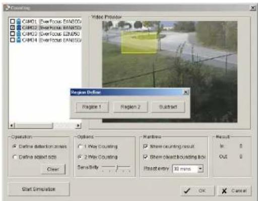
Define Object Size Define the estimated object size by drawing in the video window.
If necessary, the object size has to be adjusted again after running simulation (in case of no safe detection).
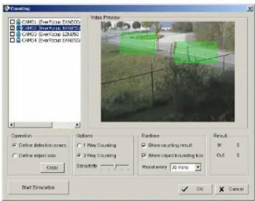
![Coating CAP01 [Exifocus EAN80D] CAP02 [Exifocus EAN80D] CAP03 [Exifocus EAN80D] CAP04 [Exifocus EAN80D] Video Preview Operation Define detection zones Define object size Clear Options 1 War Counting 2 War Counting Sensitivity Runtime Show counting result Show object boarding box Reset every 30 mins Result In: 6 Out: 6 Start Simulation OK Cancel](/content/2026/06/1184203/images/a61f74e52686250079e03a2f304bad351af5c08d1f87091edbf0bc876d8f6e62.jpg)
Options 1 Way Counting: Application will count movements from
REGION 1 to REGION 2 only.
2 Way Counting: Application counts movements in both directions
Sensitivity: Adjust the detection sensitivity
depending on the scenery. Use the simulation mode for test. This setting is also related to OBJECT SIZE setting.
Runtime
Options for live - display:
Show Counting Result
The number of counted movements is shown as overlay in the live view of the camera.
Show Object Bounding Box
Counted objects are marked in live view of the camera.
Reset every.... Time interval for resetting the counting result display in
the camera.
Start / Stop Simulation
After setting the parameters the settings can be tested in simulation mode. Counting results are shown under RESULT in lower right corner.
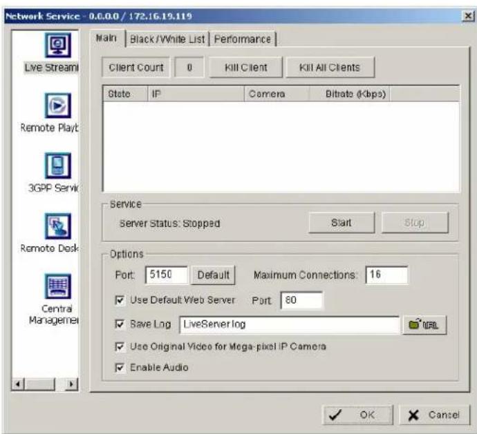
5.9 Network Services
For remote access to the NVR system are Server - functionalities required. The functions are managed and defined under NETWORK SERVICE.
For setup go to > CONFIG > NETWORK SERVICE.
5.9.1 Network service: Live Streaming
This service allows connections from other client PCs to the NVR by "REMOTE LIVE VIEWER" application or web browser.
MAIN
The list in the middle shows currently existing live connections (empty in screenshot).
Performance
This tab shows current network streaming performance for total system and for selected live connection. 5.9.2 Network Service: Remote Playback
When starting the remote playback function of your computer, you allow remote users to log on to the specific computer and withdraw data files that are stored on it. As system administrator, you are able to monitor the accounts that log on in order to maintain the system efficiency. Main On Remote Playback Server panel, you can see the clients who are currently logging on to your computer and watching the live video from the remote side.  Service Start / Stop By clicking on START the server function for playback view is enabled. Clicking on STOP disables the service Kill Client Stops remote connection to selected connection from the list Kill All Clients Disables all current connections OPTIONS NOTE: Changing Server options is only possible, if the service is stopped. Port Network port for remote live view. All remote client PCs have to use this port for remote access. Maximum Users Number of connections that are allowed to connect to the Remote Playback Server. Default is 8 accounts and maximum is 64, one account counts as one connection.User Default Web Server
If checkbox is activated, clients will be able to watch playback video via Internet Explorer. The port for live streaming server is set to 80 by default. Save log Save log file to specific folderBlack / White List
Remote live access to NVR can be filtered by a White List (selected IPs can access) or a Black List (selected IPs are blocked for access).  White List Check the "Enable White List" box to activate the white list filter. Only IP from the white list is allowed to log in. Black List Check the "Enable Black List" box to activate the black list filter. IP from the black list will be blocked. IP Address Enter an IP address into the IP address field on the left. To add an IP address range to the system, enter 2 sets of IP address to indicate a complete range of IPs. Add/Delete Add the entered IP(s) onto the list or remove it from the list. Apply to All Playback Servers To apply the setting to both live streaming server and remote playback server.Performance
This tab shows current network streaming performance for total system and for selected live connection. 5.9.3 Network Service: 3GPP Service
When starting the 3GPP service function of your computer, you allow remote users to log on the 3GPP supported mobile phone and view cameras that are connected to it. See Appendix B for more details about 3GPP Service.  Service Start / Stop By clicking on START the server function for 3GPP service is enabled. Clicking on STOP disables the service OPTIONS NOTE: Changing Server options is only possible, if the service is stopped. Port Network port for remote 3GPP view. All remote users have to use this port for remote access.5.9.4 Network Service: Remote Desktop
When starting the Remote Desktop option of your computer, you allow remote users to use Remote Desktop Tool to login and configuration system. See Appendix C to install and use this tool.  Port Assign a port for Desktop tool to login and configure system. Disconnect idle client after (300\~3600 sec): Auto disconnect the on-line user who idled more than defined period.Authentication
Enable this option would only allow admin account to use Desktop tool to login system.Server Status
Click on Start/Stop to turn on/off this service.5.9.5 Network Service: Central Management
This functionality is reserved for future application.6 Appendix A: DB TOOL
The DB Tool Repair database files and Export configurations. NOTE : improper use of this DB Tool may cause lose of the recorded video data. Step 1: Execute DB Tool from program files.  Step 2: Enter the password of administrator to login. 6.1 Repair Database
This page has three repair method, Modify Location, Verify Only, and Repair. For modify location propose: Playback system can recognize all recording video in the folders which list on Main Console > Config > Setting > General page. For some reason, user need use Playback system to open recording video beyond storage location setting. For this propose, user could follow below steps to modify location by DB tool. Note: The default storage location of system is on your\_installation\_directory, (ex: C:\Program Files\NUUO\SCB\_IP)Step 1: Select Repair database.
Step 2: Select the repair Method as Modify Location.
 Step 3: For add database location, please click on button and use URL to choose location. For remove database location, please choose location form list and click on button to remove location.  Step 4: Click on Modify button to modify location. After modification, the Modify Result will show on the panel. Example of database modification:
In certain case that when video data needs to be transfer from old PC to another new PC, user will need to perform the following procedure. 1. Manually copy all recorded video data from the default installation path or other user-defined storage path of the old PC.  2. Manually paste all recorded video data to the default installation path or other user-defined storage path of the new PC 3. Follow previous page to add new location on new PC. 4. Old recorded video data can be viewed by playback system on the new PC. For verify and repair proposes: This tool is using to check and repair your database and recording video with below problems: (1) If there are records in database, but no video file, use this DB Tools to delete records. (2) If there are video files but no record in database, use this DB Tools to rearrange the database and find these records. Step 1: Switch to Repair database windows.  Step 2: Select the repair Method as Modify Location.  Step 3: Check the video location windows. The system will list all video locations in table, but if there are any omit, please use to insert. Note: After inserting location, the system will show files count below table. File Count 41 Step 4: Choose the method of "Verify Only", and click "verify". This method will only check the files without modify. Verify result will show how many files broken or missing. Verify Result: 41 files verified, 0 files broken, 0 files missing.  Step 5: Choose the method of "Repair(Complete)", and click "Repair" to repair. The Repair Result will show how many files are fixed and inserted. Repair Result: 2 files fixed, 41 files inserted.  Step 6: The repair new database will replace old ones. And the original database will change file names with extend repair date and time as below.  Note: Open Log is a tool to record repair database recode. It will recode repair method, file operation, start time and end time. 6.2 Export Configurations
This tool allows to export the complete configuration to a file. Step 1: Press "Export".  Step 2: Select the location you want to Export and type the name of the configurations. Step 3: Press "Save" to start to import database. 7 Appendix B: 3 GPP setup examples
How to setup 3GPP streaming connection (using BenQ-Siemens mobile phones)7.1 Configuration in NVR
Step 1: Go to Config and select Network Service Step 2 : Select 3GPP Service, and then click Start
Note: In the Option item, the port selected here is the same port from mobile handset 7.2 Configuration Mobile Phone
7.2.1 BenQ-Siemens E81
Step 1: Goto Menu, then Internet  Step 2: Select Bookmarks  Step 3: Add New Bookmark  Step 4: Configure the Address setting as the following example. Ex: rtsp://61.216.97.69:554/media00.3gp 61.216.97.69:554 is the IP address of NVR system Port : port specified in 3GPP Service in NVR system  Step 5: Save the settings and start playing7.2.2 BenQ P50
1. Connect GPRS
 2. Download and install the [PLATFORM4] software. 3. Execute Main Console. 4. Press the [Config]→[Network Service]→[Start]  5. Open [PLATFORM4], press the button framed by red into Option  6. [Open Url] enter the rtsp address of the camera (EX: rtsp://61.216.97.69/media00.3gp→channel 1 EX: rtsp://61.216.97.69/media01.3gp→channel 2 EX: rtsp://61.216.97.69/media02.3gp→channel 3)  7. [Setting I]change the setting and press "OK" [Protocol] TCP [Buffer Size] 60 [Connection TimeOut] 103 [Data Recept.TimeOut] 100 [Deblocking Filter] check  8. Go back to PLATFORM4, searching and then getting the video  8 Appendix C: Installation of Remote Desktop Tool
Installation
Step 1: Insert the Installation CD. Step 2: Please go to RemoteDesktopViewer directly and Run Setup.exe file.Start Remote Desktop Tool
Step 1: Please point to Start > All Programs > NUUO Remote Desktop Viewer > Remote Desktop Viewer. Step 2: Please enter address, Port, Password of NVR system. Enable the option Use 8 bits colour level to show steadier screen. Step 3: Click OK to Start Remote Desktop. 9. Appendix D – Online License Procedures
Contents
• 9.1 Overview • 9.2 Rationale • 9.3 Activation \- 9.3.1 Activate by inputting serial number (SN) 9.3.1.1 Online 9.3.1.2 Offline \- 9.3.2 Activate by importing serial number (SN) files (txt format) 9.3.2.1 Online 9.3.2.2 Offline \- 9.3.3 Activate from dongle 9.3.3.1 Online 9.3.3.2 Offline • 9.4 Transfer (De-activation) 9.4.1 Online transfer - 9.4.2 Offline transfer • 9.5 The states of a serial number • 9.6 FAQ 9.6.1 How do I add more channels to the current license I am using? 9.6.2 What if I lose my serial numbers? 9.6.3 What if someone uses my serial numbers? 9.6.4 How do I activate in a closed system without internet access? - 9.6.5 How do I use a hybrid system?9.1 Overview
Since version 3.2, main console activates itself using online licenses. An Online license is a serial number or file containing a list of serial numbers which can activate main console for use. A serial number is a 16-hexadecimal-digit string, e.g. 6F40-002D-BD7C-ACDC, which can activate main console. Each serial number represents the number of channels granted. Multiple serial numbers can be installed on one single machine to have various combinations. When you purchase NVR camera licenses, you will be given a set of serial numbers, depending on how many you purchase. You type in the serial numbers, and main console will send them to the license server for verification\*. After the serial numbers are verified, you can start to add cameras and start video management. Before 3.2, activation is made using a physical USB key called dongle. Using online license requires no more physical pieces to be inserted to your computers.9.2 Rationale
Using online license can resolve several issues such as... No more DOA/RMA issues because of hardware failure: If something is wrong with your license, EverFocus can check the license status for you and have it fixed online. No more hardware compatibility issues: Online license is just a set of hexadecimal strings. No physical device can cause any hardware incompatibility. Faster shipping process and less shipping cost: Online licenses can be issued via email, and no physical device need be shipped; or, you may purchase a physical S/N document via your local distributor. 9.3 Activation Activation falls in two types: online and offline. Online means that you activate your NVR when it is connected to the internet. Offline means that you activate your NVR, though it has no internet access; another Internet connected computer IS required for this process. 9.3.1 Activate by inputting serial number (SN) The serial number for IP camera licenses is included in the package that you purchased.9.3.1.1 Online
1.) Click on CONFIG and choose "License Manager" Tool on the NVR.  2.) Select "On line" as Activate type.  3.) Input the "SN (Serial number)", and then click on the "Activate" button.  4.) MainConsole will be restarted if activated successfully. 9.3.1.2 Offline
In many cases, machines are installed in an environment without internet access. You may choose offline activation for these cases. In these cases, you need another (temporary) PC with internet access which will act as a proxy to interact with the license server. You create and then copy (via USB drive, for example) a request file from the NVR machine to the proxy and use the proxy PC to forward that file to the license server. After having authenticated the request file, the license server issues a license file to the proxy PC. You copy the license file (via USB drive, for example) from the proxy PC to your NVR machine to make the NVR work. flowchart
graph LR
    A["NVR without Internet"] -->|1 Request File| B["PC with Internet"]
    B -->|2 License File| C["License Server"]
    B -->|3 License File| A
    C -->|Request File| B
    C -->|Internet License File| B
9.3.2 Activate by importing serial number (SN) files (txt format)
If you want to activate several serial numbers on one server, you can use this option to activate several sets of license file simultaneously to save time.9.3.2.1 Online
1.) Open "License Manager" Tool.  2.) Select "On line" as Activate type.  3.) Select "Import SN file", choose a text file containing multiple serial numbers, and then click on the "Activate" button.  4.) MainConsole will be restarted if activated successfully. 9.3.2.2 Offline
In many cases, machines are installed in an environment without internet access. You may choose offline activation for these cases. In these cases, you need another (temporary) PC with internet access which will act as a proxy to interact with the license server. You create and then copy (via USB drive, for example) a request file from the NVR machine to the proxy and use the proxy PC to forward that file to the license server. After having authenticated the request file, the license server issues a license file to the proxy PC. You copy the license file (via USB drive, for example) from the proxy PC to your NVR machine to make the NVR work. flowchart
graph LR
    A["NVR without Internet"] -->|1 Request File| B["PC with Internet"]
    B -->|2 License File| C["License Server"]
    C -->|3 License File| B
    B -->|Request File| D["Internet"]
9.3.3 Activate from dongle
If you already have a dongle connected, you are able to activate the license by converting the physical dongle to a virtual serial number.9.3.3.1 Online
1.) Open "License Manager" Tool.  2.) Select "On line" as Activate type.  3.) Select "activate from dongle. Make sure the dongle is installed properly before activation, and then click on "Activate" button.    4.) Main Console will be restarted if activated successfully. • Note: After the conversion, that dongle will be invalid. 9.3.3.2 Offline
In many cases, machines are installed in an environment without internet access. You may choose offline activation for these cases. In these cases, you need another (temporary) PC with internet access which will act as a proxy to interact with the license server. You create and then copy (via USB drive, for example) a request file from the NVR machine to the proxy and use the proxy PC to forward that file to the license server. After having authenticated the request file, the license server issues a license file to the proxy PC. You copy the license file (via USB drive, for example) from the proxy PC to your NVR machine to make the NVR work. flowchart
graph LR
    A["NVR without Internet"] -->|1 Request File| B["PC with Internet"]
    B -->|2 License File| C["License Server"]
    B -->|3 License File| A
    C -->|Request File| B
    C -->|Internet License File| B
9.4 Transfer (De-activation)
When you are migrating a system to a different PC, or re-installing a system, FIRST you need to make a transfer. Transfer means that you are invalidating the use on your current NVR and registering a new NVR with the license server. So, if you are re-installing your OS, or replacing your current network adaptor, you need to make a transfer before you can continue to run Main Console. Making a transfer can be done online if you have internet access or offline if you do not.9.4.1 Online transfer
Before transferring serial number, we strongly recommend you transcribe the serial number so that you will not forget it when you need to re-activate. 1.) Go to Transfer tab  2.) Select the serial number you want to transfer and click on Transfer. Note: Please write down the serial number before transferring.  3.) After transfer, serial numbers will become de-activated. 9.4.2 Offline transfer
Before transferring serial numbers, we strongly recommend you transcribe the serial number so that you will not forget it when you need to re-activate. In many cases, NVR machines are installed in an environment without internet access. You may choose offline transfer for these cases. You must complete an offline transfer before you migrate your system. 1.) Open "License Manager" tool. 2.) Go to Transfer tab and check "Offline" as transfer type. Select the serial number you want to transfer and click on Transfer. • Note: Please write down the serial number before transfer.  4.) When clicking on transfer, it will present several messages and a window to ask you where you want to save the offline transfer tools, please make a new folder named 'offline transfer' to save these files then click on OK. Next, copy this folder to another PC which is connected to Internet.     5.) On another PC which is connected to internet, in the folder you created, off line license, please find a file named OffLineTool.exe and execute it, click "Transfer" to send the request file to the license server.   6. Check if transfer process is completed.  9.5 The states of a serial number
A serial number can be at various states. The table lists the states below.| State | Description |
| Ready | The serial number is available for registration. |
| Activated | The serial number has already been registered. |
| Deleted | The serial number is not available. |
| Blocked | The serial number has been activated more than 3 times and is prevented from being used. |