
AMT-12 - Loudspeaker Bogen - Free user manual and instructions
Find the device manual for free AMT-12 Bogen in PDF.

| Product Type | Professional Loudspeaker |
| Brand | Bogen |
| Model | AMT-12 |
| Frequency Response (-10 dB) | 60 Hz – 20 kHz |
| LF Driver | 12" High-Sensitivity Design |
| HF Driver | 1.77" Titanium-Alloy Diaphragm Compression Driver |
| Sensitivity (1W/1m) | 96 dB SPL |
| Impedance | 8 ohms (nominal) |
| Power Handling (Max.) | 200W continuous at 8 ohms |
| Dispersion | 65° H × 65° V |
| Enclosure Material | Mineral-Filled Polypropylene |
| Grille Material | Perforated Steel |
| Connectors | Combo Input: 1/4" Phone & Speakon™ (parallel pair) |
| Dimensions (H × W × D) | 23" × 16.25" × 13" |
| Weight | 37 lb |
| Mounting Options | Stackable, pole mount (35mm/1-3/8" stand mount), suspension via M8 rigging points |
| Included Accessories | Stand-mount Clamping Screw |
| Optional Accessories | Adjustable Rigging Beam Assembly (109-2140), AMT Rigging Kit, Tripod Stand |
| Color | Black |
| Warranty | 3 years (defects in material/workmanship) |
Frequently Asked Questions - AMT-12 Bogen
User questions about AMT-12 Bogen
0 question about this device. Answer the ones you know or ask your own.
Ask a new question about this device
Download the instructions for your Loudspeaker in PDF format for free! Find your manual AMT-12 - Bogen and take your electronic device back in hand. On this page are published all the documents necessary for the use of your device. AMT-12 by Bogen.
USER MANUAL AMT-12 Bogen
natural_image
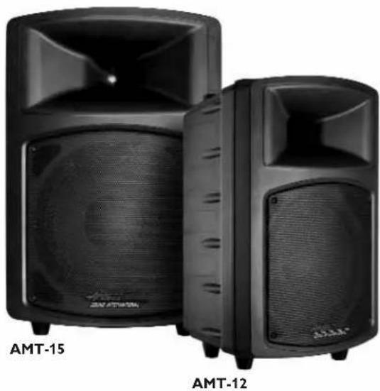
Black audio player with speaker grille and front panel, no visible text or symbols on bodyAMT-12 AMT-15
Professional Loudspeakers
Installation and Use Manual
Table of Contents
Introduction 2
Speaker Mounting 2.
Powering the Loudspeaker 3
Input Panel 3
Daisy-Chaining Speakers 4
Speaker Block Diagram 4.
Connector Wiring Diagram 4
Specifications 5
Limited Warranty 6
Notice
Every effort was made to ensure that the information in this guide was complete and accurate at the time of printing. However, information is subject to change.
Introduction
natural_image
Two black AMT-15 and AMT-12 audio speakers with visible sound waves (no text or symbols on devices)The AMT-12 is designed to deliver high-output music and sound reinforcement in a lightweight package. The 12-inch woofer has high sensitivity to maximize amplifier output. The 1.77-inch compression driver diaphragm, comprised of an titanium-alloy for added strength and rigidity, effortlessly handles the high input levels to match the woofer. A carefully designed cross-over network accurately filters each driver for proper matching of phase and summation in the cross-over region. The transition is much smoother than other loud-speakers in this class, making the sound more accurate and more realistic.
The AMT-15 combines the same high-output compression driver used in the AMT-12 with a robust 15-inch woofer. The sound quality is enhanced further by a richer, dynamic bass response which extends a full 10 Hz lower. The AMT-15 can fill larger rooms with more power than competitive models, and with much more accurate sound.
Speaker Mounting
Single Speaker
The Apogee AMT loudspeakers may be deployed individually by several methods. First, the loudspeakers may be stacked directly on one another using the built-in feet on each speaker.
Both the AMT-12 and AMT-15 may be mounted on stands using the integrated 35mm (1-3/8") stand mount on the bottom of the enclosure. Because of the light weight of the AMT loudspeakers, plus the convenient integral handle, one person can set up multiple speakers on stands easily and quickly.

IMPORTANT: The integrated pole cup is provided for vertical speaker orientation only. DO NOT use this mount for applications requiring off-plumb orientations.
The loudspeakers may also be suspended by attaching forged eye-bolts to the rigging points of the speakers (Rigging point: depth 15mm, diameter M8, thread pitch 1.25mm). There are two rigging points located on the speakers' top and two on the bottom. Plastic screw caps protect the rigging points. The enclosures can be suspended from these points with stainless steel wire rope or an equivalent approved by a qualified engineer and/or your local code enforcement office.

Note: The rigging points are only for suspending the speaker itself. Do not suspend other speakers or equipment from the speaker's rigging points.
Multiple Speakers
The Apogee AMT loudspeakers have a coverage angle of 65 degrees horizontally by 65 degrees vertically. Should this not be sufficient to properly cover the listening area, or if the acoustic output of a single speaker is not great enough, multiple AMT loudspeakers may be arrayed to provide greater coverage or higher on-axis SPL. The preferred method of arraying two loudspeakers is with the Apogee Adjustable Rigging Beam Assembly (Part No. 109-2140). The rigging beams allow for user adjustment of the splay angle between the cabinets from 0 degrees "Tight Pack" to 30 degrees of splay.
In a Tight Pack Array, the total coverage of the array will be slightly greater than that of a single speaker. Because of the overlap in coverage between the speakers in the Tight Pack configuration, the on-axis SPL will increase 3dB. As the splay angle increases, the on-axis SPL will slowly decrease back to that of a single speaker and the coverage angle will widen to a maximum of 120 degrees horizontal.
Powering the Loudspeaker
Amplifier Selection
It is important that the appropriate amplifier be used for a specific loudspeaker to avoid accidental driver damage. Underpowered amplifiers will clip easily, sending a highly distorted signal to the speaker. This distorted signal has a far greater density of energy than normal program and will “burn out” drivers quickly.

Note: Be certain that the total impedance of all interconnected speakers is not lower than the amplifier's minimum rated impedance. The AMT-12 and AMT-15 are 8-ohm speakers.
Wire Selection
Good quality speaker cable of the appropriate gauge is a worthwhile investment. Not all of the power generated by your amplifier is delivered to your loudspeakers. Some power is lost as heat in the speaker cable. While this heat is rarely enough to be a fire hazard, it can reduce a significant amount of amplifier power delivered to the loudspeakers. In addition to loudspeakers not reaching their full potential loudness, undersized wire will also decrease the woofers' ability to respond accurately to transients, leaving the bass response loose and inarticulate.
The appropriate wire size depends on the distance between the amplifier and the speaker and the final combined impedance of the speaker or speakers at the end of the cable run. Here is a list of recommended wire gauges:
| Distance from Amp to AMT Speaker | 8 Ohms(1 Speaker) | 4 Ohms(2 Speakers) |
| 50 Feet | 16 AWG 16 AWG | |
| 100 Feet 14 AWG 12 AWG | ||
| 200 Feet | 12 AWG 10 AWG | |
| 400 Feet | 10 AWG | 8 AWG |
Input Panel
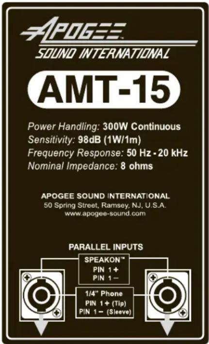
The AMT-12 and AMT-15 use combination Speakon-type plus 1/4" Phone-type connectors. Each AMT speaker has a pair of these connectors wired in parallel, so that a second speaker can be connected to the first speaker if required.
AMT-12 Panel

AMT-15 Panel
Daisy-Chaining Speakers
In these examples, pins 1+ and 1- on the Input (Left) connector receive full-range audio from the amplifier or from a previous speaker in a chain.
The Parallel Input (Right) connector uses the 1+ and 1- pins to send full-range audio to the Input connector of another speaker in a chain.
Loop-Thru connects all speakers in the chain in parallel. Make sure the total impedance of the chain is not less than what the amplifier is rated to handle.
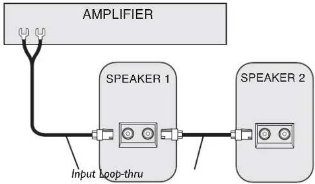
In Example A, the speakers are connected with Speakon™ connectors from the Amplifier to Speaker 1, then from Speaker 1 to Speaker 2.
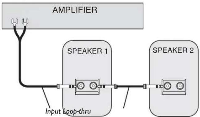
In Example B, the speakers are connected with the 1/4" Phone connectors from the Amplifier to Speaker 1, then from Speaker 1 to Speaker 2.
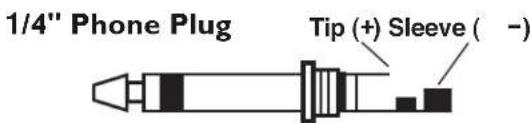
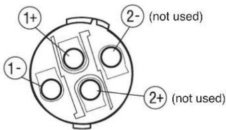
When wiring the Speakon™ connector, use Pins 1+ and 1-. For the 1/4" Phone plug, use Tip (+) and Sleeve (-). DO NOT wire more than two speakers in parallel unless the amplifier is rated for operation at less than 4 ohms.
Example A
flowchart
graph LR
    A["AMPLIFIER"] --> B["SPEAKER 1"]
    B --> C["SPEAKER 2"]
    B --> D["Input Loop-thru"]
    C --> D
Example B
flowchart
graph LR
    A["AMPLIFIER"] --> B["SPEAKER 1"]
    B --> C["SPEAKER 2"]
    B --> D["Input Loop-thru"]
    C --> D
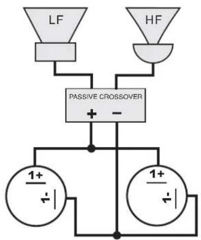
Speaker Block Diagram
1+: Phone Plug Tip and Speakon™ Pin 1+ 1-: Phone Plug Sleeve and Speakon™ Pin 1-
flowchart
graph TD
    A["LF"] --> C["PASSIVE CROSSOVER"]
    B["HF"] --> C
    C --> D["1+/-"]
    C --> E["1+/-"]
Connector Wiring Diagram (View from terminal side)
Wire like-named pins together to make loop-thru speaker cables.
Speakon™ Plug
AMT-Series Loudspeaker Specifications
| SPECIFICATIONS | AMT-12 |
| Frequency Response (-10 dB)° | 60 Hz to 20 kHz |
| LF Driver | 12" High-Sensitivity Design |
| HF Driver | 1.77" Titanium-Alloy Diaphragm Compression Driver |
| Sensitivity (1W/1m) | 96 dBspl |
| Impedance Ratings 8 ohms | Nominal |
| Power Input (Max.) 200W | at 8 ohms continuous |
| Dispersion 65° H × 65° V | |
| Enclosure Material Mineral | filled Polypropylene |
| Grille Material Perforated Steel | |
| Terminations | Combo Input Connectors; 1/4" Phone & SpeakonTM |
| Product Weight 37 lb. | |
| Speaker Dimensions | 23" H × 16.25"W × 13" D |
| Included Accessories Stand | -mount Clamping Screw |
| Optional Accessories | Adjustable Rigging Beam Assembly, AMT Rigging Kit, Tripod Stand |
| Color Black | |
* Free Space Response
| SPECIFICATIONS | AMT-15 |
| Frequency Response (-10 dB)° | 50 Hz to 20 kHz |
| LF Driver | 15" High-Sensitivity Design |
| HF Driver | 1.77" Titanium-Alloy Diaphragm Compression Driver |
| Sensitivity (1W/1m) | 98 dBspl |
| Impedance Ratings 8 ohms | Nominal |
| Power Input (Max.) 300W | at 8 ohms continuous |
| Dispersion 65° H × 65° V | |
| Enclosure Material Mineral-filled Polypropylene | |
| Grille Material Perforated Steel | |
| Terminations | Combo Input Connectors; 1/4" Phone & SpeakonTM |
| Product Weight 47 lb. | |
| Speaker Dimensions | 27" H × 19"W × 15" D |
| Included Accessories Stand | -mount Clamping Screw |
| Optional Accessories | Adjustable Rigging Beam Assembly, AMT Rigging Kit, Tripod Stand |
| Color Black | |
* Free Space Response
Limited Warranty; Exclusion of Certain Damages
Apogee Sound AMT-12 and AMT-15 Loudspeakers are warranted to be free from defects in material or workmanship for three (3) years from the date of sale to the original purchaser. Any part of the product covered by this warranty that, with normal installation and use, becomes defective will be repaired or replaced by Apogee, at our option, provided the product is shipped insured and prepaid to: Apogee Sound Factory Service Department, 50 Spring Street, Ramsey, NJ 07446, USA. The product will be returned to you freight prepaid. This warranty does not extend to any of our products that have been subjected to abuse, misuse, improper storage, neglect, accident, improper installation or have been modified or repaired or altered in any manner whatsoever, or where the serial number or date code has been removed or defaced.
THE FOREGOING LIMITED WARRANTY IS APOGEE'S SOLE AND EXCLUSIVE WARRANTY AND THE PURCHASER'S SOLE AND EXCLUSIVE REMEDY. APOGEE SOUND MAKES NO OTHER WARRANTIES OF ANY KIND, EITHER EXPRESS OR IMPLIED, AND ALL IMPLIED WARRANTIES OF MERCHANTABILITY OR FITNESS FOR A PARTICULAR PURPOSE ARE HEREBY DISCLAIMED AND EXCLUDED TO THE MAXIMUM EXTENT ALLOWABLE BY LAW. Apogee's liability arising out of the manufacture, sale or supplying of products or their use or disposition, whether based upon warranty, contract, tort or otherwise, shall be limited to the price of the product. IN NO EVENT SHALL APOGEE BE LIABLE FOR SPECIAL, INCIDENTAL OR CONSEQUENTIAL DAMAGES (INCLUDING, BUT NOT LIMITED TO, LOSS OF PROFITS, LOSS OF DATA OR LOSS OF USE DAMAGES) ARISING OUT OF THE MANUFACTURE, SALE OR SUPPLYING OF PRODUCTS, EVEN IF APOGEE HAS BEEN ADVISED OF THE POSSIBILITY OF SUCH DAMAGES OR LOSSES. Some States do not allow the exclusion or limitation of incidental or consequential damages, so the above limitation or exclusion may not apply to you. This warranty gives you specific legal rights, and you may also have other rights which vary from State to State.
Products that are out of warranty will also be repaired by the Apogee Sound Factory Service Department – same address as above or call 201-934-8500. The parts and labor involved in these repairs are warranted for 90 days when repaired by the Apogee Sound Factory Service Department. All shipping charges in addition to parts and labor charges will be at the owner's expense. All returns require a Return Authorization number.
7/22/2008
- AMT-12 AMT-15
- Professional Loudspeakers
- Table of Contents
- Notice
- Introduction
- Speaker Mounting
- Single Speaker
- Multiple Speakers
- Powering the Loudspeaker
- Amplifier Selection
- Wire Selection
- Input Panel
- Daisy-Chaining Speakers
- Speaker Block Diagram
- Connector Wiring Diagram (View from terminal side)
- AMT-Series Loudspeaker Specifications
- Limited Warranty; Exclusion of Certain Damages
Brand : Bogen
Model : AMT-12
Category : Loudspeaker